Max-Prop Easy & Whisper Installation Instructions - PYI Inc.
Max-Prop Easy & Whisper Installation Instructions - PYI Inc.
Max-Prop Easy & Whisper Installation Instructions - PYI Inc.
- No tags were found...

Create successful ePaper yourself
Turn your PDF publications into a flip-book with our unique Google optimized e-Paper software.
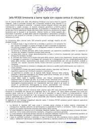
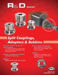
BYInstruction ManualEASY / WHISPER3, 4 & 5 BladesScan the QR codewith a mobiledevice to view theinstallation video.
1)INTRODUCTION:Thank you for having chosen a MAX PROP ® automatic feathering propeller for your vessel. Thisinstruction booklet is designed to answer all your questions on installation and use of the <strong>Max</strong>-<strong>Prop</strong>.Please read it carefully and verify the correct working of the propeller before installing it on your boat.2)INSTALLATION:The propeller is supplied already assembled for right or left rotation, according to the informationreceived at order and with the pitch required if discussed at the time of the order, and is thereforeready to be fitted on the shaft. MAX PROP ® parts are NOT interchangeable. Make sure, if youreceive more than one propeller, that you do not interchange parts.x1x2x3x1x1x1x1For Sail Drivesx2
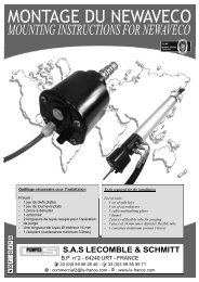
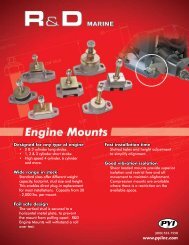
GREASEGREASEGREASEA)Fit the MAX PROP ® onto the propeller shaft, like a fixed propeller, and be sure that the keyis proper dimension: A properly fit key has almost no clearance side to side but a very smallclearance on its upper surface. This clearance is to avoid the propeller being pushed off center bya key which is too tall.Fig.1B)Tighten the nut and secure it in place using the two allen head screws. For a Sail Drive only nexttighten the center bolt and secure it with the set screw through the side.C)D)Fit the zinc and secure it with the three allen bolts. Make sure that the zinc and the propeller areclean to insure good contact.Fill the prop with marine grease (supplied) using a grease fitting (supplied) inserted into the greaseholes on the side of the propeller marked “GREASE”. The MAX PROP ® EASY propeller worksproperly only if the central body is completely filled with the correct grease. Verify that the greaseis oozing from the rotating joints between the central part and the hub, so that all of the movingsurfaces are perfectly greased. The grease used must be a type of grease approved by MAX PROP ®so it will remain fluid after years of use and will not get too stiff in cold water.123GREASEGREASEGREASE
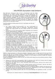
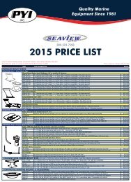
3)PITCH ADJUSTMENT:The pitch on a MAX PROP ® changes according to the diameter and the blades rotation angle. Fig. 3shows the pitch in inches corresponding to the degree of blades angle for a given propeller diameter.Blade Angle<strong>Prop</strong>eller Diameter12” 13” 14” 15” 16” 17” 18” 19” 20” 21” 22” 23” 24” 25” 26”10º 4 4.3 4.6 4.9 5.2 5.5 6 6.3 6.7 7.1 7.4 7.7 8 8.3 8.612º 4.8 5.2 5.6 6 6.4 6.8 7.2 7.6 8 8.4 8.8 9.2 9.6 10 10.414º 5.6 6 6.6 7.1 7.6 8 8.4 8.8 9.4 9.8 10.4 10.8 11.2 11.6 12.216º 6.4 6.9 7.6 8.1 8.6 9.1 9.8 10.3 10.8 11.3 12 12.5 13 13.5 1418º 7.2 7.8 8.6 9.2 9.8 10.4 11 11.5 12.1 12.8 13.4 14 14.6 15.2 1620º 8.2 8.9 9.6 10.3 11 11.6 12.4 13 13.7 14.5 15 15.6 16.4 17 17.822º 9.2 10 10.7 11.4 12.2 12.9 13.6 14.3 15.1 16 16.8 17.5 18.2 18.9 19.824º 10 10.9 11.8 12.5 13.4 14.2 15 15.8 16.8 17.6 18.4 19.2 20.2 21 21.826º 11 12 12.8 13.8 14.7 15.7 16.6 17.4 18.4 19.3 20.2 21 22 22.9 23.828º 12 13 13.9 15 16 17 18 18.9 20 21 22 23 24 25 2630º 13 14 15.1 16.2 17.3 18.5 19.6 20.6 21.7 22.8 24 25 26.1 27.3 28.2Fig.3<strong>Inc</strong>hes of PitchDiameter and pitch must be calculated as if MAX PROP ® EASY was a normal fixed propeller. MAXPROP ® EASY then offers the great advantage of pitch adjustability in order to optimize the performanceof the propeller. If the engine does not reach the desired RPM, reduce the blade angle; on the contrary,if the engine exceeds the desired RPM, increase the blade angle.Fig.3b
PITCH ADJUSTMENT ContinuedThe MAX PROP ® EASY allows an angle variation of 2 degree increments, this corresponds to avariation in the engine RPM of about 13% at the same boat speed. It’s possible to change either the pitchto optimize the engine performance, or the rotation (for ex. if you change the engine, or if there werea mistake when ordering the prop). If you have doubts about the rotation: shaft rotation is determinedfrom the stern of the boat looking forward. With the engine in forward position clockwise rotation ofthe propeller means it is right hand “R”, and a counterclockwise rotation is a left hand “L”.Pitch and rotation of the MAX PROP ® EASY can be changed as follows:On the body of the propeller are two threaded bores, marked with letters “R” and “L”; within thesebores are placed two bolts.The pitch of the propeller, both in front and reverse position, can be easily varied by changing thesupplied bolts threaded into the body of the propeller with other bolts of a different length.The pitch in forward rotation varies changing the bolts placed in bore “R” if the propeller is righthandedor changing the bolts placed in bore “L” if the propeller is left-handed. The list of the pitchregulation bolts, that are supplied with every EASY propeller is indicated in fig. 4For example inserting the #20 bolt in the forward rotation and 2 in the reverse rotation will provide a 20degree angle for both front position and reverse rotation. Varying 1 millimeter the length of the bolts,blades inclination has a 2 degrees variationFig.4Blade AngleDegreesRight RotationLeft RotationForward Bore “R” Reverse Bore “L” Forward Bore “L” Reverse Bore “R”16 16 1 16 118 18 1820 20 2 20 222 22 2224 24 3 24 3Close up of the Left andRight pitch adjustment bolts.Fig.5
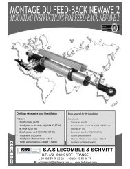
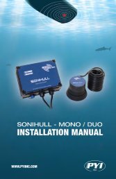
CHANGING THE ROTATIONZINC SCREWSZINCNUTHUBNUT SCREWSRINGMARKRLFig.6With the MAX PROP EASY® it is also possible to change the rotation, e.g. if you change the engine, orif there was a mistake when ordering the prop. If you have doubts about the engine rotation, it can bedetermined looking forward from the stern of the boat. With the engine in forward position a clockwiserotation of the propeller means it is right handed(R), and a counter-clockwise rotation is left handed (L).In order to change the rotation of the MAX PROP EASY®, from a right hand rotation to a left handrotation or vice versa do as follows, referring to fig.61. Place the propeller in the feathered position. Unscrew the locking-zinc screws, and remove the zinc2. Unscrew the locking-nut screws and remove the nut3. Remove the Circlip on the aft edge of the hub4. Be sure the propeller is in the feathered position, then release the zinc-bearing ring5. Once released the zinc-bearing ring, you see that on one tooth of the hub (the aft side)there is areference mark, and a tooth of the bearing-zinc ring are marked one with “L” and the other with“R”.6. If you place the zinc bearing ring in its seat again, matching the “L” tooth with the hub referencemark, you have a left hand rotating propeller, on the contrary, with the “R” tooth you have a rightrotating propeller as in fig.47. Replace the “Circlip” in to its seat8. Tighten the nut and secure it with the locking-nut screws9. Place the zinc again, and secure it with the 3 proper screws10. Be sure to change the pitch setting bolts to reflect the pitch setting for the new rotation.
4)PROPELLER USE:The MAX PROP ® EASY works automatically. By putting the transmission in gear the blades willengage in either forward or reverse (WARNING: do not change from forward to reverse and viceversa when the engine is running at high RPM ) and feathers from forward position when youturn off the engine and lock the shaft.The best way to feather the propeller is:• Power at 2 to 3 knots in forward.• Kill the engine while still engaged in forward.5)If your propeller has been greased properly it will feather in a fraction of a second as soon asyou stop the shaft from freewheeling. DO NOT kill the engine while in reverse. In this case theblades will be in the reverse position and cannot feather. You can actually use this feature to drivea shaft alternator.Modern transmissions are either mechanical or hydraulic. With a mechanical transmission, thebest way to stop the shaft freewheeling is to engage the transmission in reverse ( WARNING:engage the reverse only after the engine has stopped completely). With a hydraulic transmissionyou must shut off the engine while still engaged in forward. The remaining hydraulic pressure willen effect lock the shaft for a few moments, enough for the MAX PROP ® to feather.MAINTENANCE:• The propeller must always be completely filled with recommended grease, the propellershould be greased at least once a year.• Make sure that you always keep the zinc anodes in good condition. They must be replaced atleast once a year, even if they still look ok. The propeller must be protected by a lot of zinc,so also use a zinc on the shaft when possible. When replacing it make sure that you clean thesurfaces between the zinc and the propeller shaft in order to have a good electrical contact.WARNING:It is important to follow the instruction below carefully so as to avoid a shock load to thegears on the blades and cone gear, that could be damaging to the teeth.• When going from forward to reverse and the opposite, it is necessary to idle down andshift at low RPM’s between gear, that could be damaging to the teeth.6)PROPELLER REMOVAL:In order to remove the propeller you must firstremove the zinc and remove the nut. Next fit a longarmed gear puller over the front of the propelleras show in fig. 7. Tightening the center bolt of thegear puller will release the MAX PROP ® from thepropeller shaft.Fig.7If the bolt from the gear puller is not long enoughto contact the end of the propeller shaft insidethe MAX PROP ® the MAX PROP ® nut can beloosened and left in place. In this scenario the boltfrom the puller will push against the back of the nutto release the propeller from the shaft.
7)INSTRUCTIONS FOR THE PROPER FITTING OF THELOCKING NUT OF THE PROPELLER FIG.81. When it’s locked on the motor shaft, the nut must contact the 3 surfaces S1, S2, S3. Therefore,if a new nut has to be machined you must be sure that length L1 and L2 coincide preciselywith the corresponding lengths of prop hub, and that length L3 is greater than the length ofthe threaded edge of motor shaft. To check that the work is done properly, you just have tospread a very thin coat of Prussian blue on the 3 surfaces S1, S2, S3. Insert then the nut in itsseat in the hub and let the nut rotate softly in relation to the hub, with a light pressure. Whenthis is done, the 3 surfaces of the hub must be painted in blue.2. When fitting the prop on the motor shaft, it’s necessary to check that the threaded part of themotor shaft doesn’t touch the threaded end of the nut. Also, when the nut is tight, the bladesrotation on their axis does not get hard. In case the blades rotation movement becomes hard,you have to remove from surface S1 a very small amount of material. This operation can bedone simply by using a flat smooth file.Fig.88)SPECIAL NUT (FIG.9) ONLY FOR MAX PROP WITHANTI-SHOCK DEVICE FOR SAIL DRIVEUnlike the standard nut, this kind of nut, when it’s locked on the motor shaft, must lean ONLYto surfaces S1 and S2 and is secured by 4 devices: 2 threaded pins, and a central screw with adowel. When you mount the propeller on the motor shaft the same nut checking is necessary aspreviously described for fig. 8.Fig.9
NOTES
MAX PROP PATENTED PROPELLERS<strong>PYI</strong> <strong>Inc</strong>., 12532 Beverly Park Rd., Lynnwood, WA 98087Tel: 425-355-3669 Fax: 425-355-3661 info@pyiinc.com www.max-prop.com