Wartsila Brochure - Clean Shipping Technology
Wartsila Brochure - Clean Shipping Technology
Wartsila Brochure - Clean Shipping Technology
- No tags were found...
You also want an ePaper? Increase the reach of your titles
YUMPU automatically turns print PDFs into web optimized ePapers that Google loves.
<strong>Technology</strong> review
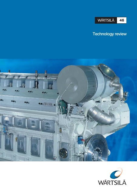
<strong>Technology</strong> reviewThis is a brief guide to the technical features andperformance of the Wärtsilä 46 engines.Design philosophy . . . . . . . . . . . . . . . . 4Development policy . . . . . . . . . . . . . . . 4Exhaust emissions . . . . . . . . . . . . . . . . 5Combustion Air Saturation System (CASS) . . . 6Direct Water Injection (DWI) . . . . . . . . . . . 7Fuel system. . . . . . . . . . . . . . . . . . . . 8Fuels . . . . . . . . . . . . . . . . . . . . . . 10Turbocharging system . . . . . . . . . . . . . 10Piston . . . . . . . . . . . . . . . . . . . . . . 11Cylinder liner and anti-polishing ring . . . . . . 12Piston ring set. . . . . . . . . . . . . . . . . . 12Connecting rod . . . . . . . . . . . . . . . . . 13Crankshaft . . . . . . . . . . . . . . . . . . . 13Cylinder head . . . . . . . . . . . . . . . . . . 14Bearings. . . . . . . . . . . . . . . . . . . . . 14Camshaft and valve gear . . . . . . . . . . . . 15Engine block . . . . . . . . . . . . . . . . . . 15Cooling systems . . . . . . . . . . . . . . . . 17Lubricating oil system. . . . . . . . . . . . . . 17Automation system . . . . . . . . . . . . . . . 18Maintenance . . . . . . . . . . . . . . . . . . 19Main technical data . . . . . . . . . . . . . . . 193
Design philosophyWärtsilä engine designs are based on generations ofknow-how combined with innovations in response tocustomer needs.The WÄRTSILÄ ® 46 engine offers customers thefollowing core values: Real reliability Low operating costs Low exhaust gas emissions Easy and cost-effective installation Proven flexible mounting technology Easy maintenanceThe Rio Negro Power Master plant in Manaus, Brazil. The plant hasa total capacity of 158 MW and is equipped with ten 18-cylinderWärtsilä 46 engines as prime movers.Wärtsilä works in close co-operation with the customerin conducting field tests and follow-ups of selected testcomponents. Data on wear rates, maintenance intervalsand consumption rates are collected regularly. Thisactivity is part of a long-term customer relationshipcreating an even better product.Development policyThe Wärtsilä 46 is a medium-speed engine for whichReliability and Total Economy have been the guidingprinciples.Extensive testing in our modern diesel laboratorybacked up by several thousand running hours have madethe Wärtsilä 46 a Really Reliable diesel engine. Laboratorytesting is full-scale engine testing: it covers various types ofendurance testing, and also combustion measurementsand system optimizations. All these confirm theoreticalcalculations, simulations as well as performance mappingof such factors as heat balance, fuel and lube oilconsumption, exhaust emission, noise and vibration level.Due to its excellent combustion performance and reliability levelthe Wärtsilä 46 has become the most popular engine for powergeneration onboard new cruise vessels. Voyager of the Seas isequipped with six 12-cylinder Wärtsilä 46 V-engines with a totaloutput of 75,600 kW.4
Exhaust emissionsThe emphasis on environmental issues has steadily grownand it is expected to grow further in the future. The mainfocus has been on nitrogen oxides (NO X ) emissions,sulphur oxides (SO X ) and particulate emissions. Latelymuch attention has been paid to CO 2 due to the KyotoProtocol and in the marine sector smokeless operation hasbecome important especially for cruise ships. CO 2 and SO X emissions are practically directlyproportional to the carbon and sulphur content of thefuel and the fuel consumption. The superior fuelefficiency of diesel engines therefore gives lower CO 2and SO X emissions than most other power sources,when comparing operation on the same fuel. Generally diesel engines have very low CO and THC(Total HydroCarbon) emissions compared to otherpower sources thanks to the efficient combustion. Smoke is by definition visible. In the exhaust from adiesel engine smoke consists of soot particles that arelarge and concentrated enough to become visible.Smokeless operation at any load is achieved withcommon rail fuel injection, which maintains anoptimum fuel injection pressure also at low load andreduced speed. The ash content of the fuel stronglyaffects both smoke and particulates. The factor that has the most significant influenceon NO X formation is the temperature. Therefore themost successful approach to lower NO X emissions is toreduce the peak temperatures during the combustion.The available means to achieve stable and lowcombustion temperatures can be divided into drymethods and wet methods. Dry methods involve of optimum shape of thecombustion chamber, high compression ratio,sophisticated fuel injection equipment and adapted camprofile, optimised turbocharging system for correct airto fuel ratio and internal cooling of the cylinder byearlier closing of the air intake valves (Miller concept). The principle of wet methods is to introduce water intothe combustion chamber. Wärtsilä has developed a newtechnology for addition of water named CASS(Combustion Air Saturation System), which brieflydescribed means that pressurized water is injectedLow NOXcombustionCylinder pressureCylinder pressureSpecific NO emissions (g/kWh)XConventional designTDCEngine maximum firing pressurePressure riseinduced fromcombustionPressure riseinduced fromcompression-90 -60 -30 0 30 60 90 120Low NOXdesignTDCEngine maximum firing pressurePressure riseinduced fromcombustionPressure riseinduced fromcompression-90 -60 -30 0 30 60 90 120NOXemissions compliance of Wärtsilä enginesReference fuel MDO18CASS = Combustion Air Saturation System16SCR = Selective Catalytic Reduction14Standard12 Wärtsilä 4610Low NOXcombustion86Direct Water Injection or CASS4SCR2Low-speed0Medium-speedHigh-speed0 200 400 600 800 1000 1200 1400 1600 1800rpmWorld Bank“Thermal Power – Guidelines for New Plants” 1998NO mg/nm (dry, 15 vol-% O , 0 °C)23X2200200018001600140012001000800600400200Non-degraded airshed:2000 mg/nm 3 (dry, 15 vol-% O , 0 °C)Compliance withprimary methodsDegraded airshed:400 mg/nm 3 (dry, 15 vol-% O , 0 °C)22Compliance usingSCR techniquesand proper fuelchoice5
directly after the compressor of the turbocharger. Lesswater is required if it is injected directly into thecylinder. The Wärtsilä 46 is available also with DirectWater Injection (DWI) (only for marine applications).Direct water injection is an option for low sulphur fuel.CASS and DWI can be applied in addition to the drymethods already utilised to achieve further NO Xreduction. Selective catalytic reduction (SCR), which is externalfrom the engine, offers the highest possible NO Xreduction.The standard engine meets the NO X level set by IMO(International Maritime Organisation) in Annex VI toMARPOL 73/78, and the World Bank Group specified in"Thermal Power: Guidelines for New Plants, 1998" forengine driven power plants in "non-degraded air sheds".All marine engines are delivered with an EIAPP (EngineInternational Air Pollution Prevention) certificate, technicalfile and marked engine components as required by theNO X Technical Code in MARPOL 73/78 Annex VI.Greenhouse effect and global warmingCFC24%Greenhouse gasesNO 26%CO255%Typical CO2emissions (g/kWhe)for different prime moversCO2 emissions (g/kWhe)9008007006005004003002001000Coal firedsteam boilerGas turbinefuel oilsingle cycleGas turbinenatural gassingle cycleDiesel enginefuel oilsingle cycleGas enginenatural gassingle cycleCombustion Air SaturationSystem (CASS)The new NO X reduction technology developed byWärtsilä is named CASS, for Combustion Air SaturationSystem. The principle of CASS is to introduce water withthe intake air to reduce the combustion temperature andthereby the formation of NO X . Pressurized water isinjected directly after the compressor of the turbocharger.The high temperature of the compressed air evaporates thewater, which enters the cylinders as steam. A water mistcatcher prevents water in liquid state from entering thecylinders. The maximum NO X reduction is typically30-50 % depending on application specific limitations,and the water consumption is normally up to two timesthe fuel oil consumption.Methane15%CompressorAtmospheric concentrations of carbon dioxide since 1750350330310Ice core measurement(Siple station, West Antarctia)Direct measurements(Mauna Loa, Hawaii)WaterinjectionSaturated air70...90°C29027017001750 1800 18501900 1950 2000Source: Environmental Data Report, UNEP 19906
The 267,4 MW Pavana III oil power plant in Honduras is powered by sixteen Wärtsilä 18V46 generating sets.Direct Water Injection (DWI)Direct Water Injection reduces NO X emissions typicallyby 50-60 % without adversely affecting the power output.Built-in safety features enable immediate water shut-off inthe event of excessive water flow or water leakage. Thewater system is completely separate from the fuel system:if water shut-off should prove necessary, engine operationis not affected. The water-to-fuel ratio is typically withinthe range 0.4-0.7. Direct water injections is an option forlow sulphur fuel (below 1.5%).AccumulatorFlow fuseDWI valveWater toDWI valveWater inlet7
M/S Mistral delivered to Godby <strong>Shipping</strong> in January 1999 – one ofthe first of seven forest product carriers equipped with DirectWater Injection, (12V46, output 12 600 kW) .The Silja Symphony and its sister vessel Silja Serenade areequipped with Direct Water Injection on all main engines(4 x 9L46).Fuel systemThe Wärtsilä 46 is available with conventional fuelinjection, or optionally with common rail fuel injectionfor smokeless operation also at low load.The entire fuel system is enclosed in a fully coveredcompartment for maximum safety. All leakages frominjection valves, pumps and pipes are collected in closedsystem.Conventional fuel injection The monoelement injection pump design is a rigid adistortion-free solution for high injection pressures. A constant pressure relief valve in the injection pumpeliminates the risk of cavitation erosion by maintaininga residual pressure, which is on a safe level over thewhole operating field. A drained and sealed-offcompartment between thepump and the tappet preventsleakage fuel from mixing withlubricating oil. Precalibrated pumps areinterchangeable. The injection valve is designedto have a small heat absorbingsurface facing the combustionspace. Together with efficientheat transfer to the coolingwater this eliminates the needfor a separate nozzletemperature control system.8
Shielded high-pressure pipesInjection valveHigh pressurepumpAccumulatorDrive camAccumulatorCommon rail fuel injectionThe common rail system comprises pressurizing fuelpumps, fuel accumulators and electronically controlledfuel injectors. The fuel pumps are driven by the camshaftand each pump and accumulator serve two cylinders.Adjacent accumulators are connected with small borepiping in order to reduce the risk of pulsation in the rail.The engine can operate with one or two fuel pumpsdisconnected, should this ever be necessary. A safetyfeature of the system is that there is no pressure on theinjection nozzles between injections. All functions arecontrolled by the embedded control system on the engine.The main advantage of the common rail system is thatthe injection pressure can be kept at a sufficiently highlevel over the while load range, which gives smokelessoperation also at low load.”Enviroengine” is a wider concept than common rail and smoke isby definition visible. Only MAN speak about “invisible smoke”.Wärtsilä CR engines are smokeless.9
FuelsThe Wärtsilä 46 engine is designed and developed forcontinuous operation on fuels with the followingproperties:Diesel oil & HFODiesel oils (distillate oils) have traditionally been the fuelsfor diesel engines. Heavy fuel oils (HFO) have been usedin Wärtsilä engines since the 1970’s. During the recentyears, oil refineries have developed processes to increasethe yield of high-revenue products resulting in poorerquality residues. This means higher sulphur content,higher ash content and worse combustion properties.High viscosity HFOsAmong the recently approved fuels, there are varieties ofhigh-viscosity mineral oils that can be found eithernaturally in e.g. oil-sand or as heavy residues from oilrefineries.Crude oilsCrude oils are especially suitable for pumping stationsalong crude oil pipelines and for electricity production atoil fields. Crude oils have been in frequent use as fuels forWärtsilä engines at power plants and oil pumping stationssince mid 1990-ties.Emulsified fuelsEmulsification offers means of utilising fuels with evenhigher viscosity. Among the emulsified fuels, theVenezuelan Orimulsion ® is already in commercial use andother qualities are being evaluated. The high watercontents in these fuels facilitate the handling of these fuelsalmost in the same way as conventional fuel oils and theyhave advantageous effects on the exhaust gas emissions.These fuels will be of importance in the future.Liquid bio fuelVegetable based bio oils have been accepted for Wärtsiläengines since 1996 and they have found commercial usefor diesel power plants. Olive oil, palm oil, soy bean oiland rape seed oil are some of the main qualities among thebio oils, all usable as diesel fuel. Biodiesel, transesterifiedbio oil, can also be used.Turbocharging systemWärtsilä 46 is provided with Spex (Single pipe exhaust)system and with high efficiency turbocharger. The Spex turbocharging system is an exhaust gas systemthat combines the advantages of both pulse andconstant pressure charging. Compared with a constant pressure system, the ejectoreffect of the gas pulses will provide better turbineefficiency at partial loads. The Spex system is practically free from interference.This means very small deviations in the scavengingbetween the cylinders and consequently an even exhaustgas temperature. The modular-built exhaust gas systems are durableenough to handle high pressure ratios and pulse levels,but at the same time elastic enough to cope withthermal expansion in the system. The turbocharger has the highest available efficiency. The turbocharger is equipped with plain bearings andthere is no cooling water. The turbocharger is fitted with cleaning devices for boththe compressor and the turbine side. Exhaust waste-gate and air by-pass are used to obtainspecific requirements on the operating range, loadresponse or partial load.10
Piston A composite low-friction piston with a nodular cast ironskirt and a steel top. The special cooling gallery design assures efficientcooling and high rigidity for the piston top. The designcan handle combustion pressures beyond 200 bar. Hardened top ring grooves assure a long lifetime.Low friction is ensured by the skirt lubrication systemfeaturing: A well distributed clean oil film that eliminates the riskof piston ring scuffing and reduces the wear rate. <strong>Clean</strong>er rings and grooves free from corrosiveombustion products. Hydraulically damped tilting movements provided byan oil pad between the liner and the piston, resulting inless noise and wear.11
Piston ring set Low friction three-ring set Special wear resistantcoating for the compressionrings Dimensioned and profiledfor maximum sealing andpressure balanceCylinder liner andanti-polishing ringCylinder liner deformations are normally caused bycylinder head clamping, thermal and mechanical load.Thanks to a special design with a high collar-to-strokeratio, the deformations in this liner are very small. Around liner bore in combination with excellent lubricationimproves conditions for the piston rings and reduces wear.To eliminate the risk of bore polishing, the liner isprovided with an anti-polishing ring in the upper part.The purpose of this ring is to “calibrate” the carbondeposits on the piston top land to a thickness smallenough to prevent contact between the liner inner wall andthe deposits on the piston top land. “Bore-polishing” canlead to local liner wear and increased lube oilconsumption.The temperature distribution in the cylinder liner isimportant not only in terms of stress and deformation butalso decisive for the cylinder liner wear rate. Thetemperature must remain above the sulphuric acid dewpoint to avoid corrosion, but at the same time remainsufficiently low to avoid lubricating oil breakdown.The material composition is based on long experience withthe special grey cast iron alloy developed for excellent wearresistance and high strength.12
Connecting rodThe connecting rod is a three-piece marine design, wherecombustion forces are distributed over a maximumbearing area and where the relative movements betweenmating surfaces are minimized. Piston overhauling is possible without touching the bigend bearing and the bearing can be inspected withoutremoving the piston. The three-piece design also reduces the pistonoverhauling height. All nuts are tightened with hydraulic tool.CrankshaftThe crankshaft design allows for use of high combustionpressure and still maintains a conservative bearing load.The crankshaft is: Forged in one piece and fully machined. Rigid due to moderate bore/stroke ratio and large pinand journal diameters. Fitted with counterweights on every crankweb. Designed for full power take-off, also from the free end .13
Cylinder headThe cylinder head design is based on reliability and easymaintenance. A rigid box like design for even circumferential contactpressure between the cylinder head and the cylinderliner. Four cylinder head fixing bolts are used, whichsimplifies maintenance. No valve cages are used; thisimproves reliability and providesgreater scope for optimization ofthe exhaust port flowcharacteristics. Efficient water-cooled exhaustvalve seat rings. Valve rotators on both exhaustas well as inlet valves guaranteean even thermal and mechanicalload on the valves.BearingsThe Thick-Pad bearing design emphasizes one keyconcept: Reliability.The bearing loads have been reduced by increasingcrankshaft journal and pin diameters as well as length. Low bearing loads allow for softer bearing materialswith greater comformability and adaptability. Thismakes the bearing virtually seizure-free.14
Camshaft and valve gear The camshaft is built of single cylinder sections withintegrated cams. The camshaft sections are connected through separatebearing journals, which makes it possible to remove theshaft sections sideways from the camshaft compartment. The valve follower is of the roller tappet type, where theroller profile is slightly convex for good loaddistribution. The valve mechanism includes rocker arms working onyokes guided by pins. Both exhaust and inlet valves receive a forced rotationfrom Rotocaps during every opening cycle. This forcedrotation provides for even temperature distribution andwear of the valves, and keeps the sealing surface freefrom deposits. Good heat conduction is the result.Engine block The engine block is manufactured of nodular cast ironin order to achieve the rigid and durable constructionneeded for resilient mounting. The main bearings are of the underslung type, withhydraulically tightened bolts. Side bolts add further rigidity to the main bearinghousing. In-line engines are equipped with an integrated airreceiver featuring increased rigidity, simplicity andcleaness.15
Cooling systems The fresh water cooling system is devided into hightemperature and low temperature cooling system. The high temperature cooling water system operatesconstantly at a high temperature level to make thetemperature fluctuations in the cylinder components assmall as possible and preventing from corrosion due toundercooling. For obtaining maximum heat recovery the charge aircooler is split into a high and low temperature section. Engine driven pumps can be provided as an option formarine application. In power plant application, theseare standard.Lubricating oil system Marine engines have dry sump and power plant engineswet sump. The lube oil is treated outside the engine bycontinuous separating. On the way to the engine, the oil passes through a lubeoil cooler, a full flow automatic filter unit and a safetyfilter for final protection. For the purpose of running-in, provision has been madefor mounting special running-in filters in the crankcasein front of each main bearing. Engine driven lube oil pump can be provided as anoption for marine application. In power plantapplication this is standard.17
Automation system Automatic control and safety systems have beendeveloped for unmanned operation and bridge control. The engine speed is controlled by an electronic speedcontrol unit and a hydraulic actuator, or alternatively bya mechanical-hydraulic governor. Overspeed protection is doubled by use of anelectropneumatic system acting directly on each fuelinjection pump and a mechanical device acting on thecontrol shaft. Slow turning prior to starting. Pre-start safety control and startblocking if control functions are not performed. Condition monitoring of main components based onreliabletemperature measurement. Easy plug-in connections of sensors to prefabricatedcabling modules. A more advanced electronic control unit (WECS) withprovision for direct bus-connection will be offered asoption.18
Main technical dataMarine and Power MarinePlant engines enginesCylinder bore 460 mm 460 mmPiston stroke 580 mm 580 mmCylinder output 975 kW/cyl 1050, 1155kW/cylEngine speed 500, 514 rpm 500, 514 rpmMean effective25.4, 26.1 barpressure 24.3, 23.6 bar 28.0, 28.8 barPiston speed 9.7, 9.9 m/s 9.7, 9.9 m/sFuel specification:Fuel oil730 cSt/50°C7200 sR1/100°FISO 8217, category ISO-F-RMK 55MaintenanceDuring design and development the engine manufactureremphasizes the necessity of easy maintenance by includingtooling and easy access in the basic design and byproviding easy-to-understand instructions.The Wärtsilä 46 maintenance principle is substantiatedby the following: A cylinder head with four fixing studs and simultaneoushydraulic tightening of all four studs. A hydraulic jack for the main bearing overhaul. Uniform one-cylinder camshaft pieces. Slip-on fittings are used wherever possible. Exhaust gas system insulation by using easy-to removepanels on a frame that is mounted flexibly on theengine. The three-piece connecting rod allows inspection of thebig end bearing without removal of the piston, and pistonoverhaul without dismantling the big end bearing.Enginetype6L468L469L4612V4616V4618V46*50/60 HzRated power500, 514 rpm975 kW/cyl500, 514 rpm1050 kW/cyl500, 514 rpm1155 kW/cylPower Plants Marine & Power Marine MarineEng. kW Gen. kW kW kW kW5 8507 8008 77511 70015 60017 5505675756585101135015130170765 8507 8008 77511 70015 60017 5506 3008 4009 45012 60016 80018 900* Available only for power plants and diesel electric propulsion.1 kW = 1.3596 hp (metric)Enginetype6L468L469L4612V4616V4618V46Dimensions (mm) and weights (tonnes)6 9309 24010 39513 86018 48020 790A* A B C D F Weight7 5809 49010 31010 26012 345/12 460 1)–8 29010 00510 83010 21012 480/12 590 1)13 6703 3403 260/3 600 1)3 6003 6603 660/3 990 1)3 990* Turbocharger at flywheel end.1) Depending on output.2) Depending on turbocharger and output.2 8803 1803 2703 810/4 530 2)4 530/5 350 1)5 3503820382038203600360036001 4601 4601 4601 5001 5001 5009512013716921424019
W0404/Bock's Office/YkkösoffsetWärtsilä is The Ship Power Supplier for builders, owners and operatorsof vessels and offshore installations. Our own global service networktakes complete care of customers’ ship machinery at every lifecyclestage.Wärtsilä is a leading provider of power plants, operation and lifetimecare services in decentralized power generation.The Wärtsilä Group includes Imatra Steel, which specializes in specialengineering steels.For more information visit www.wartsila.comWÄRTSILÄ ® is a registered trademark. Copyright © 2005 Wärtsilä Corporation.Wärtsilä Finland OyP.O.Box 252,FI-65101 Vaasa,FinlandTel. +358 10 709 0000Fax Ship Power +358 6 356 7188Fax Power Plants +358 6 356 9133


