Operations Guide Tracer AdaptiView⢠Display for Gear ... - Trane
Operations Guide Tracer AdaptiView⢠Display for Gear ... - Trane
Operations Guide Tracer AdaptiView⢠Display for Gear ... - Trane
- No tags were found...

You also want an ePaper? Increase the reach of your titles
YUMPU automatically turns print PDFs into web optimized ePapers that Google loves.
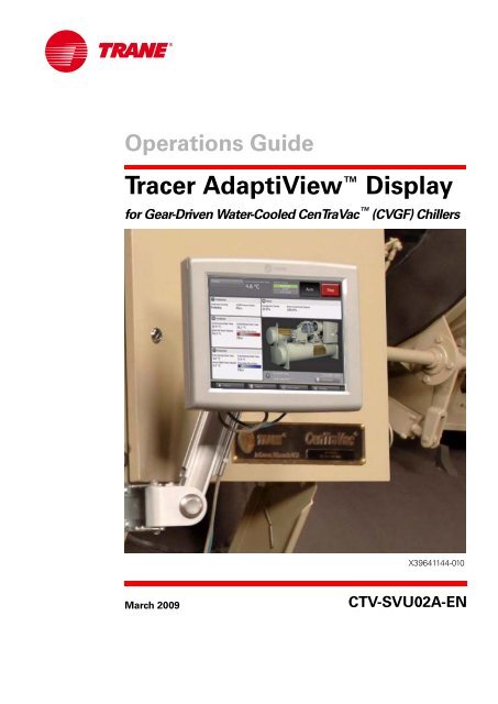
<strong>Operations</strong> <strong>Guide</strong><strong>Tracer</strong> AdaptiView <strong>Display</strong><strong>for</strong> <strong>Gear</strong>-Driven Water-Cooled CenTraVac (CVGF) ChillersX39641144-010March 2009CTV-SVU02A-EN
Copyright© 2009 <strong>Trane</strong> All rights reservedThis document and the in<strong>for</strong>mation in it are the property of <strong>Trane</strong> and may not be usedor reproduced in whole or in part, without the written permission of <strong>Trane</strong>. <strong>Trane</strong> reservesthe right to revise this publication at any time and to make changes to its content withoutobligation to notify any person of such revision or change.TrademarksAdaptiView, CenTraVac, EarthWise, <strong>Trane</strong>, the <strong>Trane</strong> logo, and <strong>Tracer</strong> are trademarks of<strong>Trane</strong> in the United States and other countries. All trademarks referenced in thisdocument are the trademarks of their respective owners.
ContentsIntroduction . . . . . . . . . . . . . . . . . . . . . . . . . . . . . . . . . . . . . . . . . . . . . . . . . . . . . . 5Equipment Description . . . . . . . . . . . . . . . . . . . . . . . . . . . . . . . . . . . . . . . . . . . 5Touchscreen <strong>Guide</strong>lines . . . . . . . . . . . . . . . . . . . . . . . . . . . . . . . . . . . . . . . . . . 6Reference Sources . . . . . . . . . . . . . . . . . . . . . . . . . . . . . . . . . . . . . . . . . . . . . . 6Main Menu Area . . . . . . . . . . . . . . . . . . . . . . . . . . . . . . . . . . . . . . . . . . . . . 13Stopping/Restarting Chiller Operation . . . . . . . . . . . . . . . . . . . . . . . . . . . . . . . . 14Stopping the Chiller . . . . . . . . . . . . . . . . . . . . . . . . . . . . . . . . . . . . . . . . . . . . 14Restarting the Chiller . . . . . . . . . . . . . . . . . . . . . . . . . . . . . . . . . . . . . . . . . . . 15Alarms . . . . . . . . . . . . . . . . . . . . . . . . . . . . . . . . . . . . . . . . . . . . . . . . . . . . . . . . . . 16Viewing the Alarms Screen . . . . . . . . . . . . . . . . . . . . . . . . . . . . . . . . . . . . . . 16Understanding Alarm Icons . . . . . . . . . . . . . . . . . . . . . . . . . . . . . . . . . . . . 17Viewing Active and Historic Alarms . . . . . . . . . . . . . . . . . . . . . . . . . . . . . 17Sorting Alarms . . . . . . . . . . . . . . . . . . . . . . . . . . . . . . . . . . . . . . . . . . . . . . 17Resetting Alarms . . . . . . . . . . . . . . . . . . . . . . . . . . . . . . . . . . . . . . . . . . . . . . . 17Other Alarm Indicators . . . . . . . . . . . . . . . . . . . . . . . . . . . . . . . . . . . . . . . . . . 18Reports . . . . . . . . . . . . . . . . . . . . . . . . . . . . . . . . . . . . . . . . . . . . . . . . . . . . . . . . . 19Viewing the Reports Screen . . . . . . . . . . . . . . . . . . . . . . . . . . . . . . . . . . . . . . 19Viewing the Log Sheet . . . . . . . . . . . . . . . . . . . . . . . . . . . . . . . . . . . . . . . . . . 20Viewing the ASHRAE Chiller Log . . . . . . . . . . . . . . . . . . . . . . . . . . . . . . . . . . 20Creating and Viewing a Custom Report . . . . . . . . . . . . . . . . . . . . . . . . . . . . 20Editing a Custom Report . . . . . . . . . . . . . . . . . . . . . . . . . . . . . . . . . . . . . . . . . 22Viewing Unit In<strong>for</strong>mation (About This Chiller) . . . . . . . . . . . . . . . . . . . . . . . 22Data Graphs . . . . . . . . . . . . . . . . . . . . . . . . . . . . . . . . . . . . . . . . . . . . . . . . . . . . . 26Viewing the Data Graphs Screen . . . . . . . . . . . . . . . . . . . . . . . . . . . . . . . . . . 26Viewing Data Graphs . . . . . . . . . . . . . . . . . . . . . . . . . . . . . . . . . . . . . . . . . . . 27Changing the Scales on Data Graphs . . . . . . . . . . . . . . . . . . . . . . . . . . . . . . 27Creating Custom Data Graphs . . . . . . . . . . . . . . . . . . . . . . . . . . . . . . . . . . . . 29Creating a custom data graph from a default data graph . . . . . . . . . . . . 29Creating a custom data graph with no previously defined datagraph points . . . . . . . . . . . . . . . . . . . . . . . . . . . . . . . . . . . . . . . . . . . . . . . . . 31Editing Custom Data Graphs . . . . . . . . . . . . . . . . . . . . . . . . . . . . . . . . . . . . . 32Deleting a Custom Data Graph . . . . . . . . . . . . . . . . . . . . . . . . . . . . . . . . . . . 32Equipment Settings . . . . . . . . . . . . . . . . . . . . . . . . . . . . . . . . . . . . . . . . . . . . . . . 33Viewing the Settings Screen . . . . . . . . . . . . . . . . . . . . . . . . . . . . . . . . . . . . . 33Viewing and Changing Equipment Settings . . . . . . . . . . . . . . . . . . . . . . . . . 34Chiller Settings . . . . . . . . . . . . . . . . . . . . . . . . . . . . . . . . . . . . . . . . . . . . . . . . 37Setpoint Sources . . . . . . . . . . . . . . . . . . . . . . . . . . . . . . . . . . . . . . . . . . . . . . . 38CTV-SVU02A-EN 3
IntroductionEquipment DescriptionThe <strong>Tracer</strong> AdaptiView display provides a means <strong>for</strong> viewing data and <strong>for</strong> making operationalchanges on gear-driven, water-cooled CenTraVac(CVGF) chillers.The purpose of this guide is to assist you in using the <strong>Tracer</strong> AdaptiView display. The guidedescribes how to access the screens and the types of in<strong>for</strong>mation that appear on the screens.The basic equipment features of the <strong>Tracer</strong> AdaptiView display are described here.HardwareThe <strong>Tracer</strong> AdaptiView display is mounted on or near the chiller control panel. It can be attachedto the chiller by an arm that can extend 11 inches. Five pivot points enable full articulation asdescribed in the following specifications and in the illustration:• Two horizontal pivots points 90º right or left (180º total)• Two vertical pivots points: 90º degrees up or down (180º total)• Rotation: 135º clockwise and 135º counterclockwise (270º total)Screen characteristicsThe 12.1-inch VGA touch-sensitive color screen displays data in either inches and pounds (IP) orstandard international (SI) units, and in one of twenty-four available languages. Animated colorgraphics indicate the status of the chiller and its components.CTV-SVU02A-EN 5
IntroductionAC powerThe <strong>Tracer</strong> AdaptiView display receives AC power through its power cable, which is connected tothe <strong>Tracer</strong> UC800 controller. The <strong>Tracer</strong> UC800 controller must be powered On.CommunicationTouchscreen <strong>Guide</strong>linesReference SourcesA separate cable provides communication between the <strong>Tracer</strong> AdaptiView display and the <strong>Tracer</strong>UC800 controller. Alarms are communicated immediately upon detection.The touch screen registers the downward pressure of a touch. Light, quick, yet deliberate pressesare most effective. Touching with more pressure has no effect.Recommended tools to use: finger, thumb, pencil eraser. Do not use a pen or pencil point, or anyother sharp or pointed object that might scratch the screen surface.If you apply and hold pressure at more than one point, the touch screen registers only the firsttouch. For example, if you press a finger on an area of the screen that is not touch sensitive,pressing a sensitive area with another finger will not register.Holding on to the screen with your hand can cause unintended navigation, such as from thumb orpalm pressure.Additional in<strong>for</strong>mation on <strong>Gear</strong>-Driven CenTraVac chillers with AdaptiView control can be found inthese documents.• <strong>Gear</strong>-Driven Centrifugal Water-Cooled Liquid Chillers with <strong>Tracer</strong> AdaptiView ControlInstallation, Operation, and Maintenance Manual (CVGF-SVX03)• Diagnostics Descriptions, Troubleshooting Tables, and Control Component Overview <strong>for</strong>Water-Cooled CenTraVac Chillers with <strong>Tracer</strong> AdaptiView Control (CTV-SVD03)• <strong>Tracer</strong> TU Service Tool Programming <strong>Guide</strong> <strong>for</strong> Water-Cooled CenTraVac Chillers with<strong>Tracer</strong> AdaptiView Control (CTV-SVP02)• <strong>Tracer</strong> TU Service Tool Getting Started <strong>Guide</strong> (TTU-SVN01)6 CTV-SVU02A-EN
IntroductionScreen OverviewThe touch-sensitive areas of the <strong>Tracer</strong> AdaptiView display screen are described in detail in thissection.In Figure 1, three areas are identified, which correspond to the following subsections:1. “Chiller Status Area,” p. 82. “Main <strong>Display</strong> Area/Home Screen,” p. 9.3. “Main Menu Area,” p. 13Figure 1.<strong>Tracer</strong> AdaptiView display123CTV-SVU02A-EN 7
IntroductionChiller Status AreaThe chiller status area (shown as location 1 in Figure 1, p. 7) remains visible from every screenon the <strong>Tracer</strong> AdaptiView display. Basic in<strong>for</strong>mation about chiller status and control appears on theface of the buttons and touch targets. When touched, the buttons and touch targets open otherscreens that provide more in<strong>for</strong>mation and control access. Table 1 provides the details.Table 1.Chiller status areaButton/Touch targetChiller status buttonDescriptionThe top-level operating mode of the chiller appears on the chiller status button. Touch this button to viewthe Chiller Operating Mode screen.Note: For more in<strong>for</strong>mation, see “Reports,” p. 19.Alarm indicator buttonIf an active alarm exists that affects the entire chiller, the alarm indicator button indicates the severitylevel and type of alarm (as shown in the example to the left). If more than one of this type of alarm exists,the most severe appears.If an active alarm occurs that targets a subsystem rather than the chiller, and if no active chiller alarmexists and no manual override exists, the alarm indicator button indicates the number of alarms ratherthan the severity level and type of alarm.You can touch this button as an alternate way to view the Alarms screen.Note: For more in<strong>for</strong>mation, see “Alarms,” p. 16.Manual override buttonIf a manual override exists and no active alarm exists that affects the entire chiller, the manual overridebutton appears instead of the alarm indicator button.If a manual override exists, you can touch this button as an alternate way to view the Manual ControlSettings screen.Note: For more in<strong>for</strong>mation, see “Manual Control Settings,” p. 42.Water temperature touch targetThe water temperature touch target shows one of the following, depending on whether the chiller is inheating or cooling mode (also referred to as the Active Control Type):• If the Active Control Type is chilled water, the Evaporator Leaving Water Temperature appears and thetouch target links to the evaporator component screen.• If the Active Control type is hot water, the Condenser Leaving Water Temperature, and the touch targetlinks to the condenser component screen.Note:For more in<strong>for</strong>mation on the evaporator and condenser component screens, see “Component Screens,”p. 12.Setpoint source touch targetThe current setpoint source is highlighted in green on the setpoint source touch target. Touch this targetto view the Setpoint Source screen, where you can change the setpoint source.Note: For more in<strong>for</strong>mation, see “Changing the Setpoint Source,” p. 39.Auto/Stop buttonsAuto and Stop are toggle buttons: One appears raised when the other is appears depressed.• Touch Auto to activate the chiller startup process.• Touch Stop to active the chiller shutdown process.Note: For more in<strong>for</strong>mation, see “Stopping/Restarting Chiller Operation,” p. 14.8 CTV-SVU02A-EN
IntroductionMain <strong>Display</strong> Area/Home ScreenAll screens appear within the main display area (shown as location 2 in Figure 1, p. 7).Home screen: Chiller status in<strong>for</strong>mationThe home screen (Figure 1, p. 7) provides the most frequently needed chiller status in<strong>for</strong>mation on“touch targets” (the entire white rectangular areas) <strong>for</strong> each chiller component. Touching any touchtarget displays a screen containing more chiller status in<strong>for</strong>mation related to each component (see“Component Screens,” p. 12).Each touch targets that appears on the home screen is described in Table 2.In the lower right corner of the home screen, you can view the date and time as well as additionalchiller in<strong>for</strong>mation. For details, see the last three rows of Table 2.Table 2.Home screen touch targets and buttonsTouch targetDescriptionThis compressor touch target chiller provides in<strong>for</strong>mation on:• Compressor Running Status• Differential Oil PressureTouch anywhere on the touch target to view the Compressor componentscreen.This condenser touch target provides in<strong>for</strong>mation on:• Condenser leaving water temperature• Condenser entering water temperature• Active hot water setpoint (if hot water control is available)• Condenser water flow (animation in graphic indicates if condenser isrunning)Touch anywhere on the touch target to view the Condenser componentscreen.The evaporator touch target provides in<strong>for</strong>mation on:• Evaporator leaving water temperature• Evaporator entering water temperature• Active chilled water setpoint (if chilled water control is available)• Evaporator water flow (animation in graphic indicates if evaporator isrunning)Touch anywhere on the touch target to view the Evaporator componentscreen.CTV-SVU02A-EN 9
IntroductionTable 2.Home screen touch targets and buttons (continued)Touch targetDescriptionThe motor touch target provides in<strong>for</strong>mation on:• Average line current• Frequency (if adjustable-frequency drive is configured)Touch anywhere on the touch target to view the Motor component screen.In<strong>for</strong>mation buttonTouch any of the elements on this touch target to view the About this Chillerscreen.Note:For more in<strong>for</strong>mation, see “Viewing Unit In<strong>for</strong>mation (About This Chiller),”p. 22.Custom ReportTouch the Custom Report button to view the Custom Report screen.Note: For more in<strong>for</strong>mation, see “Creating and Viewing a Custom Report,” p. 20.Home screen: Animated graphicA graphic of a chiller appears on the home page. The graphic uses animation to indicate theoperational status of the chiller. If the chiller is running, animation appears within the cutaway areasof the compressor, the evaporator, and the condenser, as shown in Figure 1, p. 7. If the chiller is notrunning, the components are enclosed and are not animated.10 CTV-SVU02A-EN
IntroductionMain <strong>Display</strong> Area/Screen SaverAfter 30 minutes of inactivity, the screen dims and a screen saver (Figure 2) appears in the maindisplay area. The screen saver also appears if you touch the animated graphic on the home screen.Alternately, if you touch the screen saver, the home screen appears.Figure 2.Screen saverBetter graphic to comeCTV-SVU02A-EN 11
IntroductionComponent ScreensEach chiller component has a touch target, accessible from the home screen, that is illustrated inFigure 1, p. 7 (main display area/home screen) and described in Table 2, p. 9.If you touch anywhere on a component touch target, a screen appears containing data that isrelated to that component (see the example in Figure 3). You can use the shortcut buttons at thetop of each of the component screens (location 2 in Figure 3) to view the other componentsscreens.“Appendix: Data <strong>for</strong> CenTraVac chillers,” p. 57 lists the settings and status points that are accessiblefrom each of the component screens. The chiller configuration determines which of the settings andstatus points appear.Figure 3.Component screen example121. Data Graph shortcut button2. Component screen shortcut buttons12 CTV-SVU02A-EN
IntroductionMain Menu AreaComponent screen settingsSome settings appear on the component screens as buttons. These buttons take you to anotherscreen, where you can change the setting. (See, <strong>for</strong> example, the buttons on the evaporatorcomponent screen in Figure 3, which show the Active Chilled Water Setpoint and the EvaporatorWater Pump Override).Note: For more in<strong>for</strong>mation about changing settings, see “Equipment Settings,” p. 33.Data Graph shortcut buttonTo view a data graph that is related to the component screen you are viewing, touch the Data Graphbutton at the top left of the component screen (location 1 in Figure 3, p. 12).Component screen graphicsOn the left side of each component screen is a graphic of the component. If the chiller is running,each graphic, except <strong>for</strong> the purge graphic, is animated.The main menu area (shown in Figure 1, p. 7) always remains visible at the bottom of the display.When touched, each of the buttons displays the main menu screen <strong>for</strong> the topic listed on the button.Table 3 provides a description of each button.Table 3.ButtonMain menu areaDescriptionTouch the Alarms button to view the Alarms screen.If there is an active alarm, the button flashes a color. The flashing color is determinedby the highest severity of active alarms:• If an Immediate Shutdown alarm exists, the flashing color is red.• If a Normal Shutdown alarm exists, the flashing color is yellow.• If a Warning alarm exists, the flashing color is blue.Note: For more in<strong>for</strong>mation, see “Alarms,” p. 16.Touch the Reports button to view the Reports screen.Note: For more in<strong>for</strong>mation, see “Reports,” p. 19.Touch the Data Graphs button to view the Data Graphs screen.Note: For more in<strong>for</strong>mation, see “Data Graphs,” p. 26.Touch the Settings button to view the Settings screen, which is separated into thefollowing three categories:• “Equipment Settings,” p. 33• “<strong>Display</strong> Settings,” p. 45• “Security Settings,” p. 52Note:Refer to the page numbers <strong>for</strong> detailed in<strong>for</strong>mation about each category.Touch the Language icon to view the Language screen. (This button is a shortcut. Youcan also view the Language screen by using the Settings button.)Note: For more in<strong>for</strong>mation, see “Viewing and Changing the Language Preference,” p. 48.CTV-SVU02A-EN 13
Stopping/Restarting Chiller OperationStopping the ChillerYou can start or stop the chiller from the AdaptiView display by using the Auto and Stop buttons.The buttons are located in upper right (Figure 1, p. 7).You can stop the chiller in two ways:• Normally, which involves stopping the various components sequentially in order to protectthem from damage• Immediately, which shuts down all the components at once, and should be used only in anemergencyTo stop the chiller in either of these ways:1. Touch the Stop button to initiate the chiller shutdown process. A confirmation screen appears(Figure 4).Figure 4.Stop the Chiller confirmation screen14 CTV-SVU02A-EN
Stopping/Restarting Chiller Operation2. Touch the Yes button. The Shutting Down Chiller screen appears (Figure 5).• To stop the chiller normally, no further action is required. You can observe the submodeschange and the timers count down.• To stop the chiller immediately, touch the Immediate Shutdown button.• To cancel shutdown, touch the Cancel Shutdown button.Figure 5.Shutting Down Chiller screenRestarting the ChillerTouch the Auto button to initiate the chiller restart process. You can observe the mode change toAuto. The chiller will wait until cooling is needed be<strong>for</strong>e starting the compressor.When the chiller is running normally, it automatically starts and stops as needed to reach itssetpoints.CTV-SVU02A-EN 15
AlarmsYou can use the <strong>Tracer</strong> AdaptiView display to view alarms and to reset them. Alarms arecommunicated to the display immediately upon detection.Viewing the Alarms ScreenTouch the Alarms button in the main menu area (Figure 1, p. 7) to view the Alarms screen. A tableof active alarms appears that is organized chronologically with the most recent at the top of the list,as shown in Figure 6. This example shows the default view, which appears each time you returnto the screen.Note: A page number appears in the lower right corner of the screen. If a screen contains morethan one page, up/down arrows also appear <strong>for</strong> viewing the other pages.Figure 6.Alarms screen (default view)123451. Reset Alarms button2. Number of alarms3. Sortable columns—The example is sorted by date/time.4. Page numbering5. Alarms categories—The example shows active alarms.16 CTV-SVU02A-EN
AlarmsUnderstanding Alarm IconsAlarm icons, which appear in the left-most column of the alarms screen and on the alarms indicatorbutton if there is an existing alarm, are distinguished by their shape and color. Their meaning isexplained in Table 4.Table 4.Alarm iconsActive alarm icons Historic alarm icons Level of severityRed octagonGray octagonImmediate shutdownYellow triangleGray triangleNormal shutdownBlue circleGray circleWarningViewing Active and Historic AlarmsSorting AlarmsResetting AlarmsYou can view alarms by three different categories:• Active alarms: These are alarms that require attention. All alarms that are currently activeappear when you view this category.• Historic alarms: After an alarm condition has been resolved, the alarm is reclassified as historic.The 20 most recent historic alarms appear when you view this category.• All alarms: All active alarms and the 20 most recent historic alarms appear when you view thiscategory. The alarms are listed in chronological order.The Alarms screen defaults to active alarms, as in Figure 6, p. 16. Note that the Active Alarmsbutton in location 5 appears shaded in this figure, which indicates that you are viewing activealarms. To view a different category, touch Historic Alarms or All Alarms. The button you selectbecomes shaded and the list appears.To sort alarms by a category other than date and time, touch one of the other column headings inthe table. The column heading responds by changing to blue, and the alarms table re-sortsaccording to the blue column heading. If you touch the blue column heading again, the columnchanges the order from ascending to descending.You can sort the alarms table by:• Date/Time (the default sort): Most recent alarms are at the top.• Severity: Active alarms are at the top (if you are viewing both active and historic alarms),followed by the most severe, followed by the most recent.• Description: Alarms are sorted alphanumerically by name, followed by the most recent.• Status: Alarms are sorted according to active/historic status (if you are viewing both active andhistoric alarms), followed by the most recent.Some alarms require reset to move from the active to the historic state, even if the issue causingthe alarm has been resolved. These manual reset alarms are sometimes referred to as latchingCTV-SVU02A-EN 17
AlarmsOther Alarm Indicatorsalarms. Non-latching alarms change from the active to the historic state automatically, after theproblem has been resolved.The Alarms screen does not directly state whether the alarms are latching or non-latching.However, their behavior indicates their type:• Reset latching alarms by touching the Reset Alarms button at the top of the Alarms screen(Figure 6, p. 16). Latching alarms respond by disappearing from the active alarms list andbecoming a part of the historic alarms list. However, if the condition that caused the alarmpersists, the alarm will re-appear in the active alarms list.• You do not have to reset non-latching alarms. Non-latching alarms automatically disappearfrom the active alarms list and re-appear in the historic alarms list when the conditions thatcaused them are resolved.In addition to the Alarms screen, there are two buttons that indicate alarm conditions. Thesebuttons are viewable from any screen on the display. You can touch either one to access the Alarmsscreen.• The Alarms button in the main menu area of the screen (Figure 1, p. 7) flashes a color thatrepresents the alarm level of the most severe active alarm. The three color possibilitiescorrespond to those of the active alarm icons shown in Table 4, p. 17.• If an active alarm is present, the alarm indicator button (Table 1, p. 8) appears in the upper leftof the screen, as in Figure 6, p. 16. The icon on this button indicates the level of the most severeactive alarm.18 CTV-SVU02A-EN
ReportsYou can use the <strong>Tracer</strong> AdaptiView display to view a variety of reports and to create and edit acustom report. All reports contain live data that refreshes every 2–5 seconds.Viewing the Reports ScreenTouch the Reports button in the main menu area (Figure 1, p. 7) to view the Reports screen. TheReports screen contains the following buttons:• Log Sheet• ASHRAE Chiller Log• Custom Report• About This Chiller• Chiller Operating Modes• Purge Operating ModesEach button links to the report named on the button.Figure 7.Reports screenCTV-SVU02A-EN 19
ReportsViewing the Log SheetOn the Reports screen, touch Log Sheet to view the in<strong>for</strong>mation that is itemized in “Log Sheet,”p. 60. The items included in the Log Sheet are those recommended by <strong>Trane</strong>. See current <strong>Trane</strong>service literature <strong>for</strong> more in<strong>for</strong>mation.Viewing the ASHRAE Chiller LogOn the Reports screen, touch ASHRAE Chiller Log to view the in<strong>for</strong>mation that is itemized in“ASHRAE Chiller Log,” p. 62.Creating and Viewing a Custom ReportYou can create a custom report in which you specify the type and order of data that it contains. Itemsavailable to select <strong>for</strong> a custom report are grouped according to subsystem (see “Items availableto include in custom reports,” p. 64.)To create and view a custom report:1. On the Reports screen, touch Custom Report. The Custom Report screen appears.2. On the Custom Report screen, touch Edit. The Edit Custom Report screen appears (Figure 8,p. 20).Figure 8.Edit Custom Report screen3. Touch the up/down arrows at the top of the left box on this screen to scroll through the itemsthat are available to add to a custom report.20 CTV-SVU02A-EN
Reports4. To set up a custom report by adding:• One item at a time, touch the item. It responds by changing to blue. Touch Add to move theselected item to the right box on the screen.• All of the items at once to the right box on the screen, touch Add All.Note: You can organize your selections in any order by using the down arrows that appearsin the right box, and by adding them one at a time in the order in which you want themto appear in your report.5. To save and view your custom report, touch Save. The Custom Reports screen appears,containing the custom report you have just created (Figure 9, p. 21).Note: A page number appears in the lower right corner of the screen. If a screen contains morethan one page, up/down arrows also appear <strong>for</strong> viewing the other pages, as in Figure 9.Figure 9.Custom Report screenCTV-SVU02A-EN 21
ReportsEditing a Custom ReportYou can edit the custom report by adding, removing, or re-order data as follows:1. On the Custom Report screen, touch Edit. The Edit Custom Report screen appears.2. Add, remove, or re-order as follows:• To add an item to the custom report, touch it. It responds by changing to blue. You an usethe arrows to scroll through the rest of the items that can be added to the custom report.Then touch Add to move the selected item to the box on the right side of the screen. To addall of the remaining items in the left box to the custom report, touch Add All.• To remove an item from the custom report, touch it. It responds by changing to blue. You canuse the arrows to scroll through the rest of the items that can be removed from the customreport. Then touch Remove to move the selected item to the box on the left side of the screen.• To re-order items in the custom report, touch it. It responds by changing to blue. Use thearrows to change the order of a highlighted item.3. To save and view your edited custom report, touch Save. The Custom Reports screen appears,containing the custom report you have just edited.Viewing Unit In<strong>for</strong>mation (About This Chiller)On the Reports screen, touch About This Chiller to view the following unit in<strong>for</strong>mation:• Unit Name• Unit Model Number• Product Name• <strong>Display</strong> Software Build• Unit Sales Order Number• Application Part Number• <strong>Display</strong> Boot Code• Unit Serial Number• Boot Part Number• Hardware Serial Number• Build Part Number22 CTV-SVU02A-EN
ReportsViewing Chiller Operating ModesOn the Reports screen, touch Chiller Operating Modes to view the current operating status of thechiller in terms of the top-level operating mode and submodes.Note: You can also access the Chiller Operating Modes screen from the chiller status button in theupper left corner of the screen.Figure 10 shows an example of a Chiller Operating Modes screen.Figure 10. Chiller Operating Modes screenChillers operate in one of the top-level operating modes shown in Table 5. The table gives adescription of the top-level modes and lists the submodes that correspond to each top-level mode.Submodes are dependent on the top-level mode. Their appearance on the Chiller Operating Modesscreen has the following characteristics:• The newest submode appears at the top of the submode list.• Submodes disappear when they no longer apply.• The screen displays up to 6 submodes.• If less than 6 submodes are active, the submode rows that do not apply are blank.CTV-SVU02A-EN 23
ReportsTable 5.Chiller top-level operating modes and corresponding submodesTop-level mode Description Corresponding submodesAny modeStoppedRun InhibitAutoWaiting to StartChiller is stopped while controller software is being updated bythe service tool.Chiller is inhibited from running and requires user action to goto Auto.Unit is inhibited from running by building automation system(BAS), external control source (Ext), or Auto Reset diagnosticUnit is determining if there is a need to run.Unit is waiting <strong>for</strong> tasks required prior to compressor start to becompleted.Software Service LockLocal StopPanic StopDiagnostic Shutdown—Manual ResetStart Inhibited by BASExternal Source InhibitDiagnostic Shutdown—Auto ResetWaiting <strong>for</strong> Evaporator Water FlowWaiting <strong>for</strong> a Need to CoolWaiting <strong>for</strong> a Need to HeatPower Up Delay Inhibit (MIN:SEC) (a)Waiting For Condenser Water FlowEstablishing Oil PressurePre-Lubrication Time (MIN:SEC) (a)Restart Time Inhibit (MIN:SEC) (a)Low Oil Temperature Inhibit: Oil Temperature/Inhibit TemperatureWaiting <strong>for</strong> Starter To Start (MIN:SEC) (a)Waiting <strong>for</strong> Low Oil Differential PressureWaiting <strong>for</strong> IGV Positioning to CompleteStarting Compressor Unit is starting compressor. No submode is shownHot Water ControlSurgeRunningRunning—LimitCompressor is running with no limits in effect.Compressor is running with limits in effect.Base LoadedCurrent Control SoftloadingCapacity Control SoftloadingCurrent LimitPhase Unbalance LimitCondenser Pressure LimitEvaporator Temperature LimitMinimum Capacity LimitMaximum Capacity LimitHigh Lift Unloading LimitPreparing to Shutdown Unit is closing inlet guide vanes prior to compressor shutdown. Closing IGV (IGV Position %) (b)24 CTV-SVU02A-EN
ReportsTable 5.Chiller top-level operating modes and corresponding submodes (continued)Top-level mode Description Corresponding submodesPost-Lubrication Time (MIN:SEC) (a)Evaporator Pump Off Delay (MIN:SEC (a)Shutting DownCompressor has been stopped and unit is per<strong>for</strong>ming shutdowntasks.Condenser Pump Off Delay (MIN:SEC) (a)Satisfied Minimum Capacity (will appear <strong>for</strong> only10 seconds)Satisfied Need to Cool (will appear <strong>for</strong> only 10seconds)(a) “MIN:SEC” refers to a count-down timer that appears on the screen to indicate how long the submode will remain active.(b) “IGV Position %” refers to a value that indicates the position of the inlet guide vane (IGV).CTV-SVU02A-EN 25
Data GraphsYou can use the <strong>Tracer</strong> AdaptiView display to view a variety of default data graphs and to createup to six custom data graphs with up to eight data points per graph. The data sample rate is 30seconds, and the data storage duration is 48 hours. These rates cannot be adjusted.Viewing the Data Graphs ScreenTouch the Data Graphs button in the main menu area (Figure 1, p. 7) to view the Data Graphs screen(Figure 11). Each button on the screen links to a data graph.The buttons under the Default Graphs heading are:• Chiller Overview 1• Chiller Overview 2• Approach Temperature• Evaporator• Motor• Condenser• Motor Temperature• Compressor• Oil SystemWhen you create custom graphs, they appear under the Custom Graphs heading with names suchas “Custom 1” and “Custom 2,” as shown in Figure 11.Figure 11. Data Graphs screen26 CTV-SVU02A-EN
Data GraphsViewing Data GraphsOn the Data Graphs screen, touch any of the buttons to view a live graph (Figure 12 shows ChillerOverview 1 as an example). For every graph, the X-axis shows time. The Y-axes presents datapoints specific to each graph. The data points are listed in “Data Graphs,” p. 26.Figure 12. Example of Data Graph (Chiller Overview 1 shown)Changing the Scales on Data GraphsYou can change the scales of the X-axis and the Y-axes on data graphs.Changing the scale of the X-axisThe X-axis scale defaults to the most recent one hour with 15 minutes in between the time labelsthat appear across the bottom of the graph. You can change the scale from the last 12 minutes tothe last 48 hours and increments in between, as follows:• 12-minute graph with 3 minutes between time labels• 40-minute graph with 10 minutes between time labels• 60-minute graph with 15 minutes between time labels• 4-hour graph with 1 hour between time labels• 8-hour graph with 2 hours between time labels• 1-day graph with 6 hours between time labels• 2-day graph with 12 hours between time labelsCTV-SVU02A-EN 27
Data GraphsTo change the scale, touch the plus or minus button in the magnifying glass in the lower left cornerof a data graph that you want to edit (see Figure 12, p. 27 as an example). The slider scale movesto the right or left as you touch either the plus or minus button. The time scale <strong>for</strong> the X-axis changesin response.Changing the scale of the Y-axesThe Y-axes scales have a default range that varies <strong>for</strong> each data graph. You can change the range<strong>for</strong> each graph.1. Touch the Edit Y-Axis button at the bottom of a data graph that you want to edit (see Figure 12as an example). The Set Axis Range screen appears (Figure 13). The screen shows theminimum and maximum values <strong>for</strong> that particular graph.Figure 13. Set Axis Range screen2. Touch the Manually set values button under either the Left Y-Axis or Right Y-Axis heading. Enternumber buttons appear to the right of the minimum and maximum values.3. Touch the Enter number button <strong>for</strong> the value you want to change. A keypad appears on thescreen.4. Touch the appropriate numbers to change the current value. The new value appears above thekeypad.5. Touch the Enter button. The graph you were previously viewing appears with changedmaximum and/or minimum values.28 CTV-SVU02A-EN
Data Graphs6. Touch Save. The data graph appears with changed Y-axes scales.Creating Custom Data GraphsYou can create a custom data graph in two ways:• By starting with a default data graph• By starting from a blank screen, with no previously defined data graph pointsCreating a custom data graph from a default data graph1. Touch the Create Custom button at the top left of any default data graph screen (see Figure 12,p. 27, <strong>for</strong> example). The Data Graph Points screen appears (Figure 14).Figure 14. Data Graph Points screen2. Touch the Add/Remove Data Points button at the bottom of the screen. The Add/Remove screenappears (Figure 15, p. 30), pre-populated with data points from the default data graph youchose.Note: When you save the graph, a new custom graph is created; the default data graph is notoverwritten.3. Touch the up/down arrows at the top of the left box on the Add/Remove screen to scroll througha list of chiller components. The list of items in the box just below the up/down arrows changesto correspond to the component choice. (For reference, these items are listed in “Appendix:Data <strong>for</strong> CenTraVac chillers,” p. 57).CTV-SVU02A-EN 29
Data GraphsFigure 15. Add/Remove screen example4. To choose points to include in the custom data graph, you can do any of the following:• To add one item at a time, touch the item in the left box. It responds by changing to blue.Touch Add to move the selected item to the right box.• To add all of the items in the left box to the right box, touch Add All.• To remove one item at a time, touch the item in the right box. It responds by changing to blue.Touch Remove to move the selected item to the left box.• To remove all of the items in the right box to the left box, touch Remove All. A confirmationscreen appears, asking you to verify your request.5. When you are finished choosing data points, touch Save. The Data Graph Points screenappears. Touch the Finished button to view the custom data graph you have just created(Figure 16, p. 31).Note: To edit the appearance of data points in the graph, see “Editing Custom Data Graphs,”p. 32.30 CTV-SVU02A-EN
Data GraphsFigure 16. Custom data graph exampleCreating a custom data graph with no previously defined data graph points1. Touch the Create Custom button at the top left of the Data Graphs screen (Figure 11, p. 26). TheAdd/Remove screen appears (see Figure 15, p. 30), but with no data on the screen.2. Continue by following steps 3 through 5 of “Creating a custom data graph from a default datagraph,” p. 29.CTV-SVU02A-EN 31
Data GraphsEditing Custom Data GraphsYou can edit custom data graphs by:• Changing the scales of the X-axis and Y-axes (follow the procedures in “Changing the Scaleson Data Graphs,” p. 27).• Changing the:– Line style between bold and normal– Y-axis location between left and right– Line color1. To edit a data point, touch the Edit button in the row <strong>for</strong> the data point you want to edit. TheEdit Data Point screen appears (Figure 17, p. 32).2. Touch the button in each category—Line Style, Y-Axis, Color—that represents how you want thegraph to appear. The buttons you select become shaded.3. Touch Save. The screen you were previously viewing appears with your changes reflected inthe table.Figure 17. Edit Data Point screenDeleting a Custom Data GraphTouch the Delete button at the top of a custom graph screen to delete the custom graph.32 CTV-SVU02A-EN
Equipment SettingsYou can use the <strong>Tracer</strong> AdaptiView display to monitor and change a variety of equipment settings.Viewing the Settings ScreenTouch the Settings button in the main menu area (see “Main Menu Area,” p. 13) to view the Settingsscreen. Equipment Settings identifies a column of buttons located on the screen (see the outlinedcolumn in Figure 18). The buttons are:• Chiller Settings• Feature Settings• Chiller Water Reset• Manual Control SettingsEach of these buttons provide access to a screen that contains additional buttons related to eachtopic. This section provides detailed in<strong>for</strong>mation about these screens.Figure 18. Settings screen with the Equipment Settings column highlightedCTV-SVU02A-EN 33
Equipment SettingsViewing and Changing Equipment SettingsEach button in the Equipment Settings column on the Settings screen takes you to a menu screenthat contains a group of buttons. Each button displays the name of a setting and its current value(Figure 19). Touch any button to view a screen where you can change the setting <strong>for</strong> the featureshown on the button.Note: A page number appears in the lower right corner of the screen. If a screen contains morethan one page, up/down arrows also appear <strong>for</strong> viewing the other pages, as in Figure 19.Figure 19. Example equipment settings screen (Chiller Settings shown)34 CTV-SVU02A-EN
Equipment SettingsTo change an equipment setting, follow this procedure:1. Touch one of the button in the Equipment Settings column on the Settings screen, such asChiller Settings. The corresponding screen appears (in this case, the Chiller Settings screen).2. Touch the button that shows the equipment setting you want to change. A screen that allowsyou to change the equipment setting appears. There are two types of these screens:• For screens with button selections (Figure 20), touch the button that represents the settingyou want. The button becomes shaded, and a Save button appears at the bottom of thescreen.Figure 20. Example equipment settings screen with buttons <strong>for</strong> changing settingCTV-SVU02A-EN 35
Equipment Settings• For screens with numerical keypads (Figure 21), touch the appropriate numbers to changethe current value. The new value appears above the keypad.Figure 21. Example equipment settings screen with keypad <strong>for</strong> changing settingKeypad features:• When you enter a new number, the value in the New value field is deleted and replaced with the new entry.• The backspace (arrow) key deletes the characters you previously entered.• If the keypad is used to enter a setpoint that is out of range, an error dialog will appear when you touch the Savebutton.• Keypads that allow negative numbers have positive and negative number (+/-) keys.3. Touch Save to complete the change. The current value is updated in the upper left side of thescreen, demonstrating that the change has been communicated to the <strong>Tracer</strong> UC800 controller.The screen you were previously viewing appears.Note: Manual Control Settings screens have Apply buttons in addition to Save buttons. See anexample in “Manual Control Settings,” p. 42. Touching Apply is the same as touchingSave, except that you remain at the current screen after the change is communicated tothe <strong>Tracer</strong> UC800 controller (Figure 24, p. 43).36 CTV-SVU02A-EN
Equipment SettingsChiller SettingsTable 6 lists the settings that are available as buttons on the Chiller Settings menu screen, alongwith their corresponding setting options. The chiller configuration determines which of the settingsappear.Table 6.ButtonsChiller Settings menu screen: Buttons and available setting optionsAvailable setting optionsSetpoint SourceFront Panel Control TypeFront Panel Chilled Water Setpoint (a)Front Panel Hot Water Setpoint (a)Front Panel Ice Building CommandFront Panel Ice Termination Setpoint (a)Ice to Normal Cooling Timer SetpointFront Panel Current Limit Setpoint (a)Front Panel Free Cooling CommandFront Panel Base Loading Setpoint (a)Front Panel Base Load CommandDifferential to StartDifferential to StopEvaporator Leaving Water Temperature CutoutLow Refrigerant Temperature CutoutCondenser Water Pump Off DelayEvaporator Water Pump Off DelayEvaporator Low Water Flow Warning SetpointMaximum Capacity LimitMinimum Capacity LimitCheck Oil Filter SetpointCapacity Control Softload TimeCurrent Limit Control Softload TimeCurrent Limit Control Softload Start PointLocal Atmospheric PressurePower-Up Start Delay TimeStarter Power Demand Time Period• BAS/Ext/FP• Ext/FP• Front Panel• Chilled Water• Hot WaterValid numerical range appears on screen.Valid numerical range appears on screen.• Auto• OnValid numerical range appears on screen.Valid numerical range appears on screen.Valid numerical range appears on screen.• Auto• OnValid numerical range appears on screen.• Auto• OnValid numerical range appears on screen.Valid numerical range appears on screen.Valid numerical range appears on screen.Valid numerical range appears on screen.Valid numerical range appears on screen.Valid numerical range appears on screen.Valid numerical range appears on screen.Valid numerical range appears on screen.Valid numerical range appears on screen.Valid numerical range appears on screen.Valid numerical range appears on screen.Valid numerical range appears on screen.Valid numerical range appears on screen.Valid numerical range appears on screen.Valid numerical range appears on screen.Valid numerical range appears on screen.(a) This is an arbitrated setpoint. For an complete explanation of arbitrated setpoints, see “Setpoint Sources,” p. 38.CTV-SVU02A-EN 37
Equipment SettingsSetpoint SourcesSetpoint Source ArbitrationSome setpoints can be controlled from more than one source. These are referred to as arbitratedsetpoints and are identified by footnote (a) in Table 6. Arbitrated setpoints can be:• Communicated from a building automation system (BAS)—Refers to a <strong>Trane</strong> or other BAS thatcan communicate with chiller controls over a network.• Set by an external control source (Ext)—Refers to inputs that are hard-wired directly to localchiller controls, carrying low-voltage binary (On/Off) or analog (0–10 Vdc,4–20 mA) signals.• Set at the front panel (FP)—Refers to inputs that are entered by an operator using the <strong>Tracer</strong>AdaptiView display or by a technician using the <strong>Tracer</strong> TU service tool.The <strong>Tracer</strong> UC800 uses a process referred to as setpoint source arbitration to prioritize the selectionof the setpoint source. See Table 7 <strong>for</strong> an explanation of how this process works.Table 7.Setpoint source choices and corresponding arbitrationPriority BAS/Ext/FP Ext/FP Front PanelFirstSetpoint from the BAS is used.Setpoint from a external control source isused.Setpoint from the front panel is used.Note: Any setpoint from a BAS or externalcontrol source is ignored.SecondIf no BAS setpoint is available (<strong>for</strong>example, BAS communication hasnever been established), a setpointfrom an external control source is used.If no externally controlled setpoint isavailable, a setpoint from the front panel isused.Note: Any setpoint from a BAS is ignored.NoneThirdIf no BAS nor external setpoint isavailable (<strong>for</strong> example, BAScommunication has never beenestablished), a setpoint from the frontpanel is used.NoneNone1. For service or troubleshooting, it may be helpful to set the setpoint source to front panel to isolate the chiller from other control sources.2. If BAS communication was established and then lost, in most instances the BAS values remain and can be used by the chiller controller.38 CTV-SVU02A-EN
Equipment SettingsChanging the Setpoint SourceThere are three ways to access the Setpoint Source screen. To change the setpoint source, followone of these procedures:Changing the setpoint source using the Setpoint Source button in the chillerstatus area1. Touch the Setpoint Source button in the chiller status area (Figure 1, p. 7).The Setpoint Source screen appears (Figure 22).2. Touch the appropriate source button on the Setpoint Source screen.3. Touch Save to complete the change.Note: The change applies to all arbitrated setpoints.Figure 22. Setpoint Source screenChanging the setpoint source from the Setpoint Source button on the ChillerSettings screen1. Touch the Settings button in the main menu area (Figure 1, p. 7). The Settings screen appears.2. From the Settings screen, touch the Chiller Settings button. The Chiller Settings screen appears.3. From the Chiller Settings screen, touch the button that is labeled “Setpoint Source” anddisplays the current source. The Setpoint Source screen appears (Figure 22).CTV-SVU02A-EN 39
Equipment Settings4. Touch the button the appropriate source button on the Setpoint Source screen.5. Touch Save to complete the change.Note: The change applies to all arbitrated setpoints.Changing the setpoint source from an arbitrated setpoint screen1. Touch the Settings button in the main menu area (Figure 1, p. 7). The Settings screen appears.2. From the Settings screen, touch the Chiller Settings button. The Chiller Settings screen appears.3. From the Chiller Settings screen, touch an arbitrated setpoint. The setpoint screen <strong>for</strong> thatspecific arbitrated setpoint appears (see Figure 23 <strong>for</strong> an example).4. On the arbitrated setpoint screen, touch the Setpoint Source button. The Setpoint SourceScreen appears (Figure 22).5. Touch the button the appropriate source button on the Setpoint Source screen.6. Touch Save to complete the change.Note: The change applies to all arbitrated setpoints.Figure 23. Changing the setpoint source from an arbitrated setpoint screen40 CTV-SVU02A-EN
Equipment SettingsFeature SettingsTable 8 lists the settings that are available as buttons on the Feature Settings menu screen, alongwith their corresponding setting options. The chiller configuration determines which of the settingsappear.Table 8.FeatureFeature Settings menu screen: Buttons and available setting optionsAvailable setting optionsExternal Chilled Water SetpointExternal Current Limit SetpointIce BuildingHot Gas BypassHot Gas Bypass Maximum TimerMinimum Capacity TimerSecurityLCI-C Diagnostic EncodingExt Base Loading SetpointCheck Oil Filter Diagnostic• Enable• Disable• Enable• Disable• Enable• Disable• Enable• Disable• Enable• Disable• Enable• Disable• Enable• Disable• Text• Code• Enable• Disable• Enable• DisableChilled Water ResetTable 9 lists the settings that are available as buttons on the Chilled Water Reset menu screen, alongwith their corresponding setting options. The chiller configuration determines which of the settingsappear.Table 9.ButtonsChilled Water Reset menu screen: Buttons and available setting optionsAvailable setting optionsChilled Water Reset TypeReturn Reset RatioReturn Start ResetReturn Maximum ResetOutdoor Reset Ratio• Disable• Return• Outdoor Air• ConstantValid numerical range appears on screen.Valid numerical range appears on screen.Valid numerical range appears on screen.Valid numerical range appears on screen.CTV-SVU02A-EN 41
Equipment SettingsTable 9.ButtonsChilled Water Reset menu screen: Buttons and available setting options (continued)Available setting optionsOutdoor Start ResetOutdoor Maximum ResetValid numerical range appears on screen.Valid numerical range appears on screen.Manual Control SettingsTable 10, p. 42, lists the settings that are available as buttons on the Manual Control Settings menuscreen, along with their corresponding setting options. The chiller configuration determines whichof the settings appear.Table 10. Manual Control settings menu screen: Buttons, available setting options, and status pointsFeatureCurrent valueAvailable settingoptionsStatus pointsChiller Control SignalAuto/ManualManual mode: Up/downarrows <strong>for</strong> changing thesetpoint• IGV1 Position• IGV2 Position• Average Line Current• AFD Frequency• Active Chilled Water Setpoint (Active Hot WaterSetpoint if in Heating mode)• Evap Leaving Water Temp (Cond Leaving WaterTemp if in Heating mode)Evaporator Pump OverrideOn/Off• Auto• On• Evaporator Pump Manual Override Time Remaining• Evap Water Flow Switch Status• Active Chilled Water Setpoint• Evap Leaving Water TempCondenser Pump OverrideOn/Off• Auto• On• Condenser Pump Manual Override Time Remaining• Cond Water flow Switch Status• Active Hot Water Setpoint• Cond Leaving Water TempHead Pressure Control OverrideAuto/ManualManual mode: Up/downarrows <strong>for</strong> changing thevalue• Condenser Entering Water Temperature• Condenser Leaving Water Temperature• Condenser Refrigerant Pressure• Average Line Current• Condenser Water Flow• Approximate Condenser Water Flow• Evaporator Refrigerant Pressure• Differential Refrigerant PressureClear Energy Consumption XXXX kWh • ClearOil Pump ControlOn/Off• Auto• On• Oil Pump Manual Override Time Remaining• Oil Differential Pressure• Oil Pump Discharge Pressure• Oil Tank PressureClear Restart InhibitXX:XX min:sec• Clear Motor Winding Temperature #1Motor Winding Temperature #2Motor Winding Temperature #342 CTV-SVU02A-EN
Equipment SettingsTo change a manual control setting, follow this procedure:1. In the Equipment Settings column on the Settings screen, touch Manual Control Settings. TheManual Control Settings screen appears (Figure 24).Figure 24. Manual Control Settings screen2. Touch the button that shows the manual control setting you want to change. A screen <strong>for</strong>changing the manual control setting appears (Figure 25, p. 44).3. Touch the button that represents the setting you want. The button becomes shaded and Applyand Save buttons appear at the bottom of the screen.Note: The Compressor Control Signal screen provides up/down arrow keys and numericalfields <strong>for</strong> selecting a value.4. To save your change, do one of the following:• Touch Apply. The change is communicated to the <strong>Tracer</strong> UC800 controller. You can observethe status points in the lower half of the screen change in response to the setting change youjust made. Also, a Manual Override button appears in the upper left corner of the screen (seeFigure 25, p. 44).• Touch Save. The change is communicated to the <strong>Tracer</strong> UC800 controller. The screen youwere previously viewing appears.CTV-SVU02A-EN 43
Equipment SettingsFigure 25. Manual Control Settings screen (Evaporator Pump Override shown)44 CTV-SVU02A-EN
<strong>Display</strong> SettingsYou can use the <strong>Tracer</strong> AdaptiView display to change the <strong>for</strong>mat of the in<strong>for</strong>mation that appearson the display, and to clean the touch screen.Viewing the Settings ScreenTouch the Settings button in the main menu area (see “Main Menu Area,” p. 13) to view the Settingsscreen. <strong>Display</strong> Settings identifies a column of buttons located on the screen (see Figure 26). Thebuttons are:• <strong>Display</strong> Preferences• Language• Date and Time• Clean <strong>Display</strong>Each button provide access to a screen that is related to the button name.Figure 26. Settings screen with the <strong>Display</strong> Settings column highlightedCTV-SVU02A-EN 45
<strong>Display</strong> SettingsViewing and Changing <strong>Display</strong> PreferencesOn the Settings screen, touch <strong>Display</strong> Preferences to view a screen containing these buttons (seeFigure 27):• Date Format• Date Separator• Time Format• Brightness• Unit System• Pressure Units• Backlight TimeoutFigure 27. <strong>Display</strong> Preferences screenEach of the buttons in Figure 27 shows the name of a display preference and its <strong>for</strong>mat (currentvalue). Touch any of these buttons to view a screen where you can change the <strong>for</strong>mat (see Figure 28,p. 47 <strong>for</strong> an example). The button representing the <strong>for</strong>mat currently used is shaded (see theMMDDYYYY” button in Figure 28).46 CTV-SVU02A-EN
<strong>Display</strong> SettingsFigure 28. Example of a display preference screenTo change the <strong>for</strong>mat:1. Touch the button that shows that <strong>for</strong>mat you prefer.2. Touch Save to confirm your selection and to return to the <strong>Display</strong> Preferences screen.Date FormatUse the Date Format screen to choose from the following date <strong>for</strong>mats:• MMDDYYYY (default)• YYYYMMDD• DDMMYYYYCTV-SVU02A-EN 47
<strong>Display</strong> SettingsDate SeparatorUse the Date Separator screen to choose from the following date <strong>for</strong>mats:• None• Slash (default)• HyphenTime FormatUse the Time Format screen to choose from the following time <strong>for</strong>mats:• 12 hour (default)• 24 hourBrightnessUse the numerical keypad on the Brightness screen to change the brightness of the screen. (Thedefault is 100%.)<strong>Display</strong> UnitsUse the <strong>Display</strong> Units screen to choose from the following display units:• SI• Inch-Pounds (default)Pressure UnitsUse the Pressure Units screen to choose from the following pressure units:• kPaA (default if “SI” is chosen <strong>for</strong> display units)• kPaG• PSIA (default if “Inch-Pound” is chosen <strong>for</strong> display units)• PSIGBacklight TimeoutUse the numerical keypad on the Backlight Timeout screen to change the number of minutes ofinactivity that pass until the screen dims. (The default is 60 minutes.)Viewing and Changing the Language PreferenceOn the Settings screen, touch Languages to view a screen containing the following buttons (seeFigure 29, p. 49):• Arabic (Gulf Regions)• Chinese—China• Chinese—Taiwan• Czech• Dutch• English• French• German• Greek• Hebrew• Hungarian• Italian• Japanese• Korean• Norwegian• Portuguese (Portugal)• Portuguese (Brazil)• Russian• Romanian• Spanish (Europe)• Spanish (Latin America)• Swedish• Thai48 CTV-SVU02A-EN
<strong>Display</strong> SettingsFigure 29. Language screenThe language that is currently in use on the display is expressed as the current value on theLanguage screen. The button that displays the current value is shaded (see the “English” buttonin Figure 29 as an example).To change the language:1. Touch the button that identifies the language you prefer.2. Touch Save to confirm your selection and to return to the Settings screen.CTV-SVU02A-EN 49
<strong>Display</strong> SettingsViewing and Changing Date and Time PreferencesOn the Settings screen, touch Date and Time to view the Date and Time screen, shown in Figure 30.Figure 30. Date and Time screenThe current date and time <strong>for</strong> the display is expressed as the current value. The current valueappears below the center line on the screen.Above the center line, the following date and time attributes appear:• Month• Day• Year• Hour• Minute• AM/PMTo change the date or time:1. Touch the square presenting the attribute you want to change. The square becomeshighlighted.2. Touch the up or down arrow key on the screen until the your desired selection appears. Repeatthe process <strong>for</strong> any other attributes you want to change.3. Touch Save to confirm your selection and return to the Settings screen.50 CTV-SVU02A-EN
<strong>Display</strong> SettingsCleaning the <strong>Display</strong>On the Settings screen, touch Clean <strong>Display</strong> to disable the <strong>Tracer</strong> AdaptiView display screen <strong>for</strong> 15seconds so that you can clean the screen without it responding to touch. During this time, thescreen is black with a number in the center that counts down the seconds. After 15 seconds, theSettings screen re-appears (Figure 31).Figure 31. Countdown screenCTV-SVU02A-EN 51
Security SettingsIf security if enabled, the <strong>Tracer</strong> AdaptiView display requires that you log in with a four-digit securityPIN to make setting changes that are protected by security. This feature prevents unauthorizedpersonnel from doing so. There are two levels of security, each allowing specific changes to bemade.You can view all data without logging in. The log-in screen appears only when you try to changea setting that is protected by security, or when you touch the Log in button from the Settings screen.Viewing the Settings ScreenTouch the Settings button in the main menu area (see “Main Menu Area,” p. 13) to view the Settingsscreen. Security Settings identifies a column on the right side of the screen that contains twobuttons (see the outlined column in Figure 32):• Security• Log in (Log out)Figure 32. Equipment Settings screen with the <strong>Display</strong> Settings column highlightedNote:If security is disabled,the Log in/Log out button is not visible. See “Disabling/Enabling Security,”p. 53.52 CTV-SVU02A-EN
Security SettingsDisabling/Enabling SecurityThe <strong>Tracer</strong> AdaptiView display gives you the ability to disable or enable the security feature thatallows a user to log in and log out.To disable security, you must be logged in:1. From the Settings screen, touch the Security button. The Security screen appears (Figure 33).Note: If you are logged out, the Log in screen appears.2. Touch the Disable button. The button becomes shaded.3. Touch Save. The Settings screen appears with only the Security button visible. The Log in/Logout button is gone.Figure 33. Security screenTo enable security:1. From the Settings screen, touch the Security button. The Security screen appears (Figure 33).2. Touch the Enable button. The button becomes shaded.3. Touch Save. The Settings screen appears with a Log out button, in addition to the Securitybutton.CTV-SVU02A-EN 53
Security SettingsLogging InThere are two levels of security:• Security Level 1 allows users to change a limited group of secure settings. The default securityPIN is 1111.• Security Level 2 allows users to change all secure settings. The default security PIN is 7123.A technician must use the <strong>Tracer</strong> TU service tool to define a different PIN, or to recall a PIN that hasbeen <strong>for</strong>gotten. When defining a PIN in <strong>Tracer</strong> TU, the technician enters a 4-digit PIN thatcorresponds with the desired level of security.To log in:1. Touch the Log in button. The Log in screen appears (Figure 34).2. Use the keypad to enter your PIN.• The PIN is a four-digit number, which was configured <strong>for</strong> your system with the <strong>Tracer</strong> TUservice tool.• As you enter the number, the PIN remains hidden by asterisks.Note: If you enter an invalid PIN, an error message appears on the Log in screen.3. Touch Save.• If you viewed the Log in screen from touching Log in on the Settings screen, the Settingsscreen appears with a Log out button on it.• If the Log in screen appeared when you tried to change a setting, you return to that settingscreen.Note: The PIN is valid until 30 minutes of inactivity passes, or until you log out.Figure 34. Log In Screen54 CTV-SVU02A-EN
Security SettingsLogging OutTo log out:1. Touch the Log out button. A confirmation screen appears (Figure 35).2. Touch Yes to confirm that you want to log out. The Settings screen appears with a Log in buttonon it.Figure 35. Log out confirmation screenCTV-SVU02A-EN 55
TroubleshootingTable 11 contains in<strong>for</strong>mation to help troubleshoot the <strong>Tracer</strong> AdaptiView displays.Table 11. <strong>Tracer</strong> AdaptiView display troubleshooting guideIssueThe screen only partially displays; the Auto and Stopbuttons appear, but there is no text.Possible causes/SolutionsThe UC800 configuration is invalid.Download a valid configuration using the <strong>Tracer</strong> TU service tool.The following error message appears:UC800 Configuration is Invalid• UC800 configuration must be updated with the <strong>Tracer</strong>TU technician utilityThe following error message appears:Communication lost with UC8001. Check power and communication cables2. Update the UC800 software with the <strong>Tracer</strong> TUtechnician utilityThe following error message appears:<strong>Display</strong> Failed to Establish Communication• Check power and communication cables• Re-attempting connection in X secondsThe following error message appears:[*Missing file name]• UC800 software must be updated with the <strong>Tracer</strong> TUtechnician utilityThe following error message appears:The display is about to restart• Click No to continue working• Click Yes to reset immediatelyFollow the error message instructions.Communication has been established and then lost, or the UC800 configuration isinvalid.Follow the error message instructions.Communication is not established.• The Ethernet cable and/or the power cable may be disconnected. Check theconnections.• The UC800 may have an invalid configuration. Download a valid configuration usingthe <strong>Tracer</strong> TU service tool.A file is missing.• The <strong>Tracer</strong> TU service tool is connected and the LLID binding screen is displayed.• UC800 has an invalid configuration. Download a valid configuration using the <strong>Tracer</strong>TU service tool.• Cycle power to the display and the UC800. Disconnect the USB cable and waitapproximately 10 seconds be<strong>for</strong>e reconnecting the USB cable.This message appears if all of the following conditions occur:• It is 2:00AM, and• There has been no touchscreen activity <strong>for</strong> 30 minutes, and• A designated amount of continuous operation has occurred.Follow the error message instructions.56 CTV-SVU02A-EN
Appendix: Data <strong>for</strong> CenTraVac chillersComponent Screen DataThe following lists contain all of the data available <strong>for</strong> viewing on a <strong>Tracer</strong> AdaptView display thatis connected to a gear-driven CenTraVac(CVGF) chiller.Chiller configuration determines which of the following settings and status points appear on thedisplay. For more in<strong>for</strong>mation, see “Component Screens,” p. 12.ComponentSettings and status pointsActive Chilled Water Setpoint (button links to the Active Chiller Water Setpoint screen)Evaporator Pump Override (button links to Evaporator Pump Override screen)Evap Water Flow StatusEvap Leaving Water TempEvap Entering Water TempEvaporatorCalculated Chiller CapacityEvaporated Saturated Rfgt TempEvaporator Rfgt PressureEvap Approach TempApprox Evap Water FlowEvap Differential Wtr PressActive Hot Water Setpoint (button links to the Active Hot Water Setpoint screen)Condenser Pump Override (button links to the Condenser Pump Override screen)Cond Water Flow StatusCond Entering Water TempCond Leaving Water TempCondenser Head Pressure Control CommandOutdoor Air TempCondenserCondenser Sat Rfgt TempCondenser Refrigerant PressureCondenser Approach TemperatureApprox Cond Water FlowCondenser Differential Water PressureDifferential Refrigerant PressureSecond Condenser Lvg Wtr TempSecond Condenser Ent Wtr TempCTV-SVU02A-EN 57
Appendix: Data <strong>for</strong> CenTraVac chillersComponentSettings and status pointsCompressor Running StatusCompressor Control SignalOil Pump ControlAverage Line Current (%RLA)Oil Pump StatusOil Differential PressureOil Differential Pressure SwitchCompressor StartsCompressor Running TimeOil Differential Pressure SwitchCompressorOil Pump Discharge PressureOil Tank PressureOil Tank TemperatureInboard Bearing TemperatureOutboard Bearing TemperatureIGV 1 Percent OpenIGV 1 Position (Steps)IGV 2 Percent OpenIGV 2 Position (Steps)Compressor Rfgt Discharge TempHGBP TimeActive Current Limit Setpoint (button links to Active Current Limit Setpoint screen)Average Line Current (%RLA)ADF Frequency or Generator Frequency Command (based on configuration)Starter Current L1 (%RLA)Starter Current L2 (%RLA)Starter Current L3 (%RLA)Starter Current L1 (A)MotorStarter Current L2 (A)Starter Current L3 (A)Starter Voltage Phase ABStarter Voltage Phase BCStarter Voltage Phase CAMotor Winding Temp 1Motor Winding Temp 2Motor Winding Temp 3AFD Speed58 CTV-SVU02A-EN
Appendix: Data <strong>for</strong> CenTraVac chillersComponentSettings and status pointsAFD Transistor TempMTC SwitchMotor Coolant TemperatureMotor (continued)Starter Energy Consumption ResettableStarter Energy Consumption Last ResetStarter Energy Consump Non ResetStarter Power DemandStarter Load Power FactorCTV-SVU02A-EN 59
Appendix: Data <strong>for</strong> CenTraVac chillersReportsLog SheetThe following data can be viewed on the Reports screen. For more in<strong>for</strong>mation, see “Reports,” p. 19.Chiller component Report item UnitEvaporatorCondenserCompressorEvaporator Entering Water TemperatureEvaporator Leaving Water TempEvaporator Sat Rfgt TempEvaporator Rfgt PressureEvaporator Approach TempEvaporator Water Flow Switch StatusCond Entering Water TempCond Leaving Water TempCond Sat Rfgt TempCond Rfgt PressureCond Approach TempCond Water Flow Switch StatusStartsRunning TimeOil Tank PressureOil Pump Discharge PressureOil Differential PressureOil Differential Pressure SwitchOil Tank TemperatureXXX.X °F/°CXXX.X °F/°CXXX.X °F/°CXXX.X PSI/kPaXXX.X °F/°CFlow/No FlowXXX.X °F/°CXXX.X °F/°CXXX.X °F/°CXXX.X PSI/kPaXXX.X °F/°CFlow/No FlowXXXX StartsXX:XX Hr:MinXXX.X PSI/kPaXXX.X PSI/kPaXXX.X PSI/kPaFlow/No FlowXXX.X °F/°CIGV 1 Position XXX.X %IGV 1 Position StepsIGV 2 Position XXX.X %IGV 2 Position Steps60 CTV-SVU02A-EN
Appendix: Data <strong>for</strong> CenTraVac chillersChiller component Report item UnitAverage Line CurrentXXX.X%RLAStarter Current L1 XXX.X %Starter Current L2 XXX.X %Starter Current L3 XXX.X %Starter Current L1 XXXX AMotorStarter Current L2Starter Current L3Starter Voltage ABStarter Voltage BCStarter Voltage CAStarter Power DemandStarter Load Power FactorMotor Winding Temp 1Motor Winding Temp 2Motor Winding Temp 3Motor Coolant TemperatureMTC SwitchAFD FrequencyAFD SpeedAFD Transistor TempXXXX AXXXX AXXXXX.X VXXXXX.X VXXXXX.X VXXXX kWXX.XXXX.X °F/°CXXX.X °F/°CXXX.X °F/°CXXX.X °F/°COpen/ClosedXX HzXXXX RPMXXX.X °F/°CCTV-SVU02A-EN 61
Appendix: Data <strong>for</strong> CenTraVac chillersASHRAE Chiller LogNote: The ASHRAE Chiller Log contains those items recommended by ASHRAE Std 147 Standard147-2002, Reducing Release of Halogenated Refrigerants from Refrigeration and Air-Conditioning Equipment and Systems.Data nameCurrent Date/TimeChiller Top Level ModeStarter Current L1Starter Current L2Starter Current L3Starter Phase Voltage ABStarter Phase Voltage BCStarter Phase Voltage CAActive Chilled Water SetpointValueUser-selected date/time <strong>for</strong>matDependent on chiller typeXXXX AXXXX AXXXX AXXXX VXXXX VXXXX VXXX.X F°/C°Active Current Limit Setpoint XXX.X %Refrigerant TypeRefrigerant MonitorCompressor StartsCompressor Running TimeCompressor Refrigerant Discharge TemperatureOil Pump Discharge PressureOil Tank PressureOil Differential PressureOil Differential Pressure SwitchOil Tank TemperatureInboard Bearing TempOutboard Bearing TempEvaporator Entering Water TempEvaporator Leaving Water TempEvaporator Saturated Rfgt TempEvaporator Refrigerant PressureEvap Approach TempEvap Water Flow StatusEvap Differential Wtr PressXXXXXXXX.X ppmXXXXXX:XX Hr:MinXXX.X °F/C°XXX.X PSIA/kPaXXX.X PSIA/kPaXXX.X PSID/kPaDFlow/No FlowXXX.X °F/C°XXX.X °F/C°XXX.X F°/C°XXX.X °F/C°XXX.X °F/C°XXX.X °F/C°XXX.X PSI/kPaAXXX.X °F/C°Flow/No FlowXXX.X PSID/kPaD62 CTV-SVU02A-EN
Appendix: Data <strong>for</strong> CenTraVac chillersData nameApprox Evap Water FlowCalculated Chiller CapacityCond Entering Water TempCond Leaving Water TempCondenser Saturated Rfgt TempCondenser Refrigerant PressureCondenser Approach TemperatureCond Water Flow Status:Cond Differential Wtr PressApprox Cond Water FlowSecond Condenser Ent Wtr TempSecond Condenser Lvg Wtr TempValueXXX.X gpm/lpmXXXX tons/kWXXX.X °F/C°XXX.X °F/C°XXX.X °F/C°XXX.X PSIA/kPaAXXX.X °F/C°Flow/No FlowXXX.X PSID/kPaDXXXX gpm/lpmXXX.X °F/C°XXX.X °F/C°CTV-SVU02A-EN 63
Appendix: Data <strong>for</strong> CenTraVac chillersItems available to include in custom reportsSubsystemDescriptionActive Base Loading SetpointActive Base Loading Setpoint SourceChillerApplication Part NumberVersionChiller Heating or Cooling ModeChiller Top Level Operating ModeChiller Control SignalActive Base Loading SetpointActive Base Loading Setpoint SourceCompressor Refrigerant Discharge TemperatureCompressor RunningCompressor Running TimeCompressor StartsInboard Bearing TemperatureIGV 1 Percent OpenIGV 1 Position StepsCompressorIGV 2 Percent OpenIGV 2 Position StepsIGV Closed SwitchOil Differential PressureOil Differential Pressure SwitchOil Heater CommandOil Pump ControlOil Pump Discharge PressureOil Pump Override Time RemainingOil Tank PressureOil Tank TemperatureOutboard Bearing Temperature64 CTV-SVU02A-EN
Appendix: Data <strong>for</strong> CenTraVac chillersSubsystemDescriptionActive Hot Water SetpointActive Hot Water Setpoint SourceApprox Condenser Water FlowCondenser Approach TemperatureCondenser Differential Water PressureCondenser Entering Water TemperatureCondenser Leaving Water TemperatureCondenser Refrigerant PressureCondenserCondenser Saturated Refrigerant TemperatureCondenser Water Flow Switch StatusOutdoor Air TemperatureSecond Condenser Entering Water TemperatureSecond Condenser Leaving Water TemperatureCondenser Pump Override Time RemainingCondenser Pump OverrideDifferential Refrigerant PressureHead Pressure Control StatusActive Chilled Water SetpointActive Chilled Water Setpoint SourceBAS Chilled Water SetpointEvaporator Approach TemperatureEvaporator Entering Water TemperatureEvaporatorEvaporator Leaving Water TemperatureEvaporator Pump OverrideEvaporator Pump Override Time RemainingEvaporator Refrigerant PressureEvaporator Saturated Refrigerant TemperatureEvaporator Water Flow StatusExternal Chilled Water SetpointCTV-SVU02A-EN 65
Appendix: Data <strong>for</strong> CenTraVac chillersSubsystemDescriptionActive Current Limit SetpointActive Current Limit Setpoint SourceBAS Current Limit SetpointAFD DC Bus VoltageAFD Output PowerStarter Power ConsumptionStarter Load Power FactorAFD Transistor TemperatureSpeedFrequencyAverage Line Current %RLAMotor Winding Temperature 1Motor Winding Temperature 2Motor Winding Temperature 3Motor Coolant TemperatureMotorMTC SwitchRestart Inhibit Time (MP)Starter Average Phase VoltageStarter Current L1 %RLAStarter Current L1Starter Current L2 %RLAStarter Current L2Starter Current L3 %RLAStarter Current L3Starter Energy Consumption Not ResettableStarter Energy Consumption ResettableTime of Last ResetStarter Power DemandStarter Voltage Phase ABStarter Voltage Phase BCStarter Voltage Phase CA66 CTV-SVU02A-EN
Appendix: Data <strong>for</strong> CenTraVac chillersData Graph Data PointsThis appendix contains:• Data points used in the default data graphs, organized by graph• Data points available to include in custom data graphs, organized by componentData Points Used in Default Data GraphsChiller Overview 1Graph data pointActive Chilled Water SetpointActive Hot Water SetpointEvaporator Leaving Evaporator TemperatureEvaporator Entering Water TemperatureCondenser Leaving Water TemperatureCondenser Entering Water TemperatureCalculated Chiller CapacityAxisLeft Y-axisLeft Y-axisLeft Y-axisLeft Y-axisLeft Y-axisLeft Y-axisRight Y-axisChiller Overview 2Graph data pointAverage Line Current %RLAFrequency HzDifferential Oil PressureAxisLeft Y-axisLeft Y-axisLeft Y-axisApproach TemperatureGraph data pointEvaporator Approach TemperatureCondenser Approach TemperatureApproximate Evaporator Water FlowApproximate Condenser Water FlowAverage Line CurrentAxisLeft Y-axisLeft Y-axisRight Y-axisRight Y-axisRight Y-axisCTV-SVU02A-EN 67
Appendix: Data <strong>for</strong> CenTraVac chillersEvaporatorGraph data pointActive Chilled Water SetpointEvaporator Leaving Water TemperatureEvaporator Entering Water TemperatureEvaporator Saturated Refrigerant TemperatureApproximate Evaporator Water FlowAxisLeft Y-axisLeft Y-axisLeft Y-axisLeft Y-axisRight Y-axisMotorGraph data pointStarter Current L1 %RLAStarter Current L2 %RLAStarter Current L3 %RLAStarter Voltage Phase ABStarter Voltage Phase BCStarter Voltage Phase CAAxisLeft Y-axisLeft Y-axisLeft Y-axisRight Y-axisRight Y-axisRight Y-axisCondenserGraph data pointActive Hot Water SetpointCondenser Leaving Water TemperatureCondenser Entering Water TemperatureCondenser Saturated Refrigerant TemperatureApproximate Condenser Water FlowAxisLeft Y-axisLeft Y-axisLeft Y-axisLeft Y-axisRight Y-axisMotor TemperatureGraph data pointMotor Winding Temperature 1Motor Winding Temperature 2Motor Winding Temperature 3Motor Coolant TemperatureAFD Transistor TemperatureAxisLeft Y-axisLeft Y-axisLeft Y-axisLeft Y-axisLeft Y-axis68 CTV-SVU02A-EN
Appendix: Data <strong>for</strong> CenTraVac chillersCompressorGraph data pointAverage Line CurrentActive Current Limit SetpointAFD FrequencyIGV 1 PositionChiller Control SignalCompressor Refrigerant Discharge TemperatureAxisLeft Y-axisLeft Y-axisLeft Y-axisLeft Y-axisLeft Y-axisRight Y-axisOil SystemGraph data pointOil Differential PressureOil Tank PressureOil Pump Discharge PressureOil Tank TemperatureOutboard Bearing TemperatureInboard Bearing TemperatureAxisLeft Y-axisLeft Y-axisLeft Y-axisRight Y-axisRight Y-axisRight Y-axisCTV-SVU02A-EN 69
Appendix: Data <strong>for</strong> CenTraVac chillersData Points Available to Include in Custom Data GraphsComponentGraph data pointActive Chilled Water SetpointEvaporator Leaving Evaporator TemperatureEvaporator Entering Water TemperatureEvaporator Saturated Refrigerant TemperatureEvaporatorEvaporator Refrigerant PressureApproximate Evaporator Water FlowCalculated Chiller CapacityEvaporator Approach TemperatureActive Ice Termination SetpointActive Hot Water SetpointCondenser Leaving Water TemperatureCondenser Entering Water TemperatureCondenser Saturated Refrigerant TemperatureOutdoor Air TemperatureCondenserCondenser Refrigerant PressureCondenser Approach TemperatureApproximate Condenser Water FlowSecond Condenser Leaving Water TemperatureSecond Condenser Entering Water TemperatureDifferential Refrigerant PressureHead Pressure Control StatusChiller Control SignalOil Tank PressureOil Pump Discharge PressureOil Differential PressureCompressorOil Tank TemperatureInboard Bearing TemperatureOutboard Bearing TemperatureIGV 1 Percent OpenIGV 2 Percent OpenCompressor Refrigerant Discharge Temperature70 CTV-SVU02A-EN
Appendix: Data <strong>for</strong> CenTraVac chillersComponentGraph data pointActive Current Limit SetpointAverage Line Current %RLAAFD FrequencyCurrent L1 (%)Current L2 (%)Current L3 (%)Current L1 (%)Current L1 (A)Current L2 (A)Current L3 (A)MotorStarter Voltage ABStarter Voltage BCStarter Voltage CAMotor Winding Temperature 1Motor Winding Temperature 2Motor Winding Temperature 3AFD Transistor TemperaturePower DemandLoad Power FactorAverage Phase VoltageGenerator Frequency CommandCTV-SVU02A-EN 71
www.trane.comFor more in<strong>for</strong>mation, contact your local <strong>Trane</strong>office or e-mail us at com<strong>for</strong>t@trane.comLiterature Order Number CTV-SVU02A-ENDate March 2009SupersedesNew<strong>Trane</strong> has a policy of continuous product and product data improvement and reserves the right tochange design and specifications without notice.