SEG IV-C - Off-Road-Light.RU
SEG IV-C - Off-Road-Light.RU
SEG IV-C - Off-Road-Light.RU
- No tags were found...

You also want an ePaper? Increase the reach of your titles
YUMPU automatically turns print PDFs into web optimized ePapers that Google loves.
TechnicalManualF1 F2 F3<strong>SEG</strong> <strong>IV</strong>-C
Table of contentsSafety instructions Page 3Functional description Page 4Technical data Page 5Assembly Page 6Product details, mechanism Page 7Operating panel Page 8Test area Page 9Set-up, alignment Pages 10 - 11Testing headlights acc. to legal requirements Page 12Definition of terms Page 13Operation: Pages 14 - 36Measurement · Adjustment · Limit value menu · OFF/service menuSpare parts Page 37Maintenance Page 382
SafetyinstructionsIntroductionBefore putting the unit intooperation, please read thismanual carefully and followthe instructions.The manual must be stored inan easily accessible place.Damage to persons whichoccurs due to non-observanceof this manual are not coveredby product liability law.Hella will not accept liabilityfor any damage to the unit orthe vehicle caused by nonobservanceof this manual.Safety instructions warn abouthazards and help to avoiddamage to persons andproperty. Observance of thesafety instructions is imperativefor your own safety.Any respective applicablenational safety instructionsmust be observed. Everyoperator is responsible forobserving the regulationsapplicable to himself/herselfand must make sure he/shealways has the latestregulations available.Important notesThe beamsetter <strong>SEG</strong> <strong>IV</strong>-Cmay only be operated andused in accordance with theintended purpose.The electrical system partsmust be protected from wetconditions and humidity.Never expose the beamsetterlens to direct sunlight.Focussing of the sun's rayscan lead to fire damage in thehousing.The beamsetter <strong>SEG</strong> <strong>IV</strong>-Cmay only be operated withinits capacity limits.Service work on thebeamsetter <strong>SEG</strong> <strong>IV</strong>-C mayonly be carried out by Hellaservice technicians or servicepartners authorised by Hella.The beamsetter <strong>SEG</strong> <strong>IV</strong>-Cmay only be operated byspecially instructed staff.Only use a soft cloth and glasscleaner to clean the lens.Scratched lenses must bereplaced since otherwise themeasured values can bedistorted.Laser sight vane option: Neverlook into the laser beam (laserclass 2). Always heed health& safety regulations andaccident preventionregulations for laser radiation.Combination withaccessoriesThe beamsetter may only beoperated with accessoriesthat have been offered,released or approved by Hella.This particularly applies to allaccessories with electricaland/or mechanicalconnections.Replacement of partsIn order to guarantee thereliability of the beamsetter<strong>SEG</strong> <strong>IV</strong>-C, only original Hellaspare parts may be used.Original spare parts aremanufactured by Hellaaccording to especially highquality requirements formaterials and themanufacturing process.3
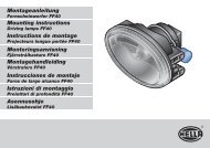
FunctionaldescriptionVehicle headlights mustguarantee sufficient visibilityand yet must not dazzleoncoming road users. For thisreason, their alignment mustbe checked and/or adjustedat regular intervals. Differentcountries have different legalregulations in this respect.Beamsetter <strong>SEG</strong> <strong>IV</strong>-C iscontrolled by micro-processor.A camera, which is installedin the beamsetter box, filmsthe headlight image. Theheadlight setting can bechecked on the basis of theoptical display unit.The beamsetter <strong>SEG</strong> <strong>IV</strong>-C canbe used both to check thealignment of vehicleheadlights and to set them.The beamsetter is equippedwith an "acoustic + opticalsetting mode" for fast andconvenient headlightadjustment.F1F4
Technical dataArea of applicationParaboloidHeadlight typesthat can be testedProjection system (DE or PES)Free-form (FF or HNS)XENON and LEDMeasuring rangeAbove 0 - 300 mm / 10m (0 - 3%)Below 0 - 500 mm / 10m (0 - 5%)Left 0 - 1000 mm / 10m (0 - 10%)Right 0 - 1000 mm / 10m (0 - 3%)Adjusting range centreof lens/groundMeasuring distance250 - 1450 mm300 - 700 mmIntensityLuminous intensityIlluminance0 - 125,000 Candela (cd)0 - 200 Lux (lx)Fault limitsIntensity +/- 5%Deviation from the axle +/- 5’Working rangeTemperature-15∞C to +45∞CRelative humidity 20 - 80%Voltage supplyMains adapterBattery operation100 - 240 V, 50/60 Hz AC12 V DCLaser sight vaneVoltage supply9V block battery (not included in the scope of supply)Protective rating 25Dimensions<strong>SEG</strong> (W x H x D)622 x 1680 x 658 mm
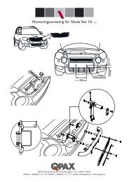
Assembly1 Insert column with2 pressure disc3 and clamping piece in4 the bushing.1110The colour markings onthe column and base mustbe above one another.5 Drive the dowel pin intothe column bore hole until thetwo projecting ends are thesame length.6 Set the beamsetter boxin place as shown in thediagram, with the7 actuating button pressed,and lower to working height.8 Set the sight vane holderonto the column and tightenusing the9 clamping wheel.Push the hand wheel 10firmly onto the hexagonalrod at the top end of thecolumn and secure usinga circlip 11 .19876Opening to adjust thecolumn guide using anAllen key size 6.Only necessary if thecolumn guide has toomuch play.35246
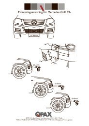
Product detailsMechanism1 Hand wheel for fixing thecolumn in place2 Hand wheel for sightvane holder3 Column allows adjustmentof the beamsetter box from250 mm - 1450 mm4 Actuating button formoving the beamsetter boxupwards and downwards5 Compartment with Velcrofastening for mains connectionand battery charging6 Sight vane holder7 Switch for laser sight vane8 Laser sight vane withclamping screw9 Operating panel with LCDdisplay10 Diagonal mirror withsetting wheel11 Tape measure12 Fresnel lens13 Unit base with rubbercasters for use on suitablefloor spaces or rails14 LED optical setting mode12345678910141112Note!Scratched lenses must bereplaced. Scratches canhave a negative influenceon the image on the screen."Only use a soft cloth andglass cleaner to clean thelens."After the lens has beenreplaced, the <strong>SEG</strong> <strong>IV</strong>-Cmust be readjusted.137
Operating panelDescription ofthe key functionsThe software version of the<strong>SEG</strong> <strong>IV</strong>-C appears in thedisplay when the beamsetteris switched on, e.g. Version0.25 GE from June 2005.F1 F2 F3F4To change the languageof the beam setter,please look on page28-30 (language setting,page 30, point 12).Key high beam right (in direction of travel)Key low beam rightKey high beam left (in direction of travel)Key low beam leftKey fog light rightKey fog light leftKey daytime running light rightKey daytime running light leftLCD displayOperating keyson the LCD displayF1 F2 F3F4Operating keyson the LCD displayHELLA <strong>SEG</strong> <strong>IV</strong>-CLCD displayMain menuPlease selectMESS JUST GW OFFMENUF1 F2 F3 F4Main menuService menuDisplay contrast ENTER ESCService menu:Contrast settingRight high beamHotspot: 6.7 %Hotspot: 3.4 %Intensity:24 lxInt. Hotspot:30 lxGRAF SEND ESCOK24 lx1.2 %MSW SEND ESC8Checking the right high beamAdjusting the headlightAdjusting the headlight
Test areaMobile <strong>SEG</strong> <strong>IV</strong>-CLevel floor space (accordingto ISO 10 604 for mobile <strong>SEG</strong><strong>IV</strong>-C)Note!The state and conditionof the floor spaces aredecisive for correct headlightbeam setting.Unevennessof the ground≤ 0.5 mm/mWRONGCars min. 4 m / Trucks min. 8.5 mUnevenness of the ground and tilt≤ 1 mm/m according to ISO 10 604WRONGStationary <strong>SEG</strong> <strong>IV</strong>-C1Max.difference inheight 0.5 mmThe Hella beamsetters havealso been designed forstationary installation.The rails are fixed to theground.When the unit is to be usedas a stationary unit, a set ofrails (Hella part no. 9XS 861736-001) must be ordered forevery Hella beamsetter. Therail itself can be used as adrilling template for the holesrequired to fix it in place.For the floor space, the sameapplies as described undermobile <strong>SEG</strong> <strong>IV</strong>-C.To be able to check and adjustthe headlights exactly, thefollowing must be observedwhen laying the rails:Vehicle floor space and raillevel for the beamsetter mustbe parallel in both extensions.The difference in heightbetween rail running surfacesmust not exceed 0.5 mm(Fig. 1).The rails must be in contactwith the ground over theirwhole length so that theycannot become bent.The rails are laid in pairs at90∞ to the vehicle'slongitudinal axis.<strong>Off</strong>set must be avoided at railjoints (Fig. 2).2SpacersRail joint without offsetRolled section9
Set-up andalignmentPreparing the vehicleThe tyres must have theprescribed pressure!The vehicle must be loadedas follows:a) Cars, with one person or75 kg on the driver seat withthe vehicle otherwiseunloaded.b) Trucks and other multi-trackvehicles are to be withoutload.c) Single-track vehicles as wellas single-axle traction orworking machines (with seatcart or trailer): with one personor 75 kg on the driver seat.In the case of hydraulic or airsuspension the engine has torun at medium speed until theheight of the vehicle no longerchanges.If automatic correction of theheadlight or an infinite or 2-stage setting fixture isavailable, heed themanufacturer's instructions.National regulations mustalways be heeded.Setting up the <strong>SEG</strong> <strong>IV</strong>-CDevices with caster basesmust be aligned individuallyfor each headlight to betested. Units on rails only needto be aligned once for eachvehicle.Pull out the integrated tapemeasure. Check the distancefrom the front edge of thebeamsetter box to theheadlight. (approx. 30 cm tomax. 70 cm)30 - 70 cmFix the sight vane holder inplace at the top end of thecolumn.The spots sighted on thevehicle must be significantlylower than the height of thesight vane.Release the column fixingmechanism.Switch on the laser.Align the laser sight vane insuch a way that the lasertouches two points at thesame height and symmetricalto the longitudinal axis of thevehicle.Tighten the column fixingmechanism without shiftingthe alignment.Release the clamping screwto move the laser sight vaneto the right or left for easiersighting.10
Set-up andalignmentAlignment when the frontof the vehicle is extremelyvaultedIf alignment is difficult in individualcases of commercialvehicles and buses withextremely vaulted front ends,the centres of the headlightsmust be transferred to thefloor using a plumb bob orother suitable object andrecorded using the sight vane.11
Checking orsetting headlightsIn the case of vehicles withautomatic compensation oftilt in body or headlight causedby dependence on load, thecharacteristics of thesemechanisms must be heededaccording to themanufacturer's instructions.In the case of vehicles wherethe headlights can be adjustedby hand, the adjustmentfeature must notched in theprescribed basic position.In the case of headlightswhich can only be adjustedto 2 positions where thenotched positions are notmarked, proceed as follows:With vehicles where the lightbeam rises as load increases,carry out the headlight settingin the final position of theadjustment feature where thelight beam is in its highestposition.With vehicles where the lightbeam falls as load increases,carry out the headlight settingin the final position of theadjustment feature where thelight beam is in its lowestposition.e = Dimension e.g. 10cm =1.0%, by which the cut-offline has to be inclined at adistance of 10 m.H = Height of the centre ofthe headlight above the floorspace in cm.H = Height of the testing arealine above the floor space incm.Note for vehicles where theupper headlight mirror edgeis higher than 145 cm abovethe floor spaceThe vehicle must be set up ona level surface that does nothave to be horizontal at adistance of 10 m from avertical light-coloured wall.Draw the following lines onthe testing wall:Line A:Extend the vehicle'slongitudinal axis to the testingwall and mark it by a verticalline.Line B and C:Measure distance X of theheadlights (centre to centre)on the vehicle and mark thedimension symmetrical toline A.Mark at the distance "e" underthe line H.With headlights„e” = H cm,3With fog lights„e” = H + 7 cm3Linie H:Measure the height headlightcentre - floor space and markit on the testing wall parallelto the floor space.Setting the headlightsCover the right headlight andset the left one in such a waythat the horizontal part of thecut-off line touches line D.Then align the headlightsideways.The bend between thehorizontal and rising part ofthe cut-off line must be on lineB.Then set the right headlight inexactly the same way. In thiscase, the salient point in thecut-off line is on line C.12
Definitionof termsLow beamA Cut-off lineBorder of the light distributionbetween "top dark" and"bottom light" with low-beamlight.B Salient pointSalient point of the cut-off linewith asymmetrical low beam.The deviation of the salientpoint is converted to %. 10 mis used as a referenceparameter.Yaw angleAngle between the part of thecut-off line rising to the rightof the salient point and thehorizontal with low-beam light.The rise of the yaw anglediffers depending on theheadlight design (two differenttypes are possible).Fog lightsAngle of rollAngle between the left part ofthe cut-off line and thehorizontal, usually 0°.High beamC Central markThe deviation of the hot-spotin x-direction and y-directionis given from the central markas reference point.D Hot-spotCentre focus of the highbeam. The deviation of thehot-spot from the central markis converted to %. 10m isused as a referenceparameter.IlluminanceLuminous intensityThe illuminance and lightintensity are given in Lux orCandela.Conversion: Illuminance tolight intensity.E = Illuminance in LuxI = Luminous intensity inCandelaI = E · r 2r = Measuring distanceeadlights at 25 m.Nodding angleThe angle between theheadlight beam focus and theroad surface is expressed inpercent, the referenceparameter 10 m is used.+%-%13
OperationSwitching on the<strong>SEG</strong> <strong>IV</strong>-CThe software version numberis displayed.The <strong>SEG</strong> <strong>IV</strong>-C can beswitched on by pressing anykey.HELLA <strong>SEG</strong> <strong>IV</strong>-CThe main menu appears about1 second later.Main menuPlease selectMESS JUST GW OFFMENUF1 F2 F3 F4Switching off the<strong>SEG</strong> <strong>IV</strong>-CThe <strong>SEG</strong> <strong>IV</strong>-C switches offautomatically when theswitch-off time has expired.The switch-off time is set withthe user variable 5 (standardsetting: 10 minutes). The <strong>SEG</strong><strong>IV</strong>-C switches off if no key ispressed during this time.OrF41 Press the F4 key for atleast 2 seconds.Main menuPlease selectMESS JUST GWMENUOFFF1 F2 F3 F4F32 Then press the F3 key toswitch off the <strong>SEG</strong> <strong>IV</strong>-C.Service menu<strong>SEG</strong> <strong>IV</strong>-C switch off ENTER ESC14
OperationMenu overviewAn LCD display and operatingkeys are used to operate the<strong>SEG</strong> <strong>IV</strong>-C.The main menu comprises 4programs:MeasurementMain menuMESS JUST GW OFFMENUF1 F2 F3 F4AdjustmentLimit value menuOFF / Service menu- Default limit values- Low beam SAE/EC- Left-hand / right-hand trafficSwitch off the <strong>SEG</strong> <strong>IV</strong>-CDisplay contrastEEPROM variables- User variables- Limit valuespassenger cars / trucks- System variables (password)AD converter valuesCalibrate camera (password)- Zero point- Resolution- Intensity15
OperationMeasurementThis menu item is used tocheck the headlights(headlight diagnosis).F1F2F31 Switch headlight on.F42 Press the F1 key to carryout headlight diagnosis.Main menuPlease selectMESS JUST GWMENUOFFF1 F2 F3 F4The following window willappear with the pre-setreference values:Reference values3 The reference value can bereduced or increased usingkeys F1 and F2 (press briefly).4 Key F3 (press briefly) is usedto select the headlight type.5 Keep the F1 key pressedlonger to switch over to truckreference values.6 Keep the F2 key pressedlonger to switch over topassenger car referencevalues.7 Keep the F3 key pressedlonger to switch over to lefthandtraffic.-1.3%EC ESCThe reference valuesare taken over for futuremeasurements.8 Press the required testingkey on the operating panel.The built-in camera thendigitalises the headlight imagedepicted on the projectionscreen.High beamLow beamFog light16Daytime running light
OperationMeasurementThe key functions are identicalfor the following windows:F2F2: Switch between graphicaland numerical evaluation (see"Measurement" section).F4F4: Leave windowHigh beamThe image of the headlightappears on the display.- The left-hand window showsthe setting direction.- The reference window is inthe middle.- The actual position of theheadlight is shown as a blackbox.Hot-spot x: Position of thehot-spot in the x-direction in%Hot-spot y: Position of thehot-spot in the y-direction in%Intensity: <strong>Light</strong> intensity of thecentral point in LuxInt. hot-spot: <strong>Light</strong> intensityin the hot-spot in Luxl: 24.0 luxH: 24.0 luxMSW SEND ESCHigh beam rightHotspot x: 1.0 %Hotspot y: 0.8 %Intensity:24.0 lxInt. Hotspot:42.0 lxGRAF SEND ESCLow beamThe image of the headlightappears on the display.- The upper window showsthe setting direction.- The reference corridor is inthe middle.- The actual position of theheadlight is shown as a thickblack line.Nodding angle:Nodding angle in %G: Yaw angle in ∞R: Angle of roll in ∞KP: Salient point,X: in x-directionY: in y-directionIntensity:<strong>Light</strong> intensity in LuxGlare:Glare intensity in LuxLow beam right-1.3%25.0 lux-1.2 %MSW SEND ESCSW:Nodding angle: -1.2 %G: 12.0° R:0.0%KP: X: 1.3% Y: 0.5%Intensity:Glare:25.0 lx1.0 lxGRAF SEND ESC17
OperationMeasurementThe key functions are identicalfor the following windows:F2F2: Switch between graphicaland numerical evaluation (see"Measurement" section).F4F4: Leave window.Fog lightThe image of the headlightappears on the display.- The upper window showsthe setting direction.- The reference corridor is inthe middle.- The actual position of theheadlight is shown as a thickblack line.Nodding angle: Nodding anglein %Angle of roll: Angle of roll in ∞Intensity:<strong>Light</strong> intensity in LuxGlare:Glare intensity in Lux24.0 lux2.0 %MSW SEND ESCLow beam rightSW:-1.3%Nodding angle: 2.0 %Angle of roll:Intensity:1.0°24.0 lxGlare:1.0 lxGRAF SEND ESC18Auxiliary light(daytime running light)The image of the headlightappears on the display.- The left-hand window showsthe setting direction.- The reference window is inthe middle.- The actual position of theheadlight is shown as a blackbox.Hot-spot x: Position of thehot-spot in the x-direction in%Hot-spot y: Position of thehot-spot in the y-direction in%Intensity: <strong>Light</strong> intensity of thecentral point in LuxInt. hot-spot: <strong>Light</strong> intensityl: 24.0 luxH: 42.0 luxMSW SEND ESCAuxiliary light rightHotspot x: 1.0 %Hotspot y: 0.8 %Intensity:24.0 lxInt. Hotspot:42.0 lxGRAF SEND ESC
OperationAdjustmentThis menu item is usedto set the headlights.1 Switch headlight on.F22 Press the F2 key to adjustthe headlights.Main menuPlease selectMESS JUST GW OFFMENUF1 F2 F3 F4The following window willappear with the pre-setreference values:F13 The reference value can bereduced or increased usingkeys F1 and F2 (press briefly).F3F24 Key F3 (press briefly) is usedto select the headlight type.Reference values-1.3% EC ESCF15 Keep the F1 key pressedlonger to switch over to truckreference values.F37 Keep the F3 key pressedlonger to switch over to lefthandtraffic.F26 Keep the F2 key pressedlonger to switch over topassenger car referencevalues.8 Press the required testingkey on the operating panel.The built-in camera thendigitalises the headlight imagedepicted on the projectionscreen.The reference valuesare taken over for futuremeasurements.High beamLow beamFog light19Daytime running light
OperationAdjustmentThe key functions are identicalfor the following windows:F1F1: Selection menu for theacoustic setting mode (see"Acoustic setting mode"section).F2F2: Switch between graphicaland numerical evaluation (see"Measurement" section).F4F4: Leave window.High beam1 The image of the headlightappears on the display.- The left-hand window showsthe setting direction.- The reference window is inthe middle.- The actual position of theheadlight is shown as ablack box.2 Adjust the headlight until theblack box is in the referencewindow."OK" will then appear in theleft-hand window.3 Press the F4 key to leavethis window.OKl: 2.1 luxH: 10.3 luxMSW SEND ESCl: 2.1 luxH: 10.3 luxMSW SEND ESCLow beam1 The image of the headlightappears on the display.- The upper window showsthe setting direction.- The reference corridor is inthe middle.- The actual position of theheadlight is shown as a thickblack line.2.4 lux0.8 %MSW SEND ESC2 Adjust the headlight until thethick black line is in thereference corridor. "OK" willthen appear in the upperwindow.3 Press the F4 key to leavethis window.OK24 lx1.2 %MSW SEND ESC20
OperationAdjustmentThe key functions are identicalfor the following windows:F1F1: Selection menu for theacoustic setting mode (see"Acoustic setting mode"section).F2F2: Switch between graphicaland numerical evaluation (see"Measurement" section).Fog light1 The image of the headlightappears on the display.- The left-hand window showsthe setting direction.- The reference corridor is inthe middle.- The actual position of theheadlight is shown as ablack box.2 Adjust the headlight until thethick black line is in thereference corridor."OK" will then appear in theupper window.3 Press the F4 key to leavethis window.OK1.3 lux2.0 %MSW SEND ESC1.3 lux2.0 %F4F4: Leave window.MSW SEND ESCAuxiliary light (daytimerunning light)1 The image of the headlightappears on the display.- The left-hand window showsthe setting direction.- The reference window is inthe middle.- The actual position of theheadlight is shown as ablack box.l: 2.1 luxH: 10.3 luxMSW SEND ESC2 Adjust the headlight until theblack box is in the referencewindow."OK" will then appear in theleft-hand window.3 Press the F4 key to leavethis window.OKl: 2.1 luxH: 10.3 luxMSW SEND ESC21
OperationAdjustmentAcoustic setting modeThe <strong>SEG</strong> <strong>IV</strong>-C is equippedwith an "acoustic and opticalsetting mode" (LED in front ofthe LCD display) which worksas follows:The more the actual positionof the headlight deviates fromthe reference position, theslower the acoustic signal andthe LED flashing will become.As the actual positionapproaches the referenceposition, the acoustic signaland the flashing frequencyincrease.1 Select the vertical acousticsetting mode by pressing theF1 key.2 Adjust the headlightvertically until a continuousacoustic signal can be heard.3 Select the horizontalacoustic setting mode bypressing the F1 key.4 Adjust the headlighthorizontally until a continuousacoustic signal can be heard."OK" will then appear in theleft-hand window.5 Press the F1 key again toswitch off the setting mode.l: 2.1 luxH: 10.3 luxMSW SEND ESCl: 2.1 luxH: 10.3 luxWhen the actual positionreaches the referenceposition, a continuousacoustic signal is heard andthe LED remains lit.If necessary, the acousticsetting mode can be switchedoff.Display descriptionF1The vertical acoustic settingmode is activated by pressingthe F1 key.F1OKMSW SEND ESC2.1 luxH: 10.3 luxMSW SEND ESCThe horizontal acoustic settingmode is activated by pressingthe F1 key.F1The acoustic setting mode isswitched off by pressing theF1 key.22
OperationLimit value menuThe beamsetter <strong>SEG</strong> <strong>IV</strong>-C canbe pre-set for testing variousheadlight designs.These pre-set values thenappear every time thebeamsetter is switched on.• Passenger cartruck• European asymmetricalRight-Left-hand traffichand trafficRequest limit value menu asdescribed below:F31 Press key F3 to enter thelimit value menu.2 The <strong>SEG</strong> <strong>IV</strong>-C is now in thelimit value menu. The limitvalue menu comprises 3programs:- Default limit values- Low beam EC- Left-hand / right-hand trafficMain menuPlease selectMESS JUST GW OFFMENUF1 F2 F3 F4Selection menueDefault limit values ENTER ESCF1F2F33 These programs can beselected using the F1 and F2keys and requested bypressing F3.F44 Press the F4 key to leavethe menu item or limit valuemenu.F35 The F3 key is pressed toselect the required menu pointor save the change.23
OperationLimit value menuLimit valuespassenger cars / trucks1 Request the limit value menuand select the menu item"Default limit values".F32 Press the F3 key to requestthe passenger car/truckselection menu.Selection menueDefault limit values ENTER ESCThe passenger car/truckselection menu appears onthe display:F13 Select the requiredpassenger car/truck limitvalues by pressing the F1 andF2 keys.F3F2Main menuPlease selectENTERESC4 Use the F3 key to save theselected limit values and leavethe menu item.F1 F2 F3 F4F45 Press the F4 key to leavethe menu item without savingthe values.Example:Default limit values Passenger car TruckLow beam - 1.3% - 3.1%High beam 0.0% 0.0%Fog light - 2.0% - 4.0%For motor vehicles with lighting mounted according to76/756 EEC or with approval according to ECE-R 48, thesetting dimensions given on the vehicle must be heeded.24
EuropeanheadlightsLimit value menu1 Request the limit value menuand select the menu item"Low beam EC".F32 Press the F3 key to requestthe headlight selection menu.Select menuLow beam EC ENTER ESCThe headlight selectionmenu appears on thedisplay:3 Headlight selection menu:- European asymmetricheadlightLow beamF1F2European asymmetric4 Select the required headlighttype by pressing the F1 andF2 keys. ENTER ESCF35 Use the F3 key to save theselected headlight type andleave the menu item.F46 Press the F4 key to leavethe menu item without savingthe values.25
OperationLimit value menuLeft-hand /right-hand traffic1 Request the limit value menuand select the menu item"Left-hand/right-hand traffic".F32 Press the F3 key to requestthe left-hand/right-hand trafficselection menu.Select menuLeft / right-hand traffic ENTER ESCThe left-hand traffic/right-handtraffic selection menu appearson the display:F13 Use the F1 and F2 keys tochoose between left-hand andright-hand traffic.F3F24 Use the F3 key to save theselected option and leave themenu item.Limit valuesPlease selectENTERESCF1 F2 F3 F4F45 Press the F4 key to leavethe menu item without savingthe values.left-hand trafficright-hand traffic26
OperationService menuThe beamsetter isprogrammed in thefactory. Changing the setvariables can lead to thebeamsetter no longerfunctioning properly.Request the service menuas described below:F41 Press the F4 key for at least»2 seconds« to enter theservice menu.2 The <strong>SEG</strong> <strong>IV</strong>-C is nowin the service menu.The service menu comprises5 programs:- Switch off the <strong>SEG</strong> <strong>IV</strong>-C- Set display contrast- EEPROM variables- AD converter values- Calibrate camera(password)Main menuPlease selectMESS JUST GW OFFMENUF1 F2 F3 F4Service menu<strong>SEG</strong> <strong>IV</strong>-C switch off ENTER ESCF1F2F33 These programs can beselected using the F1 and F2keys and requested bypressing F3.F44 Press the F4 key to leavethe menu item or the servicemenu.F35 The F3 key is pressed toselect the required menu pointor save the change.27
OperationF1F2F3F4Service menuThe display contrast istemperature-dependentand is automaticallycorrected through internaltemperature monitoringso that the contrastsetting remains constantover almost the wholeoperating temperaturerange.28Set contrast1 Request the service menuand select the menu item"Display contrast".2 Press the F3 key to requestthe contrast program. Thecontrast program appears onthe display:3 Press the F1 and F2 keys toreduce or increase the displaycontrast.4 Use the F3 key to save theset contrast and leave themenu item.5 Press the F4 key to leavethe menu item without savingthe values.Programme variables1 Request the service menuand select the menu item"EEPROM variables".2 Press the F3 key to requestthe EEPROM variablesprogram.The EEPROM variablesprogram appears on thedisplay:3 The EEPROM variablesprogram comprises 3programs:- User variables- Limit valuespassenger cars / trucks- System variables(password)4 These programs can beselected using the F1 and F2keys and requested bypressing F3.Service menuDisplay contrast ENTER ESCService menuContrastOK ESCService menuEEPROM variables ENTER ESCEEPROM MenuUser variables ENTER ESC
OperationF1F2F3F4Service menu5 The digit on the left of thedisplay indicates the variablenumber, the digit on the rightindicates the variable setting.6 Request the requiredvariable by pressing the F1and F2 keys.7 Select the variable to bechanged by pressing the F3key.8 Enter a new variable valueusing the input keys.An incorrect entry can becorrected by briefly pressingthe F4 key during input of thevariables.9 Keep the F4 key pressedsomewhat longer for the inputvalue to made negative.10 Keep the F3 key pressedsomewhat longer to store theinput value.11 Press the F3 key briefly toleave the menu item withoutsaving the values.EEPROM variablesSwitch-off timeVar 5: 1 EDIT ESCEEPROM variablesSwitch-off timeVar 5: 1New value: 5ENTERESCAssignment of the digitsto the input keys:0246F1 F2 F3F48 91357press briefly = deletepress longer = negative value29press briefly = leave without savingpress longer = save value
OperationService menuUser variablesNo. Name of the EEPROM user variables Default value Min Max0 Version number 01 Test line number 02 Percent or degrees 00 = Percent1 = Degrees3 Lux or Candela 00 = Lux1 = Candela4 Acoustic signal 10 = Acoustic signal off1 = Acoustic signal on5 Switch-off time in minutes 10 0 655351 = 1 minute6 Limit value menu before measurement 17-9 not used -112 Language 00 = German GE1 = English GB13 not used14 Delete measured values 00 = Yes1 = No15 Passenger car or truck after switch-on 00 = Passenger car1 = Truck16 Right-hand traffic or left-hand traffic after switch-on 00 = Right-hand traffic1 = Left-hand traffic17 Selection of type: 00 = Asymmetrical European low beam18-29 not used -130 Display contrast 35031 Reference value passenger car in 0.1% -1232 Reference value truck in 0.1% -3033-48 not used -149 EEPROM not empty, pattern for user variables 2320530
OperationService menuLimit valuespassenger cars / trucks1 Request the service menuand select the menu item"EEPROM variables".F32 Press the F3 key to requestthe EEPROM variablesprogram.Service menuEEPROM variables ENTER ESCThe EEPROM variablesprogram appears on thedisplay:F1F2F33 Select the limit valuespassenger car/truck using theF1 and F2 keys and requestthem by pressing F3.EEPROM MenuLimit valuespassenger car/truck ENTER ESCThe limit values programappears on the display:4 The limit values programcomprises 4 programs:- Limit values passengercars right-hand traffic- Limit values trucksright-hand traffic- Limit values passengercars left-hand traffic- Limit values trucks lefthandtrafficEEPROM limit valuesLimit values passengercars right-hand traffic ENTER ESC31
OperationService menuLimit values„Passenger cars / trucks”F1 F2 F35 These programs can beselected using the F1 and F2keys and requested bypressing F3.6 The digit on the left of thedisplay indicates the variablenumber, the digits on the rightindicate the variable settings.EEPROM variablesUpper limit high beamVar 200: 15 ENTER ESCF17 Select the required variableby pressing the F1 and F2keys.F3F28 Select the variable to bechanged by pressing the F3key.9 Enter a new variable valueusing the input keys.EEPROM variablesUpper limit high beamVar 200: 15New value: 13 ENTER ESCF4An incorrect entry can becorrected by briefly pressingthe F4 key during input of thevariables.F410 Keep the F4 key pressedsomewhat longer for the inputvalue to made negative.32
OperationService menuLimit values„Passenger car”right-hand trafficRight-hand trafficNo. Name of the variable Default value Min Max200 Upper limit high beam in 0.1% 15201 Lower limit high beam in 0.1% 10202 Right limit high beam in 0.1% 20203 Left limit high beam in 0.1% 20204 Intensity of high beam in 0.1 Lux 80205-209 not used -1210 Upper limit low beam in 0.1% -7211 Lower limit low beam in 0.1% -19212 Right limit low beam in 0.1% 8213 Left limit low beam in 0.1% -8214 Intensity of low beam in 0.1 Lux 160215 Glare of low beam in 0.1 Lux 10216-219 not used -1220 Upper limit fog light in 0.1% -15221 Lower limit fog light in 0.1% -25222 Intensity of fog light in 0.1 Lux 160223 Glare of fog light in 0.1 Lux 10224 not used -1225 Upper limit auxiliary light in 0.1% 15226 Lower limit auxiliary light in 0.1% 10227 Right limit auxiliary light in 0.1% 20228 Left limit auxiliary light in 0.1% 20229 Intensity of auxiliary light in 0.1 Lux 480245-248 not used -1249 EEPROM not empty, pattern for limit valuespassenger car right-hand traffic 2320533
OperationService menuLimit valuesTruck right-hand trafficRight-hand trafficNo. Name of the variables Default value Min Max250 Upper limit high beam in 0.1% 15251 Lower limit high beam in 0.1% 10252 Right limit high beam in 0.1% 20253 Left limit high beam in 0.1% 20254 Intensity of high beam in 0.1 Lux 480255-259 not used -1260 Upper limit low beam in 0.1% -25261 Lower limit low beam in 0.1% -37262 Right limit low beam in 0.1% 8263 Left limit low beam in 0.1% -8264 Intensity of low beam in 0.1 Lux 160265 Glare of low beam in 0.1 Lux 10266-269 not used 1270 Upper limit fog light in 0.1% 35271 Lower limit fog light in 0.1% -45272 Intensity of fog light in 0.1 Lux 160273 Glare of fog light in 0.1 Lux 10274 not used -1275 Upper limit auxiliary light in 0.1% 15276 Lower limit auxiliary light in 0.1% -10277 Right limit auxiliary light in 0.1% 20278 Left limit auxiliary light in 0.1% -20279 Intensity of auxiliary light in 0.1 Lux 480295-298 not used -1299 EEPROM not empty, pattern for limit valuestruck right-hand traffic 2320534
OperationService menuLimit values„Passenger car”left-hand trafficLeft-hand trafficNo. Name of the variables Default value Min Max300 Upper limit high beam in 0.1% 0301 Lower limit high beam in 0.1% -20302 Right limit high beam in 0.1% 0303 Left limit high beam in 0.1% -20304 Intensity of high beam in 0.1 Lux 480305-309 not used -1310 Upper limit low beam in 0.1% -5311 Lower limit low beam in 0.1% -20312 Right limit low beam in 0.1% 0313 Left limit low beam in 0.1% -20314 Intensity of low beam in 0.1 Lux 160315 Glare of low beam in 0.1 Lux 10316-319 not used -1320 Upper limit fog light in 0.1% -15321 Lower limit fog light in 0.1% -25322 Intensity of fog light in 0.1 Lux 160323 Glare of fog light in 0.1 Lux 10324 not used -1325 Upper limit auxiliary light in 0.1% 0326 Lower limit auxiliary light in 0.1% -20327 Right limit auxiliary light in 0.1% 0328 Left limit auxiliary light in 0.1% -20329 Intensity of auxiliary light in 0.1 Lux 480345-348 not used -1349 EEPROM not empty, pattern for limit valuespassenger car right-hand traffic 2320535
OperationService menuLimit valuesTruck left-hand trafficLeft-hand trafficNo. Name of the variables Default value Min Max350 Upper limit high beam in 0.1% 0351 Lower limit high beam in 0.1% -20352 Right limit high beam in 0.1% 0353 Left limit high beam in 0.1% -20354 Intensity of high beam in 0.1 Lux 480355-359 not used -1360 Upper limit low beam in 0.1% -5361 Lower limit low beam in 0.1% -20362 Right limit low beam in 0.1% 0363 Left limit low beam in 0.1% -20364 Intensity of low beam in 0.1 Lux 160365 Glare of low beam in 0.1 Lux 10366-369 not used -1370 Upper limit fog light in 0.1% -15371 Lower limit fog light in 0.1% -25372 Intensity of fog light in 0.1 Lux 160373 Glare of fog light in 0.1 Lux 10374 not used -1375 Upper limit auxiliary light in 0.1% 0376 Lower limit auxiliary light in 0.1% -20377 Right limit auxiliary light in 0.1% 0378 Left limit auxiliary light in 0.1% -20379 Intensity of auxiliary light in 0.1 Lux 480395-398 not used -1399 EEPROM not empty, pattern for limit valuestruck left-hand traffic 2320536
Spare parts1Hand wheel for sightvane holder9SG 855 498-0012Hand wheel for columnfixing mechanism9SG 855 454-011123Key9ST 861 074-0014Viewing glass9EV 861 038-0017435Caster replacement setcomprising 3 casters9XS 862 004-0016Clamping piece for column9XD 857 744-0017Column with fixingmechanism8XT 861 234-021Further spare parts areavailable. Replacementrequires re-adjustment ofthe beamsetter and iscarried out by properlyequipped Hella agents.6537
MaintenanceThe beamsetter <strong>SEG</strong> <strong>IV</strong>-C isan optical measuring unit andshould be treated accordingly.The beamsetter lens shouldbe wiped over regularly witha clean cloth.Care must be taken that thelens does not becomescratched.Otherwise the beamsetter<strong>SEG</strong> <strong>IV</strong>-C is maintenance-free.Charging the batteryRemove the cap (Velcrofastening)Remove the plug and connectto a 100V-240V AC socket.Message on the display<strong>SEG</strong> <strong>IV</strong>-C StatusBattery chargingReplacing the laser sightvane batteryReplace the battery when lightintensity decreases.38 © Hella KGaA Hueck & Co., D-59552 Lippstadt 460 816-24 10.08 Printed in Germany