Sym GTS servicemanual - Scootergrisen
Sym GTS servicemanual - Scootergrisen
Sym GTS servicemanual - Scootergrisen

You also want an ePaper? Increase the reach of your titles
YUMPU automatically turns print PDFs into web optimized ePapers that Google loves.
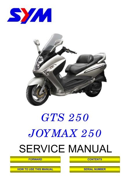
<strong>GTS</strong> 250<br />
JOYMAX 250<br />
SERVICE MANUAL<br />
FORWARD<br />
HOW TO USE THIS MANUAL<br />
CONTENTS<br />
SERIAL NUMBER
Homepage<br />
Contents<br />
Page Content Index<br />
1-1 ~ 1-16 General Information 1<br />
2-1 ~ 2-18 Service Maintenance Information 2<br />
3-1 ~ 3-8 Lubrication System 3<br />
4-1 ~ 4-14 Fuel System 4<br />
5-1 ~ 5-10 Engine Removal 5<br />
6-1 ~ 6-16 Cylinder Head / Valve 6<br />
7-1 ~ 7-8 Cylinder / Piston 7<br />
8-1 ~ 8-14 “V” Type Belt Driving System / Kick-Starter 8<br />
9-1 ~ 9-8 Final Driving Mechanism 9<br />
10-1 ~ 10-10 Alternator 10<br />
11-1 ~ 11-8 Crankshaft / Crankcase 11<br />
12-1 ~ 12-14 Cooling System 12<br />
13-1 ~ 13-14 Body Cover 13<br />
14-1 ~ 14-12 Front Brake / Front Wheel 14<br />
15-1 ~ 15-10 Steering / Front Cushion 15<br />
16-1 ~ 16-6 Rear Brake / Rear Wheel / Rear Cushion 16<br />
17-1 ~ 17-24 Electrical Equipment 17<br />
18-1 ~ 18-2 Electrical Diagram 18
Serial Number<br />
Home page Contents
Service Precautions<br />
� Always use with SANYANG genuine parts and<br />
recommended oils. Using non-designed parts<br />
for SANYANG ATV may damage the ATV.<br />
� Special tools are designed for remove and<br />
install of components without damaging the<br />
parts being worked on. Using wrong tools may<br />
result in parts damaged.<br />
� When servicing this ATV, use only metric tools.<br />
Metric bolts, nuts, and screws are not<br />
interchangeable with the English system, using<br />
wrong tools and fasteners may damage this<br />
vehicle.<br />
� Clean the outside of the parts or the cover<br />
before removing it from the ATV. Otherwise, dirt<br />
and deposit accumulated on the part's surface<br />
may fall into the engine, chassis, or brake<br />
system to cause damage.<br />
� Wash and clean parts with high ignition point<br />
solvent, and blow dry with compressed air. Pay<br />
special attention to O-rings or oil seals because<br />
most cleaning agents have an adverse effect on<br />
them.<br />
To this chapter contents<br />
1. General Information<br />
� Never bend or twist a control cable to prevent<br />
unsmooth control and premature worn out.<br />
� Rubber parts may become deteriorated when<br />
old, and prone to be damaged by solvent and oil.<br />
Check these parts before installation to make<br />
sure that they are in good condition, replace if<br />
necessary.<br />
� When loosening a component which has<br />
different sized fasteners, operate with a<br />
diagonal pattern and work from inside out.<br />
Loosen the small fasteners first. If the bigger<br />
ones are loosen first, small fasteners may<br />
receive too much stress.<br />
� Store complex components such as<br />
transmission parts in the proper assemble order<br />
and tie them together with a wire for ease of<br />
installation later.<br />
� Note the reassemble position of the important<br />
components before disassembling them to<br />
ensure they will be reassembled in correct<br />
dimensions (depth, distance or position).<br />
� Components not to be reused should be<br />
replaced when disassembled including gaskets<br />
metal seal rings, O-rings, oil seals, snap rings,<br />
and split pins.<br />
1-3
1. General Information<br />
� The length of bolts and screws for assemblies,<br />
cover plates or boxes is different from one<br />
another, be sure they are correctly installed. In<br />
case of confusion, Insert the bolt into the hole to<br />
compare its length with other bolts, if its length<br />
out side the hole is the same with other bolts, it<br />
is a correct bolt. Bolts for the same assembly<br />
should have the same length.<br />
� Tighten assemblies with different dimension<br />
fasteners as follows: Tighten all the fasteners<br />
with fingers, then tighten the big ones with<br />
special tool first diagonally from inside toward<br />
outside, important components should be<br />
tightened 2 to 3 times with appropriate<br />
increments to avoid warp unless otherwise<br />
indicated. Bolts and fasteners should be kept<br />
clean and dry. Do not apply oil to the threads.<br />
� When oil seal is installed, fill the groove with<br />
grease, install the oil seal with the name of the<br />
manufacturer facing outside, and check the<br />
shaft on which the oil seal is to be installed for<br />
smoothness and for burrs that may damage the<br />
oil seal.<br />
1-4<br />
To this chapter contents<br />
Manufacturer's name<br />
� Remove residues of the old gasket or sealant<br />
before reinstallation, grind with a grindstone if<br />
the contact surface has any damage.<br />
� The ends of rubber hoses (for fuel, vacuum, or<br />
coolant) should be pushed as far as they can go<br />
to their connections so that there is enough<br />
room below the enlarged ends for tightening the<br />
clamps.<br />
� Rubber and plastic boots should be properly<br />
reinstalled to the original correct positions as<br />
designed.<br />
Boots<br />
� The tool should be pressed against two (inner<br />
and outer) bearing races when removing a ball<br />
bearing. Damage may result if the tool is<br />
pressed against only one race (either inner race<br />
or outer race). In this case, the bearing should<br />
be replaced. To avoid damaging the bearing,<br />
use equal force on both races.<br />
Both of these examples can result in<br />
bearing damage.<br />
Groove<br />
Clamp<br />
Connector
� Lubricate the rotation face with specified<br />
lubricant on the lubrication points before<br />
assembling.<br />
� Check if positions and operation for installed<br />
parts is in correct and properly.<br />
� Make sure service safety each other when<br />
conducting by two persons.<br />
� Note that do not let parts fall down.<br />
� Before battery removal operation, it has to<br />
remove the battery negative (-) cable firstly.<br />
Notre tools like open-end wrench do not contact<br />
with body to prevent from circuit short and<br />
create spark.<br />
To this chapter contents<br />
1. General Information<br />
� After service completed, make sure all<br />
connection points is secured.<br />
Battery positive (+) cable should be connected<br />
firstly.<br />
� And the two posts of battery have to be greased<br />
after connected the cables.<br />
� Make sure that the battery post caps are<br />
located in properly after the battery posts had<br />
been serviced.<br />
� If fuse burned, it has to find out the cause and<br />
solved it. And then replace with specified<br />
capacity fuse.<br />
Capacity<br />
verification<br />
1-5
1. General Information<br />
� When separating a connector, it locker has to<br />
be unlocked firstly. Then, conduct the service<br />
operation.<br />
� Do not pull the wires as removing a connector<br />
or wires. Hold the connector body.<br />
� Make sure if the connector pins are bent,<br />
extruded or loosen.<br />
� Insert the connector completely.<br />
If there are two lockers on two connector sides,<br />
make sure the lockers are locked in properly.<br />
Check if any wire loose.<br />
� Check if the connector is covered by the twin<br />
connector boot completely and secured<br />
properly.<br />
� Before terminal connection, check if the boot is<br />
crack or the terminal is loose.<br />
1-6<br />
To this chapter contents<br />
� Insert the terminal completely.<br />
Check if the terminal is covered by the boot.<br />
Do not let boot open facing up.<br />
� Secure wires and wire harnesses to the frame<br />
with respective wire bands at the designated<br />
locations. Tighten the bands so that only the<br />
insulated surfaces contact the wires or wire<br />
harnesses.<br />
� Wire band and wire harness have to be<br />
clamped secured properly.<br />
� Do not squeeze wires against the weld or its<br />
clamp.
� Do not let the wire harness contact with rotating,<br />
moving or vibrating components as routing the<br />
harness.<br />
� Keep wire harnesses far away from the hot<br />
parts.<br />
� Route wire harnesses to avoid sharp edges or<br />
corners and also avoid the projected ends of<br />
bolts and screws.<br />
� Route harnesses so that they neither pull too<br />
tight nor have excessive slack.<br />
Never too tight<br />
Never Touch<br />
To this chapter contents<br />
1. General Information<br />
� Protect wires or wire harnesses with electrical<br />
tape or tube if they contact a sharp edge or<br />
corner. Thoroughly clean the surface where<br />
tape is to be applied.<br />
� Secure the rubber boot firmly as applying it on<br />
wire harness.<br />
� Never use wires or harnesses which insulation<br />
has been broken. Wrap electrical tape around<br />
the damaged parts or replace them.<br />
� Never clamp or squeeze the wire harness as<br />
installing other components.<br />
Never clamp or<br />
squeeze the wire<br />
harness<br />
1-7
1. General Information<br />
� Do not let the wire harness been twisted as<br />
installation.<br />
� Wire harnesses routed along the handlebar<br />
should not be pulled too tight or have excessive<br />
slack, be rubbed against or interfere with<br />
adjacent or surrounding parts in all steering<br />
positions.<br />
� Before operating a test instrument, operator<br />
should read the operation manual of the<br />
instrument. And then, conduct test in<br />
accordance with the instruction.<br />
1-8<br />
Do you know how to set the<br />
instrument to its<br />
measurement position and<br />
the insert locations of its<br />
two probes?<br />
To this chapter contents<br />
� With sand paper to clean rust on connector<br />
pins/terminals if found. And then conduct<br />
connection operation later.<br />
Clean rust
Frame Torque Values<br />
To this chapter contents<br />
1. General Information<br />
Item Q’ty Thread Dia. (mm) Torque Value (Kg-m) Remarks<br />
Mounting bolt for steering handle<br />
post<br />
1 10 4.0~5.0<br />
Lock nut for steering stem 1 BC1 1.0~2.0<br />
Steering top cone race 1 BC1 2.0~3.0<br />
Front wheel axle nut 1 12 5.0~7.0<br />
Rear wheel axle nut 1 16 11.0~13.0<br />
Front cushion mounting bolt 4 10 3.5~4.5<br />
Rear cushion upper connection bolt 1 10 3.5~4.5<br />
Rear cushion under connection bolt 1 8 2.4~3.0<br />
Rear fork mounting bolt 2 10 4.0~5.0<br />
Brake hose bolt 2 10 3.0~4.0<br />
Brake air-bleeding valve 1 6 0.8~1.0<br />
Front brake disc mounting bolt 5 8 4.0~4.5<br />
Rear brake disc mounting bolt 5 8 4.0~4.5<br />
Brake clipper mounting bolt 2 8 2.9~3.5<br />
Engine hanger link bolt 2 12 7.5~9.5 On frame side<br />
Engine hanger link nut 1 12 7.5~9.5 On engine side<br />
Main standard nut 1 10 4.0~5.0<br />
Air cleaner bolts 2 6 1.0~1.4<br />
1-11
1. General Information<br />
Troubles Diagnosis<br />
A. Engine hard to start or can not be started<br />
1-12<br />
To this chapter contents<br />
Check and adjustment Fault condition Probable causes<br />
Loosen carburetor drain bolt<br />
to check if there is gasoline<br />
inside the carburetor<br />
Fuel supplied tom<br />
carburetor sufficient<br />
Remove spark plug, install it<br />
into spark plug cap, and<br />
perform a spark test against<br />
engine ground.<br />
Perform cylinder<br />
compression pressure test.<br />
No fuel is supplied to<br />
carburetor<br />
Check if sparks Weak sparks, no spark<br />
at all<br />
Cylinder compression<br />
pressure normal<br />
Re-start by following the<br />
starting procedures<br />
Remove the spark plug again<br />
and check it.<br />
Remove carburetor after 30<br />
minutes and connect a hose<br />
onto fuel rich circuit. Then<br />
blow the hose with air<br />
Low compression<br />
pressure or no pressure<br />
No ignition There are some signs of<br />
ignition, nut engine can<br />
not be started<br />
Dry spark plug Wet spark plug<br />
Blowing in normal Blowing clogged<br />
1. No fuel in fuel tank<br />
2. Check if the pipes, fuel tank to carburetor<br />
and intake vacuum, are clogged.<br />
3. Float valve clogged<br />
4. Lines in fuel tank evaporation system<br />
clogged<br />
5. Malfunction of fuel pump<br />
6. Loosen or damaged fuel pump vacuum<br />
hose<br />
7. Fuel filter clogged<br />
1. Malfunction of spark plug<br />
2. Spark plug foul<br />
3. Malfunction of CDI set<br />
4. Malfunction of AC generator<br />
5. Ignition coil is in open or short circuit<br />
6. Ignition coil leads open or short circuit<br />
7. Malfunction of main switch<br />
1. Piston ring seized<br />
2. Malfunction of cylinder valves<br />
3. Worn cylinder and piston ring<br />
4. Cylinder gasket leak<br />
5. Sand hole in compression parts<br />
1. Malfunction of throttle valve operation<br />
2. Air sucked into intake manifold<br />
3. Incorrect ignition timing<br />
1. Fuel level in carburetor too high<br />
2. Malfunction of throttle valve operation<br />
3. Throttle valve opening too wide<br />
1. Malfunction of automatic by- starter
B. Engine run sluggish (Speed does not pick up, lack of power)<br />
1. General Information<br />
Check and adjustment Fault condition Probable causes<br />
Try gradual acceleration and<br />
check engine speed<br />
Engine speed can be<br />
increased.<br />
Check ignition timing<br />
(Using ignition lamp)<br />
Engine speed can not be<br />
increased.<br />
Ignition timing correct Incorrect ignition timing<br />
Check cylinder compression<br />
pressure (using compression<br />
pressure gauge)<br />
Compression pressure<br />
correct<br />
Check if carburetor jet is<br />
clogged<br />
Remove spark plug<br />
No compression pressure<br />
No clogged Clogged<br />
No foul or discoloration Fouled and discoloration<br />
Check if engine over heat<br />
Continually drive in<br />
acceleration or high speed<br />
To this chapter contents<br />
Normal Engine overheat<br />
No knock Knock<br />
1. Air cleaner clogged<br />
1. Poor fuel supply<br />
2. Lines in fuel tank evaporation system<br />
clogged<br />
3. Exhaust pipe clogged<br />
4. Fuel level too low in carburetor<br />
5. Fuel nozzle clogged in carburetor.<br />
1. Malfunction of CDI<br />
2. Malfunction of AC alternator<br />
1. Cylinder & piston ring worn out<br />
2. Cylinder gasket leaked<br />
3. Sand hole in compression parts<br />
4. Valve deterioration<br />
5. Seized piston ring<br />
1. Remove foreign<br />
1. Remove dirt<br />
2. Incorrect spark plug heat range<br />
1. Piston and cylinder worn out<br />
2. Lean mixture<br />
3. Poor fuel quality<br />
4. Too much carbon deposited in<br />
combustion chamber<br />
5. Ignition timing too advanced<br />
6. Poor circuit on the cooling system<br />
1. Too much carbon deposited in<br />
combustion chamber<br />
2. Lean mixture<br />
3. Poor fuel quality<br />
4. Ignition timing too advanced<br />
1-13
1. General Information<br />
C. Engine runs sluggish (especially in low speed and idling)<br />
Check and adjustment Fault condition Probable causes<br />
D. Engine runs sluggish (High speed)<br />
1-14<br />
Check ignition timing<br />
(Using ignition lamp)<br />
Adjust the air screw of<br />
carburetor<br />
Air sucked through<br />
carburetor gasket<br />
Remove spark plug, install<br />
spark plug into spark plug<br />
cap and perform spark test<br />
against engine ground<br />
Check for fuel supplying<br />
system in automatic fuel cup<br />
Check if carburetor clogged<br />
Normal Abnormal<br />
Good Poor<br />
No air sucked Air sucked<br />
Good spark Poor<br />
Good Poor<br />
1. Incorrect ignition timing (malfunction<br />
of CDI or AC alternator)<br />
1. Rich mixture (loosen the screw)<br />
2. Lean mixture (tighten the screw)<br />
1. Poor heat insulation gasket<br />
2. Carburetor lock loose<br />
3. Poor intake gasket<br />
4. Poor carburetor O-ring<br />
5. Vacuum hose crack<br />
1. Spark plug fouled<br />
2. Malfunction of CDI<br />
3. Malfunction of AC generator<br />
4. Malfunction of ignition coil<br />
5. Open or short circuit in spark plug<br />
leads<br />
6. Malfunction of main switch<br />
Check and adjustment Fault condition Probable causes<br />
Check ignition timing<br />
To this chapter contents<br />
Normal Abnormal<br />
No clogged Clogged 1. Cleaning<br />
1. Malfunction of CDI<br />
2. Malfunction of AC alternator<br />
1. Insufficient fuel in fuel tank<br />
2. Fuel filter clogged<br />
3. Restricted fuel tank vent
E. Clutch, Driving And Driving Pulley<br />
FAULT CONDITIONS PROBABLE CAUSES<br />
Engine can be started but<br />
motorcycle can not be moved.<br />
Engine running and misfire as<br />
motorcycle initial forward moving or<br />
jumping suddenly (rear wheel<br />
rotating as engine in running)<br />
Poor initial driving<br />
(Poor climbing performance)<br />
To this chapter contents<br />
1. General Information<br />
1. Driving belt worn out or deformation<br />
2. Driving disk damaged<br />
3. Driving pulley spring broken<br />
4. Clutch ling broken<br />
5. Driving slide-shaft gear groove broken<br />
6. Transmission gear damaged<br />
1. Clutch ling spring broken<br />
2. Clutch outer cover stickled with clutch balance<br />
weights<br />
3. Connection parts in clutch and shaft worn out or<br />
burned<br />
1. Driving belt worn out or deformation<br />
2. Balance weight roller worn out<br />
3. Driving sliding gear shaft worn out<br />
4. Driving disk spring deformation<br />
5. Driving sliding gear shaft worn out<br />
6. Greased in driving belt and sliding gear.<br />
1-15
1. General Information<br />
Lubrication Points<br />
Steering shaft bearing<br />
1-16<br />
Speedometer gear/<br />
front wheel bearing<br />
To this chapter contents<br />
Acceleration cable/<br />
Front & rear brake lever pivot<br />
Side stand shaft<br />
Main stand shaft<br />
Seat locker<br />
Clutch bearing
2. Maintenance Information<br />
Gear Oil<br />
Oil level inspection<br />
Park the motorcycle on flat surface with main<br />
stand.<br />
Turn off the engine.<br />
Gear Oil Change<br />
Remove oil inspection bolt.<br />
Remove drain plug and drain oil out.<br />
Install the drain plug after drained.<br />
Torque value: 0.8~1.2kgf-m<br />
Add gear oil to specified quantity from the<br />
inspection hole.<br />
Install the inspection bolt.<br />
Torque value: 1.0~1.4kgf-m<br />
Gear Oil Quantity: 170 c.c. when replacing<br />
Make sure that the bolt washer can be re-used,<br />
and install the bolt.<br />
Start engine and run engine for 2-3 minutes.<br />
Turn off engine and make sure that oil level is in<br />
correct level.<br />
Make sure that no oil leaking.<br />
Fuel Lines / Cable<br />
Remove luggage box.<br />
Remove rear carrier.<br />
Remove body covers.<br />
Check all lines, and replace it when they are<br />
deterioration, damage or leaking.<br />
Warning<br />
� Gasoline is a low ignition material so any kind<br />
of fire is strictly prohibited as dealing it.<br />
Acceleration Operation<br />
Have a wide open of throttle valve as handle bar in<br />
any position and release it to let back original (full<br />
closed) position.<br />
Check handle bar if its operation is smooth.<br />
Check acceleration cable and replace it if<br />
deteriorated, twisted or damaged.<br />
Lubricate the cable if operation is not smooth<br />
Measure handle bar free play in its flange part.<br />
Free play: 2~6 mm.<br />
Adjustment can be done in either end.<br />
Secondary adjustment is conducted from top side.<br />
Remove rubber boot, loosen fixing nut, and then<br />
adjust it by turning the adjustment nut.<br />
2-4<br />
To this chapter contents<br />
Drain plug<br />
Rubber<br />
Adjustment nut<br />
Oil inspection bolt<br />
2~6 mm
Primary adjustment is conducted from bottom<br />
side.<br />
Loosen fixing nut, and adjust by turning the<br />
adjustment nut.<br />
Tighten the fixing nut, and check acceleration<br />
operation condition.<br />
Air Cleaner<br />
Air Cleaner Element<br />
Remove 8 screws from the air cleaner cover and<br />
then remove the cover.<br />
Remove the body cover.<br />
Loosen bolt from the air cleaner air hose.<br />
Remove 6 screws, and then remove the air<br />
cleaner element.<br />
Caution<br />
� The air cleaner element is made of paper so<br />
do not soap it into water or wash it with<br />
water.<br />
To this chapter contents<br />
8 screws<br />
Bolt<br />
2. Maintenance Information<br />
Adjustment nut<br />
6 screws<br />
2-5
2. Maintenance Information<br />
Ignition System<br />
2-8<br />
Caution<br />
● C.D.I ignition system is set by manufacturer<br />
so it can not be adjusted.<br />
● Ignition timing check procedure is for<br />
checking whether CDI function is in normal or<br />
not.<br />
Remove right side cover.<br />
Remove ignition timing hole cap located in front<br />
upper side of engine right cover.<br />
Connect tachometer and ignition lamp.<br />
Start engine.<br />
As engine in idle speed: 2,500 rpm, aim at the “F”<br />
mark with the ignition lamp. Then, it is means<br />
that ignition timing is correct.<br />
Increase engine speed to 6,000 rpm to check<br />
ignition advance degree. If indent is located within<br />
the ignition advance degrees, it is means that the<br />
ignition advance degree is in normal.<br />
If ignition timing is incorrect, check CDI set, pulse<br />
rotor and pulse generator. Replace it if<br />
malfunction of these parts is found.<br />
Spark Plug<br />
Recommended spark plug: CR8E<br />
Remove luggage box<br />
Remove central cover.<br />
Remove spark plug cap.<br />
Clean dirt around the spark plug hole.<br />
Remove spark plug.<br />
Measure spark plug gap.<br />
Spark plug gap: 0.6~0.7 mm<br />
Carefully bend ground electrode of the plug to<br />
adjust the gap if necessary.<br />
Hold spark plug washer and install the spark plug<br />
by screwing it.<br />
Tighten the plug by turning 1/2 turn more with plug<br />
socket after installed.<br />
Tighten torque: 1.0~1.2kgf-m<br />
Connect spark plug cap<br />
To this chapter contents<br />
Ground electrode<br />
Central electrode<br />
0.6~0.7mm<br />
Spark plug
2. Maintenance Information<br />
Steering Handle Top Bearing<br />
2-10<br />
Caution<br />
● Check all wires and cables if they are<br />
interfered with the rotation of steering handle<br />
bar.<br />
Lift the front wheel out of ground.<br />
Turn handle from right to left alternative and check<br />
if turning is smoothly.<br />
If handle turning is uneven and bending, or the<br />
handle can be operated in vertical direction, then<br />
adjust the handle top bearing.<br />
Cushion<br />
Caution<br />
� Do not ride the motorcycle with poor cushion.<br />
� Looseness, wear or damage cushion will<br />
make poor stability and drive-ability.<br />
Front cushion<br />
Press down the front cushion for several times to<br />
check it operation.<br />
Check if it is damage<br />
Replace relative parts if damage found.<br />
Tighten all nuts and bolts.<br />
Rear Cushion<br />
Press down the front cushion for several times to<br />
check it operation.<br />
Check if it is damage<br />
Replace relative parts if damage found.<br />
Park motorcycle with main stand.<br />
Turn the rear wheel forcefully and check if engine<br />
bracket bushing worn out<br />
Replace the bushing if looseness found.<br />
Tighten all nuts and bolts.<br />
To this chapter contents
Disk Brake System<br />
Brake System Hose<br />
Make sure the brake hoses for corrosion or<br />
leaking oil.<br />
Brake Fluid<br />
Check brake fluid level in the brake fluid reservoir.<br />
If the level is lower than the LOWER limit, add<br />
brake fluid to UPPER limit. Also check brake<br />
system for leaking if low brake level found<br />
Caution<br />
� In order to maintain brake fluid in the reservoir<br />
in horizontal position, do not remove the cap<br />
until handle stop.<br />
� Do not operate the brake lever after the cap<br />
had been removed. Otherwise, the brake<br />
fluid will spread out if operated the lever.<br />
� Do not mix non-compatible brake fluid<br />
together.<br />
Filling Out Brake Fluid<br />
Tighten the drain valve, and add brake fluid.<br />
Operate the brake lever so that brake fluid<br />
contents inside the brake system hoses.<br />
Added Brake Fluid<br />
Add brake fluid to UPPER limit lever.<br />
Recommended brake fluid: DOT3 or DOT4 WELL<br />
RUN brake fluid.<br />
Caution<br />
Never mix or use dirty brake fluid to prevent from<br />
damage brake system or reducing brake<br />
performance.<br />
Air Bleed Operation<br />
Connect a transparent hose to draining valve.<br />
Hold the brake lever and open air bleeding valve.<br />
Perform this operation alternative until there is no<br />
air inside the brake system hoses.<br />
Caution<br />
Before closing the air bleed valve, do not release<br />
the brake lever.<br />
To this chapter contents<br />
Air bubble<br />
2. Maintenance Information<br />
Master cylinder cap<br />
Diaphragm<br />
LOWER<br />
Drain valve<br />
Transparent hose<br />
Brake<br />
Fluid<br />
2-11
2. Maintenance Information<br />
Brake Lining Wear<br />
The indent mark on brake lining is the wear<br />
limitation.<br />
Replace the brake lining if the wear limit mark<br />
closed to the edge of brake disc.<br />
Caution<br />
It is not necessary to remove brake hose when<br />
replacing the brake lining.<br />
Remove the brake clipper bolt, and take out the<br />
clipper.<br />
Caution<br />
Do not operate the brake lever after the clipper<br />
removed to avoid clipping the brake lining.<br />
Pry out the brake lining with a flat driver if lining is<br />
clipped.<br />
Remove 2 cotter pins<br />
Caution<br />
● In order to maintain brake power balance, the<br />
brake lining must be replaced with one set.<br />
Remove the brake pad shafts and pads.<br />
2-12<br />
To this chapter contents<br />
2 bolts<br />
Brake caliper<br />
Lining<br />
Brake disk<br />
Cotter pins
Special Tools List<br />
NAME Left crank bearing puller NAME<br />
R/L. crank case disassemble<br />
tool<br />
2. Maintenance Information<br />
NAME<br />
Valve cotter remove &<br />
assembly tool<br />
NO SYM-9100100 NO SYM-1120000-HMA H9A NO SYM-1471110/20<br />
NAME L. Crank shaft puller NAME Tappet adjusting wrench NAME Tappet adjusting<br />
NO SYM-1130000-HMA H9A NO SYM-9001200 NO SYM-9001200-08 09 10<br />
NAME<br />
R. crank case bearing 6201<br />
assembles tool<br />
NAME<br />
Left crankshaft & oil seal<br />
assembly socket.<br />
NAME Rocker arm shaft disassemble<br />
NO SYM-9614000-HMA 6201 NO SYM-2341110- HMA RB1 NO SYM-1445100<br />
(6204)<br />
To this chapter contents<br />
NAME Bearing driver 6204 NAME Assembly directs puller NAME Drive shaft puller<br />
NO SYM-9110400 NO SYM-2341110 NO SYM-2341110- HMA RB1<br />
2-15
2. Maintenance Information<br />
NAME Inner bearing puller NAME Outer bearing puller NAME Handle stand nut wrench<br />
NO SYM-6204022 NO SYM-6204001 NO SYM-5321100<br />
NAME Clutch nut wrench NAME Universal holder NAME AC.G. Flywheel puller<br />
NO SYM-9020200 NO SYM-2210100 NO SYM-3110000-HMA<br />
NAME<br />
2-16<br />
Steering head top thread<br />
wrench<br />
NO SYM-5320010 NO<br />
To this chapter contents<br />
NAME Bearing driver HK1516 NAME Bearing puller 6205<br />
SYM-9100200-HMA RB1<br />
HK1516<br />
NO SYM-9100400 HMA RAI 6205<br />
NAME Air operated bearing puller NAME Oil seal driver 34*52*5<br />
Right crankcase cover bearing<br />
NAME<br />
6201 puller.<br />
NO SYM-9100410-400 A6205 NO SYM-9125500-HMA NO SYM-9614000-HMA RB1 6201
NAME Bearing driver 6205 NAME<br />
Drive shaft & oil seal (25*40*8)<br />
socket<br />
2. Maintenance Information<br />
NAME Bearing puller 6303<br />
NO SYM-9615000-6205 NO SYM-9120200-HMA NO SYM-6303000-HMA H9A 6303<br />
NAME Bearing driver 6201 NAME<br />
To this chapter contents<br />
Steering stem top thread<br />
wrench<br />
NAME<br />
NO SYM-9614000-6201 NO SYM-5320010 NO<br />
2-17
2. Maintenance Information<br />
Note:<br />
2-18<br />
To this chapter contents
Mechanism Diagram······························ 3-1<br />
Precautions in Operation ······················ 3-2<br />
Troubleshooting ···································· 3-2<br />
Engine Oil··············································· 3-3<br />
Mechanism Diagram<br />
Press-In Lubrication<br />
Oil Route<br />
Con-Rod<br />
Spray Lubrication<br />
Press-In Lubrication<br />
Home page Contents<br />
3. Lubrication System<br />
Engine Oil Strainer Clean······················ 3-3<br />
Oil Pump ················································· 3-4<br />
Gear Oil··················································· 3-7<br />
Oil Strainer<br />
Valve Rocker Arm<br />
Cam Shaft<br />
Spray Lubrication<br />
Rotate Direction<br />
Oil Pump<br />
Oil Route<br />
3-1<br />
3
3. Lubrication System<br />
Precautions in Operation<br />
General Information:<br />
� This chapter contains maintenance operation<br />
for the engine oil pump and gear oil<br />
replacement.<br />
Specifications<br />
Engine oil quantity Disassembly: 1400 c.c.<br />
Change: 1200c.c.<br />
Oil viscosity SAE 10W-30 (Recommended<br />
King serial oils)<br />
Gear oil Disassembly: 180c.c.<br />
Change: 170c.c.<br />
Gear oil viscosity SAE 140<br />
(Recommended SYM Hypoid gear oils)<br />
Unit: mm<br />
Oil pump<br />
3-2<br />
Items Standard (mm) Limit (mm)<br />
Inner rotor clearance 0.15 0.20<br />
Clearance between outer rotor and body 0.15~0.20 0.25<br />
Clearance between rotor side and body 0.04~0.09 0.12<br />
Torque value<br />
Torque value oil strainer cap 1.3~1.7kgf-m<br />
Engine oil drain bolt 3.5~4.5kgf-m<br />
Gear oil drain bolt 1.1~1.5kgf-m<br />
Gear oil join bolt 1.0~1.4kgf-m<br />
Oil pump connection screw 0.1~0.3kgf-m<br />
Troubleshooting<br />
Low engine oil level<br />
� Oil leaking<br />
� Valve guide or seat worn out<br />
� Piston ring worn out<br />
Low oil pressure<br />
� Low engine oil level<br />
� Clogged in oil strainer, circuits or pipes<br />
� Oil pump damage<br />
To this chapter contents<br />
Dirty oil<br />
� No oil change in periodical<br />
� Cylinder head gasket damage<br />
� Piston ring worn out
Oil Pump Inspection<br />
Check the clearance between oil pump body and<br />
outer rotor.<br />
Limit: 0.25 mm<br />
Check clearance between inner and outer rotors.<br />
Limit: 0.20 mm<br />
Check clearance between rotor side face and<br />
pump body<br />
Limit: 0.12 mm<br />
Oil Pump Re-assembly<br />
Install inner and outer rotors into the pump body.<br />
Align the indent on driving shaft with that of inner<br />
rotor.<br />
Install the oil pump shaft and roller.<br />
Install the oil pump cover and fixing pins properly.<br />
To this chapter contents<br />
Pins<br />
3. Lubrication System<br />
3-5
Gear Oil<br />
Gear Oil Change<br />
Remove oil join bolt.<br />
Remove drain bolt and drain gear oil out.<br />
Install the drain bolt after drained.<br />
Torque value: 1.1~1.5kgf-m<br />
Make sure that the drain bolt washer can be<br />
re-used.<br />
Add oil to specified quantity from the join hole.<br />
Gear Oil Quantity: 170c.c. when replacing<br />
Make sure that the join bolt washer can be<br />
re-used, and install the bolt.<br />
Torque value: 1.0~1.4kgf-m<br />
Start engine and run engine for 2-3 minutes.<br />
Turn off engine and make sure that oil level is in<br />
correct level.<br />
Make sure that no oil leaking.<br />
To this chapter contents<br />
3. Lubrication System<br />
Gear oil join bolt<br />
Gear oil drain bolt<br />
3-7
3. Lubrication System<br />
Notes:<br />
3-8<br />
To this chapter contents
Mechanism Diagram ...........................4-1<br />
Precautions in Operation....................4-2<br />
Trouble Diagnosis...............................4-3<br />
Carburetor Remove / Install ...............4-4<br />
Vacuum Chamber................................4-4<br />
Air Cut-off Valve ..................................4-6<br />
Mechanism Diagram<br />
Fuel tank cap<br />
Fuel strainer<br />
Fuel vapor separator<br />
Home page Contents<br />
Fuel pump<br />
4. Fuel System<br />
Automatic by-starter............................4-7<br />
Float Chamber......................................4-8<br />
Adjustment of Idle Speed....................4-10<br />
Fuel Tank ..............................................4-11<br />
Fuel Pump ............................................4-13<br />
Air Cleaner............................................4-14<br />
Inlet pipe<br />
Fuel unit<br />
Fuel tank<br />
Carburetor<br />
4-1<br />
4
4. Fuel System<br />
Precautions in Operation<br />
General Information<br />
4-2<br />
Warning<br />
Gasoline is a low ignition point and explosive materials, so always work in a well-ventilated place and<br />
strictly prohibit flame when working with gasoline.<br />
Cautions<br />
� Do not bend off throttle cable. Damaged throttle cable will make unstable drive-ability.<br />
� When disassembling fuel system parts, pay attention to O-ring position, replace with new one as<br />
re-assembly<br />
� There is a drain screw in the float chamber for draining residual gasoline.<br />
� Do not disassemble air cut valve arbitrarily.<br />
Specification<br />
ITEM LM25W<br />
Carburetor diameter Ø28.8 mm<br />
I.D. number CVK122B<br />
Fuel level 18.5 mm<br />
Main injector # 122<br />
Idle injector # 38<br />
Idle speed 1500±100 rpm<br />
Throttle handle clearance 2~6 mm<br />
Pilot screw 2±1/2 turns<br />
Tool<br />
Special service tools<br />
Vacuum/air pressure pump<br />
Fuel level gauge<br />
To this chapter contents
Trouble Diagnosis<br />
Poor engine start<br />
� No fuel in fuel tank<br />
� Clogged fuel tube<br />
� Too much fuel in cylinder<br />
� No spark from spark plug(malfunction of ignition<br />
system )<br />
� Clogged air cleaner<br />
� Malfunction of carburetor chock<br />
� Malfunction of throttle operation<br />
Stall after started<br />
� Malfunction of carburetor chock<br />
� Incorrect ignition timing<br />
� Malfunction of carburetor<br />
� Dirty engine oil<br />
� Air existing in intake system<br />
� Incorrect idle speed<br />
Rough idle<br />
� Malfunction of ignition system<br />
� Incorrect idle speed<br />
� Malfunction of carburetor<br />
� Dirty fuel<br />
Intermittently misfire as acceleration<br />
� Malfunction of ignition system<br />
Late ignition timing<br />
� Malfunction of ignition system<br />
� Malfunction of carburetor<br />
Power insufficiency and fuel consuming<br />
� Fuel system clogged<br />
� Malfunction of ignition system<br />
To this chapter contents<br />
Mixture too lean<br />
� Clogged fuel injector<br />
� Vacuum piston stick and closed<br />
� Malfunction of float valve<br />
� Fuel level too low in float chamber<br />
� Clogged fuel tank cap vent<br />
� Clogged fuel filter<br />
� Obstructed fuel pipe<br />
� Clogged air vent hose<br />
� Air existing in intake system<br />
Mixture too rich<br />
� Clogged air injector<br />
� Malfunction of float valve<br />
� Fuel level too high in float chamber<br />
� Malfunction of carburetor chock<br />
� Dirty air cleaner<br />
4. Fuel System<br />
4-3
Remove fuel needle seat, spring, and injector<br />
needle.<br />
Inspection<br />
Check if the vacuum piston and needle for wear<br />
out, crack or other damage.<br />
Check if the diaphragm for damage or crack.<br />
Caution<br />
● Do not damage vacuum diaphragm.<br />
Installation<br />
Install in reverse order of removal procedures.<br />
To this chapter contents<br />
Piston<br />
Needle seat<br />
Spring<br />
4. Fuel System<br />
Needle<br />
2 screws<br />
4-5
4. Fuel System<br />
Float Chamber<br />
Disassembly<br />
Remove 3 mounting screws and remove float<br />
chamber cover.<br />
Remove the fuel level plate, float pin, float and<br />
float valve.<br />
Inspection<br />
Check float valve and valve seat for damage,<br />
blocking.<br />
Check float valve for wearing, and check valve<br />
seat face for wear, dirt.<br />
Caution<br />
In case of worn out or dirt, the float valve and<br />
valve seat will not tightly close causing fuel level<br />
to increase and as a result, fuel flooding. A worn<br />
out or dirty float valve must be replaced with a<br />
new a new one.<br />
Remove main jet, needle jet holder, needle jet,<br />
slow jet and air adjustment screw.<br />
Caution<br />
Take care not to damage jets and adjust screw.<br />
� Before removing adjustment screw, turn it all<br />
the way down and note the number of turns.<br />
� Does not turn adjust screw forcefully to avoid<br />
damaging valve seat face.<br />
Clean jets with cleaning fluid. Then use<br />
compressed air to blow the dirt off.<br />
Blow carburetor body passages with compressed<br />
air.<br />
4-8<br />
To this chapter contents<br />
3 screws<br />
1 screw Float<br />
Float pin<br />
1 screw<br />
Needle jet<br />
Main jet<br />
Float valve<br />
Needle jet holder<br />
Slow jet<br />
Float<br />
Slow jet<br />
Main jet
4. Fuel System<br />
Adjustment of Idle Speed<br />
4-10<br />
Caution<br />
� Air screw was set at factory, so no adjustment<br />
is needed. Note the number of turns it takes to<br />
screw it all the way in for ease of installation.<br />
� The parking brake must be used to stop the<br />
ATV to perform the adjustments.<br />
Use a tachometer when adjusting engine RPM.<br />
Screw in air adjustment screw gently, then back up<br />
to standard turns.<br />
Standard turns: 2 1/2 turns<br />
Warm up engine; adjust the throttle stopper screw<br />
of throttle valve to standard RPM.<br />
Idle speed rpm: 1500 ± 100 rpm<br />
Connect the hose of exhaust analyzer to exhaust<br />
front end. Press test key on the analyzer.<br />
Adjust the pilot screw and read CO reading on the<br />
analyzer<br />
CO standard value: 1.3~2.0 %<br />
Accelerate in gradual increments; make sure rpm<br />
and CO value are in standard value after engine<br />
running in stable. If rpm and CO value fluctuated,<br />
repeat the procedures described above for<br />
adjusting to standard value.<br />
To this chapter contents<br />
Throttle cable adjustment nuts<br />
Throttle cable adjustment nuts<br />
Air adjustment screw
4. Fuel System<br />
Remove fuel tank upper bolts (2 bolts).<br />
Remove fuel tank under bolt (1 bolt).<br />
Remove fuel tank.<br />
Installation<br />
Install the fuel tank in the reverse order of removal.<br />
4-12<br />
To this chapter contents<br />
2 bolts<br />
1 bolt
Fuel Pump<br />
Inspection<br />
Remove the body cover.<br />
Warm up the engine and adjust idle speed.<br />
Remove fuel hose from carburetor and then wait<br />
for 5 minutes.<br />
Measure the output of fuel pump. Its output time<br />
is 10 seconds.<br />
Output quantity: Min. 20 c.c.<br />
If the output quantity is lower than 20 c.c., check<br />
fuel hose, vacuum hose and fuel filter.<br />
Removal / Installation<br />
Remove floor plate.<br />
Remove fuel inlet, outlet and vacuum tube.<br />
Remove 2 nuts and fuel pump.<br />
Install the fuel pump in the reverse order of<br />
removal procedures.<br />
To this chapter contents<br />
4. Fuel System<br />
Clamp<br />
2 nuts Outlet tube<br />
Inlet tube<br />
Vacuum tube<br />
4-13
4. Fuel System<br />
Air Cleaner<br />
Removal<br />
Loosen the clamp strip of air cleaner and<br />
carburetor, and then remove the vapor hose.<br />
Remove the air cleaner (3 bolts).<br />
Installation<br />
Install the tank in the reverse order of removal.<br />
Cleaning air cleaner element<br />
Remove the air cleaner cover (8 screws).<br />
Remove element mounting screws (6 screws).<br />
Remove the air cleaner element.<br />
With compressed air to cleaning dirty around the<br />
element. Replace it if it is too dirty to clean.<br />
Caution<br />
The air cleaner element is made of paper so do<br />
not soap it into water or wash it with water.<br />
Install the element onto the element seat and then<br />
install the air cleaner cover.<br />
4-14<br />
To this chapter contents<br />
8 screws<br />
6 screws<br />
2 bolts<br />
1 bolt
Operational Precautions····················· 5-1<br />
Engine Removal ·································· 5-2<br />
Engine Hanger····································· 5-6<br />
Operational Precautions<br />
General Information<br />
� Engine must be supported by a bracket or adjustable tool in height.<br />
� The following parts can be serviced with the engine installed on the frame.<br />
1. Carburetor<br />
2. Driving disk, driving belt, clutch, and transporting disk<br />
3. Final reduction gear mechanism<br />
Specification<br />
Engine Oil Capacity<br />
Gear Oil Capacity<br />
Capacity of coolant<br />
Home page Contents<br />
5. Removal & Installation of Engine<br />
Rear Fork ·············································· 5-7<br />
Removal of Engine Bush····················· 5-9<br />
Installation of Engine··························· 5-10<br />
Item LM25W<br />
Replacement 1,200 c.c.<br />
Disassemble 1,400 c.c.<br />
Replacement 170 c.c.<br />
Disassemble 180 c.c.<br />
Engine + radiator 850 c.c.<br />
Reservoir upper 420 c.c.<br />
Torque Values<br />
Engine hanger bolt (frame side) 7.5~9.5kgf-m<br />
Engine hanger nut (engine side) 7.5~9.5kgf-m<br />
Bolt of rear cushion upper connection 3.5~4.5kgf-m<br />
Bolt of rear cushion lower connection 2.4~3.0kgf-m<br />
Rear wheel axle nut 11.0~13.0kgf-m<br />
5-1<br />
5
5. Removal & Installation of Engine<br />
Engine Removal<br />
Open inner box cover.<br />
Remove battery cover (1 screw).<br />
Remove the battery negative (-) cable.<br />
Remove the battery positive (+) cable.<br />
Open the seat.<br />
Remove the luggage box (6 bolts, 2 screws).<br />
(Refer to chapter 13)<br />
Remove right and left side covers (4 screws on<br />
each side.).<br />
Remove rear carrier (4 bolts).<br />
Remove body cover (4 screws & 1 coupler).<br />
(Refer to chapter 13)<br />
Remove the power coupler of auto by-starter.<br />
Remove the spark plug cap.<br />
5-2<br />
To this chapter contents<br />
Positive<br />
Auto by-starter coupler<br />
Negative<br />
Spark plug cap
Remove the generator power wire and pulse<br />
generator connector.<br />
Remove the starter motor wire.<br />
Remove engine blow-by pipe.<br />
Remove the fuel line, vacuum hose, and throttle<br />
valve cable from the carburetor.<br />
Loosen the clamp strip of air cleaner and<br />
carburetor, and then remove the air cleaner hose.<br />
Remove the air cleaner inlet pipe connection bolt<br />
(1 bolt).<br />
To this chapter contents<br />
5. Removal & Installation of Engine<br />
Engine blow-by pipe<br />
1 Bolt<br />
Couplers of the generator and<br />
pulse generator<br />
Starter motor wire<br />
Clamp strip<br />
5-3
5. Removal & Installation of Engine<br />
Remove the air cleaner connection bolts (2 bolts).<br />
Remove the air cleaner.<br />
Remove the exhaust muffler (3 bolts, 2 nuts).<br />
Drain out coolant, and remove coolant inlet hose.<br />
Remove the coolant inlet hose and thermo-sensor<br />
wire.<br />
5-4<br />
To this chapter contents<br />
2 bolts<br />
3 bolts 2 nuts<br />
Drain bolt<br />
Outlet hose<br />
Inlet hose<br />
Thermo-sensor wire
Remove rear brake hose clamp and rear brake<br />
caliper.<br />
Remove the right rear cushion lower bolt (1 bolt).<br />
Remove the rear fork bolts (2 bolts).<br />
Remove the rear wheel axle nut (1 nut).<br />
Remove the rear fork and rear axle collars.<br />
Remove left rear cushion lower bolt (1 bolt).<br />
To this chapter contents<br />
5. Removal & Installation of Engine<br />
2 bolts Brake hose clamp<br />
Rear axle nut<br />
1 bolt<br />
1 bolt<br />
2 bolts<br />
5-5
5. Removal & Installation of Engine<br />
With a bracket to support the engine to prevent<br />
from it damage by falling down as removing the<br />
engine.<br />
Remove frame side engine hanger bolts (each<br />
side 1 bolt), and then remove engine.<br />
Engine Hanger<br />
Removal<br />
Remove the engine side bolts of engine hanger. (1<br />
bolt on each side)<br />
Remove the engine hanger.<br />
Check if the engine hanger bush and cushion<br />
rubber for damage. If so, replace with new ones.<br />
Installation<br />
Tighten the bolts and nuts of engine hanger.<br />
Engine hanger nut:<br />
Torque Value: 7.5~9.5kgf-m<br />
5-6<br />
To this chapter contents<br />
Engine side bolt<br />
Frame side bolt
Rear Fork<br />
Bearing Inspection<br />
Check bearings on rear fork.<br />
Rotate bearing inner ring with fingers.<br />
Check if bearing can be turned in smooth and<br />
silent, and also check if bearing outer ring is<br />
mounted on rear fork tightly.<br />
If bearing rotation is uneven, noising, or loose<br />
bearing mounted, then replace it.<br />
Bearing removal<br />
Remove bearing mounting cir clip.<br />
Drive the bearing out of the rear fork.<br />
Bearing installation<br />
Install new rear axle bearing and baring puller into<br />
rear fork.<br />
Special Service Tools:<br />
Rear fork bearing puller SYM-6303000-6303<br />
Install the washer of the 6303 bearing puller.<br />
To this chapter contents<br />
5. Removal & Installation of Engine<br />
Cir clip<br />
6303 bearing puller washer<br />
6303 bearing puller<br />
5-7
5. Removal & Installation of Engine<br />
Install assembly directs puller bearing puller.<br />
Special Service Tools:<br />
Assembly directs puller SYM-2341110<br />
Use screw driver holder bearing puller lower part, and<br />
turn the bearing puller upper part to install the rear fork<br />
bearing.<br />
Install bearing mounting cir clip.<br />
5-8<br />
To this chapter contents<br />
Bearing puller<br />
Cir clip
Removal of Engine Bush<br />
If engine hanger frame and the cushion rubber of<br />
rear cushion bush damaged. Then, with the bush<br />
remover / presser, ø28mm & ø20mm, to press the<br />
bush out, and replace it with new one.<br />
Engine hanger bush: ø 28mm<br />
Rear cushion bush: ø 20mm<br />
Pressing out<br />
Place the detent section of the bush remover<br />
toward the bush, and drive both the pressing ring<br />
and bolt in to press the bush out.<br />
Special Service Tools:<br />
Crankcase bush remover/presser SYM-1120310<br />
Crankcase bush remover/presser SYM-1120320<br />
Pressing In<br />
Place the flat section of the remover toward the<br />
bush, and then drive the bush, pressing ring, and<br />
bolt in to install the bush.<br />
To this chapter contents<br />
5. Removal & Installation of Engine<br />
5-9
5. Removal & Installation of Engine<br />
Installation of Engine<br />
Install the engine according to the reversing order<br />
of removal.<br />
Caution<br />
� Note both feet and hands safety for<br />
squeezing as engine installation.<br />
� Do not bent or squeeze each wires or hose.<br />
� Route all cables and wires in accordance with<br />
the routine layout.<br />
Engine hanger nut:<br />
Torque Value: 7.5~9.5kgf-m<br />
Rear cushion bolt:<br />
Torque Value: upper: 3.5~4.5kgf-m<br />
Under: 2.4~3.0kgf-m<br />
Rear wheel axle nut:<br />
Torque Value: 11.0~13.0kgf-m<br />
5-10<br />
To this chapter contents
Mechanism Diagram ··························· 6-1<br />
Precautions in Operation ··················· 6-2<br />
Troubleshooting·································· 6-3<br />
Cylinder Head Removal······················ 6-4<br />
Cylinder Head Disassembly··············· 6-6<br />
Cylinder Head Inspection··················· 6-8<br />
Mechanism Diagram<br />
1.0~1.4kgf-m<br />
0.7~1.1kgf-m<br />
1.0~1.4kgf-m<br />
1.0~1.4kgf-m<br />
Home page Contents<br />
1.0~1.4kgf-m<br />
3.6~4.0kgf-m<br />
6. Cylinder Head / Valve<br />
Valve Stem Replacement··················· 6-10<br />
Valve Seat Inspection and Service ··· 6-11<br />
Cylinder Head Reassembly··············· 6-13<br />
Cylinder Head Installation················· 6-14<br />
Valve Clearance Adjustment············· 6-16<br />
1.0~1.4kgf-m<br />
2.4~3.0kgf-m<br />
1.0~1.2kgf-m<br />
1.0~1.4kgf-m<br />
1.0~1.2kgf-m<br />
6-1<br />
6
6. Cylinder Head / Valve<br />
Troubleshooting<br />
Engine performance will be affected by troubles on engine top parts. The trouble usually can be<br />
determined or by performing cylinder compression test and judging the abnormal noise generated.<br />
Low compression pressure<br />
1. Valve<br />
� Improper valve adjustment<br />
� Burnt or bent valve<br />
� Improper valve timing<br />
� Valve spring damage<br />
� Valve carbon deposit.<br />
2. Cylinder head<br />
� Cylinder head gasket leaking or damage<br />
� Tilt or crack cylinder<br />
3. Piston<br />
� Piston ring worn out.<br />
High compression pressure<br />
� Too much carbon deposit on combustion chamber or piston head<br />
Noise<br />
� Improper valve clearance adjustment<br />
� Burnt valve or damaged valve spring<br />
� Camshaft wear out or damage<br />
� Chain wear out or looseness<br />
� Auto-tensioner wear out or damage<br />
� Camshaft sprocket<br />
� Rocker arm or rocker arm shaft wear out<br />
To this chapter contents<br />
6-3
Remove the side cover mounting blots of cylinder<br />
head, and then take out the side cover.<br />
Remove left crankcase cover, and turn the<br />
Turn the drive face, and align the timing mark on<br />
the sprocket with that of cylinder head, piston is at<br />
TDC position.<br />
Remove cam sprocket bolts and then remove the<br />
sprocket by prying chain out.<br />
Remove the 2 cylinder head mounting bolts from<br />
cylinder head right side, and then remove 4 nuts<br />
and washers from cylinder head upper side.<br />
Remove the cylinder head.<br />
Remove cylinder head gasket and 2 dowel pins.<br />
Remove chain guide.<br />
Clean up residues from the matching surfaces of<br />
cylinder and cylinder head.<br />
Caution<br />
� Do not damage the matching surfaces of<br />
cylinder and cylinder head.<br />
� Avoid residues of gasket or foreign materials<br />
falling into crankcase as cleaning.<br />
To this chapter contents<br />
3 bolts<br />
Bolt ×2<br />
6. Cylinder Head / Valve<br />
2 bolts<br />
2 dowel pins<br />
Timing mark<br />
4 nuts<br />
Cam chain guide<br />
6-5
Remove valve cotters, spring retainers, springs<br />
and valves.<br />
Remove valve stem seals.<br />
Clean carbon deposits in combustion chamber.<br />
Clean residues and foreign materials on cylinder<br />
head matching surface.<br />
Caution<br />
Do not damage the matching surface of cylinder<br />
head.<br />
To this chapter contents<br />
Inlet valve<br />
6. Cylinder Head / Valve<br />
Exhaust valve<br />
Inner spring<br />
Outer spring<br />
Spring retainer<br />
Cotter<br />
Valve stem seals<br />
6-7
Valve Seat Inspection and Service<br />
Clean up all carbon deposits onto intake and<br />
exhaust valves.<br />
Apply with emery slightly onto valve contact face.<br />
Grind valve seat with a rubber hose or other<br />
manual grinding tool.<br />
Caution<br />
� Do not let emery enter into between valve stem<br />
and valve guide.<br />
� Clean up the emery after corrected, and apply<br />
with engine oil onto contact faces of valve and<br />
valve seat.<br />
Remove the valve and check its contact face.<br />
Caution<br />
Replace the valve with new one if valve seal is<br />
roughness, wear out, or incomplete contacted<br />
with valve seat.<br />
Valve seat inspection<br />
If the valve seat is too width, narrow or rough,<br />
corrects it.<br />
Valve seat width<br />
Service limit: 1.6mm<br />
Check the contact condition of valve seat.<br />
Valve seat grinding<br />
The worn valve seat has to be ground with valve<br />
seat chamfer cutter.<br />
Refer to operation manual of the valve seat<br />
chamfer cutter.<br />
Use 45° valve seat chamfer cutter to cut any rough<br />
or uneven surface from valve seat.<br />
Caution<br />
After valve guide had been replaced, it has to be<br />
ground with 45° valve seal chamfer cutter to<br />
correct its seat face.<br />
Use 32° cutter to cut a quarter upper parts out.<br />
To this chapter contents<br />
6. Cylinder Head / Valve<br />
Roughness<br />
45°<br />
Old valve seat width<br />
Valve seat width<br />
32°<br />
6-11
After the valve seat ground, coat valve seat<br />
surface with emery and then slightly press the<br />
ground surface.<br />
Clean up all emery coated onto cylinder and valve<br />
after ground.<br />
Cylinder Head Reassembly<br />
Lubricate valve stem with engine oil, and then<br />
insert the valve into valve guide.<br />
Install new valve stem oil seal.<br />
Install valve springs and retainers.<br />
Caution<br />
The closed coils of valve spring should face down<br />
to combustion chamber.<br />
Use a valve cotter remove & assembly tool to<br />
press the valve spring, and then remove valves.<br />
Caution<br />
In order to avoid damaging the valve stem and<br />
the cylinder head, in the combustion chamber<br />
place a rag between the valve spring<br />
remover/installer as compressing the valve spring<br />
directly.<br />
Special Service Tool:<br />
Valve cotter remove & assembly tool<br />
SYM-1471110-SY125<br />
Tap the valve stems gently with a plastic hammer<br />
to make sure valve retainer and valve cotter is<br />
settled.<br />
Caution<br />
Place and hold cylinder head on to working table<br />
so that can prevent from valve damaged.<br />
To this chapter contents<br />
Valve spring retainer<br />
Valve cotter<br />
Valve spring<br />
6. Cylinder Head / Valve<br />
Exhaust valve<br />
Valve cotter remove<br />
and assembly tool<br />
Valve stem seal<br />
Inlet valve<br />
6-13
Install cylinder head side cover (3 bolts).<br />
Install thermostat (2 bolts).<br />
Loosen auto tensioner adjustment bolt and<br />
remove bolt and spring.<br />
Install tensioner and install spring and adjustment<br />
bolt.<br />
Install cylinder cover (4 bolts).<br />
Install Air Injection system (AI) pipe. (4 bolts)<br />
Install inlet pipe onto cylinder head.<br />
Install and tighten spark plug.<br />
Torque value: 1.0~2.0kgf-m<br />
Caution<br />
This model is equipped with more precision<br />
4-valve mechanism so its tighten torque can not<br />
be exceeded standard value in order to avoid<br />
causing cylinder head deformation, engine noise<br />
and leaking so that motorcycle’s performance be<br />
effected.<br />
Install the engine onto frame (refer chapter 5).<br />
To this chapter contents<br />
3 bolts<br />
Tensioner bolts<br />
6. Cylinder Head / Valve<br />
Thermostat bolts<br />
4 bolts<br />
4 bolts<br />
6-15
Mechanism Diagram ···························· 7-1<br />
Precautions in Operation ···················· 7-2<br />
Trouble Diagnosis································ 7-2<br />
Cylinder and Piston Removal ············· 7-3<br />
Mechanism Diagram<br />
Home page Contents<br />
1.0~1.4kgf-m<br />
7. Cylinder / Piston<br />
Piston Ring Installation ··················· 7-6<br />
Piston Installation ···························· 7-7<br />
Cylinder Installation························· 7-7<br />
0.8~1.2kgf-m<br />
7-1<br />
7
Cylinder and Piston Removal<br />
Remove cylinder head (refer to chapter 6).<br />
Remove coolant hose from cylinder.<br />
Remove cylinder.<br />
Cover the holes of crankcase and cam chain with<br />
a piece of cloth.<br />
Remove piston pin clip, and then remove piston<br />
pin and piston.<br />
Remove cylinder gasket and dowel pin.<br />
Clean up all residues or foreign materials from<br />
the two matching surfaces of cylinder and<br />
crankcase.<br />
Caution<br />
� Soap the residues into solvent so that the<br />
residues can be removed more easily.<br />
Inspection<br />
Check if the inner diameter of cylinder is wear out<br />
or damaged.<br />
In the 3 positions, top, center and bottom, of<br />
cylinder, measure the X and Y values respective<br />
in the cylinder.<br />
Service limit: 71.100 mm<br />
To this chapter contents<br />
7. Cylinder / Piston<br />
Top<br />
Center<br />
Bottom<br />
Coolant hose<br />
7-3
7. Cylinder / Piston<br />
Check cylinder if warp.<br />
Service limit: 0.05 mm<br />
Measure clearance between piston rings and<br />
grooves.<br />
Service Limit: Top ring: 0.09 mm<br />
2 nd ring: 0.09 mm<br />
Remove piston rings<br />
Check if the piston rings are damaged or its<br />
grooves are worn.<br />
Caution<br />
Pay attention to remove piston rings because<br />
they are fragile.<br />
Place piston rings respective into cylinder below<br />
20 mm of cylinder top. In order to keep the piston<br />
rings in horizontal level in cylinder, push the rings<br />
with piston.<br />
Service Limit: Top ring: 0.50 mm<br />
7-4<br />
2 nd ring: 0.65 mm<br />
To this chapter contents
7. Cylinder / Piston<br />
Piston Ring Installation<br />
Clean up piston top, ring groove, and piston surface.<br />
Install the piston ring onto piston carefully.<br />
Place the openings of piston ring as diagram shown.<br />
Caution<br />
� Do not damage piston and piston rings as installation.<br />
� All marks on the piston rings must be forwarded to up side.<br />
� Make sure that all piston rings can be rotated freely after installed.<br />
7-6<br />
Top groove<br />
2 nd groove<br />
Oil groove<br />
To this chapter contents<br />
Top ring<br />
2 nd ring<br />
Oil ring
Piston Installation<br />
Install piston and piston pin, and place the IN<br />
marks on the piston top side forward to inlet<br />
valve.<br />
Install new piston pin clip.<br />
Caution<br />
� Do not let the opening of piston pin clip align<br />
with the piston cutout.<br />
� Place a piece of cloth between piston and<br />
crankcase in order to prevent snap ring from<br />
falling into crankcase as operation.<br />
Cylinder Installation<br />
Clean up all residues and foreign materials on<br />
the matching surface of crankcase. Pay<br />
attention to not let these residues and foreign<br />
materials fall into crankcase.<br />
Caution<br />
Soap the residues into solvent so that the<br />
residues can be removed more easily.<br />
Install dowel pins and new cylinder gasket.<br />
To this chapter contents<br />
Dowel pins<br />
7. Cylinder / Piston<br />
Cutout<br />
IN mark<br />
Clip end gap<br />
7-7
Mechanism Diagram ··························· 8-1<br />
Maintenance Description···················· 8-2<br />
Trouble Diagnosis ······························· 8-2<br />
Left Crankcase Cover ························· 8-3<br />
Mechanism Diagram<br />
Home page Contents<br />
8.5~10.5kgf-m<br />
8. V-Belt Driving System<br />
Drive Belt ··············································8-5<br />
Drive Face·············································8-7<br />
Clutch Outer / Driven Pulley················8-10<br />
5.0~6.0kgf-m<br />
5.0~6.0kgf-m<br />
8-1<br />
8
8. V-Belt Driving System<br />
Maintenance Description<br />
Precautions in Operation<br />
General Information<br />
� Drive face, clutch outer, and driven pulley can be serviced on the motorcycle.<br />
� Drive belt and drive pulley must be free of grease.<br />
Specification<br />
Item Standard value Limit<br />
Driving belt width 24.000 mm 22.500 mm<br />
OD of movable drive face boss 29.946~29.980 mm 29.926 mm<br />
ID of movable drive face 30.000~30.040 mm 30.060 mm<br />
OD of weight roller 19.500~20.000 mm 19.000 mm<br />
ID of clutch outer 144.850~145.150 mm 145.450 mm<br />
Thickness of clutch weight 6.000 mm 3.000 mm<br />
Free length of driven pulley spring 102.400 mm 97.400 mm<br />
OD of driven pulley boss 40.950~40.990 mm 40.930 mm<br />
ID of driven face 41.000~41.050 mm 41.070 mm<br />
Weight of weight roller 17.700~18.300 g 17.200 g<br />
Torque value<br />
� Drive face nut: 8.5~10.5kgf-m<br />
� Clutch outer nut: 5.0~6.0kgf-m<br />
� Drive plate nut: 5.0~6.0kgf-m<br />
Trouble Diagnosis<br />
Engine can be started but motorcycle can<br />
not be moved<br />
1. Worn drive Belt<br />
2. Worn drive face<br />
3. Worn or damaged clutch weight<br />
4. Broken driven pulley<br />
Shudder or misfire when driving<br />
1. Broken clutch weight<br />
2. Worn clutch weight<br />
8-2<br />
To this chapter contents<br />
Special Service Tools<br />
Clutch spring compressor: SYM-2301000<br />
Inner bearing puller: SYM-6204002<br />
Clutch nut wrench 39 x 41 mm: SYM-9020200<br />
Universal holder: SYM-2210100<br />
Bearing driver: SYM-9100100<br />
Insufficient horsepower or poor high<br />
speed performance<br />
1. Worn drive belt<br />
2. Insufficient spring force of driven pulley<br />
3. Worn roller<br />
4. Driven pulley operation un-smoothly
Left Crankcase Cover<br />
Left crankcase cover removal<br />
Loosen 4 bolts from left side crank out cover &<br />
remove it.<br />
Remove left crankcase cover. (8 bolts)<br />
Remove 2 dowel pin and gasket.<br />
Left crankcase cover install<br />
Install left crankcase cover in the reverse<br />
procedures of removal.<br />
Left cover plate<br />
To this chapter contents<br />
Bearing setting plate<br />
8. V-Belt Driving System<br />
Drive shaft holder bearing<br />
8 bolts<br />
8-3
8. V-Belt Driving System<br />
Left crankcase cover inspection<br />
Remove 2 bolts to remove left crankcase cover<br />
bearing setting plate.<br />
Check bearing on left crankcase cover.<br />
Rotate bearing’s inner ring with fingers.<br />
Check if bearings can be turned in smooth and<br />
silent, and also check if bearing outer ring is<br />
mounted on cover tightly.<br />
If bearing rotation is uneven, noising, or loose<br />
bearing mounted, then replace it.<br />
Bearing replacement<br />
Remove bearing with special service tools<br />
Special tools:<br />
Inner bearing puller SYM-6204022<br />
Install bearing with special service tools.<br />
Special tools:<br />
Right crank case bearing 6201 assembles tool<br />
SYM-9614000-HMA 6201<br />
8-4<br />
To this chapter contents<br />
2 bolts
8. V-Belt Driving System<br />
Installation<br />
8-6<br />
Caution<br />
● Pull out driven face to avoid it closing.<br />
● Cannot oppress friction plate comp in order to<br />
avoid creates the distortion or the damage.<br />
Install drive belt onto driven pulley.<br />
Install the driven pulley that has installed the belt<br />
onto drive shaft.<br />
On the drive belt another end to the movable drive<br />
face.<br />
Install the clutch outer and bearing stay collar.<br />
Hold the clutch outer whit universal holder, and<br />
then tighten nut to specified torque value.<br />
Torque value: 5.0~6.0kgf-m<br />
Install the drive face, washer and drive face nut.<br />
Hold drive face with universal holder, and then<br />
tighten nut to specified torque value.<br />
Torque value: 8.5~10.5kgf-m<br />
To this chapter contents<br />
Driven face<br />
Universal holder Bearing stay collar<br />
Universal holder
Drive Face<br />
Removal<br />
Remove left crankcase cover.<br />
Hold drive face with universal holder, and then<br />
remove drive face nut.<br />
Remove drive face and drive belt.<br />
Remove movable drive face comp and drive face<br />
boss from crankshaft.<br />
Remove ramp plate.<br />
Remove weight rollers from movable drive face.<br />
To this chapter contents<br />
8. V-Belt Driving System<br />
Movable drive face<br />
Crankshaft Drive face boss<br />
Ramp plate<br />
Movable drive face<br />
Weight roller<br />
Universal holder<br />
8-7
8. V-Belt Driving System<br />
Inspection<br />
The weight rollers are to press movable drive face<br />
by means of centrifuge force.<br />
Thus, if weight rollers are worn out or damaged,<br />
the centrifuge force will be affected.<br />
Check if rollers are worn or damaged. Replace it<br />
if necessary.<br />
Measure each roller’s outer diameter. Replace it if<br />
exceed the service limit.<br />
Service limit: 19.0 mm<br />
Weight: 17.2g<br />
Check if drive face boss is worn or damaged and<br />
replace it if necessary.<br />
Measure the outer diameter of movable drive face<br />
boss, and replace it if it exceed service limit.<br />
Service limit: 29.962 mm<br />
Measure the inner diameter of movable drive face,<br />
and replace it if it exceed service limit.<br />
Service limit: 30.060 mm<br />
Reassembly/installation<br />
Install weight rollers.<br />
8-8<br />
Caution<br />
� The weight roller two end surfaces are not<br />
certainly same. In order to lengthen the roller<br />
life and prevented exceptionally wears the<br />
occurrence, Please end surface of the closure<br />
surface counter clockwise assembles onto<br />
movable drive face.<br />
Install ramp plate.<br />
To this chapter contents<br />
Weight roller<br />
Weight roller<br />
Ramp plate<br />
Guide collar<br />
Movable drive face<br />
Drive face boss<br />
Closure surface
With 4~5g grease spreads wipes drives in the<br />
movable drive face axis hole.<br />
Install drive face boss.<br />
Caution<br />
� The movable drive face surface has to be free<br />
of grease. Clean it with cleaning solvent.<br />
Install movable drive face comp. onto crankshaft.<br />
Driven pulley installation<br />
Press drive belt into pulley groove, and then pull<br />
the belt onto drive shaft.<br />
Install drive face, washer and nut.<br />
Caution<br />
� Make sure that two sides of pulley surfaces<br />
have to be free of grease. Clean it with<br />
cleaning solvent.<br />
Hold drives face with universal holder.<br />
Tighten nut to specified torque.<br />
Torque value: 8.5~10.5kgf-m<br />
Install left crankcase cover.<br />
To this chapter contents<br />
Movable drive face<br />
Crank shaft<br />
8. V-Belt Driving System<br />
Press down<br />
Drive belt<br />
Drive face boss<br />
Drive face boss<br />
8-9
8. V-Belt Driving System<br />
Clutch Outer/Driven Pulley<br />
Disassembly<br />
Remove drive belt, clutch outer and driven pulley.<br />
Install clutch spring compressor onto the pulley<br />
assembly, and operate the compressor to let the<br />
wrench be installed more easily.<br />
8-10<br />
Caution<br />
� Do not press the compressor too much.<br />
Hold the clutch spring compressor onto bench vise,<br />
and then remove mounting nut with special service<br />
tool.<br />
Release the clutch spring compressor and remove<br />
friction plate, clutch weight and spring from driven<br />
pulley.<br />
Remove seal collar from driven pulley.<br />
Remove guide pin, guide pin roller, and movable<br />
driven face, and then remove O-ring & oil seal<br />
seat from movable driven face.<br />
Inspection<br />
Clutch outer<br />
Measure the inner diameter of clutch outer.<br />
Replace the clutch outer if exceed service limit.<br />
Service limit: 145.450 mm<br />
To this chapter contents<br />
O-ring<br />
Clutch nut wrench<br />
Movable driven face<br />
Inner<br />
diameter<br />
Clutch spring compressor<br />
Seal<br />
Guide pin<br />
Clutch outer<br />
Collar<br />
Guide pin<br />
Guide pin roller
Clutch lining<br />
Measure each clutch weight thickness. Replace<br />
it if exceeds service limit.<br />
Service limit: 3.0 mm<br />
Driven pulley spring<br />
Measure the length of driven pulley spring.<br />
Replace it if exceeds service limit.<br />
Service limit: 97.400 mm<br />
Driven pulley<br />
Check following items:<br />
� If both surfaces are damaged or worn.<br />
� If guide pin groove is damaged or worn.<br />
Replace damaged or worn components.<br />
Measure the outer diameter of driven face and the<br />
inner diameter of movable driven face. Replace it<br />
if exceeds service limit.<br />
Service limit: Outer diameter 40.93 mm<br />
Inner diameter 41.07 mm<br />
Driven Pulley Bearing Inspection<br />
Check if the inner bearing oil seal is damage.<br />
Replace it if necessary.<br />
Check if needle bearing is damage or too big<br />
clearance. Replace it if necessary.<br />
Rotate the inside of inner bearing with fingers to<br />
check if the bearing rotation is in smooth and silent.<br />
Check if the bearing outer parts are closed and<br />
fixed. Replace it if necessary.<br />
To this chapter contents<br />
Clutch lining<br />
Outer ball bearing<br />
8. V-Belt Driving System<br />
Free length<br />
Driven face<br />
Movable driven face<br />
Clutch weight<br />
Guide pin groove<br />
Needle bearing<br />
8-11
8. V-Belt Driving System<br />
Clutch weight Replacement<br />
Remove snap ring and washer, and then remove<br />
clutch weight and spring from driving plate.<br />
8-12<br />
Caution<br />
� Some of models are equipped with one<br />
mounting plate instead of 3 snap rings.<br />
Check if spring is damage or insufficient elasticity.<br />
Check if shock absorption rubber is damage or<br />
deformation. Replace it if necessary.<br />
Apply with grease onto setting pins.<br />
Install new clutch weight onto setting pin and then<br />
push to the specified location.<br />
Apply with grease onto setting pins.<br />
But, the clutch block should not be greased. If so,<br />
replace it.<br />
Caution<br />
� Grease or lubricant will damage the clutch<br />
weight and affect the block’s connection<br />
capacity.<br />
Install the spring into groove with pliers.<br />
To this chapter contents<br />
Spring Driving plate<br />
Clutch weight<br />
Shock absorption rubber<br />
Shock absorption rubber<br />
Clutch weight<br />
Spring<br />
Snap ring<br />
Setting pin
Install snap ring and mounting plate onto setting<br />
pin.<br />
Replacement of Driven Pulley Bearing<br />
Remove inner bearing.<br />
Caution<br />
� If the inner bearing equipped with oil seal on<br />
side in the driven pulley, then remove the oil<br />
seal firstly.<br />
� If the pulley equipped with ball bearing, it has to<br />
remove snap ring and then the bearing.<br />
Remove snap ring and then push bearing forward<br />
to other side of inner bearing.<br />
Place new bearing onto proper position and its<br />
sealing end should be forwarded to outside.<br />
Apply with specified oil.<br />
Install new inner bearing.<br />
Caution<br />
� Its sealing end should be forwarded to outside<br />
as bearing installation.<br />
� Install needle bearing with hydraulic presser.<br />
Install ball bearing by means of hydraulic<br />
presser.<br />
Install snap ring into the groove of drive face.<br />
Align oil seal lip with bearing, and then install the<br />
new oil seal (if necessary).<br />
To this chapter contents<br />
8. V-Belt Driving System<br />
Outer bearing<br />
Snap ring<br />
Inner bearing<br />
Snap ring<br />
Bearing end<br />
Clipper<br />
Inner needle<br />
bearing<br />
Snap ring<br />
Outer bearing<br />
8-13
8. V-Belt Driving System<br />
Installation of Clutch OUTER/Driven Pulley<br />
Assembly<br />
Install new oil seal and O-ring onto movable driven<br />
face.<br />
Apply with specified grease to lubricate the inside<br />
of movable driven face.<br />
Install the movable driven face onto driven face.<br />
Install the guide pin and guide pin roller.<br />
Install the collar.<br />
Install friction plate, spring and clutch weight into<br />
clutch spring compressor, and press down the<br />
assembly by turning manual lever until mounting<br />
nut that can be installed.<br />
Hold the compressor by bench vise and tighten<br />
the mounting nut to specified torque with clutch<br />
nut wrench.<br />
Remove the clutch spring compressor.<br />
Torque value: 5.0~6.0kgf-m<br />
Install clutch outer/driven pulley and drive belt onto<br />
drive shaft.<br />
8-14<br />
To this chapter contents<br />
Oil seal<br />
O-ring<br />
Movable driven face<br />
O-ring Guide pin Guide pin roller<br />
Collar<br />
Clutch nut wrench<br />
Oil seal<br />
Clutch spring compressor<br />
Specified grease<br />
Guide pin
Mechanism Diagram···························· 9-1<br />
Precautions in Operation ···················· 9-2<br />
Trouble Diagnosis ······························· 9-2<br />
Disassembly of Final Driving Mechanism<br />
······························································· 9-3<br />
Mechanism Diagram<br />
Counter gear<br />
Drive shaft<br />
Home page Contents<br />
Final shaft<br />
9. Final Driving Mechanism<br />
Inspection of Final Driving Mechanism · 9-4<br />
Bearing Replacement ······························ 9-5<br />
Re-Assembly of Final Driving Mechanism<br />
··································································· 9-8<br />
Counter shaft<br />
Final gear<br />
9-1<br />
9
9. Final Driving Mechanism<br />
Precautions in Operation<br />
Specification<br />
Application oil: scooter gear oil<br />
Recommended oil: KING MATE serial gear oils<br />
Oil quantity: 180 c.c. (170 c.c. when replacing)<br />
Torque value<br />
Gear box cover 2.6~3.0kgf-m<br />
Special tools<br />
Bearing (6205) driver SYM-9615000-6205<br />
Bearing (6205) puller SYM-9100400 HMA RA1 6205<br />
Bearing (6203) driver SYM-9620000<br />
Drive shaft & oil seal (25*40*8) socket SYM-9120200-HMA<br />
Bearing (HK1516) driver SYM-9100200-HMA HK1516<br />
Bearing (6204) driver SYM-9110400-6204<br />
Oil seal drive 34*52*5 SYM-9125500-HMA<br />
Inner bearing puller SYM-6204020 or SYM-6204021<br />
Outer bearing puller SYM-6204001<br />
Trouble Diagnosis<br />
Engine can be started but motorcycle can not be moved.<br />
� Damaged driving gear<br />
� Burnt out driving gear<br />
� Damaged driving belt.<br />
Noise<br />
� Worn or burnt gear<br />
� Worn gear<br />
Gear oil leaks<br />
� Excessive gear oil.<br />
� Worn or damage oil seal<br />
9-2<br />
To this chapter contents
Disassembly of Final Driving<br />
Mechanism<br />
Remove the rear wheel.<br />
Remove the clutch.<br />
Drain out gear oil from gear box.<br />
Loosen 7 bolts and remove gear box cover bolts.<br />
Remove the gear box cover, counter shaft and<br />
final shaft.<br />
Remove the gasket & dowel pin.<br />
Remove final gear.<br />
Remove counter shaft, gear and 2 washers.<br />
Remove final shaft.<br />
Remove the drive shaft.<br />
Special tool:<br />
Shaft protector<br />
Caution<br />
� If non- essential do not remove the drive<br />
shaft from the cover upper side.<br />
� If remove the drive shaft from the gear box<br />
cover, then its bearing has to be replaced.<br />
To this chapter contents<br />
9. Final Driving Mechanism<br />
Counter shaft<br />
Drive shaft<br />
7 bolts<br />
Final shaft<br />
9-3
9. Final Driving Mechanism<br />
Inspection of Final Driving<br />
Mechanism<br />
Check if the drive shaft are burn, wear or damage<br />
and replace it if necessary.<br />
Caution<br />
� If remove the drive shaft from the gear box<br />
upper side, then its bearing has to be<br />
replaced.<br />
Check if the countershaft is wear or damage and<br />
replace it if necessary.<br />
Check if the final shaft and gear are burn, wear or<br />
damage and replace it if necessary.<br />
Check bearings on gear box cover.<br />
Rotate each bearing’s inner ring with fingers.<br />
Check if bearings can be turned in smooth and<br />
silent, and also check if bearing outer ring is<br />
mounted on gear tightly.<br />
If bearing rotation is uneven, noising, or loose<br />
bearing mounted, then replace it.<br />
Check oil seal for wear or damage, and replace it<br />
if necessary.<br />
Check gear box bearing as the same way above,<br />
and replace it if necessary.<br />
9-4<br />
To this chapter contents<br />
Oil seal<br />
Bearing
Bearing Replacement<br />
Left crankcase side<br />
If the drive shaft is pulled out with its bearing, then<br />
remove the bearing with bearing puller and shaft<br />
protector.<br />
Special tool:<br />
Multi-functional bearing puller or Outer bearing<br />
puller SYM-6204001<br />
Shaft protector SYM-6204010<br />
Remove final shaft bearing and counter shaft<br />
bearing from left crankcase using following tools.<br />
Special tool:<br />
Inner bearing puller SYM-6204020 or<br />
SYM-6204021<br />
Caution<br />
� Never install used bearings. Once bearing<br />
removed, it has to be replaced with new one.<br />
Install new final shaft bearing and counter shaft<br />
bearing into left crankcase.<br />
Special tool:<br />
Bearing driver 6205 SYM-9615000-6205<br />
Bearing driver HK1516 SYM-9100200-HK1516<br />
Install new drive shaft bearing and bearing puller<br />
onto left crankcase.<br />
Special tool:<br />
Bearing puller 6205 SYM-9100400-6205<br />
To this chapter contents<br />
9. Final Driving Mechanism<br />
Inner bearing<br />
puller<br />
Outer bearing puller<br />
Bearing driver<br />
Bearing puller 6205<br />
9-5
9. Final Driving Mechanism<br />
Install assembly directs puller bearing puller.<br />
Special Service Tools:<br />
Assembly directs puller SYM-2341110<br />
Use screw driver hold bearing puller lower part,<br />
and turn the bearing puller upper part to install the<br />
drive shaft bearing.<br />
Gear box cover side<br />
Remove drive shaft bearing and counter shaft<br />
bearing from gear box cover using following tools.<br />
Special tool:<br />
Inner bearing puller SYM-6204020 or<br />
SYM-6204021<br />
Remove oil seal, and then remove final shaft<br />
bearing from gear box cover using following tools.<br />
Special tool:<br />
Inner bearing puller SYM-6204022<br />
Install a new drive shaft bearing and counter shaft<br />
bearing into gear box cover.<br />
9-6<br />
To this chapter contents<br />
Assembly directs puller<br />
Inner bearing puller<br />
Inner bearing puller
Install new final shaft bearing and bearing puller<br />
onto left crankcase.<br />
Special tool:<br />
Bearing puller 6205 SYM-9100400-6205<br />
Install assembly directs puller bearing puller.<br />
Special Service Tools:<br />
Assembly directs puller SYM-2341110<br />
Use screw driver holder bearing puller lower part,<br />
and turn the bearing puller upper part to install the<br />
final shaft bearing.<br />
Apply with grease onto final shaft oil seal.<br />
Install the oil seal into gear box cover.<br />
Special tool:<br />
Oil seal driver 34*52*5 SYM-9125500-HMA<br />
To this chapter contents<br />
9. Final Driving Mechanism<br />
Bearing puller 6205<br />
Assembly<br />
directs puller<br />
Assembly<br />
directs puller<br />
Oil seal driver<br />
9-7
9. Final Driving Mechanism<br />
Re-Assembly of Final Driving<br />
Mechanism<br />
Install drive shaft.<br />
Special tool:<br />
Drive shaft puller SYM-2341110- HMA RB1<br />
Drive shaft socket & oil seal driver (25*40*8)<br />
SYM-9120200-HMA<br />
Clutch nut wrench SYM-9020200<br />
Apply with grease onto drive shaft oil seal.<br />
Install the oil seal to left crankcase.<br />
Special tool:<br />
Drive shaft socket & oil seal driver (25*40*8)<br />
SYM-9120200-HMA<br />
Apply with grease onto the oil seal lip of final shaft.<br />
Install counter shaft and final shaft into the gear<br />
box cover.<br />
Install 2 dowel pins & new gasket.<br />
Install the gear box and tighten the bolts (7 bolts).<br />
Torque value: 2.6~3.0kgf-m<br />
Install driven pulley / clutch outer / belt.<br />
Install movable drive face, drive face and left<br />
crankcase cover.<br />
Install rear wheel.<br />
Add gear oil.<br />
Gear oil quantity: 180c.c.<br />
9-8<br />
To this chapter contents<br />
Clutch nut wrench<br />
Counter shaft<br />
Drive shaft puller<br />
Oil seal driver<br />
Drive shaft and<br />
seal install socket<br />
Final shaft<br />
7 bolts
Mechanism Diagram···························10-1<br />
Precautions in Operation ···················10-2<br />
Right Crankcase Cover Removal ······10-3<br />
AC.G. Set Removal ·····························10-4<br />
Right Cover Bearing ···························10-4<br />
Mechanism Diagram<br />
5.0~6.0kgf-m<br />
1.0~1.4kgf-m<br />
Home page Contents<br />
0.8~1.2kgf-m<br />
10. Alternator / Starting Clutch<br />
Flywheel Removal ······························ 10-5<br />
Starting Clutch···································· 10-6<br />
AC.G. Flywheel Installation ··············· 10-8<br />
AC.G. Set Installation························· 10-9<br />
Right Crankcase Cover Installation ·· 10-9<br />
10-1<br />
10
10. Alternator / Starting Clutch<br />
Precautions in Operation<br />
General information<br />
� Refer to chapter 17: The troubleshooting and inspection of alternator.<br />
� Refer to chapter 17: The service procedures and precaution items of starter motor.<br />
Specification<br />
10-2<br />
To this chapter contents<br />
Item Standard value (mm) Limit (mm)<br />
ID of starting clutch gear 25.026~25.045 25.050<br />
OD of starting clutch gear 42.192~42.208 42.100<br />
Torque value<br />
Flywheel nut 5.0~6.0kgf-m<br />
Starting clutch hexagon bolt 1.0~1.4kgf-m with adhesive<br />
8 mm bolts 0.8~1.2kgf-m<br />
12 mm bolts 1.8~2.2kgf-m<br />
Special tools<br />
AC.G. flywheel puller SYM-3110000-HMA<br />
Right crank case cover 6201 bearing puller SYM-9614000-HMA RB1 6201<br />
Inner bearing puller SYM-6204022<br />
Universal holder SYM-2210100
Right Crankcase Cover Removal<br />
Remove left side cover.<br />
Remove seat and luggage box.<br />
(Refer chapter 13)<br />
Remove the exhaust muffler (3 bolts, 2 nuts).<br />
Drain out the engine oil and coolant (refer chapter<br />
5).<br />
Remove coolant hoses.<br />
Disconnect the couplers of the Power source<br />
output line<br />
Remove water pump cover (4 bolts).<br />
Remove 10 bolts from the right crankcase cover.<br />
Remove the right crankcase cover.<br />
Remove dowel pin and gasket.<br />
To this chapter contents<br />
10. Alternator / Starting Clutch<br />
3 bolts 2 nuts<br />
10 bolts<br />
Coolant hoses<br />
Generator couplers<br />
4 bolts<br />
10-3
10. Alternator / Starting Clutch<br />
AC.G. Set Removal<br />
Remove 2 mounting screws from pulse generator.<br />
Remove 3 screws from right crankcase cover and<br />
then remove generator coil set.<br />
Right Cover Bearing<br />
Rotate the bearing with finger to check if the<br />
bearing rotation is in smooth and silent.<br />
Check if the bearing outer parts are closed and<br />
fixed. Replace it if necessary.<br />
Remove the bearing 6201with inner bearing puller.<br />
Special tool:<br />
Inner bearing puller SYM-6204022<br />
Install the bearing 6201 bearing with special tool.<br />
Special tool:<br />
Right crankcase cover bearing 6201 presser<br />
SYM-9614000-HMA RB1 6201<br />
10-4<br />
To this chapter contents<br />
3 screws<br />
Cir clip<br />
Inner bearing presser<br />
Pulse generator screws<br />
Inner bearing puller
Flywheel Removal<br />
Remove right crankcase cover and generator coil.<br />
Remove flywheel nut.<br />
Installs shaft protector onto the crank shaft.<br />
Special tool:<br />
Shaft protector<br />
Remove starter reduction gear and shaft.<br />
Pull out flywheel with AC.G. flywheel puller.<br />
Special tool:<br />
AC.G. Flywheel puller SYM-3110000-HMA<br />
Remove flywheel and starting driven gear.<br />
To this chapter contents<br />
10. Alternator / Starting Clutch<br />
Flywheel nut<br />
Shaft protector<br />
Reduction gear<br />
Flywheel puller<br />
10-5
10. Alternator / Starting Clutch<br />
Starting Clutch<br />
Starting Clutch Inspection<br />
Remove starting clutch driven gear.<br />
Check the gear for wear or damage.<br />
Measure the ID and OD of the starting clutch<br />
driven gear.<br />
Service Limit: ID: 25.050 mm<br />
OD: 42.100 mm<br />
Check the starting reduction gear and shaft for<br />
wear or damage.<br />
Check each roller for wear or damage.<br />
Install starting clutch driven gear onto one way<br />
clutch.<br />
Hold flywheel and rotate starting clutch gear.<br />
The starting clutch gear should be rotated in<br />
C.C.W direction freely, but not C.W direction.<br />
(View as shown in this figure.)<br />
10-6<br />
To this chapter contents<br />
ID<br />
OD
Remove the starting gear<br />
Loosen 3 starting clutch socket bolts from one way<br />
clutch and remove one way clutch.<br />
Push out the roller set and check each roller for<br />
wear or damage.<br />
One way clutch Installation<br />
Install the components in the reverse procedures<br />
of removal.<br />
Torque value: 1.0~1.4kgf-m<br />
Caution<br />
Cannot lock the thread of socket bolt.<br />
Caution<br />
The one way clutch must to with the generator<br />
flywheel and the starter gear, after one and loads<br />
the crank in, only then may lock the socket bolt,<br />
otherwise will create concentric the deviation, will<br />
cause the part to suffer injury.<br />
To this chapter contents<br />
10. Alternator / Starting Clutch<br />
3 bolts<br />
Starting driven gear<br />
One way clutch<br />
10-7
10. Alternator / Starting Clutch<br />
AC.G. Flywheel Installation<br />
Install starting driven gear onto one way clutch.<br />
Align the key on crankshaft with the flywheel<br />
groove, and then install the flywheel.<br />
Hold the flywheel by drive face with universal<br />
holder, and tighten flywheel nut.<br />
Torque value: 5.0~6.0kgf-m<br />
Special tool:<br />
Universal Holder SYM-2210100<br />
10-8<br />
To this chapter contents<br />
Starting driven gear<br />
Groove
AC.G. Set Installation<br />
Install the AC.G. coil set onto right crankcase<br />
cover (3 screws).<br />
Install pulse generator (2 screws).<br />
Tie the wire harness securely onto the indent of<br />
crankcase.<br />
Caution<br />
Make sure that the wire harness is placed under<br />
pulse generator.<br />
Right Crankcase Cover Installation<br />
Install dowel pins and new gasket.<br />
Remove water pump cover.<br />
Install right crankcase cover onto the crankcase.<br />
Note: Align the water pump shaft indent with the oil<br />
pump shaft.<br />
Install right crankcase cover (10 screws).<br />
Install the dowel pin, new gasket and water pump<br />
cover onto crankcase cover.<br />
Connect coolant hoses onto the right crankcase<br />
cover.<br />
Add engine oil and coolant.<br />
To this chapter contents<br />
10. Alternator / Starting Clutch<br />
3 screws<br />
Dowel pins<br />
10 bolts<br />
Pulse generator screws<br />
4 bolts<br />
10-9
10. Alternator / Starting Clutch<br />
Notes:<br />
10-10<br />
To this chapter contents
Mechanism Diagram ··························11-1<br />
General Information ···························11-2<br />
Trouble Diagnosis ······························11-2<br />
Mechanism Diagram<br />
0.8~1.2kgf-m<br />
1.0~1.4kgf-m<br />
Home page Contents<br />
11. Crankcase / Crank<br />
Disassembly of Crankcase················ 11-3<br />
Crankshaft Inspection ······················· 11-4<br />
Assembly of Crankcase····················· 11-6<br />
0.8~1.2kgf-m<br />
11-1<br />
11
Disassembly of Crankcase<br />
Remove the cam chain setting plate, and then<br />
remove cam chain.<br />
Loosen the pivot bolt and remove the tensioner.<br />
Loosen 2 bolts on the right crankcase.<br />
Loosen 8 bolts on the left crankcase.<br />
Place right crankcase downward and left<br />
crankcase upward.<br />
Install crank disassemble tool onto left crankcase.<br />
Caution<br />
Care should be taken not to damage the contact<br />
surfaces.<br />
Install left crank shaft puller into crank case<br />
disassemble.<br />
Hold left crank shaft puller nut by clutch nut<br />
wrench, and turn the shaft puller to press out<br />
crank shaft from left crankcase.<br />
Special tool:<br />
Crank case disassemble<br />
SYM-1120000-HMA H9A<br />
L. Crank shaft puller<br />
SYM-1130000-HMA H9A<br />
Clutch nut wrench SYM-9020200<br />
To this chapter contents<br />
8 bolts<br />
11. Crankcase / Crank<br />
Setting plate Tensioner<br />
Crank case disassemble tool<br />
Crank case disassemble tool<br />
2 bolts<br />
Crank shaft puller<br />
11-3
11. Crankcase / Crank<br />
Remove crankshaft and wave washer from right<br />
crankcase.<br />
Remove gasket and dowel pins.<br />
Scrape gasket residues off the crankcase contact<br />
surface.<br />
Caution<br />
Do not damage contact surface of the gasket.<br />
It is better to moisten the gasket residue for<br />
easy scrapping.<br />
Drive out left crankcase oil seal.<br />
Crankshaft Inspection<br />
Use a thickness gauge to measure left and right<br />
clearance of connecting rod big end.<br />
Service limit: 0.6 mm<br />
11-4<br />
To this chapter contents<br />
Measure point for the crank<br />
big end of the connecting rod.
Measure the clearance of the big end at the<br />
vertical directions.<br />
Service limit: 0.05 mm<br />
Place the crankshaft on a V-block, measure<br />
run-out of the crankshaft.<br />
Service limit: 0.10 mm<br />
Check crankshaft bearing<br />
Use hand to crank the bearing to see it moves<br />
freely, smoothly and noiseless.<br />
Check the inner ring to see it links firmly on the<br />
bearing.<br />
If any roughness, noise and loose linkage are<br />
detected, replace the bearing with new one.<br />
Caution<br />
The bearing shall be replaced in pair.<br />
Special tool:<br />
Outer bearing puller SYM-6204001<br />
To this chapter contents<br />
11. Crankcase / Crank<br />
50 mm<br />
Out bearing puller<br />
Crank bearing<br />
50 mm<br />
11-5
11. Crankcase / Crank<br />
Assembly of Crankcase<br />
Install new bearing and bearing puller onto left<br />
crankcase bearing hole.<br />
Special tool:<br />
L. crank shaft bearing puller SYM-9100100<br />
Install crank disassemble tool onto left crankcase.<br />
Install left crank shaft puller into crank case<br />
disassemble.<br />
Hold left crank shaft puller, and turn the shaft<br />
puller nut by clutch nut wrench to pull in crank<br />
shaft bearing into left crankcase.<br />
Special tool:<br />
Crank case disassemble SYM-1120000-HMA<br />
H9A<br />
L. Crank shaft puller SYM-1130000-HMA H9A<br />
Clutch nut wrench SYM-9020200<br />
Install crank shaft onto the left crankcase and<br />
install crank shaft install socket.<br />
Special tool:<br />
Crank shaft install socket & oil seal driver<br />
SYM-2341110- HMA RB1<br />
Turn in the crank shaft puller spiral tooth to the left<br />
crank shaft.<br />
Special tool:<br />
L. Crank shaft puller SYM-1130000-HMA H9A<br />
11-6<br />
To this chapter contents<br />
Crank shaft bearing puller<br />
Crank case disassemble tool<br />
Crank shaft install socket<br />
Crank shaft puller<br />
Crank shaft puller
Hold left crank shaft puller, and turn the shaft<br />
puller nut by clutch nut wrench to pull in crank<br />
shaft into left crankcase.<br />
Put wave washer onto right crank bearing.<br />
Caution<br />
Right flank the wave washer piece certainly must<br />
install. Cannot install the wrong position or leak<br />
the attire. Otherwise can cause the motorcycle to<br />
have the fierce vibration<br />
Install 2 dowel pins and new gasket.<br />
Install the right crankcase onto the left crankcase<br />
Tighten 8 bolts on the left crankcase.<br />
Tighten 2 bolts on the left crankcase.<br />
Torque value: 0.8~1.2kgf-m<br />
To this chapter contents<br />
2 bolts<br />
11. Crankcase / Crank<br />
R. crankcase L. crankcase<br />
8 bolts<br />
Crank shaft puller<br />
11-7
11. Crankcase / Crank<br />
Apply a layer of grease on the lip of oil seal<br />
Clean the crankshaft with clean solvent.<br />
Install the oil seal in the left crankcase with special<br />
tool.<br />
Special tool:<br />
Crank shaft install socket & oil seal driver<br />
SYM-2341110- HMA RB1<br />
Install the cam chain tensioner & and tighten the<br />
bolts.<br />
Torque value: 1.2~1.6kgf-m<br />
Install the cam chain.<br />
Install the cam chain setting plate.<br />
11-8<br />
To this chapter contents<br />
Oil seal driver<br />
Setting plate Tensioner<br />
2 bolts
Mechanism Diagram ··························· 12-1<br />
General Information ···························· 12-2<br />
Trouble Diagnosis ······························· 12-2<br />
Trouble Diagnosis for Cooling System<br />
······························································ 12-3<br />
Mechanism Diagram<br />
Reserve tank<br />
Reserve tank inlet pipe<br />
Reserve tank outlet pipe<br />
Home page Contents<br />
Radiator<br />
12. Cooling System<br />
Change of coolant································ 12-5<br />
Radiator ················································ 12-6<br />
Water Pump ·········································· 12-8<br />
Thermostat ··········································· 12-12<br />
Radiator filler cap<br />
Thermo switch (fan)<br />
Water pump<br />
Cooling fan<br />
Engine coolant outlet pipe<br />
Thermostat<br />
Engine coolant inlet<br />
pipe<br />
Thermo unit<br />
(temp meter)<br />
12-1<br />
12
Change of coolant<br />
Warning<br />
� Never attempt to carry out service work on<br />
the cooling system unless the engine is<br />
completely cooled down, otherwise, you may<br />
get scalded.<br />
Remove the reserve tank cap cover, and then<br />
remove tank cap.<br />
Place a water pan under the water pump; loosen<br />
the drain bolt to drain out the coolant.<br />
Reinstall the drain bolt.<br />
Refilling system with coolant and bleeding the air<br />
bubbles.<br />
� Run the engine, and remove by-pass pipe.<br />
� Check by-pass hole whether has the air bubble<br />
to emit.<br />
� If emits without the air bubble, only has the<br />
coolant to flow out, then backflow pipe joint on,<br />
engine flameout.<br />
� Remove radiator filler cap.<br />
� Starts the engine, inspects does not have the air<br />
bubble in the radiator coolant, also the coolant<br />
liquid level is stable.<br />
� Stop the engine. Add coolant to proper level if<br />
necessary.<br />
� Screw and tighten up the radiator filler cap.<br />
Caution<br />
� In order to avoid the water tank rusting, please<br />
do not use the unclear trade mark refrigerant.<br />
Coolant recommended: SYM Bramax radiator<br />
agent.<br />
Concentration: 50%<br />
To this chapter contents<br />
Reserve tank cap<br />
Drain bolt<br />
12. Cooling System<br />
By-pass pipe<br />
12-5
12. Cooling System<br />
Check reserve tank<br />
� Open the inner box lid.<br />
� Check the liquid level in the reservoir.<br />
� Add coolant to proper level if too low.<br />
Caution<br />
� The reserve tank liquid level coca too is not<br />
high, after avoids the water temperature<br />
elevating, in the cooling system the refrigerant<br />
backflow floods.<br />
Radiator<br />
Check<br />
Check for any leakage from weld seam.<br />
Blow radiator clean using compressed air. If the<br />
radiator is blocked by dirt, use low pressure water<br />
jet to clean it.<br />
Care shall be taken when straightening the sink<br />
fan.<br />
Remove<br />
Place a water pan under the water pump; loosen<br />
the drain bolt to drain out the coolant.<br />
Remove the front cover and under spoiler (refer<br />
chapter 13).<br />
Loosen the radiator mounting bolts (4 bolts).<br />
To this chapter contents<br />
Viewing window<br />
Drain bolt<br />
Each side 2 bolts<br />
12-6
Disconnect the couplers for the thermo switch and<br />
fan motor.<br />
Remove engine coolant inlet pipe, reserve tank<br />
inlet pipe and radiator inlet pipe.<br />
Remove reserve tank coolant inlet pipe.<br />
Remove the radiator and the cooling fun.<br />
Loosen the cooling fun mounting bolts (3 bolts).<br />
Remove thermo switch.<br />
Installation<br />
Install the removed parts in the reverse order of<br />
removal.<br />
Install radiator in the reverse order of removal.<br />
Upon completion, check for any leakage.<br />
Caution<br />
� Liquid packing must be applied to the thermo<br />
switch before installing to avoid damaging the<br />
radiator.<br />
To this chapter contents<br />
Thermo switch coupler<br />
Cooling fan coupler<br />
Coolant inlet pipe<br />
Cooling fun<br />
3 bolts<br />
12. Cooling System<br />
Engine coolant inlet pipe<br />
Thermo switch<br />
12-7
12. Cooling System<br />
Water Pump<br />
Check water pump seal / cooling<br />
system divulges inspection<br />
� Disassembles the refrigerant drain bolt,<br />
overflows little buckles the N actually fluid,<br />
confirmed overflows the refrigerant whether has<br />
the greasy dirt.<br />
� Turns on lathe the engine oil gauge rule, the<br />
inspection engine oil whether does have<br />
bleaches situation of the emulsified.<br />
If has the above two kind of interior to divulge the<br />
phenomenon, possibly for the water pump inner<br />
two seal damages, the engine cooling system<br />
damages or the cylinder and the cylinder head<br />
gasket damages, please first dismantles the right<br />
crank case to say A confirms the replacement<br />
water pump seal, if does not have the question to<br />
take apart for overhaul cooling system of system<br />
again the cylinder head, the cylinder.<br />
Removal of water pump<br />
Loosen the drain bolt to drain out the coolant.<br />
Remove the water hose.<br />
Loosen 4 bolts and remove the pump cover.<br />
Loosen 10 bolts and remove the engine right<br />
cover.<br />
Take off the gasket and dowel pins.<br />
Turn pump rotor clockwise and remove.<br />
Caution<br />
� The rotor is provided with left turn thread.<br />
Remove the cir clip from the right crankcase cover.<br />
Remove the water pump shaft and the inner<br />
bearing.<br />
Remove the outside bearing by inner bearing<br />
puller.<br />
Rotate the inner ring of bearing, the bearing shall<br />
move smoothly and quietly.<br />
If the bearing does not rotate smoothly or<br />
produces a noise, replace it with new one.<br />
To this chapter contents<br />
Drain bolt<br />
12-8
Check any wear and damage of the mechanical<br />
seal and inside seal.<br />
Caution<br />
The mechanical seal and inside seal must be<br />
replaced as a unit.<br />
Replacement of Mechanical Seal<br />
Remove the inside bearing by inner bearing puller.<br />
Drive the mechanical seal and inner seal out of the<br />
right crankcase.<br />
Special tools:<br />
Inner bearing puller<br />
Water pump bearing drive<br />
Caution<br />
Replace a new mechanical seal after removing<br />
it.<br />
Apply a coat of sealant to the mating surfaces of<br />
the right crankcase before installing the new<br />
mechanical seal.<br />
Install the mechanical seal onto the right<br />
crankcase.<br />
Special tools:<br />
Water pump mechanical seal driver<br />
To this chapter contents<br />
Mechanical seal<br />
Water pump mechanical<br />
seal driver<br />
12. Cooling System<br />
Water pump mechanical<br />
seal driver<br />
Mechanical seal<br />
12-9
12. Cooling System<br />
Install the new inner seal onto the right crankcase.<br />
Special tools:<br />
Water pump oil seal driver (inner)<br />
Install a new outside bearing to the right<br />
crankcase cover.<br />
Special tools:<br />
Water pump bearing driver (6901)<br />
Caution<br />
� Do not reuse old bearing. It must be<br />
replaced with a new one once it has been<br />
removed.<br />
Mount the water pump shaft and the inner bearing<br />
to the right crankcase cover.<br />
Install the cir clip to hold the inner bearing.<br />
To this chapter contents<br />
Water pump bearing<br />
driver (6901)<br />
Inner bearing<br />
Water pump shaft<br />
Water pump oil seal<br />
driver (inner)<br />
12-10
Install the seal washer into the rotor.<br />
Caution<br />
� Washer must be replaced together with the<br />
mechanical seal.<br />
Install the rotor onto the water pump shaft and<br />
tighten.<br />
Torque Value: 1.0~1.4kgf-m<br />
Caution<br />
� The rotor is left thread.<br />
Install the dowel pin and right cover gasket.<br />
The rotation water pump rotor, causes the water<br />
pump drive shaft scoop channel, aligns the oil<br />
pump drive shaft flange, install the right crank case.<br />
(bolts × 9)<br />
Install the dowel pin and new gasket.<br />
Install the water pump cover with 4 bolts.<br />
To this chapter contents<br />
Water pump rotor<br />
12. Cooling System<br />
12-11
12. Cooling System<br />
Thermostat<br />
Please refer to chapter 17 for inspection of thermo<br />
unit.<br />
Removal<br />
Remove the luggage box and body cover.<br />
Drain out the coolant.<br />
Remove the thermostat cover. (2 bolts)<br />
Remove the thermostat.<br />
Inspection<br />
Visually inspect thermostat for any damage.<br />
To this chapter contents<br />
2 bolts<br />
Thermo sensor<br />
12-12
12. Cooling System<br />
Notes:<br />
To this chapter contents<br />
12-14
Mechanism Diagram···························13-1<br />
Maintenance ········································13-2<br />
Handle Cover·······································13-3<br />
Front Cover ·········································13-4<br />
Meter Panel··········································13-6<br />
Inner Box ·············································13-7<br />
Side Cover···········································13-9<br />
Mechanism Diagram<br />
Wind screen<br />
Meter visor<br />
Wind screen<br />
garnish<br />
Front cover<br />
Right handle cover<br />
Front fender<br />
Coin box lid<br />
Meter panel<br />
Inner box<br />
Inner box<br />
upper case<br />
Front under spoiler<br />
Home page Contents<br />
Handle upper cover cap<br />
Right side cover<br />
Handle upper cover<br />
Left handle cover<br />
Reserve tank cap lid<br />
Inner box lid stiffener<br />
Floor mats<br />
Under cover<br />
13. Body Cover<br />
Front under Spoiler···························· 13-10<br />
Rear Carrier ········································ 13-10<br />
Luggage Box ······································ 13-11<br />
Rear Body Cover································ 13-12<br />
Floor Panel ········································· 13-13<br />
Front Fender······································· 13-13<br />
Rear Fender ········································ 13-14<br />
Back seat<br />
Inner box lid<br />
Floor box lid<br />
Main cover<br />
Battery cover<br />
Right body cover garnish<br />
Right body cover<br />
Right floor<br />
garnish<br />
Floor panel<br />
Left side cover<br />
Seat<br />
Left floor garnish<br />
Rear mudguard<br />
Luggage box mat<br />
Luggage box rear cover<br />
Luggage box<br />
Rear carrier cap<br />
Rear carrier<br />
Left body cover<br />
Left body<br />
cover garnish<br />
Rear fender<br />
13-1<br />
13
13. Body Cover<br />
Maintenance<br />
Body covers disassemble sequence:<br />
� Be careful not to damage various covers in assembly or disassembly operation.<br />
� Never injure hooks molded on the body covers.<br />
� Align the buckles on the guards with slot on the covers.<br />
� Make sure that each hook is properly installed during the assembly.<br />
� Never compact forcefully or hammer the guard and the covers during assembly.<br />
13-2<br />
R/L. Handle covers<br />
Handle upper cover<br />
Front fender<br />
Under cover<br />
To this chapter contents<br />
Wind screen garnish<br />
Wind screen<br />
Meter visor<br />
Front cover<br />
Inner box<br />
Floor panel<br />
Luggage box & seat<br />
Rear fender<br />
R/L. side cover Meter panel<br />
Rear mudguard<br />
R/L. side cover<br />
Front under spoiler<br />
Rear carrier<br />
R/L body cover
Handle Cover<br />
Remove<br />
Loosen the 2 screws from handle upper cover<br />
front end.<br />
Loosen the 2 screws from handle upper cover rear<br />
end.<br />
Remove the handle upper cover cap.<br />
Loosen the 3 screws from the handle upper cover,<br />
and then remove handle upper cover.<br />
Installation<br />
Install in reverse order of removal procedures.<br />
To this chapter contents<br />
2 screws<br />
2 screws<br />
13. Body Cover<br />
Upper cover cap<br />
1 screw Each side 1 screw<br />
13-3
13. Body Cover<br />
Front Cover<br />
Remove<br />
Loosen 4 screws from the wind screen garnish<br />
and remove the wind screen garnish.<br />
Loosen 8 screws from the wind screen and<br />
remove the wind screen.<br />
Loosen 4 screws from the meter visor and remove<br />
the meter visor.<br />
Loosen 8 screws from the inner box.<br />
13-4<br />
To this chapter contents<br />
8 screws<br />
4 screws<br />
Each side 4 screws<br />
Each side 2 screws
Loosen 2 bolts from the front cover under side.<br />
Loosen 2 screws and 2 bolts from the front cover<br />
upper side.<br />
Disconnect the headlight, foggy light and winker<br />
light couplers.<br />
Remove the front cover.<br />
Installation<br />
Install in reverse order of removal procedures.<br />
To this chapter contents<br />
Headlight coupler<br />
2 bolts<br />
Winker & foggy light coupler<br />
13. Body Cover<br />
Each side 1 screw Each side 1 bolt<br />
Headlight coupler<br />
13-5
13. Body Cover<br />
Meter Panel<br />
Remove<br />
Remove wind screen garnish, wind screen, meter<br />
visor and front cover.<br />
Remove reserve tank cap.<br />
Loosen 4screws from right & left side of the meter<br />
panel.<br />
Loosen 2 screws from in side of meter panel.<br />
Loosen the meter cord coupler.<br />
Remove the meter panel.<br />
Installation<br />
Install in reverse order of removal procedures.<br />
13-6<br />
To this chapter contents<br />
Left side<br />
Right side<br />
4 screws<br />
2 screws<br />
Meter coupler
Inner Box<br />
Remove<br />
Remove wind screen garnish, wind screen, meter<br />
visor, front cover, meter panel, R/L side cover and<br />
front under spoiler.<br />
Loosen 1 screw from reserve tank stay.<br />
Loosen 1 screw from fuse box and remove it.<br />
Loosen 1 screw from main switch cap and remove<br />
the cap.<br />
Loosen DC power outlet mounting nut, and<br />
remove DC power outlet.<br />
Loosen 1 screw from battery cover and remove it.<br />
Remove the battery negative (-) cable.<br />
Remove the battery positive (+) cable.<br />
Remove the battery.<br />
To this chapter contents<br />
1 screw<br />
13. Body Cover<br />
Reserve tank<br />
1 screw 1 screw<br />
DC power outlet<br />
1 screw<br />
Positive Negative<br />
13-7
13. Body Cover<br />
Remove the filler pipe cover.<br />
Loosen 3 screws of the filler pipe.<br />
Loosen 2 bolts from inner box under side.<br />
Loosen 2 bolts from inside of the inner box.<br />
Disconnect the hazard light and foggy light switch<br />
couplers.<br />
Remove inner box.<br />
Installation<br />
Install in reverse order of removal procedures.<br />
13-8<br />
To this chapter contents<br />
3 screws<br />
Each side 1 bolt<br />
2 bolts
Side Cover<br />
Remove<br />
Loosen 2 screws from the side cover side end.<br />
Loosen 2 screws from the side cover upper end.<br />
Remove the side cover.<br />
Installation<br />
Install in reverse order of removal procedures.<br />
To this chapter contents<br />
2 screws<br />
2 screws<br />
13. Body Cover<br />
13-9
13. Body Cover<br />
Front under Spoiler<br />
Remove<br />
Remove wind screen garnish, wind screen, meter<br />
visor, front cover and R/L side cover.<br />
Loosen 2 screw and 2 bolts from the front under<br />
spoiler upper end.<br />
Remove the front spoiler.<br />
Installation<br />
Install in reverse order of removal procedures.<br />
Rear Carrier<br />
Remove<br />
Loosen 4 bolts from the rear carrier and remove it.<br />
Installation<br />
Install in reverse order of removal procedures.<br />
13-10<br />
To this chapter contents<br />
Each side 1 bolt<br />
Each side 1 screw<br />
4 bolts
Luggage Box<br />
Remove<br />
Open the seat.<br />
Loosen 2 screws from the luggage box rear cover.<br />
Disconnect the luggage box light and switch<br />
coupler.<br />
Remove the luggage box rear cover.<br />
Loosen 2 bolts from luggage box front side<br />
Loosen 4bolts from luggage box rear side.<br />
Remove the luggage box.<br />
Installation<br />
Install in reverse order of removal procedures.<br />
To this chapter contents<br />
13. Body Cover<br />
2 screws<br />
2 bolts<br />
4 bolts<br />
13-11
13. Body Cover<br />
Rear Body Cover<br />
Remove<br />
Loosen right and left side screws from rear end of<br />
floor panel.<br />
Loosen right and left side screws from rear side of<br />
the body cover.<br />
Disconnect the tail light coupler.<br />
Remove the body cover.<br />
Installation<br />
Install in reverse order of removal procedures.<br />
13-12<br />
To this chapter contents<br />
Each side 1 screw<br />
Each side 1 screw<br />
Tail light coupler
Floor Panel<br />
Remove<br />
Remove wind screen garnish, wind screen, meter<br />
visor, front cover, R/L side cover, front under<br />
spoiler, inner box, luggage box and body cover.<br />
Loosen 4 bolts and 2 screws from floor panel.<br />
Remove floor panel.<br />
Installation<br />
Install in reverse order of removal procedures.<br />
Front Fender<br />
Remove<br />
Loosen 4 screws from front cushion.<br />
Remove the front fender.<br />
Installation<br />
Install in reverse order of removal procedures.<br />
To this chapter contents<br />
Each side 2 bolts<br />
Each side 2 screws<br />
13. Body Cover<br />
Each side 1 screw<br />
13-13
13. Body Cover<br />
Rear Fender<br />
Loosen 4 bolts from rear fender.<br />
Remove the rear fender.<br />
Installation<br />
Install in reverse order of removal procedures.<br />
13-14<br />
To this chapter contents<br />
2 bolts<br />
Each side 1 bolt
Mechanism Diagram···························· 14-1<br />
Maintenance Description ···················· 14-2<br />
Trouble Diagnosis ······························· 14-3<br />
Disk Brake System Inspection············ 14-4<br />
Adding Brake Fluid······························ 14-5<br />
Mechanism Diagram<br />
Front brake Master cylinder<br />
Front brake caliper<br />
Home page Contents<br />
14. Brake System<br />
Brake fluid replacement / Air-bleed·· 14-6<br />
Front Brake Caliper···························· 14-7<br />
Rear Brake Caliper····························· 14-8<br />
Brake Disk ·········································· 14-9<br />
Master Cylinder ·································· 14-9<br />
3.0~4.0kgf-m<br />
Delay valve<br />
Rear brake Master cylinder<br />
Rear brake caliper<br />
14-1<br />
14
Trouble Diagnosis<br />
Soft brake lever<br />
1. Air inside the hydraulic system<br />
2. Hydraulic system leaking<br />
3. Worn master piston<br />
4. Worn brake pad<br />
5. Poor brake caliper<br />
6. Worn brake lining/disk<br />
7. Low brake fluid<br />
8. Blocked brake hose<br />
9. Warp/bent brake disk<br />
10. Bent brake lever<br />
Hard operation of brake lever<br />
1. Blocked brake system<br />
2. Poor brake caliper<br />
3. Blocked brake pipe<br />
4. Seized/worn master cylinder piston<br />
5. Bent brake lever<br />
Uneven brake<br />
1. Dirty brake lining/disk<br />
2. Poor wheel alignment<br />
3. Clogged brake hose<br />
4. Deformed or warped brake disk<br />
5. Restricted brake hose and fittings<br />
Tight brake<br />
1. Dirty brake lining/disk<br />
2. Poor wheel alignment<br />
3. Deformed or warped brake disk<br />
Brake noise<br />
1. Dirty lining<br />
2. Deformed brake disk<br />
3. Poor brake caliper installation<br />
4. Imbalance brake disk or wheel<br />
To this chapter contents<br />
14. Brake System<br />
14-3
14. Brake System<br />
Disk Brake System Inspection<br />
Inspection<br />
By visual examination whether divulges or the<br />
damage, with spanner inspection brake tube seam<br />
whether becomes less crowded, and the<br />
inspection handle bar turn right or turn left, or<br />
pressure the cushion, whether besides the<br />
pipeline protection department, whether there is<br />
interferes, contacts other parts of.<br />
Remove the front brake pad cap.<br />
Check the brake from behind the brake caliper.<br />
The brake pad must be replaced with new lining<br />
when the brake pad wear limit reaches the brake<br />
disk.<br />
Park the motorcycle on a level ground, and check<br />
if fluid level is under the “LOWER” mark.<br />
Recommended Brake Fluid: WELL RUN BRAKE<br />
OIL (DOT 3).<br />
14-4<br />
Caution<br />
� The vehicles inclined or just stop, the survey oil<br />
level could not be accurate, had to settle the<br />
3~5 minute.<br />
� In order to prevent has the chemical change,<br />
please do not use counterfeiting or other<br />
unclear trade marks brake fluid.<br />
� Uses by all means must with the trade mark<br />
brake fluid, guarantees the ghost vehicle<br />
efficiency.<br />
To this chapter contents<br />
Brake linings wear limit grooves<br />
Brake linings wear limit grooves<br />
Brake caliper Brake disk
Adding Brake Fluid<br />
Before the brake fluid reservoir is removed, turn<br />
the handle so that the brake fluid reservoir<br />
becomes horizontal, and then remove the brake<br />
fluid reservoir.<br />
When maintenance brake system, will be<br />
supposed to paint the surface or the rubber parts<br />
catches up by the rags.<br />
Caution<br />
Supplement brake fluid please do not surpass the<br />
upper limit, spilled brake fluid on painted<br />
surfaces, plastic or rubber components may<br />
result in their damages.<br />
Remove the master cylinder cap and diaphragm.<br />
Increases the high quality brake fluid, uses by all<br />
means must with the trade mark brake fluid joins<br />
in the master cylinder.<br />
Clean the dirty brake disk.<br />
Caution<br />
� The dirty brake lining or disk will reduce the<br />
brake performance.<br />
� To mixed non-compatible brake fluid will<br />
reduce brake performance.<br />
� Foreign materials will block the system<br />
causing brake performance to be reduced or<br />
totally lost.<br />
To this chapter contents<br />
Rear brake master cylinder<br />
Master cylinder cap<br />
Diaphragm<br />
Upper level<br />
14. Brake System<br />
Front brake master cylinder<br />
Brake<br />
Fluid<br />
14-5
14. Brake System<br />
Brake fluid replacement / Air-bleed<br />
Connect drain hose to air-bleed valve.<br />
Open the drain valve on the calipers and delay<br />
valve the brake lever until the old brake fluid is<br />
entirely drained out.<br />
Close the drain valve and add specified brake fluid<br />
into the brake master cylinder.<br />
Recommended brake fluid: WELLRUN DOT 3<br />
brake fluid<br />
Connect one end of transparent hose to the drain<br />
valve, and put the other end into a container.<br />
Open the drain valve around 1/4 turns, and at the<br />
same time hold the brake lever until the there is no<br />
air bubble in the drain hose and also feeling<br />
resistance on the brake lever.<br />
Close the drain valve when finishing the brake<br />
system refilling fluid procedure, and operate the<br />
brake lever to check whether air bubble is in<br />
brake system or not.<br />
If brake is still soft, please bleed the system as<br />
described below:<br />
1. Tightly hold the brake lever and open the drain<br />
valve around 1/4 turns, and then close the<br />
valve.<br />
Caution<br />
� Do not release the brake lever before the<br />
drain valve is closed.<br />
� Always check the brake fluid level when<br />
carrying out the air bleeding procedure to<br />
avoid air enter into the system.<br />
2. Slowly release the brake lever, and wait for a<br />
few seconds until it reaches its top position.<br />
3. Repeat the steps 1 and 2 until there is no air<br />
bubble at the end of the hose.<br />
4. Tightly close the drain valve.<br />
5. Make sure the brake fluid is in the UPPER level<br />
of the master cylinder, and refill the fluid if<br />
necessary.<br />
6. Cover the cap<br />
Caution<br />
Divulges the air to have to pump by the minute<br />
first divulges, then to caliper.<br />
May use fluid the replacement machine, the<br />
replacement fluid, the time is quicker, the air<br />
bubble also Compared with cannot remain<br />
14-6<br />
To this chapter contents<br />
Air-bleed valve<br />
Front brake<br />
caliper<br />
Air-bleed valve<br />
Bubble<br />
Air-bleed valve<br />
Air-bleed valve<br />
Delay valve<br />
Rear brake caliper<br />
Transparent hose
Front Brake Caliper<br />
Removal<br />
Place a container under the brake caliper, and<br />
loosen the brake hose bolts and finally remove the<br />
brake hoses.<br />
Caution<br />
Do not spill brake fluid on painted surfaces.<br />
Remove two caliper mounting bolts and the<br />
caliper.<br />
Installation<br />
Install the brake caliper and tighten the mounting<br />
bolts.<br />
Torque: 2.9~3.5kgf-m<br />
Caution<br />
� Use M8 x 35 mm flange bolt only.<br />
� Long bolt will impair the operation of brake<br />
disk.<br />
Use two seal washers and hose bolts to lock the<br />
hoses and brake caliper in place.<br />
Torque: 3.0~4.0kgf-m<br />
Refill up the brake fluid to the reservoir and make<br />
necessary air bleeding.<br />
Brake pad replacement<br />
Remove brake caliper.<br />
Remove brake pad caps.<br />
Remove the brake pad guidance shafts cotter<br />
pins.<br />
Remove the brake pad guidance shafts and<br />
locking spring, and then remove brake pads.<br />
Install the new brake pads onto brake caliper.<br />
Install the brake pad guidance shafts and locking<br />
springs.<br />
Install the brake pad guidance shafts cotter pins.<br />
Install the brake caliper and tighten the mounting<br />
bolts.<br />
To this chapter contents<br />
Caliper mounting bolts<br />
Locking spring<br />
14. Brake System<br />
Cotter pins<br />
Brake hose bolts<br />
Pad caps<br />
Guidance shaft<br />
14-7
14. Brake System<br />
Rear Brake Caliper<br />
Removal<br />
Place a container under the brake caliper, and<br />
loosen the brake hose bolt and finally remove the<br />
brake hose.<br />
Caution<br />
Do not spill brake fluid on painted surfaces.<br />
Remove two caliper mounting bolts and the<br />
caliper.<br />
Installation<br />
Install the brake caliper and tighten the mounting<br />
bolts.<br />
Torque: 2.9~3.5kgf-m<br />
Caution<br />
� Use M8 x 35 mm flange bolt only.<br />
� Long bolt will impair the operation of brake<br />
disk.<br />
Use two seal washers and hose bolts to lock the<br />
hoses and brake caliper in place.<br />
Torque: 3.0~4.0kgf-m<br />
Refill up the brake fluid to the reservoir and make<br />
necessary air bleeding.<br />
Brake pad replacement<br />
Remove the brake caliper upper parts (2 socket<br />
bolts).<br />
Take out the brake pads.<br />
Install the new brake pads onto brake caliper<br />
bracket.<br />
Install the brake caliper upper parts and tighten<br />
the socket bolts.<br />
14-8<br />
To this chapter contents<br />
Caliper mounting bolts<br />
Socket bolts<br />
Brake hose bolts
Brake Disk<br />
Inspection<br />
Visually check the brake disk for wear or break.<br />
Measure the thickness of the disk at several<br />
places. Replace the disk if it has exceeded the<br />
service limit.<br />
Allowable limit:<br />
Front brake disk 2.5 mm<br />
Rear brake disk 3.5 mm<br />
Remove the brake disk from wheel.<br />
Check the disk for deformation and bend.<br />
Allowable limit: 0.30 mm<br />
Caution<br />
� The dirty brake lining or disk will reduce<br />
the brake performance.<br />
� Brake lining includes the asbestos<br />
ingredient, cannot use the air-gun to be<br />
clean, the operator should dress the<br />
mouthpiece and the glove, use vacuum<br />
cleaner clean it.<br />
Master Cylinder<br />
Master Cylinder Removal<br />
Caution<br />
Do not let foreign materials enter into the<br />
cylinder.<br />
Caution<br />
The whole set of master cylinder, piston, spring,<br />
diaphragm and cir clip should be replaced as a<br />
set.<br />
Remove the handlebar covers.<br />
Remove the leads of brake light switch.<br />
Drain out the brake fluid.<br />
Remove the brake lever from the brake master<br />
cylinder.<br />
Remove the brake hose.<br />
Remove the master cylinder bolts and the master<br />
cylinder.<br />
To this chapter contents<br />
Brake disk<br />
14. Brake System<br />
Brake switch<br />
Micrometer<br />
Brake hose<br />
2 bolts<br />
14-9
14. Brake System<br />
Remove the rubber pad.<br />
Remove the cir clip.<br />
Remove the piston and the spring.<br />
Clean the master cylinder with recommended<br />
brake fluid.<br />
Master Cylinder Inspection<br />
Check the master cylinder for damage or scratch.<br />
Replace it if necessary.<br />
Measure the cylinder inner diameter at several<br />
points along both X and Y directions.<br />
Replace the cylinder if the measured values<br />
exceed allowable limit.<br />
Allowable limit:<br />
Front brake: 11.055 mm<br />
Rear brake: 14.055 mm<br />
Measure the outer diameter of the piston.<br />
Replace the piston if its measured value exceeds<br />
allowable limit.<br />
Allowable limit:<br />
Front brake: 10.945 mm<br />
Rear brake: 13.945 mm<br />
Master Cylinder Assembly<br />
14-10<br />
Caution<br />
� It is necessary to replace the whole set<br />
comprising piston, spring, piston cup, and cir<br />
clip.<br />
� Make sure there is no dust on all components<br />
before assembling.<br />
Apply clean brake fluid to the piston cup, and then<br />
install the cup onto the piston.<br />
Install the larger end of the spring onto the master<br />
cylinder.<br />
The master cup’s cavity should be face inside of<br />
master cylinder when installing the master cup.<br />
Install the cir clip.<br />
Caution<br />
� Never install cup lip in the opposite direction.<br />
� Make sure the cir clip is seated securely in<br />
the groove.<br />
Install the rubber pad into groove properly.<br />
To this chapter contents<br />
Rubber<br />
boot<br />
Piston<br />
Rubber<br />
boot<br />
Piston<br />
Master cylinder<br />
Piston<br />
Piston<br />
Cir clip<br />
Spring<br />
Master cylinder<br />
Cir clip<br />
Spring<br />
Master cylinder piston<br />
Master cylinder
Master Cylinder Install<br />
Install the rubber pad into the groove correctly.<br />
Place the master cylinder onto handlebar, and<br />
install the bolts.<br />
Install the brake lever, and connect leads to brake<br />
light switch.<br />
Connect brake hoses with 2 new washers.<br />
Tighten the brake hose bolt to the specified torque<br />
value.<br />
Make sure the hose is installed correctly.<br />
Install all wires, hoses, and components carefully<br />
so avoid to twisting them together.<br />
Caution<br />
Improper routing may damage leads, hoses or<br />
pipes.<br />
Caution<br />
Kink of brake leads, hose or pipe may reduce<br />
brake performance.<br />
Add specified brake fluid and bleed the system.<br />
To this chapter contents<br />
14. Brake System<br />
Brake light<br />
switch<br />
Brake hose<br />
Washers<br />
2 bolts<br />
14-11
14. Brake System<br />
Note:<br />
14-12<br />
To this chapter contents
Mechanism Diagram···························· 15-1<br />
Operational Precautions ····················· 15-2<br />
Trouble Diagnosis ······························· 15-2<br />
Steering Handle ··································· 15-3<br />
Mechanism Diagram<br />
5.0~7.0kgf-m<br />
4.0~4.5kgf-m<br />
Home page<br />
2.4~3.0kgf-m<br />
Contents<br />
15. Steering / Front Wheel / Front Cushion<br />
Front Wheel ·········································· 15-5<br />
Front Cushion ······································ 15-8<br />
Steering Stem······································· 15-9<br />
4.0~5.0kgf-m<br />
1.0~2.0kgf-m<br />
0.2~0.3kgf-m<br />
15-1<br />
15
Steering Handle<br />
Remove<br />
Remove the right and left handle side cover,<br />
handle upper cover and front cover. (Refer to<br />
chapter 13)<br />
Loosen the lock bolts for the master cylinder of the<br />
front brake.<br />
Loosen the deceleration throttle cable fixing nut.<br />
Loosen 1 screw from the acceleration throttle<br />
fixing plate.<br />
Loosen 2 screws from the throttle holder.<br />
Remove throttle holder, handle switch, cables and<br />
grip.<br />
To this chapter contents<br />
15. Steering / Front Wheel / Front Cushion<br />
Holder<br />
Master cylinder<br />
Throttle cables<br />
2 bolts<br />
Fixing nut<br />
1 screw<br />
2 screws<br />
15-3
Loosen 2 bolts from the master cylinder of the rear<br />
brake.<br />
Remove holder and master cylinder.<br />
Loosen left handle switch connecter.<br />
Loosen 2 screws from left side handle switch<br />
holder.<br />
Remove the right handle switch.<br />
Loosen handle mounting nut.<br />
Remove handle mounting bolt, and then remove<br />
the handle.<br />
Installation<br />
Install handle and align with bolt hole.<br />
Install bolt and nut and then tighten it.<br />
Torque value: 4.0~5.0kgf-m<br />
Apply with grease onto throttle cable and the<br />
sliding surface of handle.<br />
Align the lock pin with the hole on the handle.<br />
After the installment completes, carries on the<br />
following inspection and the adjustment:<br />
� Throttle grip operation.<br />
� All electric appliances, the meter function<br />
To this chapter contents<br />
15. Steering / Front Wheel / Front Cushion<br />
Master cylinder<br />
Holder<br />
2 bolts<br />
2 screws Switch connecter<br />
Handle mounting nut<br />
15-4
Front Wheel<br />
Loosen 2 bolts from the front brake caliper and<br />
remove it<br />
Caution<br />
� Care shall be taken not to push the brake<br />
lever to avoid the brake pad being squeezed<br />
out. In case that the brake pad is accidentally<br />
squeezed out, use a screwdriver to force it<br />
back to the place.<br />
Loosen screw & remove speedometer cable.<br />
Turn loose the axle nut.<br />
Pull out the front wheel axle.<br />
Remove the front wheel and both side collar.<br />
To this chapter contents<br />
15. Steering / Front Wheel / Front Cushion<br />
2 screws<br />
Speedometer cable<br />
Axle nut<br />
15-5
Inspection<br />
Wheel axle<br />
Place the wheel axle on a V block, measure its run<br />
out.<br />
Service limit: 0.2 mm<br />
Bearing<br />
Use finger to move the inner ring of each bearing,<br />
it shall move smoothly and quietly. Check the<br />
outer ring is securely attached on the wheel hub.<br />
If the motion of the inner ring of the bearing is not<br />
smooth, or noisy and loose when being moved,<br />
remove and discard it.<br />
Caution<br />
� The bearing shall be replaced in pair.<br />
Wheel<br />
Place the wheel on to a rotation seat to check its<br />
rim wobbling.<br />
Turn the wheel with hand and measure its rim<br />
wobbling value with a dial gauge.<br />
Service limit:<br />
Radial: 2.0 mm (0.08 in)<br />
Axial: 2.0 mm (0.08 in)<br />
Disassembly<br />
Remove brake disk (5 bolts).<br />
Remove dust seal, bearing and dist collar from left<br />
side.<br />
Remove dust seal and bearing from right side.<br />
Special tools:<br />
Inner bearing puller SYM-6204020<br />
To this chapter contents<br />
15. Steering / Front Wheel / Front Cushion<br />
Inner bearing<br />
puller<br />
Free play<br />
Free play<br />
15-6
Assembly<br />
Fill out the block of bearing by grease.<br />
Drive the left bearing, dust seal and install the dist.<br />
collar.<br />
Install the right side bearing.<br />
Caution<br />
� Carefully install the bearing in correct and<br />
evenly.<br />
� Bearing outer face should be faced up as<br />
bearing installation.<br />
Install the brake disk and then tighten the bolts.<br />
Torque value: 4.0~4.5kgf-m<br />
To this chapter contents<br />
15. Steering / Front Wheel / Front Cushion<br />
Dust seal<br />
Bearing<br />
6201U<br />
Dist collar<br />
Bearing 6201U<br />
Dust seal<br />
15-7
Front Cushion<br />
Remove<br />
Remove front cover, front under spoiler and front<br />
fender.<br />
Remove front wheel.<br />
Remove front brake caliper.<br />
Remove speedometer cable.<br />
Loosen 4 bolts from steering stem.<br />
Remove the front cushions.<br />
Installation<br />
Align the cover flange with upper level of the<br />
cushion clamp, and then tighten bolts.<br />
Torque value: 2.4~3.0kgf-m<br />
Install the removed components in reverse order<br />
of removal procedures.<br />
To this chapter contents<br />
15. Steering / Front Wheel / Front Cushion<br />
4 bolts<br />
2 bolts<br />
Speedometer cable<br />
15-8
Steering Stem<br />
Remove<br />
Remove handle, front wheel and front cushion.<br />
Remove the steering stem mounting nut.<br />
Remove top cone race and steering stem.<br />
Caution<br />
� Place the steel ball onto a parts container to<br />
prevent from missing.<br />
Special tools:<br />
Steering stem top thread wrench SYM-5320010<br />
Handle stand nut wrench SYM-5321100<br />
Slightly tap the top and bottom ball bearing seats<br />
with a plastic hammer to remove the seats.<br />
Remove bottom cone race body with a punch.<br />
Caution<br />
� Do not damage the steering stem.<br />
Installation<br />
Install a new bottom cone race onto the steering<br />
stem.<br />
Push the cone race until to mounted position.<br />
Caution<br />
� Do not tilt the ball bearing seats as<br />
installation.<br />
Apply with grease onto the ball bearing seats, and<br />
install steel balls onto the seats.(Top: 26 balls,<br />
bottom: 29 balls)<br />
To this chapter contents<br />
15. Steering / Front Wheel / Front Cushion<br />
Stem mounting nut<br />
Handle stand nut wrench<br />
Steering stem mounting nut<br />
Top cone race<br />
Top ball<br />
bearing seat<br />
Bottom ball<br />
bearing seat<br />
Steering stem top<br />
thread wrench<br />
Top cone race<br />
Top cone race<br />
Steel balls<br />
Bottom cone race<br />
15-9
Lubricate the top cone race seat with grease.<br />
Screw the cone race in to top ball bearing seat till<br />
touching, and then screw out the cane race<br />
1/4~3/8 turns.<br />
Torque value: 0.25kgf-m<br />
Caution<br />
� Check the steering stem that should be<br />
rotated freely and no clearance in vertical<br />
direction.<br />
Install the steering stem mounting nut and tighten<br />
the nut by means of holding the top cone race<br />
body.<br />
Torque value: 1.0~2.0kgf-m<br />
Install in reverse order of removal procedures.<br />
To this chapter contents<br />
15. Steering / Front Wheel / Front Cushion<br />
Steering lock nut<br />
Top cone-race<br />
Return 1/2 turns<br />
Locking to<br />
1/4~3/8 turns<br />
15-10
Mechanism Diagram···························16-1<br />
Operational Precaution ······················16-2<br />
Trouble Diagnosis ······························16-2<br />
Muffler··················································16-3<br />
Mechanism Diagram<br />
11.0~13.0kgf-m<br />
4.0~5.0kgf-m<br />
Home page Contents<br />
4.0~5.0kgf-m<br />
16. Rear Wheel / Rear Fork / Rear Cushion<br />
Rear Wheel ········································· 16-3<br />
Rear Fork ············································ 16-5<br />
Rear Cushion······································ 16-6<br />
3.5~4.5kgf-m<br />
2.4~3.0kgf-m<br />
16-1<br />
16
16. Rear Wheel / Rear Fork / Rear Cushion<br />
Operational Precaution<br />
General<br />
Please refer to the Maintenance Manual for tubeless tire in respect to the removal, repair and installation<br />
of the tires.<br />
Service data Unit: mm<br />
Item Standard Allowable Limit<br />
Run-out of rear rim<br />
Torque Value<br />
Rear wheel axle nut 11.0~13.0kgf-m<br />
Rear cushion upper bolt 3.5~4.5kgf-m<br />
Rear cushion under bolt 2.4~3.0kgf-m<br />
Rear fork mounting bolt 4.0~5.0kgf-m<br />
Exhaust muffler mounting nut 1.0~1.2kgf-m<br />
Exhaust muffler mounting bolt 3.2~3.8kgf-m<br />
Brake clipper mounting bolts 2.9~3.5kgf-m<br />
Brake disc mounting bolt 4.0~5.0kgf-m<br />
Trouble Diagnosis<br />
Run-out of rear wheel<br />
� Deformed or bent wheel hub.<br />
� Improper tires.<br />
� Loose wheel shaft.<br />
Soft Cushion<br />
� The spring is too weak.<br />
Noisy Brake<br />
� Worn brake lining.<br />
� Offset brake disc.<br />
� Improper assembly of brake caliper.<br />
� Brake disc or wheel imbalance.<br />
16-2<br />
To this chapter contents<br />
Radial - 2.0<br />
Axial - 2.0<br />
Poor Performance of Brake<br />
� Improperly adjusted brake.<br />
� Contaminated brake disc.<br />
� Worn brake lining.<br />
� Air inside brake fluid pipe.<br />
� Grease on brake disc.<br />
� The brake fluid piping is clogged.<br />
� The brake fluid pipe is deformed or bent.<br />
� The brake fluid pipe is deformed or bent.<br />
� Insufficient amount of brake fluid in the reservoir
Muffler<br />
Removal<br />
Loosen the 2 nuts from exhaust muffler front side.<br />
Loosen the 3 mounting bolts by exhaust muffler<br />
right side.<br />
Remove exhaust muffler.<br />
Installation<br />
Install in reverse order of removal procedures.<br />
Caution<br />
� Replace the front side muffler pipe gasket if<br />
worn or deformed.<br />
Torque Value:<br />
Muffler mounting bolt 3.2 ~ 3.8kgf-m<br />
Muffler mounting nut 1.0 ~ 1.2kgf-m<br />
Rear Wheel<br />
Removal<br />
Remove the exhaust muffler.<br />
Remove the rear brake caliper (2 bolts) and brake<br />
hose clamp (1 bolt).<br />
Caution<br />
� Care shall be taken not to push the brake<br />
lever to avoid the brake pad being squeezed<br />
out. In case that the brake pad is accidentally<br />
squeezed out, use a screwdriver to force it<br />
back to the place.<br />
Remove the lower bolt of the right side rear<br />
cushion.<br />
Remove 2 bolts of the rear fork.<br />
To this chapter contents<br />
16. Rear Wheel / Rear Fork / Rear Cushion<br />
2 bolts<br />
1 bolt<br />
2 nuts<br />
3 bolts<br />
Hose clamp<br />
2 bolts<br />
16-3
16. Rear Wheel / Rear Fork / Rear Cushion<br />
Remove rear wheel axle nut.<br />
Remove rear fork and both side collars.<br />
Remove the rear wheel.<br />
Inspection rear wheel rim<br />
Place the wheel rim on a rotational support.<br />
Rotate it by hand and measure the run-out with a<br />
dial indicator.<br />
Run-out limit: 2.0 mm<br />
Installation<br />
Install in reverse order of removal procedures.<br />
Torque Value:<br />
Rear wheel axle nut 11.0~13.0kgf-m<br />
Rear cushion under bolt 2.4~3.0kgf-m<br />
Rear fork mounting bolt 4.0~5.0kgf-m<br />
Brake clipper mounting bolts 2.9~3.5kgf-m<br />
16-4<br />
To this chapter contents<br />
1 nut
Rear Fork<br />
Inspection rear fork bearing<br />
Rotate the inner ring of the bearing with a finger.<br />
The bearing should move smoothly and quietly.<br />
Check the fit of the bearing and rim.<br />
Replace the bearing if its motion is not smooth or<br />
noisy.<br />
Replacement of rear fork bearing<br />
Remove the bearing lock cir clip.<br />
Uses the bearing driver; drive out the bearing.<br />
Special tool: Bearing driver<br />
Install new rear fork bearing and bearing puller<br />
(6303) onto rear fork.<br />
Install assembly directs puller bearing puller.<br />
Special Service Tools:<br />
Rear fork bearing 6303 bearing puller<br />
SYM-6303000-HMA H9A 6303<br />
Assembly directs puller SYM-2341110<br />
Use screw driver hold bearing puller lower part,<br />
and turn the bearing puller upper part to install the<br />
rear fork bearing.<br />
To this chapter contents<br />
16. Rear Wheel / Rear Fork / Rear Cushion<br />
Cir clip<br />
Free play<br />
Assembly<br />
directs puller<br />
Free play<br />
16-5
16. Rear Wheel / Rear Fork / Rear Cushion<br />
Install the bearing lock cir clip.<br />
Rear Cushion<br />
Removal<br />
Remove the luggage box, rear carrier and body<br />
covers.<br />
Loosen the mounting bolts of the air cleaner (2<br />
bolts).<br />
Remove the exhaust muffler (3 bolts, 2 nuts).<br />
Remove the under bolts by left and right rear<br />
cushions.<br />
Remove the upper bolts by left and right rear<br />
cushions, and then remove the cushion.<br />
Installation<br />
Install in reverse order of removal procedures.<br />
Caution<br />
� The rear cushion must be replaced as a unit.<br />
Never disassemble the rear cushion as that<br />
would damage the structure.<br />
Torque Value<br />
Rear cushion upper bolt: 3.5~4.5kgf-m<br />
Rear cushion under bolt: 2.4~3.0kgf-m<br />
16-6<br />
To this chapter contents<br />
Left<br />
Right<br />
Cir clip<br />
Outside collar Bearing<br />
(6303UU)<br />
Inside collar<br />
Upper bolt<br />
Under bolt<br />
Upper bolt<br />
Under bolt
Mechanism Diagram ··························· 17-1<br />
Maintenance Data································ 17-2<br />
Technical Specification······················· 17-2<br />
Trouble Diagnosis ······························· 17-3<br />
Battery·················································· 17-4<br />
Fuse······················································ 17-5<br />
Charging System································· 17-6<br />
Ignition System···································· 17-9<br />
Mechanism Diagram<br />
Speed sensor<br />
Winker & Hazard<br />
control unit<br />
Headlight hi-beam relay<br />
Thermo switch<br />
(Cooling fan)<br />
Battery<br />
Passing / Beam /<br />
Winker / Horn switch<br />
Side stand switch<br />
Spark plug<br />
Carburetor heater<br />
Thermo switch<br />
(Carburetor heater)<br />
Resistor<br />
Home page Contents<br />
17. Electrical System<br />
Starting System ································· 17-11<br />
Meters················································· 17-13<br />
Light / Bulb········································· 17-15<br />
Switch / Horn······································ 17-19<br />
Fuel Unit ············································· 17-21<br />
Cooling Fan Thermo Switch ············· 17-22<br />
Thermo Sensor ·································· 17-23<br />
Water Temperature Meter ················· 17-23<br />
Horn<br />
Headlight lo-beam relay<br />
Power relay<br />
Key relay<br />
Fuse box<br />
Engine stop relay<br />
Main switch<br />
Start / Headlight /<br />
Engine stop switch<br />
Fuel unit<br />
Ignition coil<br />
Thermo sensor<br />
A.C. Generator<br />
Start relay<br />
Transistor Ignition<br />
Reg. Rec.<br />
17-1<br />
17
17. Electrical System<br />
Maintenance Data<br />
Operational precaution<br />
� When remove the battery, the disconnection sequence of cable terminals shall be strictly observed.<br />
(First disconnect the negative cable terminal, next, the positive cable terminal.)<br />
� The model of the spark plug and the tightening torque.<br />
� The ignition timing.<br />
� Adjustment of headlight.<br />
� Removal and installation of AC generator.<br />
� The maintenance free battery requires no inspection of electrolyte level and refilling of distilled water.<br />
� To recharge the battery, remove the battery from rack without removing ventilation caps.<br />
� Unless in emergency, never rapid charge the battery.<br />
� The voltage must be checked with the voltmeter while charging the battery.<br />
� As C.D.I assembly does not require an ignition timing check. In case ignition timing is incorrect, check<br />
C.D.I and AC generator. Verify with an ignition timing light after replacement if necessary.<br />
Technical Specification<br />
Charging system<br />
Battery<br />
17-2<br />
Description Specification<br />
Capacity 12V10Ah<br />
Charging rate<br />
Leak current Below 1mA<br />
1.2A / 10hr (standard)<br />
17A / 0.5hr (fast charging)<br />
Charging current 1.2A / 1500 rpm<br />
Control voltage in charging 14.5+0.5 V / 2,000 rpm<br />
Ignition system<br />
Spark plug<br />
Ignition coil and<br />
resistance<br />
Description Specification<br />
Model NGK CR7HSA (Recommended)<br />
Gap 0.6~0.7 mm<br />
Primary winding 0.17±10% Ω<br />
Secondary winding<br />
Pulse generator 480~550 Ω<br />
Ignition timing<br />
To this chapter contents<br />
Without cap:9 ± 20% KΩ<br />
With cap:14.1 ± 20% KΩ<br />
10° TDC / 2500 rpm ”F” mark<br />
26° TDC / 3500 rpm<br />
30° TDC / 6000 rpm<br />
16° TDC / 8300 rpm
Trouble Diagnosis<br />
No voltage<br />
� Battery discharged<br />
� The cable disconnected<br />
� The fuse is blown<br />
� Improper operation of the main switch<br />
� Low voltage<br />
� The battery is not fully charged<br />
� Poor contact<br />
� Poor charging system<br />
� Poor voltage regulator<br />
No spark produced by spark plug<br />
� The spark plug is out of work<br />
� The cable is poorly connected, open or<br />
short-circuited<br />
� Between AC.G. and C.D.I.<br />
� Poor connection between C.D.I. and ignition coil<br />
� Poor connection between C.D.I. and the main<br />
switch<br />
� Poor main switch<br />
� Poor C.D.I.<br />
� A.C.G. is out of work<br />
Starter motor does not work<br />
� The fuse is blown<br />
� The battery is not fully charge<br />
� Poor main switch<br />
� Poor starter switch<br />
� The front and rear brake switches do not<br />
operate correctly<br />
� Starter relay is out of work<br />
� The ignition coil is poorly connected, open or<br />
short-circuited<br />
� The starter motor is out of work<br />
To this chapter contents<br />
Intermittent power supply<br />
17. Electrical System<br />
� The connector of the charging system becomes<br />
loose<br />
� Poor connection of the battery cable<br />
� Poor connection or short-circuit of the<br />
discharging system<br />
� Poor connection or short-circuit of the power<br />
generation system<br />
Charging system does not operate<br />
properly<br />
� Burnt fuse<br />
� Poor contact, open or short circuit<br />
� Poor regulator<br />
� Poor ACG<br />
Engine does not crank smoothly<br />
� Primary winding circuit<br />
- Poor ignition coil<br />
- Poor connection of cable and connectors<br />
- Poor main switch<br />
� Secondary winding circuit<br />
- Poor ignition coil<br />
- Poor spark plug<br />
- Poor ignition coil cable<br />
- Current leakage in the spark plug<br />
� Incorrect ignition timing<br />
- Poor AC.G.<br />
- Improper installation of the pulse sensor<br />
- Poor C.D.I.<br />
Weak starter motor<br />
� Poor charging system<br />
� The battery is not fully charged<br />
� Poor connection in the windings<br />
� The motor gear is jammed by foreign material<br />
Starter motor is working, but engine does<br />
not crank<br />
� Poor starter motor pinion<br />
� The starter motor run in reverse direction<br />
� Poor battery<br />
17-3
Fuse<br />
Fuse circuit diagram<br />
(Luggage box<br />
& Outlet)<br />
Fuse 20A<br />
Battery<br />
Fuse box<br />
(Headlight)<br />
Fuse 20A<br />
(Ignition)<br />
Fuse 15A<br />
(Meter &<br />
Operate)<br />
Fuse 20A<br />
(Foggy & Fan)<br />
Fuse 15A<br />
(Charge)<br />
Fuse 30A<br />
Headlight<br />
(Hi & Lo-beam)<br />
Main switch<br />
Luggage box<br />
light<br />
Power outlet<br />
Open seat motor<br />
Foggy light<br />
Cooling fan<br />
Regulator<br />
rectifier<br />
To this chapter contents<br />
Transistor<br />
ignition<br />
Meter<br />
Winker & hazard<br />
control unit<br />
Meter<br />
Horn<br />
Switch<br />
AC. Generator<br />
17. Electrical System<br />
Auto by-starter<br />
Carburetor<br />
heater<br />
17-5
Inspection on AC. Generator coil<br />
Remove the luggage box, rear carrier and body<br />
covers.<br />
Disconnect 3 pin couplers of the generator coil.<br />
Connect an ohmmeter to the each terminal end.<br />
Check the continuity of the each terminal end, and<br />
engine ground with short circuit?<br />
If there is no continuity or short circuit, replace the<br />
AC. Generator.<br />
V Ω<br />
Y1 70~80 0.2~0.4<br />
Y2 70~80 0.2~0.4<br />
Y3 70~80 0.2~0.4<br />
And you can check voltage by engine is running.<br />
Current Leakage Inspection<br />
Turn the main switch to OFF position, and remove<br />
the negative cable terminal (-) from the battery.<br />
Connect an ammeter between the negative cable<br />
terminal and the battery negative terminal.<br />
Disconnect each cable one by one and take<br />
measurement of the current of each cable to<br />
locate the short circuit.<br />
Allowable current leakage: Less than 1mA<br />
Caution<br />
� In the current leakage test, set the current<br />
range at the largest scale, then gradually<br />
decrease to the lower scale as the test process<br />
goes to avoid possible damage to the ammeter<br />
and the fuse.<br />
� Do not turn the main switch to ON position<br />
during test.<br />
If the leaked current exceeds the specified value, it<br />
may indicate a short circuit.<br />
To this chapter contents<br />
17. Electrical System<br />
Y1<br />
Y2<br />
Y3<br />
Y1<br />
Y2<br />
Y3<br />
Ω<br />
Ω<br />
Ω<br />
V<br />
V<br />
Ω<br />
V<br />
Battery negative terminal<br />
17-7
17. Electrical System<br />
Inspection on Charging Voltage<br />
17-8<br />
Caution<br />
� Before conducting the inspection, be sure that<br />
the battery is fully charged. If undercharged,<br />
the current changes dramatically.<br />
� Use a fully charged battery having a voltage<br />
larger than 13.0 V<br />
� While starting the engine, the starter motor<br />
draws large amount of current from the<br />
battery.<br />
After the engine is warmed up, replace original<br />
battery with a fully charged battery.<br />
Connect a digital voltmeter to the battery<br />
terminals.<br />
Connect an ammeter between both ends of the<br />
main fuse.<br />
Caution<br />
� When the probe is reversibly connected, use a<br />
voltmeter having an indication that the current<br />
flows from the positive or the negative<br />
direction and the measurement should be at<br />
zero, ammeter at one direction only.<br />
Caution<br />
Voltmeter<br />
Fuse connector<br />
Ammeter<br />
� Do not use short-circuit cable.<br />
� It is possible to measure the current by<br />
connecting an ammeter between the battery<br />
positive terminal and the cable position<br />
terminal, however, while the starter motor is<br />
activated, the surge current the motor draws<br />
from the battery may damage the ammeter.<br />
Use the kick starter to start the engine.<br />
� The main switch shall be turned to OFF<br />
position during the process of inspection.<br />
Never tamper with the ammeter and the cable<br />
while there is current flowing through. It may<br />
damage the ammeter.<br />
To this chapter contents<br />
Connect a tachometer.<br />
Turn on the headlight to high beam and start the<br />
engine.<br />
Accelerate the engine to the specified revolution<br />
per minute and measure the charging voltage.<br />
Specified Charging Current:<br />
1.2 A / 6000 rpm<br />
Control Charging Voltage:<br />
14.5 V/1500 rpm<br />
Caution<br />
� To replace the old battery, use a new battery<br />
with the same current and voltage.<br />
The following problems are related to the charging<br />
system, follow the instructions provided in the<br />
checking list to correct it if any one of the problems<br />
takes place.<br />
1. The charging voltage can not exceed the<br />
voltage between two battery terminals and the<br />
charging current is in the discharging direction.<br />
2. The charging voltage and current are too much<br />
higher than the standard values.<br />
The following problems are not related to the<br />
charging system; correct it if any by following<br />
steps indicate in the checking list.<br />
(1) The standard charging voltage and current<br />
can only reach when the revolution of the<br />
engine exceeds the specified rpm.<br />
- Bulbs used exceed their rate and consume<br />
too much power.<br />
- The replacement battery is aged and does<br />
not have enough capacity.<br />
(2) The charging voltage is normal, but the<br />
current is not.<br />
- The replacement battery is aged and does<br />
not have enough capacity.<br />
- Battery used do not have enough electricity<br />
or is over charged.<br />
- The fuse of the ammeter is blown.<br />
- The ammeter is improperly connected.<br />
(3) The charging current is normal, but the<br />
voltage is not.<br />
-The fuse of the voltmeter is blown.
17. Electrical System<br />
Inspection on ignition coil<br />
Remove the luggage box.<br />
Disengage the connector of the ignition coil and<br />
the spark plug cap.<br />
Measure the resistance between the terminals of<br />
the primary winding.<br />
Standard resistance: 0.17±10% Ω<br />
Remove the cap from the spark plug and measure<br />
the resistance between the spark plug and the<br />
primary winding.<br />
Standard resistance:<br />
Without cap 9 ± 20% KΩ<br />
With cap 14.1 ± 20% KΩ<br />
Replacement on ignition coil<br />
Loosen 2 screws and replace the ignition coil if<br />
necessary.<br />
Inspection of pulse generator<br />
Disconnect the coupler of the pulse generator and<br />
measure the resistance between the terminals of<br />
green/white and blue/yellow.<br />
Standard resistance: 480~550Ω<br />
Please refer to the Section 10 for disassembly of<br />
coil.<br />
17-10<br />
To this chapter contents<br />
Ignition coil<br />
Spark plug cap<br />
Pulse generator coupler
Starting System<br />
Starting circuit diagram<br />
R<br />
R<br />
Battery<br />
Fuse 20A<br />
R Red W White<br />
B Black L Blue<br />
G Green SB Sky blue<br />
Y Yellow O Orange<br />
Main switch<br />
Inspection on starter relay<br />
Open the main switch.<br />
Press the brake.<br />
Push down the starter switch.<br />
If a sound of “Looh Looh” is heard, it indicates the<br />
relay function normally.<br />
Open the inner box lid, and remove battery cover.<br />
Disconnect the negative cable terminal of the<br />
battery.<br />
Remove the luggage box.<br />
Disconnect the cable positive terminal from the<br />
start relay.<br />
B<br />
To this chapter contents<br />
Front brake switch<br />
Rear brake switch<br />
Engine stop switch<br />
G/Y<br />
Side stand switch<br />
B/G<br />
W/R<br />
L/W<br />
17. Electrical System<br />
Start relay<br />
Start switch<br />
Y/R<br />
SB/O<br />
Side stand lamp<br />
Brake light<br />
Fuse 20A<br />
Start motor<br />
Engine stop relay<br />
G<br />
17-11
17. Electrical System<br />
Disconnect the positive cable of the starter motor.<br />
Disconnect the coupler of the relay.<br />
Connect an ohmmeter to the large terminal end.<br />
Connect the yellow/red cable to the battery<br />
positive terminal and the green/yellow cable to the<br />
battery negative terminal.<br />
Check the continuity of the large terminal end.<br />
If there is no continuity, replace the relay.<br />
Removal of Starter motor<br />
Turns off the main switch<br />
Remove the luggage box.<br />
Disconnect the coupler of the start relay.<br />
Disconnect the cable negative terminal of the<br />
battery.<br />
Disconnect the starter motor power cable.<br />
Loosen 2 bolts & remove starter motor.<br />
Installation of starter motor<br />
Install in reverse order of removal procedures.<br />
17-12<br />
To this chapter contents<br />
2 bolts
Meters<br />
Meter circuit diagram<br />
R<br />
(Ignition)<br />
Fuse 15A<br />
Fuse 20A<br />
Battery<br />
Wire harness coupler<br />
Red Black Green<br />
Meter coupler Wire harness coupler<br />
Green /<br />
Pink<br />
Red /<br />
Green<br />
17. Electrical System<br />
Yellow<br />
/ White<br />
Gray /<br />
White<br />
Orange<br />
/ black<br />
BATT+ IGN+ BATT- SP- RPM Fuel+ SP+ SP<br />
Green<br />
GND.<br />
Blue /<br />
White<br />
Side<br />
stand<br />
Main switch<br />
Sense 5 bolts of the disk<br />
10<br />
11<br />
R<br />
Speed sensor<br />
G/P<br />
O/B<br />
GR/W<br />
Blue<br />
REG. REC.<br />
Thermo sensor<br />
Fuel unit<br />
Yellow<br />
/ Blue<br />
To this chapter contents<br />
B<br />
Y/L<br />
G/L<br />
Y/W<br />
Speedometer<br />
G<br />
Meter<br />
Charge<br />
indicator<br />
Eng. temperature<br />
indicator<br />
Fuel indicator<br />
1 1<br />
20<br />
20<br />
Brown Orange<br />
Tachometer<br />
Sky<br />
Blue<br />
White /<br />
Black<br />
Green /<br />
Blue<br />
Hi-beam Charge ILLUMI. Turn-R Turn-L Foggy TEMP.<br />
G<br />
O<br />
SB<br />
L<br />
L/W<br />
W/B<br />
BR<br />
R/G<br />
Turn right indicator<br />
Turn left indicator<br />
High beam indicator<br />
Side stand warning<br />
light<br />
Foggy right indicator<br />
Meter illumination<br />
Transistor ignition<br />
R Red W White<br />
B Black L Blue<br />
G Green SB Sky blue<br />
Y Yellow O Orange<br />
P Pink GR Gray<br />
BR Brown<br />
10<br />
11<br />
Brown<br />
LUGG.<br />
Box<br />
17-13
17. Electrical System<br />
Removal of meter<br />
Remove wind screen garnish, wind screen, meter<br />
visor, front cover, meter panel.<br />
(Refer chapter 13)<br />
Disconnect the coupler of the speedometer, and<br />
take off the meter panel and meter.<br />
Loosen 4 screws from meter panel.<br />
Remove the speedometer.<br />
Installation of meter<br />
Install in reverse order of removal procedures<br />
17-14<br />
To this chapter contents<br />
Meter coupler<br />
4 screws
Light / Bulb<br />
Headlight and foggy light circuit diagram<br />
R<br />
Fuse 20A<br />
Main switch<br />
Winker light circuit diagram<br />
R<br />
(Headlight)<br />
Fuse 15A<br />
Battery<br />
(Foggy & fan)<br />
Fuse 15A<br />
(Ignition)<br />
Fuse 15A<br />
Fuse 20A<br />
Battery<br />
R<br />
Main switch<br />
B<br />
B<br />
B<br />
Light switch<br />
BR<br />
Passing switch<br />
Key relay<br />
R<br />
R/W<br />
To this chapter contents<br />
R/L<br />
R/L<br />
Winker switch<br />
Position & meter<br />
illumination light<br />
L/W<br />
L<br />
B<br />
O<br />
SB<br />
Beam switch<br />
Fan<br />
Foggy switch<br />
W<br />
Thermo switch<br />
B/L G<br />
Winker &<br />
Hazard control<br />
unit<br />
17. Electrical System<br />
Lo-beam relay<br />
Hi-beam relay<br />
Foggy right indicator<br />
W/B<br />
O<br />
SB<br />
R Red W White<br />
B Black L Blue<br />
G Green BR Brown<br />
G<br />
G<br />
L<br />
W<br />
Lo-beam light<br />
Hi-beam light<br />
G<br />
Hi-beam indicator<br />
Foggy right<br />
G<br />
R Red O Orange<br />
B Black SB Sky blue<br />
G Green<br />
R. winker indicator<br />
FR. R. winker light<br />
RR. R. winker light<br />
FR. L. winker light<br />
RR. L. winker light<br />
L. winker indicator<br />
17-15
17. Electrical System<br />
Replacement headlight bulbs<br />
Remove wind screen garnish, wind screen, meter<br />
visor, front cover.<br />
(Refer chapter 13)<br />
Disconnect the rubber sleeve and the terminal<br />
coupler from the headlight.<br />
Loosen 1 screw from the headlight bulb setting<br />
stay.<br />
Remove setting stay and take out the headlight<br />
bulb.<br />
Replace with new bulb if necessary.<br />
Specification:<br />
Lo-beam bulb 12V 55W (H7)<br />
Hi-beam bulb 12V 55W (H7)<br />
17-16<br />
Caution<br />
� Never touch the bulb with finger, which will<br />
create a heat point.<br />
� Clean the fingerprint left on the bulb with<br />
alcohol.<br />
Installation<br />
Install the bulb of the headlight in reverse order of<br />
removal.<br />
Upon completion of replacement, turn on the main<br />
switch to ensure the headlight works well.<br />
Adjust the beam and distance of the headlight if<br />
necessary.<br />
To this chapter contents<br />
1 screw Coupler<br />
Setting stay<br />
1 screw Coupler<br />
Setting stay<br />
Hi-beam adjustment screw<br />
Lo-beam<br />
Hi-beam<br />
Lo-beam adjustment screw
Replacement the front winker light and<br />
foggy light bulb<br />
Remove wind screen garnish, wind screen, meter<br />
visor, front cover.<br />
(Refer chapter 13)<br />
Disconnect the rubber sleeve and turn the foggy<br />
light bulb seat in C.C.W. direction to remove the<br />
bulb seat and bulb.<br />
Turn the winker light bulb seat in C.C.W. direction<br />
to remove the bulb seat and bulb.<br />
Replace with new bulb if necessary.<br />
Specification:<br />
Foggy light bulb 12V 27W<br />
Winker light bulb 12V 21W<br />
Replacement the rear winker light bulb<br />
Remove the luggage box.<br />
Turn the winker light bulb seat in C.C.W. direction<br />
to remove the bulb seat and bulb.<br />
Presses the bulb, counterclockwise rotation and<br />
remove it.<br />
Replace with new bulb if necessary.<br />
Specification:<br />
Winker light bulb 12V 21W<br />
To this chapter contents<br />
Front winker light<br />
Foggy light<br />
17. Electrical System<br />
Foggy light bulb Front winker light bulb<br />
Rear winker light<br />
17-17
17. Electrical System<br />
Replacement the meter bulbs<br />
Remove the meter board waterproofing rubber.<br />
Uses the “-“ screw driver turn the indicator bulb<br />
seat in C.C.W. direction, and take out the indicator<br />
bulb.<br />
Uses the round nose pliers turn the illumination<br />
bulb seat in C.C.W. direction, and take out the<br />
illumination bulb.<br />
Specification:<br />
Indicator bulb 12V 1.7W<br />
Illumination bulb 12V 1.7W<br />
17-18<br />
To this chapter contents<br />
Indicator bulb<br />
Illumination bulb
17. Electrical System<br />
Left handle switch<br />
Remove the handle cover and front cover.<br />
Disconnect the coupler of left handle switch.<br />
Check the continuity between two points as<br />
indicated in the table below<br />
High and low beam switch<br />
Pin<br />
LO HL HI<br />
Position<br />
Wire color White<br />
Winker switch<br />
Pin<br />
Position<br />
N<br />
17-20<br />
FROM R<br />
PUSH OFF<br />
FROM L<br />
Blue /<br />
White<br />
Blue<br />
R WR L<br />
Wire color Sky blue Gray Orange<br />
Brake Switch<br />
While grasp the brake lever firmly, the terminals of<br />
white/green and green/yellow of the brake should<br />
have continuity.<br />
Replace the switch if damaged.<br />
Horn<br />
Remove the front cover and front under spoiler.<br />
Apply 12 V power source to two terminals of the<br />
horn, the horn should sound.<br />
Replace the horn if necessary.<br />
Horn<br />
To this chapter contents<br />
High and low beam switch<br />
Horn switch<br />
Right handle switch coupler<br />
Brake switch<br />
Winker switch
Fuel Unit<br />
Open the seat.<br />
Remove the luggage box.<br />
Remove the rear carrier.<br />
Remove right & left side cover.<br />
Remove the body cover<br />
Remove the floor panel.<br />
Disconnect the coupler of the fuel unit.<br />
Loosen 4 bolts from fuel unit and remove it.<br />
Caution<br />
� Great care shall be taken not to damage or<br />
bend the float arm of the gauge.<br />
When the float arm shifts to the F position or the E<br />
position, the resistance measured shall be as<br />
follows:<br />
Position Resistance<br />
E (Empty) 97.5~107.5 Ω<br />
F (Full) 4~10 Ω<br />
Connect the wiring to the fuel unit and the<br />
ohmmeter as shown.<br />
Connect the fuel unit coupler to the wire harness.<br />
Turn on the main switch.<br />
Move the float arm to verify the proper position the<br />
fuel gauge needle indicates.<br />
Arm Position Needle Position<br />
Up (Full) F (Full)<br />
Down (Empty) E (Empty)<br />
Caution<br />
� While conducting the test, turn on the direction<br />
indication lamp to make sure that the battery is<br />
in serviceable condition.<br />
To this chapter contents<br />
17. Electrical System<br />
Full<br />
Empty<br />
Fuel unit<br />
Fuel unit coupler<br />
17-21
17. Electrical System<br />
Note:<br />
17-24<br />
To this chapter contents
Home page Contents<br />
18. Electrical Diagram<br />
LM25W Electrical Diagram<br />
18-1<br />
18
18. Electrical Diagram<br />
Note:<br />
18-2<br />
Home page Contents