Guide Extensive wastewater treatment process
Guide Extensive wastewater treatment process
Guide Extensive wastewater treatment process

Create successful ePaper yourself
Turn your PDF publications into a flip-book with our unique Google optimized e-Paper software.
★ ★ ★<br />
★ ★<br />
★ ★<br />
★ ★<br />
★ ★ ★<br />
European Commission<br />
GUIDE<br />
EXTENSIVE<br />
WASTEWATER<br />
TREATMENT<br />
PROCESSES<br />
ADAPTED<br />
TO SMALL AND<br />
MEDIUM SIZED<br />
COMMUNITIES<br />
(500 to 5,000<br />
population equivalents)<br />
Implementation of Council<br />
Directive 91/271 of 21 May 1991<br />
concerning urban waste water<br />
<strong>treatment</strong>
PREFACE<br />
Spearhead of Europe's environmental policy, sustainable development implies for man the mastering of his<br />
urban and domestic <strong>wastewater</strong>, using techniques that are as natural and energy saving where possible.<br />
The "urban <strong>wastewater</strong> <strong>treatment</strong>" Directive from 21 May 1991, and very recently the Water Framework<br />
Directive have come to remind us of the necessity of appropriate <strong>treatment</strong> for these discharges with the<br />
objective of a good ecological status of our water.<br />
In the 1970s France developed an ambitious rural and urban <strong>treatment</strong> policy supported financially by the<br />
Agences de l’Eau (Water Agencies).Today it has 15,500 <strong>treatment</strong> plants, more than 6,000 of which are<br />
sized at less than 2,000 population equivalents, often equipped with extensive <strong>treatment</strong>s <strong>process</strong>es because<br />
of their low financial and technical constraints and their good ecological integration. Bearing in mind<br />
the varied soil conditions that exist, it has vast experience in almost all situations that exist in Europe climatically<br />
and geographically speaking and also in terms of land characteristics.<br />
For its part, the Commission's Environment-Directorate General wanted to benefit from the experience<br />
and, if possible by the exchange of advice from its use in small communities, and from similar experiences<br />
carried out throughout the European Union, certain of which are supported within Life-Environment operations.<br />
In this context, the value of these experiences through co-operation between the Commission's<br />
Environment-Directorate General, and on the French side, the Water Directorate of Ministry of Ecology<br />
and of Long-Term Development and of the Environment and the water Agencies, is an idea that grew<br />
during the recent French presidency.This guide represents the fruits of work accomplished since then.<br />
We sincerely hope that this guide proves to be useful to elected officials and those responsible for technical<br />
departments of small and medium sized European agglomerations, so that the latter can determine<br />
their choices on the best possible technical and financial bases, with a concern for ecological integration<br />
and sustainable development.This guide can therefore be an illustration, among others, of the spirit of the<br />
6th European Action Program for the Environment 2001-2010: "Our Future, Our Choice".<br />
Prudencio PERERA<br />
director<br />
Quality of the Environment<br />
and Natural Resources<br />
European Commission<br />
Bernard BAUDOT<br />
Director of Water<br />
Ministry of Ecology and of<br />
Long-Term Development<br />
FRANCE<br />
A wealth of other information on the European Union is available on the Internet via Europa<br />
server (http://europa.eu.int).<br />
A bibliography appears at the end of the work.<br />
Luxembourg : Office of official publications of the European Community, 2001.<br />
ISBN 92-894-1690-4<br />
© International Office for Water, 2001<br />
No part of this work may be reproduced, whether wholly or in part, without permission from<br />
the publisher.<br />
No part of this work may be translated, whether wholly or in part, without permission from the<br />
publisher.<br />
Printed in France - PRINTED ON BLEACHED PAPER WITHOUT CHLORINE
CONTENTS<br />
Page<br />
◗ WHAT IS THE PURPOSE OF THIS GUIDE? 2<br />
◗ THE REGULATORY FRAMEWORK AND IMPETUS GIVEN BY 3<br />
THE EUROPEAN UNION<br />
FOR THE CONSTRUCTION OF INFRASTRUCTURES FOR<br />
THE COLLECTING AND TREATMENT OF URBAN WASTEWATER<br />
➜ Deadlines 3<br />
➜ The objectives that must be met<br />
in order to meetthe requirements of the directive 3<br />
◗ TECHNIQUES THAT CAN BE USED 4<br />
TO MEET THE REGULATIONS OF THE DIRECTIVE<br />
➜ <strong>Extensive</strong> techniques 4<br />
▲ Biological Filters<br />
▲ Rotating Biological Contactors<br />
▲ Activated sludge<br />
▲ Advantages and drawbacks of the different intensive approaches<br />
➜ Les techniques extensives 8<br />
◗ EXTENSIVE PROCESSES: TECHNICAL INFORMATION 9<br />
➜ Fixed film cultures on small media 9<br />
▲ Operation: mechanisms that come into play<br />
▲ Infiltration-percolation through sand<br />
▲ vertical flow reed bed filters<br />
▲ Horizontal flow reed bed filters<br />
➜ Suspended growth cultures 16<br />
▲ Operation: mechanisms that come into play<br />
▲ Natural lagooning<br />
▲ Aerated lagooning<br />
◗ CONCLUSIONS: ELEMENTS FOR THE TECHNICAL CHOICES 23<br />
➜ Summary of the different extensive approaches 23<br />
➜ Quality of the discharges 23<br />
➜ Advantages and drawbacks: summary 24<br />
➜ The importance of the climatic factor 25<br />
➜ Decision tree structure 25<br />
➜ Costs 26<br />
➜ A plus for extensive <strong>process</strong>es: contribution to the landscape 26<br />
◗ ANNEXES: CASE STUDIES 27<br />
➜ Infiltration percolation: 27<br />
a particular case, the Mazagon plant (Spain)<br />
➜ Infiltration percolation: 29<br />
a traditional plant: the case of Souillac Paille-Basse (France – Département du Lot)<br />
➜ Vertical flow reed bed filters: 30<br />
the case of NEA Madytos – Modi (Greece)<br />
➜ Hybrid system : 32<br />
(vertical and horizontal flow reed bed filters)<br />
the case of Oaklands Park, Newnham-on-Severn, Gloucestershire (United Kingdom)<br />
➜ Natural lagooning: 34<br />
the case of the plant in Vauciennes (France – Oise)<br />
➜ Aerated lagooning: 36<br />
the case of the plant in Adinkerke (Belgium)<br />
◗ GLOSSARY 38<br />
◗ BIBLIOGRAPHICAL REFERENCES 40<br />
Jean-Marc BERLAND (OIEau) and Paul COOPER (Independent consultant) handled the editing of this guide.<br />
Jean-Antoine FABY (OIEau), Pascal MAGOAROU (European Commission) and Jean DUCHEMIN (European Commission)<br />
handled the scientific and technical follow-up of this work and made punctual contributions.
WHAT IS THE PURPOSE OF THIS GUIDE?<br />
2<br />
WHAT IS THE PURPOSE<br />
OF THIS GUIDE?<br />
One of the roles of the Commission is to help technicians in agglomerations of between 500 p.e. and 5000 p.e.<br />
(population equivalent, see glossary) to implement Commission Directive n°91/271 of 21 May 1991 concerning<br />
urban <strong>wastewater</strong> <strong>treatment</strong> (see glossary) by the end of 2005. Indeed, agglomerations with less than<br />
2000 p.e. which have a collection network, must also set up appropriate <strong>treatment</strong> [Article 7 of the<br />
"Urban Waste water" directive, (see glossary)]. An effort of awareness and information is all the more necessary<br />
as the municipalities and local authorities involved in the carrying out of projects are not structured, organised<br />
and equipped as well as those of larger agglomerations.<br />
The Commission's Environment-Directorate General helps in the perfecting and production of adapted extensive<br />
devices for these agglomerations in particular, via the LIFE-Environment financial instrument.The purpose of this tool<br />
is to facilitate the implementation of the directive by the development of demonstration efforts and innovative technologies<br />
adapted to environmental problems that need to be resolved. Furthermore, the Environment-Directorate<br />
General supports the distribution of these techniques, via the development of technical exchanges and advisories.<br />
This document and the development of aids such as structural funds and cohesion funds are examples of this.<br />
This guide will simply mention intensive techniques and will concentrate, above all, on extensive <strong>treatment</strong> techniques.These<br />
techniques, by definition, use more land than traditional intensive <strong>process</strong>es developed for large agglomerations.<br />
However, the investment cost for extensive <strong>process</strong>es are generally lower, and the operating conditions<br />
of these extensive <strong>process</strong>es are simpler, more flexible and allow more energy to be saved. Finally, these techniques<br />
require a lower amount of manpower and less-specialised manpower than intensive techniques.<br />
They can be applied in the various European configurations that do not exceed population equivalents<br />
of a few thousands. One must bear in mind when reading this document that the techniques<br />
that we are going to cover cannot be used for capacities greater than 5,000 p.e. except in exceptional<br />
circumstances.<br />
After a reminder of the objectives to be met by small and medium sized agglomerations (see glossary) and a quick<br />
presentation of the different intensive approaches, we will describe the different extensive techniques in more detail.<br />
EXTENSIVE WASTEWATER TREATMENT PROCESSES
THE REGULATORY FRAMEWORK<br />
AND IMPETUS GIVEN BY THE EUROPEAN<br />
UNION FOR THE CONSTRUCTION<br />
OF INFRASTRUCTURES FOR<br />
COLLECTING AND TREATING<br />
URBAN WASTE WATER<br />
Deadlines �<br />
The Council directive of 21 May 1991 concerning urban waste water <strong>treatment</strong> (see glossary) is one of the key parts<br />
in the European Union's environmental policy.<br />
One of the main measures in this text is the obligation for agglomerations (see glossary), to set up a system<br />
(see glossary) for collecting waste water that must be associated with waste water <strong>treatment</strong> plants.<br />
These obligations are to be fulfilled in a progressive manner. Treatment systems must be provided:<br />
� before 31 December 1998, for agglomerations of more than 10,000 p.e. that discharge into sensitive areas;<br />
� before 31 December 2000, for agglomerations of more than 15,000 p.e. that do not discharge into sensitive areas;<br />
� before 31 December 2005, for agglomerations from 2,000 p.e. to 10,000 p.e. or from 2,000 p.e. to 15,000 p.e.<br />
that are not concerned by the 1998 and 2000 deadlines.<br />
Concerning the 2005 deadline, the directive requires agglomerations of 2,000 p.e. to 10,000 p.e. that discharge into<br />
a sensitive area, and up to 15,000 p.e. for those that do not discharge into a sensitive area, to set up a collecting<br />
system and secondary <strong>treatment</strong> (see glossary), for discharges to fresh water and estuaries, or a collecting system<br />
and appropriate <strong>treatment</strong> for discharges into coastal waters.<br />
Nevertheless, where the establishment of a collecting system is not justified either because it would produce no<br />
environmental benefit or because it would involve excessive cost, the directive allows individual systems or other<br />
appropriate systems which achieve the same level of environmental protection to be used.<br />
Furthermore, the obligation to set up <strong>treatment</strong> is not limited to agglomerations of more than 2,000 p.e.<br />
The Directive states that discharges from smaller agglomerations must be subject to an appropriate <strong>treatment</strong><br />
whenever a collecting network exists. Finally, remember that this text stipulates that agglomerations of less than 2000<br />
p.e., that have a collecting system must set up appropriate <strong>treatment</strong> of their discharges before 31 December 2005.<br />
Objectives to reach in order to meet the requirements of the directive �<br />
Regulations instituted by the "Urban Waste Water Treatment" directive for those agglomerations having between<br />
2,000 and 10,000 p.e. are summarised in the following two tables.<br />
Table 1: Regulations concerning discharges from urban waste water <strong>treatment</strong> plants and subject to<br />
the measures of the directive from 21 May 1991 (1)<br />
Parameters Concentration Minimum percentage of reduction (2)<br />
Biochemical oxygen<br />
demand<br />
[BOD5 at 20°C<br />
(see glossary)]<br />
without nitrification (3)<br />
25 mg/l O2 70-90 %<br />
Chemical oxygen demand<br />
[COD (see glossary)]<br />
125 mg/l O2 75 %<br />
Total suspended solids<br />
[SS (see glossary)]<br />
35 mg/l (3)<br />
35 mg/l in high mountain regions<br />
for agglomerations with more than<br />
10000 p.e.<br />
60 mg/l in high mountain regions<br />
for agglomerations whose size falls<br />
between 2000 and 10000 p.e.<br />
(1) The values of concentration or percentage of reduction can be chosen indifferently.<br />
(2) Reduction in relation to influent values<br />
(3) This requirement is optional<br />
90 % (3)<br />
90 % in high mountain regions for agglomerations<br />
of more than 10000 p.e.<br />
70 % in high mountain regions for agglomerations<br />
whose size falls between 2000 and<br />
10000 p.e.<br />
EXTENSIVE WASTEWATER TREATMENT PROCESSES<br />
3
4<br />
An exception is made for lagooning. Indeed, analyses concerning discharges from this type of installation shall be carried<br />
out on filtered samples. However, the concentration of total suspended solids in unfiltered water samples must<br />
not exceed 150 mg/l.<br />
Table 2: Regulations concerning discharges from urban waste water <strong>treatment</strong> plants carried out in<br />
sensitive areas which are subject to eutrophication (see glossary) (1)<br />
Parameters Concentration Minimum percentage of reduction (2)<br />
Total phosphorus 2 mg/l (p.e. between 10,000 and 100,000) (4) 80 %<br />
Total nitrogen (3) 15 mg/l (p.e. between 10,000 and 100,000) (4)<br />
70-80 %<br />
(1) Depending on the local situation, one or both parameters may be applied. Furthermore, it is possible to apply the value of concentration<br />
or the percentage of reduction.<br />
(2) Reduction in relation to influent values.<br />
(3) Total nitrogen measured according to the Kjeldahl method (see glossary), plus the nitrogen contained in nitrates and nitrites.<br />
(4) These values of concentration are annual averages. However, for nitrogen, daily averages may be used when it can be proved that<br />
the same level of protection is obtained. In this case, the daily average cannot exceed 20 mg/l of total nitrogen for all samples, when<br />
the temperature of the discharge to the biological reactor is greater than or equal to 12°C. As a substitute for the condition concerning<br />
the temperature, it is possible to apply a limited time of operation, which takes into account the regional climatic conditions.<br />
TECHNIQUES THAT CAN<br />
BE USED TO MEET THE REGULATIONS<br />
OF THE DIRECTIVE<br />
�Traditional intensive techniques<br />
The most developed techniques at the level of the urban <strong>treatment</strong> plants are intensive biological <strong>process</strong>es. The<br />
principle with these <strong>process</strong>es is to operate on a reduced surface area and to intensify the phenomena of the transformation<br />
and destruction of organic matter that can be observed naturally.<br />
Three main types of <strong>process</strong>es are used:<br />
� biological filters and rotating biological contactors;<br />
activated sludge;<br />
enhanced biological filtering or biofiltering techniques.<br />
▲ Biological Filters<br />
The operating principle of a biological filter [ also called biofilter, trickling filter or bacteria bed]consists in running<br />
waste water that has been previously settled through a bed of porous stone or open plastic material that serves<br />
as a support for purifying micro-organisms (bacteria) (see the drawing below).<br />
Pre<strong>treatment</strong>s<br />
Discharge<br />
Recirculation<br />
Biofilter<br />
Drainage tiles<br />
Distributor<br />
Secondary settler<br />
EXTENSIVE WASTEWATER TREATMENT PROCESSES<br />
Filter media<br />
Ventilation holes<br />
Aeration is carried out either by natural aspiration<br />
or by forced ventilation. It is a question of<br />
supplying the oxygen that is necessary for maintaining<br />
aerobic bacteria in proper working order.<br />
The polluting matter contained in the water and<br />
the oxygen in the air are diffused, through the<br />
biological film, and assimilated by micro-organisms.The<br />
biological film has aerobic bacteria on<br />
the surface and anaerobic bacteria near the support<br />
media. By-products and carbon dioxide produced<br />
by purification are disposed of in gaseous<br />
and liquid fluids (Satin M., Belmi S, 1999).<br />
Figure 1: Synoptic of a <strong>treatment</strong> plant with a biological filter<br />
(according to a Cartel internet site - http://www.oieau.fr/ service guide section)
Table 3: Design criteria for bacteria beds are as follows<br />
(FNDAE technical document n°22):<br />
Discharge<br />
objective<br />
Type<br />
of media<br />
Maximum<br />
organic load<br />
(kg BOD 5 /m 3 .d)<br />
Minimum<br />
media height<br />
(m)<br />
Minimum<br />
hydraulic load<br />
(m/h)<br />
≤ 35 mg DBO5 /l Stone 0,7<br />
2,5 1<br />
2<br />
≤ 25 mg DBO 5 /l<br />
Plastic 0,7<br />
4 2,2<br />
2<br />
Stone 0,4<br />
2,5 0,7<br />
2,5<br />
Plastic 0,4<br />
5 1,8<br />
2,5<br />
▲ Rotating Biological Contactors ( also called Biodisks)<br />
Minimum<br />
recirculation<br />
rate<br />
Another technique that makes use of fixed cultures consists of rotating biological disks (see the diagrams below).<br />
These are called Rotating Biological Contactors (RBCs) or Biodisks.<br />
Micro-organisms develop and form a purifying biological film on the surface of the disks. As the disks are partiallyimmersed,<br />
their rotation allows the fixed biomass film to be oxygenated.<br />
With this type of installation, the following are necessary:<br />
� the mechanical reliability of the frame (gradual starting of the drive, support properly attached to the axis);<br />
� the sizing of the surface of the disks (this must be made with large safety margins).<br />
Pre-<strong>treatment</strong><br />
Settler digester<br />
Rotating Biological<br />
Contactor<br />
Recirculation<br />
Secondary settler<br />
Discharge<br />
Figure 2: Synoptic of a <strong>treatment</strong> plant with an RBC<br />
(according to a Cartel internet<br />
site - http://www.oieau.fr/ service guide section)<br />
Table 4: Design criteria of the RBC are as follows<br />
(FNDAE technical document n°22):<br />
Air (oxygenation)<br />
Adsorption<br />
Figure 3: Diagram of the principle of an<br />
RBC.<br />
Discharge objective Organic load to be applied (after primary settlement)<br />
≤ 35 mg BOD 5 /l 9 g BOD 5 /m 2 .j<br />
≤ 25 mg BOD 5 /l 7 g BOD 5 /m 2 .j<br />
For a typical approach with 1000 p.e. and by applying an organic load of 9 g BOD5 /m2 .d, the effective developed surface<br />
is 3,900 m2 .<br />
Other fixed film culture <strong>process</strong>es, such as high intersity “biofilters” that these of fig.1, are better adapted to the largest<br />
communities that have large human and technical means and suffer from very high demand in land.<br />
Consequently, they will not be detailed in this guide.<br />
EXTENSIVE WASTEWATER TREATMENT PROCESSES<br />
5
6<br />
▲ Activated sludge - Extended aeration<br />
The principle of activated sludge is based upon intensification of the self-purification <strong>process</strong>es that are found in<br />
nature (see the drawing below).<br />
Pre-<strong>treatment</strong><br />
AERATION TANK SECONDARY SETTLER<br />
Aerator<br />
Recirculation<br />
Figure 4: Diagram of activated sludge system – extended aeration<br />
(according to a Cartel internet site - http://www.oieau.fr/ service guide section)<br />
The "activated sludge" <strong>process</strong> consists of mixing and stirring raw sewage with recycled activated sludge, which is<br />
bacteriologically very active. Aerobic degradation of the pollution takes place by thoroughly mixing the purifying<br />
micro-organisms and the influent to be treated.Then, the "purified water" and "purifying sludge" phases are separated<br />
(Agences de l’Eau , 1999).<br />
A <strong>treatment</strong> plant of this type includes the following steps:<br />
� preliminary and, sometimes, primary <strong>treatment</strong>;<br />
� activation basin (or aeration basin);<br />
� the secondary settlement tank where a part of the sludge is re-cycled;<br />
� disposal of treated water;<br />
� the digestion of excess sludge coming from the settlement tanks.<br />
The design of the aeration tank is as follows (FNDAE technical document n°22):<br />
� Mass load: < 0.1 kg BOD 5 /kg MLVSS.d;<br />
� Flow rate per volume: < 0.35 kg BOD 5 /m 3 .d;<br />
� Sludge concentration: 4 to 5 g MLVSS/l;<br />
� Retention time: approximately 24 hours (extended aeration);<br />
� O2 demand: about 1.8 kg O 2 /kg BOD 5 eliminated;<br />
� Mixing power:<br />
� 30 to 40 W/m 3 for surface aerators of the turbine type;<br />
� 3 to 10 W/m 3 for the mixers;<br />
� 10-20 W/m 3 for fine bubble aeration systems.<br />
Treatment by activated sludge with an extended aeration time allows 95 % of the BOD 5 to be removed.<br />
EXTENSIVE WASTEWATER TREATMENT PROCESSES<br />
Excess of sludge<br />
Treated<br />
water<br />
Discharge
▲ Advantages and drawbacks of the different intensive approaches<br />
Table 5:Advantages and drawbacks of intensive approaches<br />
(according to the Cartel internet site - http://www.oieau.fr/ service guide section)<br />
Filière Advantages Drawbacks<br />
Biological filters and<br />
RBCs (Biodisks)<br />
� low energy consumption;<br />
� simple operation requiring less maintenance<br />
and monitoring than the activated sludge<br />
technique;<br />
� good settling characteristics of the sludge;<br />
� lower sensitivity to load variations and<br />
toxins than activated sludge;<br />
� generally adapted to small communities;<br />
� resistance to cold (the disks are always<br />
protected by hoods or a small chamber).<br />
Activated sludge � adapted to any size of community (except<br />
very small ones);<br />
� good elimination of all the pollution parameters<br />
(SS, COD, BOD5, N by nitrification<br />
and denitrification);<br />
� adapted to the protection of sensitive<br />
receiving areas;<br />
� partially-stabilised sludge (see glossary);<br />
� easy to implement simultaneous dephosphatation.<br />
� performance is generally lower than with<br />
an activated sludge technique. This is<br />
mostly due to former design practices.<br />
A more realistic dimensioning should<br />
allow satisfactory qualities of treated<br />
water to be reached;<br />
� rather high capital costs (can be greater by<br />
about 20% compared to activated sludge);<br />
� requires effective pre-<strong>treatment</strong>;<br />
� sensitivity to clogging;<br />
� large-size structures if requirements for<br />
removing nitrogen are imposed.<br />
� relatively high capital costs;<br />
� high energy consumption;<br />
� requires skilled personnel and regular<br />
monitoring;<br />
� sensitivity to hydraulic overloads;<br />
� the settling property of sludge is not<br />
always easy to control;<br />
� high production of sludge that must be<br />
thickened.<br />
Note:The low microbiological reduction achieved in the output from intensive systems (reduced by a coefficient between 10 and 100,<br />
compared with 1,000 to 10,000 for extensive lagoons and filters), could cause problems in the case of re-use of the water at a short<br />
distance downstream (drinking, irrigation, bathing, shellfish, etc.). It is sometimes necessary to consider an extensive approach or to use<br />
such a technique as a final tertiary <strong>treatment</strong> (see the decision tree structure on page 36) even for important equipment (several thousands<br />
of p.e.).<br />
The advantages of these techniques are such that they are very successful with all types of agglomerations.Another<br />
plus, in particular for activated sludge, is that there is a lot of in-depth research done by the large water research<br />
groups and it is easy to obtain detailed publications concerning their design and innovations that allow the output<br />
of particular parameters to be improved. Nevertheless biological filters and RBCs remain, if the previously mentioned<br />
design rules are respected, techniques that are particularly adapted to small agglomerations, because they have<br />
much lower operating costs:<br />
� much lower energy consumption (up to five times less compared to activated sludge),<br />
� and requires less staff to operate this type of rural plant.<br />
These techniques can be used in combination with extensive approaches. In particular, plants made up of a biological<br />
filters and RBCs, followed by a tertiary lagoon, can allow discharges of excellent quality to be obtained (elimination<br />
of nutrients, high reduction in pathogenic organisms).<br />
We will not cover intensive approaches in any more detail in this guide. On the other hand we will try to describe<br />
the less well-known techniques such as extensive purifying techniques.<br />
Furthermore, this guide covers <strong>treatment</strong> for the agglomerations connected and industrial factories: we will not<br />
cover the techniques that are specific to on-site (stand-alone) <strong>treatment</strong> (septic tanks with subsoil or sand filters,<br />
cesspool, etc.).<br />
EXTENSIVE WASTEWATER TREATMENT PROCESSES<br />
7
8<br />
�Lower intersity techniques<br />
▲ The techniques to be developed<br />
The techniques that are called extensive that we are going to describe in more detail in this guide are <strong>process</strong>es that<br />
carry out the purification using fixed film cultures on small media or suspended growth cultures which use solar<br />
energy to produce oxygen by photosynthesis. It is possible to operate this type of facility without electricity, except<br />
for aerated lagooning for which an energy supply is required in order to power the aerators or air blowers.<br />
These techniques can also be distinguished from previously mentioned techniques by the fact that the applied surface<br />
loads remain very low.<br />
These techniques have been developed in different countries<br />
for communities that are, in general, less than 500 p.e.<br />
This is the case, in particular, in France with natural lagoons,<br />
in Bavaria with a type of natural lagooning with a design that<br />
is quite different from those found in France or those in the<br />
United Kingdom with horizontal flow reed beds filters<br />
(constructed wetlands).<br />
The distribution of these techniques to agglomerations that<br />
exceed 500 p.e. can be considered a possibility, taking specific<br />
precautions that we will describe.<br />
The purpose of this guide is therefore to give an impetus to<br />
this distribution and to contribute to demonstrating that<br />
extensive techniques do have their place in allowing the<br />
regulations of the "Urban Waste Water" directive to be<br />
complied with.<br />
After describing the major operating principles of fixed film<br />
cultures and of suspended growth cultures, we will give<br />
details on the techniques according to the following plan:<br />
� Fixed film cultures:<br />
� Infiltration-percolation;<br />
� Vertical flow reed bed filter;<br />
� Horizontal flow reed bed filter.<br />
� Suspended growth cultures:<br />
� Natural lagooning;<br />
� Macrophyte lagooning;<br />
� Aerated lagooning.<br />
� Hybrid systems.<br />
Treatment and the role of plants in constructed wetlands<br />
Purification systems by constructed wetlands reproduce<br />
the purification <strong>process</strong>es of natural ecosystems<br />
(Wetzel, 1993). The great degree of heterogeneity and<br />
diversity of plants, soils and types of water flow make a<br />
wide variety of methods possible:<br />
� systems that flow below the ground surface (vertical<br />
or horizontal flow reed bed filters);<br />
� free water surface flow systems (see natural lagooning);<br />
� more rarely, irrigation of planted systems (with<br />
willows for example), of woods with frequent cutting,<br />
in order to complete the <strong>treatment</strong> by a final<br />
filtering.<br />
For all of the constructed wetlands, the following<br />
different <strong>treatment</strong> mechanisms can be<br />
found:<br />
Physical mechanisms:<br />
� filtering through porous areas and root systems (see<br />
mechanisms in fixed film cultures);<br />
� sedimentation of SS and of colloids in lagoons or<br />
marshes (see suspended growth culture mechanisms),<br />
EXTENSIVE WASTEWATER TREATMENT PROCESSES<br />
BY BIOFILM ON A SOLID SUPPORT<br />
(filtering soil or sand)<br />
1.5 to 3 m 3 of material per p.e.<br />
BY SUSPENDED GROWTH CULTURES<br />
(algae + bacteria in the water) (lagooning)<br />
8 to 12 m 3 of water per p.e.<br />
Figure 5:<br />
Lower intersity "natural" purification of<br />
waste water<br />
Chemical mechanisms<br />
� precipitation of insoluble compounds or co-precipitation<br />
with insoluble compounds (N, P).<br />
� adsorption on the substrate, according to the characteristics<br />
of the support that is set up, or by plants<br />
(N, P, metals);<br />
� decomposition by UV radiation phenomena (virus<br />
and bacteria), oxidation and reduction (metals).<br />
Biological mechanisms<br />
� Biological mechanisms, due to fixed film or free bacterial<br />
development, allow the degradation of organic<br />
matter, nitrification in aerobic zones and denitrification<br />
(see glossary) in anaerobic zones. For free<br />
water surface systems, biological purification takes<br />
place via aerobic <strong>process</strong>es near the water surface<br />
and sometimes anaerobic <strong>process</strong> near the deeper<br />
deposits. The development of attached algae or in<br />
suspension in the water (phytoplankton) supplies via<br />
photosynthesis the oxygen that is needed by aerobic<br />
purifying bacteria and fixes a part of the<br />
nutrients ("lagooning" effect).
▼ Operation: mechanisms that come into play<br />
LOWER INTERSITY PROCESSES:<br />
TECHNICAL INFORMATION<br />
Fixed film cultures on small media �<br />
Purification <strong>process</strong>es with fixed film cultures on small media consist in running the water to be treated through<br />
several independent beds/units.<br />
The two main mechanisms are:<br />
� Superficial filtering: suspended solids (SS) are removed at the surface of the filter bed and, with them, a part<br />
of the organic pollution (particulate COD);<br />
� Oxidation: the granular area makes up a biological reactor, a special large surface area support. Aerobic bacteria<br />
responsible for the oxidation of dissolved pollution (ammoniacal nitrogen, organic and dissolved COD)<br />
attach themselves to the support media and continue their development.<br />
Aeration is supplied by:<br />
� convection using the movement of water surface;<br />
� diffusion of oxygen from the surface of the filters and aeration channels, through the porous media.<br />
Oxidation of the organic matter is accompanied by bacterial development, which must be regulated in order to avoid<br />
internal biological clogging of the filter media and the occasional loosening of the biomass which is inevitable once<br />
the applied loads are large. Self-adjustment of the biomass is obtained thanks to the setting up of several independent<br />
beds that are alternately fed. During the inoperative phases (or while not being fed), the development of bacteria<br />
in the "food scarcity" situation is much reduced by predation, doging, etc. These inoperative phases must not<br />
last too long so that the purifying <strong>process</strong>es can quickly restart, once the new feeding phase starts. Most frequently,<br />
the "fixed film cultures on a small support media" approaches are designed on the basis of 3 beds that are fed during<br />
3 to 4 consecutive days.<br />
The controlled management of bacterial development avoids having to set up a specific system for separating<br />
water + sludge. Structures with fixed film cultures on a small support media are designed without settlement.<br />
The distribution device for the infiltration units must provide uniform distribution of the influent (so as to make<br />
use of the entire surface area available) and the homogeneity of the unitary hydraulic loads (see glossary).The feeding<br />
may take place by temporary submersion (or by sprinkling) using a reservoir, which is emptied at high discharge<br />
rates by various means (siphons, pumps, etc.). These sequenced supplies also allow the maintaining of a high<br />
concentration of oxygen in the filter by the diffusion of air between<br />
two releases.<br />
The filter bed is generally made up of sand, whether it is sand<br />
especially brought in or dune sand if already in place. The sand<br />
must meet a few precise characteristics with the aim of finding a<br />
balance between the risk of clogging (sand where it is too fine) and<br />
a floh through which is too fast (sand particles that are too big).<br />
The sand, characteristics which are shown below should offer the<br />
best compromise, according to current knowledge (Liénard et al,<br />
2000). It seems wise during the life of these projects to keep<br />
within these few limits.<br />
▼ Infiltration-percolation through sand<br />
Operating principles<br />
Influent distributor channel<br />
Drain<br />
Outlet<br />
Characteristics of the sands:<br />
� silica sand;<br />
� washed sand;<br />
� d10 between 0.25 mm and 0.40 mm;<br />
� UC [degree of uniformity, (see glossary)]<br />
between 3 and 6;<br />
� fines content less than 3 % in fines.<br />
Influent distributor channel<br />
Gravel<br />
Figure 6:Watertight and drained infiltration-percolation (Agences de l'Eau, 1993)<br />
Sand<br />
Drain<br />
Geomembrane<br />
Outfall<br />
EXTENSIVE WASTEWATER TREATMENT PROCESSES<br />
9
10<br />
Collecting<br />
drains<br />
Infiltration-percolation of waste water is a <strong>treatment</strong> <strong>process</strong> by aerobic biological filtering through a fine granular<br />
medium.Water is successively distributed over several infiltration units. Hydraulic loads are several hundred litres<br />
per square meter of filter bed per day.The water to be treated is evenly distributed on the surface of the filter, which<br />
is not enclosed.The distribution area for the water is maintained in the open air and is visible.<br />
Another interesting variant of purification by the soil is made up of buried vertical or horizontal sand filters.These<br />
techniques that are used, above all, for situations involving autonomous <strong>treatment</strong> remain interesting for grouped<br />
autonomous <strong>treatment</strong> concerning a few hundred population equivalents. For a buried vertical flow sand filter, a design<br />
sizing of 3.5 m 2 / p.e. is necessary and a low pressure feed is recommended.<br />
Basis for sizing<br />
Feed<br />
Impermeable soil<br />
in place<br />
Sand<br />
Figure 7: Drained system with impermeable<br />
soil in place (Agences de l'Eau, 1993)<br />
A plant, in which infiltration-percolation is the main method of <strong>wastewater</strong> <strong>treatment</strong>, must contain: pre-<strong>treatment</strong>,<br />
a settling system (for those agglomerations of a few hundred population equivalents, a large septic tank may be used),<br />
a storage tank, a distribution splitter system between the basins, a feeding distributor, filter bed and the return to<br />
the water table or discharge.<br />
Infiltration percolation beds through sand must be designed as follows (FNDAE technical document n°22): Surface<br />
= 1.5 m2 /p.e. (whether the bed is drained or not)<br />
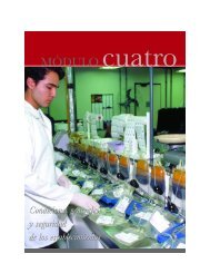
Mazagon plant(Spain)<br />
Capacity of 17 000 p.e (Photo Credits: F. Brissaud)<br />
Note: drained and buried vertical sand filters can be suitable for the<br />
smallest-sized plants (autonomous and grouped autonomous)<br />
which require a surface of 3,5 m 2 /p.e. instead of 1.5 m 2 /p.e. for<br />
open-air filtering.<br />
Determining the thickness<br />
When bacterial removal is not one of the objectives of the<br />
plant, a filter bed thickness of 80 cm is sufficient.<br />
In the case where infiltration-percolation has the elimination<br />
of pathogenic bacteria as an additional function, the<br />
thickness of the filter bed depends on the expected level<br />
of decontamination. The graph below provides the relationship<br />
between the reduction in faecal coliforms according<br />
to hydraulic load (h) and the thickness in the vertical<br />
sand filter (Etude Inter Agences n°9, 1993).<br />
If the bed is in natural sand, the relationship between its<br />
thickness and decontamination is more difficult to obtain, and it is preferable to call upon laboratories in order to<br />
properly characterise the sand in question and its bacterial<br />
removal capacities<br />
Reduction in faecal coliforms (u. log)<br />
The number of units is a function of:<br />
� the total surface area of the filter bed;<br />
� the maximum surface of the infiltration unit compatible<br />
with an even spreading of the effluent on the very unit.<br />
Implementation<br />
The walls of the ditches must be vertical if possible so<br />
that, at all points along the sand filter, the vertical path of<br />
the water is sand equal to the thickness of the bed.<br />
The height of the freeboard above the infiltration area<br />
must be around 30 cm. Safety overflow arrangements<br />
must be installed, in order to handle emergencies and dispose<br />
of the excess flow either into a receiving medium, or<br />
into other underloaded basins.<br />
The slopes forming the sides of the basins can be protected<br />
by concrete slabs, tarred sheet piles, air-placed<br />
concrete or even vegetation.<br />
EXTENSIVE WASTEWATER TREATMENT PROCESSES<br />
Feed<br />
Permeable soil in<br />
place<br />
Impermeable<br />
membrane<br />
Figure 8: Drained system with a draining bed<br />
made leak-proof via an impermeable membrane<br />
(Agences de l'Eau, 1993)<br />
H = 0.2 m/d<br />
H = 0.4 m/d<br />
H = 0.6 m/d<br />
Thickness of filter bed(m) H: hydraulic load<br />
Figure 9: Reduction in faecal coliforms according<br />
to hydraulic load (H in m/d) and thickness<br />
of the filter bed
Operation<br />
Table 6: Operation of an infiltration-percolation plant<br />
Tasks Observations<br />
Normal maintenance<br />
(every 3 to 4 days)<br />
Regular follow-ups<br />
Inspections every<br />
2 months<br />
Other maintenance<br />
operations<br />
* A vertical flow filter that is operated in an optimal manner produces nitrates and any decrease of concentration at its outlet (on a<br />
weekly or monthly scale) reflects a lack of oxygen therefore a degradation in the <strong>treatment</strong>.This follow-up can easily be carried out<br />
using test paper.<br />
Performances<br />
Excellent reduction results (in concentration) are obtained with this system:<br />
� BOD 5 less than 25mg/l;<br />
� COD less than 90mg/l;<br />
� SS less than 30mg/l;<br />
� Virtually complete nitrification;<br />
� Denitrification is limited with this type of installation. In its "autonomous purification" version, purification by the<br />
sail can allow a certain quantity of nitrogen to be eliminated. A study carried out within the Direction<br />
Départementale des Affaires Sanitaires and Sociales of Loire-Atlantique in 1993 demonstrated that it is possible<br />
to eliminate 40% of the nitrogen (sometimes even more) using a vertical flow sand filter.This reduction can reach<br />
50% if a horizontal flow sand filter is used (Cluzel F, 1993);<br />
� Phosphorus: high reduction during 3-4 years (60-70%), then less and then negative after 8-10 years (Duchemin J,<br />
1994);<br />
� Possibility of eliminating bacterial faecal contamination provided there is a sufficient material height and hydraulic<br />
operation without preferential flow (1000 times with 1 m of thickness).<br />
Technical advantages<br />
� excellent results on BOD 5 , COD, SS ;<br />
� high-level nitrification ;<br />
� surface area needed is much less than with natural lagooning ;<br />
� an interesting capacity for disinfection.<br />
Technical drawbacks<br />
� Valve operation;<br />
� cleaning of the grid;<br />
� observation of the degree of clogging of the surface of the infiltration units, and<br />
sometimes of the height of the water in the infiltration area;<br />
� drainage time for the <strong>wastewater</strong> doses;<br />
� in non-gravity plants, observation of pump flow;<br />
� keep a maintenance log that notes all the tasks carried out, flow measurements<br />
(flow meter canal, pump operating time), in order to obtain a good knowledge<br />
of the flows.This will also allow operating assessments to be produced.<br />
� inspection chamber, good water flow, aspect of the effluents;<br />
� removal of floating matter (settler-digester), sludge level (anaerobic lagoon or<br />
settler digester);<br />
� regulating level, maximum water height in the tank, feed devices (siphons,<br />
chutes, etc.);<br />
� valves or distributing devices;<br />
� Undermining and maintenance of levelling of the infiltration area;<br />
� plant output (drained systems) and quality of the discharges;<br />
� operation of sprinklers and cleaning (every month).<br />
� maintenance of electromechanical devices (1 to 2 times / year);<br />
� clearing of the earth banks around the bed;<br />
� organic accumulation that, at the end of the drying phases, are reduced to chips<br />
that can easily be detached from the sand must be raked and disposed of in a refuse<br />
collection point according to a periodicity that must be adjusted empirically;<br />
renewal of the first 5 to 10 cm of sand every 3-4 years should be scheduled;<br />
� empty the sludge from the settler-digester (once or twice / year) or settling<br />
lagoons (once or twice / year) or alternatively from the septic tanks (once / 3 to<br />
4 years);<br />
� regular analyses of the nitrogen content in the discharge which gives an indication<br />
of the good condition of the equipment *.<br />
� requires an effective primary settling tank;<br />
� the risk of clogging must be managed (hence the importance of the use of a "washed" sand with good sizing);<br />
� requires great quantities of sand to be available, which could lead to high capital cost if none is available nearby;<br />
� adaptation limited to hydraulic surcharges.<br />
EXTENSIVE WASTEWATER TREATMENT PROCESSES<br />
11
12<br />
▼ Vertical flow reed bed filters<br />
Operating principle<br />
The filters are excavations made to be impermeable, filled with successive layers of gravel or sand with a grading that<br />
varies according to the quality of the <strong>wastewater</strong> to be treated.<br />
As opposed to the previously mentioned infiltration-percolation, the raw influent is distributed directly, without<br />
prior settling, onto the surface of the filter. During flow through it is subject to a physical (filtering), chemical<br />
(adsorption, complexing, etc.) and biological (biomass attached to small media) <strong>treatment</strong>.The treated water is drained.The<br />
filters are fed with raw sewage by tanker-loads.Within the same plant, the filtering surface is separated into<br />
several units which makes it possible to establish periods of <strong>treatment</strong> and inactivity.<br />
The purifying principle lies in the development of an aerobic biomass attached to a reconstituted soil (see: chapter<br />
on stationary cultures on a thin support). Oxygen is supplied by convection and diffusion.The oxygen yield by the<br />
plant roots and rhizomes is, here, negligible in relation to the needs (Armstrong; 1979).<br />
VERTICAL REED BED FILTER: INTERMITTENT FEED<br />
WITH SURFACE AERATION<br />
untreated<br />
<strong>wastewater</strong> feed fine gravel<br />
coarse gravel<br />
ventilation<br />
pipe<br />
drainage<br />
pipe<br />
Figure 10: principle of vertical flow reed bed filters (source: CEMAGREF)<br />
Basis for design<br />
EXTENSIVE WASTEWATER TREATMENT PROCESSES<br />
pebbles<br />
treated effluent<br />
outlet<br />
The design of the vertical filters was established empirically by defining the acceptable daily limits for organic surface<br />
loads (20 to 25 g BOD5 m-2 .d -1 of the total cultivated surface).<br />
The first stage is designed to receive about 40 g BOD5 m-2 .d-1 thus representing 60 % of the total surface, or about<br />
1.2 m2/p.e. When the sewer network is combined or partially-combined , the design of the first stage is increased<br />
to 1.5 m2/p.e. (Agence de l'eau, 1999).This stage is divided into a number of filters which are multiples of 3, which<br />
allows rest periods for 2/3 of the time.<br />
The surface of the second stage is generally 40 % of the total surface area or about 0.8 m2 /p.e. At this stage, the<br />
necessary rest period is equal to that of operation, thus requiring the setting up of a number of filters which are<br />
multiples of 2 and equal to 2/3 of the number of filters used for the first stage (see diagram below).<br />
1 st stage 2 nd stage<br />
Implementation<br />
80 cm<br />
This approach is made<br />
up of:<br />
� A bar screen;<br />
� a first stage of vertical<br />
flow reed bed filters;<br />
� a second stage of<br />
vertical reed bed filters.<br />
Figure 11:<br />
Design diagram<br />
for the first and<br />
second stages<br />
Feed<br />
The flow of raw sewage(over the short dosing period) onto the 1st stage must be greater than the infiltration speed<br />
in order to correctly distribute the sewage over the whole bed surface.The deposits that accumulate on the surface<br />
contribute to reduce the intrinsic permeability (see glossary) of the media and thus improve the distribution of<br />
the sewage. Plants limit surface clogging, since the stems pierce the accumulated deposits. Water is distributed at<br />
several points.<br />
Media<br />
The media for the first stage is made up of several layers of gravel.The active layer is gravel that has a grading of 2 – 8<br />
mm, with a thickness of about 40 cm.The lower layers are of intermediate grading (10-20 mm) a 20 – 40 mm draining<br />
layer of gravel.<br />
The second stage refines the <strong>treatment</strong>.The risk of clogging is less. It is made up of a layer of sand (see infiltration-percolation)<br />
of a thickness of at least 30 cm.<br />
Drainage<br />
The 20 – 40 mm lower layer of gravel ensures draining of the effluent. Drains made out of plastic pipes, which are<br />
rigid and equipped with wide slits, are preferably used since they are less sensitive to clogging. Each drain is connected<br />
to an aeration pipe.
Planting<br />
Theoretically, several plant species can be used (Scirpus spp,Typha...), but reeds (of the Phragmites australis type),<br />
because of their resistance to the conditions encountered (long submerged period for the filter, dry periods, high<br />
rate of organic matter), and the rapid growth of the tangle of roots and rhizomes, are the most often used in temperate<br />
climates (Brix, 1987).The planting density is 4 plants/m 2 .<br />
Design<br />
Choice of land<br />
The constraints for the site are as follows:<br />
� Land availability: The surface area involved for this <strong>process</strong> sometimes makes it impossible to set up these systems<br />
in average-sized agglomerations where land is at a premium.<br />
� Slope: A difference in level of about 3 to 4 meters between the upstream and downstream points makes it possible<br />
to feed the filters by gravity ( using siphons that do not require any type of energy supply). For communities<br />
that are sized near 3,000 / 4,000 p.e., the use of pumps may become necessary.<br />
Operation<br />
Maintaining these systems does not have any particular requirements, but it needs regular and frequent checks by<br />
the operator.<br />
Table 7: Operation of vertical flow filters<br />
Tasks Frequency Observations<br />
Weeding the 1 st year � Manual weeding of self-propagating plants (Kadlec et al,2000). Once<br />
predominance is established, this operation is no longer necessary.<br />
Cutting 1 / year<br />
(autumn)<br />
Regular<br />
maintenance and<br />
follow-up<br />
Regular<br />
maintenance<br />
Other maintenance<br />
operations<br />
* A vertical flow reed bed filter operating in an optimal manner produces nitrates and any lowering of the concentration at its outlet<br />
(on a weekly or monthly scale) reflects a lack of oxygen, therefore a lowering of the standard in the <strong>treatment</strong>.This follow-up can easily<br />
be carried out using test paper.<br />
Performance<br />
1 / quarter<br />
1 / week<br />
� BOD 5 : ≤ 25 mg/l<br />
� COD: ≤ 90 mg/l<br />
� SS: ≤ 30 mg/l<br />
� KjN: ≤ 10 mg/l in general with peaks that do not exceed 20 mg/l<br />
� Phosphorus: Reduction is normally low (depends on the adsorption capacity of the substrate and on the age of<br />
the plant)<br />
� Pathogenic bacteria: (reduced by 10 to 100 fold).<br />
Technical advantages<br />
� Easy to operate and low operating cost. No energy consumption if the topography makes this possible;<br />
� Possibility of treating raw domestic sewage;<br />
� Sludge management is reduced to a minimum;<br />
� Adapts well to seasonal variations in population(eg. Holiday sites, camping<br />
and caravan sites, remote hotels).<br />
Technical drawbacks<br />
� Regular operation, annual cutting of the exposed portion of the reeds,<br />
manual weeding before predominance of reeds;<br />
� Using this approach for capacities greater than 2,000 p.e. remains<br />
marginal for reasons of controlling costs and hydraulics compared<br />
with traditional approaches. A design for larger sizes can only be<br />
considered after serious considerations over the adaptation of the<br />
basis of design and the conditions to be fulfilled in order to ensure<br />
control of hydraulics;<br />
� Risk of presence of insects or rodents.<br />
� Cutting down and disposal of reeds. Disposing of them stops them<br />
accumulating on the surface of the filters. With a view to reducing this<br />
maintenance time, reeds can sometimes be burned if the waterproofing<br />
does not use a geomembrane, and if the feed pipes are made of<br />
cast iron (Liénard et al, 1994).<br />
� Clean the feeding siphon at the first stage by pressure washing.<br />
� Periodic analyses of nitrates in the effluent will indicate the health of<br />
the plants*.<br />
1 to 2/ week � Clean the bar screen.<br />
1 / week<br />
� Regularly check the correct operation of the electromagnetic devices<br />
and detect breakdowns as quickly as possible.<br />
2 / week � Changing the valves<br />
Each visit � Keep a maintenance log noting all the tasks carried out, flow measurements<br />
(flow meter canal, operating time of the pumps), to obtain good<br />
understanding of the flow.This also allows operating assessments to be<br />
produced.<br />
Oakland parks plant (United Kingdam)<br />
Capacity 65 P.E (Photo credits Paul Cooper)<br />
EXTENSIVE WASTEWATER TREATMENT PROCESSES<br />
13
14<br />
▼ Horizontal flow reed bed filters<br />
Operating principle<br />
In horizontal flow reed bed filters, the filter pack is almost totally saturated with water.The effluent is spread out<br />
over the entire inlet horizontal cross-section of the bed by a distributor system located at one end of the bed; it<br />
then flows in a direction that is practically horizontal through substrate. Most of the time, feeding takes place continuously<br />
since the supplied organic load is low.<br />
Removal takes place via a drain positioned at the opposite end of the bed, at the bottom and buried in a trench of<br />
draining stones.This pipe is connected to a siphon which allows the height of the overflow to be adjusted, and thus<br />
the level of the water in the bed, in such a way that it is saturated during the feeding period.The water level must<br />
be maintained at approximately 5 cm under the surface of the material. In fact, water must not circulate above the<br />
surface, so as to avoid short-circuiting of <strong>treatment</strong>; therefore there is no free water surface and no risk of insect<br />
proliferation.<br />
Design<br />
To define the necessary surface area, the empirical values below provide the expected purification results (Vymazal<br />
et al, 1998):<br />
� For initial concentrations of around 150 to 300 mg.l-1 of BOD5 , the planted surfaces are around 5 m2 /p.e. in<br />
secondary <strong>treatment</strong>, which corresponds to kBOD5 = 0.1m/d;<br />
� For concentrations between 300 and 600 mg.l-1 of BOD5, concentrations which better represent those<br />
of current urban <strong>wastewater</strong> it seems preferable to opt for the Danish method which consists in dimensioning<br />
the filter at 10 m2 /p.e.;<br />
� For treating effluents from storm sewage overflows (Cooper,1996) the surface needed is 0.5 m2 /p.e.<br />
The filter section must be defined by a technical expert. It is a function of the initial permeability of the chosen<br />
material (1 to 3.10-3 m .s-1 ).<br />
The depth of the filter will be equal to the maximum penetration depth of the roots. This depth is 60 cm for<br />
Phragmites (Marsteiner, 1996).<br />
The hypothesis of a notable improvement in initial hydraulic conductivity, following intense root development of<br />
the reeds, in density as well as in depth, has not been confirmed (Boon, 1986). In fact, the increase in hydraulic<br />
conductivity thanks to root development is partially compensated by the accumulation of SS and of organic matter<br />
(Cooper, 1996). It is<br />
Untreated<br />
<strong>wastewater</strong> feed<br />
influent gabion<br />
distributor<br />
Figure 12: side view of a horizontal flow reed bed bed (Source: Cooper, 1993)<br />
Implementation<br />
EXTENSIVE WASTEWATER TREATMENT PROCESSES<br />
HORIZONTAL FLOW REED BED FILTER: CONTINUOUS FLOW<br />
coarse sand or<br />
fine gravel<br />
Water level<br />
water outflow<br />
gabion<br />
treated water<br />
outlet<br />
60 cm<br />
therefore important that<br />
the chosen support has<br />
a permeability of 1 to<br />
3.10 -3 m.s-1. Most soils<br />
must therefore be excluded<br />
and gravel used instead.<br />
Partitioning<br />
For designs greater than 500 m 2 ,a partitioning into several units of reduced size will facilitate maintenance and<br />
improve hydraulic separation.<br />
Slope<br />
The bed surface is flat.The slope at the bottom of the bed must allow the filter to be completely emptied.The bottom<br />
slope must not however provoke the drying out of the roots at the output level.A variation in the bed depth<br />
equal to 10 % of the height of the material at the input area is enough (Kadlec, R.H. et al,2000).<br />
Materials<br />
At the outset, the <strong>process</strong> was developed using the existing soil, while endeavouring to attain, in the long run, a<br />
hydraulic conductivity of 3.10 -3 m s -1 .A large number of filters were built according to hypothesis that hydraulic<br />
conductivity would increase with root development.<br />
Following some bad experiences, it is now recommended to use washed gravel, with different degrees of grading according to<br />
the quality of the incoming water (3-6, 5-10, 6-12 mm) (Vymazal , 1998).<br />
Plants<br />
The most widely used variety is the Phragmites australis reed because of its rapid growth, its root development and<br />
its resistance to soil saturation conditions. Planting can take place using seeds, young shoots or rhizomes with a density<br />
of about 4 per m2 .
Design<br />
Choice of land<br />
The constraints concerning the site are as follows:<br />
� Large land space needed;<br />
� Topography: A difference in level of a 1 meter between the feeding point of the plant and downstream point<br />
makes it possible to feed the filters by gravity.The required difference in level is not very much because of the<br />
horizontal flow.<br />
� Soil characteristics at the bottom of the filter: if the soil is clay-like, natural waterproofing can be reached by<br />
simple compaction (required conductivity of 1.10-8m.s-1). Failing this, the installation of a waterproof geomembrane<br />
is necessary.<br />
Operation<br />
Maintaining these systems does not have any particular requirements, but needs the operator to come and inspect<br />
the equipment regularly and frequently. For the population range that we are interested in, one must nevertheless<br />
think about the maintenance of primary settlement structures (removal of sludge) and of the biological <strong>treatment</strong><br />
stage in the case where the reed bed filter is for tertiary <strong>treatment</strong>.<br />
Tableau n°8 : Exploitation des filtres plantés à écoulement horizontal<br />
Tasks Frequency Observations<br />
Maintenance of<br />
pre-<strong>treatment</strong><br />
structures<br />
Adjustment of<br />
output level<br />
Vegetation<br />
Weeding<br />
Cutting<br />
Other maintenance<br />
operations<br />
Performance<br />
1 / week The aim is to ensure their proper operation and that they do not<br />
discharge too many SS which could cause clogging.<br />
1 / week Regular adjusting of the output water level makes it possible to avoid<br />
surface runoff. For large plants (> 500 m3d-1), verifying the output<br />
level could require daily inspection.<br />
The hydraulic aspect with this type of <strong>process</strong> is a key item.<br />
The correct distribution of the effluent in the filter should be<br />
checked. Cleaning the feed distribution device should be incorporated<br />
into the design.<br />
1st year<br />
During the first year (and even during the second) it is preferable to<br />
weed the self-propagating plants manually so as not to hinder reed development<br />
(Kadlec R.H. et al, 2000).This operation can also be carried out<br />
by slightly immersing the surface of the filter (10 cm) to the detriment<br />
of purification output (Cooper, 1996). Once predominance of reeds is<br />
established, this operation is no longer necessary.<br />
not necessary<br />
The absence of surface runoff makes it possible to avoid cutting.<br />
Dead plants do not hinder in any way the hydraulics of the filters and<br />
furthermore allow the filter to be thermally insulated.<br />
Each visit Keep a maintenance log with all the tasks that are carried out and<br />
the flow measurements (flow meter canal, pump operating time),<br />
so as to obtain good understanding of the flows.This also allows<br />
operating assessments to be produced.<br />
In terms of performance for BOD5 ,for incoming concentrations varying from 50 to 200 mg/l, and for a sizing of 3 to<br />
5 m2 /p.e., flow systems of the horizontal type and lined with gravel result in reductions of about 70 to 90 %.These<br />
concentrations are however too low to be considered as representative of urban waste water and it seems more<br />
prudent to follow the Danish example.<br />
In fact, 80 Danish sites, sized at about 10 m2 /p.e., achieve removals of approximately 86 % for BOD5 and SS, 37 %<br />
for total nitrogen, and 27 % on for total phosphorus (Cooper, 1996).<br />
Generally speaking, in secondary <strong>treatment</strong>, nitrification is limited but denitrification is very good.<br />
The removal of phosphorus depends of the type of soil used, but remains relatively low.<br />
Technical advantages<br />
� Low energy consumption;<br />
� No highly-qualified personnel needed for maintenance;<br />
� Does not need significant slope for gravity feeding (< 1 m);<br />
� Reacts well to variations in load.<br />
Technical drawbacks<br />
� A lot of ground area is needed (as for natural lagoons);<br />
� A plant for sizes of about 4,000 p.e. can only be considered if serious thought is given to the design parameters<br />
in particular the controlling hydraulics.<br />
EXTENSIVE WASTEWATER TREATMENT PROCESSES<br />
15
16<br />
�Suspended growth cultures<br />
▲ Operation: design principles<br />
The purification <strong>process</strong> using "suspended growth cultures" relies on the development of bacterial cultures, mainly<br />
of the aerobic type. Oxygen comes from many sources depending on to the approaches taken.<br />
The bacterial culture is separated from the treated water by a sedimentation structure, most often, specifically clarifier,<br />
settling lagoon, etc..<br />
▲ Natural lagoons (stabilisation ponds)<br />
Operating principle<br />
Purification is ensured thanks to a long retention time, in several watertight basins placed in series.The number of<br />
basins most commonly used is 3. However, using a configuration with 4 or even 6 basins makes more thorough disinfection<br />
possible.<br />
The basic mechanism on which natural lagooning relies is photosynthesis.The upper water segment in the basins is<br />
exposed to light.This allows the development of algae which produce the oxygen that is required for the development<br />
and maintainance of aerobic bacteria.These bacteria are responsible for the decomposition of the organic matter.<br />
Carbon dioxide produced by the bacteria, as well as mineral salts contained in the waste water, allows the planktonic<br />
algae to multiply.Therefore, there is a proliferation of two interdependent populations: bacteria and algae, also<br />
called "microphytes".This cycle is self-maintained as long as the system receives solar energy and organic matter.<br />
At the bottom of the basin, where light does not penetrate, there are anaerobic bacteria which break down the sludge<br />
produced from the settling of organic matter. Carbon dioxide and methane are released from this level.<br />
Input<br />
Basis for design<br />
Wind<br />
atmospheric O 2<br />
Natural lagooning is made up of, most often, of several watertight basins or "microphyte lagoons", operating in<br />
series.<br />
Number of lagoons<br />
A plant with three lagoons is common and makes it possible to ensure a good level of operating reliability for the<br />
removal of organic matter.The highest possible performance levels, as far as disinfection is concerned, are only reached<br />
with larger-sized partitioning (up to six lagoons in series).<br />
The respective roles of each of the different basins is as follows:<br />
� the first allows, above all, a reduction in the polluting load that contains carbon;<br />
� the second allows nitrogen and phosphorus to be reduced;<br />
� the third refines the <strong>treatment</strong> and makes the system reliable, in case an upstream basin malfunctions, or during<br />
maintenance work.<br />
The daily surface load applied is approximately 4.5 g BOD 5 per m 2 of total surface area, which corresponds to a<br />
water body surface area of approximately 10 to 15 m 2 / p.e. (Vuillot et al, 1987).<br />
EXTENSIVE WASTEWATER TREATMENT PROCESSES<br />
O 2<br />
O 2<br />
Soluble organic<br />
biodegradable matter<br />
CO2 O2 Protozoic<br />
aerobic<br />
Soluble and insoluble organic and<br />
inorganic settleable matter<br />
bacteria<br />
Anaerobic zone<br />
Bottom<br />
Light<br />
Solar radiation<br />
CH4 CO2 NH3 Optional anaerobic<br />
bacteria<br />
Surface<br />
Treated water<br />
+ Algae<br />
Phosphates<br />
and nitrates<br />
Discharge<br />
Figure 13: Mechanisms found in natural lagoon basins (according to<br />
Agences Financières de Bassin, CTGREF, 1979)<br />
1 m
The low load applied results in a long residence time in the basins. In the absence of rainwater, the retention time<br />
is around 70 days. In hot and dry climates (countries in the south of Europe), the design surface area can be halved,<br />
thanks to the temperature which accelerates the biological <strong>process</strong>es and thanks to evaporation which increases<br />
retention time (see Radoux M., Cadelli D., Nemcova M., Ennabili A., Ezzahri J.,Ater M., 2000).<br />
For this reason, the volumes to be treated are, at any given instant, completely different from the volumes discharged<br />
into the natural environment. So as to ensure proper hydraulic operation of the structures (and to detect possible<br />
infiltration from the water table or, inversely, leaks), it is thus important to always be able to compare the upstream<br />
and downstream flows by using appropriate devices (flow meters or pump operating times).<br />
Design of the first lagoon<br />
The value of 6m2 / p.e. is successfully used, which corresponds to a nominal surface load of around 8.3 g BOD5 /m2 per day.<br />
For plants with a variable population, and in hot and sunny weather, design can be carried out on the basis of the<br />
maximum monthly peak flow.<br />
The shape of the lagoon must not favour bacterial growth at the expense of algae. The balance between the two<br />
must be respected so that the oxygen yield remains sufficient.To do this, the best shape of the basin is deeper rather<br />
than long and narrow.A length to width (L/l) < 3 ratio is used in France (see the following diagram).<br />
The depth of the basin must make it possible:<br />
� to avoid the growth of higher forms of plant life;<br />
� to obtain maximum penetration of light and oxygenation to the water volume;<br />
The depth of the water in the lagoon must therefore be 1 meter (± 0.2 m). However, in order to facilitate cleaning<br />
the sludge deposits that normally develop around the feed point, a settlement zone that is deeper can be built.This<br />
zone, that has an additional depth of 1 meter maximum, covers a few dozen m 2 . It must always be accessible from<br />
the sides or from an access ramp built for this purpose.<br />
Design of the second and third lagoons<br />
These two basins must be of similar dimensions and the total surface area of the two bodies of water must be equal<br />
to 5 m2 / p.e.<br />
The depth of the water must be 1 meter (± 0.2 m).The overall shape can vary to a certain extent, in accordance<br />
with particular topographical constraints and the planning permission required to obtain proper integration into the<br />
landscape.<br />
Pre-<strong>treatment</strong> of raw sewage<br />
A bar screen must be installed before <strong>treatment</strong> on large plants. For plants with less than 500 p.e. it is possible to<br />
use a mobile floating suction barrier.At the entrance to the first basin, a suction barrier (fat/oil collector) that is submerged<br />
30 to 40 cm makes it possible to retain floating solids.<br />
Space needed<br />
The choice of land depends upon the size of the space that the lagoon system takes up on the ground.The surface area<br />
of the lagoons includes the bodies of water as well as the approaches which must be designed to facilitate maintenance.<br />
For example, approximately 15 m 2 /p.e. of total surface area is needed to construct the 4,400 m 2 of basins required to<br />
treat the waste water generated by 400 p.e. 0.6 hectare is therefore necessary (see the drawing below).<br />
I L<br />
6 m 2 per equivalent<br />
inhabitant<br />
Water circulation<br />
2.5 m 2 per<br />
equivalent<br />
inhabitant<br />
2.5 m 2 per<br />
equivalent<br />
inhabitant<br />
Figure 14: Ground space taken up by natural lagoons<br />
(Agence de l’eau Seine-Normandie, CEMAGREF – 1998)<br />
Location<br />
The structure should generally be located at<br />
a lowest point, at a position where prevailing<br />
winds contribute to aerating the watersurface.<br />
But, if more watertight (silt/clay) soils<br />
are available at higher positions pumping can<br />
be considered.<br />
There must not be any trees closer than<br />
10 metres, since their roots could create<br />
preferential paths through the dikes.<br />
Furthermore, their leaves could fall into the<br />
basins and cause an organic overload as well<br />
as a risk of obstructing connecting structures.<br />
The land must be of the clay-silt type. The<br />
substratum must absolutely not be karstic<br />
or fractured.<br />
Topography<br />
The land must be chosen in such a way that gravity helps the flow down to the receiving area. A spot that would<br />
cause a minimum of construction work should be sought out. Finally, land that is too steep must not be used because<br />
of the risks of collapsing, erosion and pur off from the catchment areas (a catchment area with too steep a slope<br />
would cause a very strong and sudden increase in the flow of rainwater after a storm).<br />
EXTENSIVE WASTEWATER TREATMENT PROCESSES<br />
17
18<br />
Implementation<br />
Banking up work<br />
The slope of the naturally watertight dikes must have an H/ L relationship of at least 1/2.5 so as to:<br />
� limit the erosive action caused by lapping;<br />
� facilitate regular maintenance;<br />
� allow access to all the basins for the cleaning equipment.<br />
In order to protect against erosion caused by lapping and possible damage caused by rodents, it is useful to turf the<br />
bank sides before adding water or to use self-locking slabs or blocks, geogrids , geotextiles or any other material to<br />
protect the sides.<br />
Dikes must be built up by successive compactions of 15 to 20 cm layers, so as to ensure homogenous settling all the<br />
way to the "heart of the embankment" .<br />
Compacting the invert must be carried out after that of the dikes.<br />
Installing a watertight geomembrane is possible but has the disadvantage of increasing the investment capital cost of<br />
the structure. In this situation, the slope of the dikes can be greater (up to 1/1.5), the total surface area taken up by<br />
the structures will therefore be less.<br />
Siphon pipe arrangements must be provided between basins so as to stop the transmission of hydrocarbons and<br />
duckweed.<br />
It is preferable to install a stationary by-pass on each basin in order to facilitate the operations of emptying and cleaning.<br />
The last step in the construction is to quickly fill with clean water the different basins so as to establish<br />
the permeability, while avoiding any risk of drying out of the structure, verify watertightness and<br />
to help setting up of the ecosystem (including vegetation of the banks).<br />
Smells could appear with the change of seasons (linked to the phenomenon of anaerobiosis) if the effluent present<br />
in the first lagoon is too concentrated. It is possible to solve this situation by recirculating the water in the first basin<br />
or by diluting the effluent using a flush system in the network.<br />
In order to avoid seepage into and between the lagoons, it is absolutely necessary that a hydrogeological and pedological<br />
study is done beforehand.<br />
Operation<br />
The table below provides a more detailed description of the tasks to be carried out.<br />
Table 9: Operating lagoons<br />
Task Frequency Observations<br />
General monitoring – check list:<br />
� presence of rodents;<br />
� obstruction of connecting<br />
structures;<br />
� development of duckweed;<br />
� proper water flow;<br />
� absence of floating debris;<br />
� water colour;<br />
� absence of odours;<br />
� state of the dikes/ banks.<br />
Maintenance of pre-<strong>treatment</strong><br />
structures<br />
Cuttting on the dikes and on<br />
the sides and on the plant belt<br />
(or grazing by sheep)<br />
Partial cleaning of the sedimentation<br />
cone (at the entrance of<br />
the first basin)<br />
Cleaning of the basins Every 5 to 10 years,<br />
according to<br />
the load actually<br />
received for the<br />
first basin, every<br />
20 years for the<br />
following basins<br />
EXTENSIVE WASTEWATER TREATMENT PROCESSES<br />
1 / week This verification must be done by walking around all of<br />
the dikes. This method has the advantage of dissuading<br />
the settling in of rodents.<br />
Furthermore, methods for the fight against duckweed<br />
are either prevented by the settling in of ducks, or curative<br />
by the removal of plants (by floating plank for<br />
example).<br />
1 / week It involves preventing build up of effluents in the network<br />
or by-pass and avoiding bad odours;<br />
2 to 4 / year The idea is to maintain access to the bodies of water, to<br />
limit the settling in of rodents and the development of<br />
insect larva and to check the state of the sides.<br />
1 to 2 / year Must be done with liquid pumping.<br />
Must be implemented when the volume of sludge reaches<br />
30% of the volume of the basin.<br />
Two methods of cleaning are normally used:<br />
� by an earthmoving machine, once the basin has been<br />
emptied.This implies the presence of a stationary<br />
by-pass on each basin;<br />
� by pumping, without prior emptying, called "emptying<br />
under water".
Performance<br />
The results, calculated on the flow of organic matter, achieves more than 75 % , which corresponds to a filtered COD<br />
concentration of 125 mg/l. Furthermore, the flow, and therefore the discharged flow, is often reduced in summer<br />
(-50%) by evapotranspiration.<br />
The concentrations in total nitrogen at the discharge level are very low in the summer, but can reach several dozen<br />
mg/l (expressed in N) in the winter.<br />
The reduction in phosphorus is noticeable over the first few years (> 60%), then dwindles down to zero after about<br />
20 years.This drop is due to a release of phosphorus from the sediment.The initial conditions will be restored by<br />
cleaning the basins (when the area is sensitive to phosphorus, cleaning must take place every 10 years, not every 20<br />
years).<br />
Disinfection is important, especially in the summer (microbial reduction > 10,000).This performance is linked to the<br />
long retention time of the effluent (around 70 days for a complete <strong>treatment</strong>) with U.V. radiation effects and biological<br />
competition.<br />
Advantages<br />
� A supply of energy is not necessary if the difference in level is favourable;<br />
� Operation remains simple, but if overall cleaning does not take place in time, the performance of the lagoon is<br />
severely reduced;<br />
� Eliminates a large portion of the nutrients: phosphorus and nitrogen (in summer);<br />
� Very good elimination of pathogenic organisms in the summer (4-5 logs), good elimination in winter (3 logs);<br />
� Adapts well to large variations in hydraulic load;<br />
� No "hard permanent" constructions, civil engineering remains simple;<br />
� Integrates well into the landscape;<br />
� Absence of noise pollution;<br />
� Pedagogic equipment for nature initiation;<br />
� Sludge from cleaning is well stabilised (except that from at the head of the first basin) and is easy to spread on<br />
agricultural land.<br />
Technical drawbacks<br />
� Much ground space needed;<br />
� Capital costs depend very heavily depending on the type of substratum.With unstable or sandy land, it is preferable<br />
not to consider this type of lagoon;<br />
� Performance is less than in intensive <strong>process</strong>es with respect to organic matter. However, the discharge of organic<br />
matter takes place in the form of algae, which has less adverse effects than dissolved organic matter for oxygenation<br />
of the zone downstream. Moreover this discharge remains low in the summer (as a result of evapotranspiration),<br />
which is the most unfavourable period for watercourses and so the reduction of fluxes discharged<br />
is a benefit at this period;<br />
� Quality of discharge varies according to season.<br />
▲ Macrophyte lagoons<br />
Macrophyte lagoons reproduce natural wetlands with a free water surface, while trying to highlight the interests<br />
of natural ecosystems.They are rarely used in Europe, but are often carried out for tertiary <strong>treatment</strong> following<br />
natural lagooning, optional lagoons or aerated lagooning in the United States.This approach is generally used with<br />
the purpose of improving <strong>treatment</strong> (on the BOD 5 or SS parameters) or to refine it (nutrients, metals, etc.).<br />
However the use of a microphyte finishing lagoon can show better results and is easier to maintain.<br />
EXTENSIVE WASTEWATER TREATMENT PROCESSES<br />
19
20<br />
▲ Aerated lagoons<br />
Operating principle<br />
General description<br />
Oxygenation is, in the case of aerated lagoons, supplied mechanically by a surface aerator or air blower. This<br />
principle differs from activated sludge only by the absence of continuous sludge extraction or sludge recycling<br />
systems. Energy consumption for the two approaches is, with equivalent capacities, comparable (1.8 to 2 kW/kg<br />
BOD 5 eliminated).<br />
Major mechanisms that come into play<br />
In the aeration stage, the water to be treated is in contact with micro-organisms that consume and assimilate the<br />
nutrients produced by the pollution that is to be removed .These micro-organisms are essentially bacteria and fungi<br />
(comparable to those present in activated sludge plants).<br />
In the settling stage, suspended solids which are clusters of micro-organisms and trapped particles, settle to form<br />
sludge.This sludge is regularly pumped or removed from the basin when their volume becomes too great.This settling<br />
stage is made up of a simple settling lagoon, or preferably, two basins which can be by-passed separately for cleaning<br />
operations.<br />
With aerated lagoons, bacterial population without recirculation leads to:<br />
� a low density of bacteria and a long <strong>treatment</strong> time in order to obtain the required quality;<br />
� reduced of bacteria flocculation, which requires the installation of a suitably sized settling lagoon.<br />
Input Discharge<br />
Basis for design<br />
3 m 3 per p.e.<br />
served<br />
EXTENSIVE WASTEWATER TREATMENT PROCESSES<br />
Watercourse<br />
0.3 to 0.5 m 3<br />
per p.e.<br />
0.3 to 0.5 mfl<br />
per p.e.<br />
Choice of land<br />
A surface area between 1.5 to 3 m 2 per p.e. must be planned for.<br />
Aeration lagoon<br />
Table 10: Design basis for aerated lagoons<br />
Parameter Design basis<br />
Figure 15: Drawing of the principle<br />
of aerated lagoons<br />
(according to Agences Financières<br />
de bassin, CTGREF – 1979)<br />
Retention time 20 days (retention times are reduced, in fact, to about two weeks after a few years of<br />
operation following the volume occupied by the deposit of suspended solids one must<br />
therefore not try to reduce this retention time during design).<br />
Volume 3 m3 per user served.<br />
Depth 2 to 3.50 m with surface aerator (fast 4 kW turbines correspond to depths of about<br />
2.5 m, those at 5.5 kW are used with depths between 2.5 and 3 m)<br />
> 4.00 m possible with air blower.<br />
Shape of the basin a square around each aerator.<br />
Specific aeration<br />
power<br />
Oxygen needs are around 2 Kg O 2 / kg BOD 5 . In order to reduce deposits to a volume<br />
that does not affect the <strong>treatment</strong> and, furthermore, to prevent the formation of microscopic<br />
algae, it is necessary to oversize the aerators and to use a power level between<br />
5 and 6 W / m 3 . During operation, it is always possible to reduce the operating time of<br />
these reactors in relation to the operating time of the less powerful fans, which makes it<br />
possible to limit operating surcharges.
Settling lagoon<br />
Table 11: Design basis for settling lagoons<br />
Parameter Dimensions<br />
volume 0.6 to 1 m3 per p.e.<br />
Depth 2 to 3 m with surface fans.<br />
Shape of the basin<br />
Depth<br />
rectangular with a length / width relationship equal to 2/1 or 3/1.<br />
2 m so as to allow for one meter of water free before sludge extraction.<br />
The use of two settling lagoons with a retention time of 4 days (0.6 m3/p.e. x 2) and operating alternately facilitates<br />
sludge extraction, which must take place every two years.<br />
Implementation<br />
Contrary to natural lagoons, watertightness via a geomembrane will be selected so as to limit the risks of degradation<br />
of the sides by excessive lapping of water. In the case of natural watertightness , it is advisable to install material<br />
that provides protection against water lapping on the sides (air-placed concrete, geogrids + planting of rushes).<br />
The life of the structure is dependent on this.<br />
Whatever construction method is chosen, concrete slabs and blocks complement the protection against undermining<br />
at the level of the turbine.<br />
Operating<br />
The different tasks involved in operation and maintenance are listed in the following table:<br />
Table 12: Operation of aerated lagoons<br />
Task Frequency Observations<br />
Cleaning of<br />
pre-<strong>treatment</strong><br />
installations (grids +<br />
suction barrier)<br />
1 / week<br />
General inspection<br />
of the basins<br />
1 / week<br />
Extraction of sludge<br />
from the settling<br />
lagoons<br />
Once every<br />
two years in<br />
nominal load<br />
The 1st emptying is not necessary until after 3 or 4 years of<br />
operation.<br />
Adjustment and<br />
programming of<br />
aeration<br />
2 / year This is the most complex operation which requires, several weeks<br />
after each charge, a verification of the new biological balance in the<br />
basin.<br />
Cutting down and<br />
clearance of plants<br />
2 to 5 / year<br />
Verification and<br />
reading of the<br />
counters<br />
1 / week<br />
Maintain a log 1 / week<br />
Performance<br />
The level of quality of the effluent is good for organic matter: a reduction of more than 80%. For nutrients, elimination<br />
remains limited to bacterial assimilation and remains around 25-30%.<br />
This approach can easily be adapted for the addition of physico-chemical additives with a view to eliminating orthophosphates.<br />
Technical advantages<br />
This <strong>process</strong> is particularly tolerant of very many factors which cause, in general, very serious malfunctions in traditional<br />
purification <strong>process</strong>es:<br />
� large variation in hydraulic and/or organic loads;<br />
� highly concentrated discharges;<br />
� effluents with unbalanced nutrients (cause of bulking of activated sludge);<br />
� joint <strong>treatment</strong> of industrial and domestic biodegradable discharges;<br />
� integrates well into the landscape;<br />
� stabilised sludge;<br />
� removal of sludge only every two years.<br />
Technical drawbacks<br />
� discharge of average quality concerning all parameters;<br />
� presence of electromechanical equipment requiring maintenance by a specialised agent;<br />
� noise pollution linked with the presence of the aeration system;<br />
� high energy consumption.<br />
EXTENSIVE WASTEWATER TREATMENT PROCESSES<br />
21
22<br />
Combined systems [association of extensive approaches<br />
(fixed film and suspended growth cultures)]<br />
The association of several natural systems, in free or<br />
stationary cultures, in series or in parallel, is sometimes<br />
implemented in order to adapt the <strong>treatment</strong> to a specific<br />
goal (quality of the discharge, integration of rainwater,<br />
special influent, etc.).<br />
As a main <strong>treatment</strong>, very little experience is available,<br />
and actual performance levels are difficult to evaluate.<br />
Certain studies (Radoux M. et al , 2000) on MHEA‚<br />
(Hierarchical Mosaics of Artificial Ecosystems) show<br />
some interesting potential without defining written<br />
bases for sizing.<br />
The use of vertical and horizontal reed bed filters in<br />
series seems to be an interesting solution in order to<br />
allow a more thorough <strong>treatment</strong> of nitrogen and phosphorus<br />
according to the type of support used (Cooper,<br />
1999).A first stage of vertical flow filters allows a good<br />
reduction in SS, in BOD5 as well as almost total nitrification.<br />
A second stage of horizontal flow reed bed filters<br />
improves the <strong>treatment</strong> on SS and BOD5, and<br />
makes possible denitrification as well as adsorption of<br />
phosphorus if the chosen support has good characteristics<br />
(Fe,Al, Ca).<br />
More complex configurations are often used to refine<br />
secondary or tertiary <strong>treatment</strong>s. After <strong>treatment</strong> of<br />
the aerated lagoon or natural lagoon types, emergent<br />
macrophyte lagoons can eliminate the risk of temporary<br />
discharges of mediocre quality.<br />
EXTENSIVE WASTEWATER TREATMENT PROCESSES<br />
Optional lagoon systems followed by emergent macrophyte<br />
lagoons are often used for the <strong>treatment</strong> of rainwater<br />
(Strecker et al ,1992).<br />
When the population range reaches a value that is close<br />
to 4,000 p.e., it is useful to closely compare the capital<br />
and operational costs with <strong>process</strong>es that are more<br />
intensive.The management constraints due to the large<br />
surface area should not be ignored.<br />
A multitude of configurations are possible according to<br />
the needs to reproduce the various natural wetland systems.<br />
One must nevertheless take into consideration<br />
the fact that the increase in the complexity of a <strong>treatment</strong><br />
plant of this type takes place to the detriment of<br />
simplicity in management, which is however very much<br />
sought after. Furthermore, the current state of scientific<br />
knowledge on the operation of wetlands pressures<br />
us most often to try to simplify the configuration so as<br />
to better control purification.
CONCLUSIONS: ELEMENTS<br />
FOR THE TECHNICAL CHOICES<br />
Summary of the different approaches �<br />
Purifying techniques that correspond to the terminology of the "extensive approaches" are briefly summarised in the<br />
table below, which shows that for some of them, primary <strong>treatment</strong> is needed (see glossary) upstream, and for<br />
others, they should be used exclusively as a finishing (or tertiary) <strong>treatment</strong>.<br />
Table 13: <strong>Extensive</strong> purifying techniques<br />
Traditional approach Primary <strong>treatment</strong> Secondary <strong>treatment</strong> Tertiary <strong>treatment</strong><br />
Infiltration –percolation Settler digester Infiltration - percolation<br />
Vertical flow reed bed<br />
filters<br />
Horizontal flow reed bed<br />
filters<br />
Settler / digester Horizontal flow filters<br />
Natural lagoons 1st lagoon basin 2nd lagoon basin 3rd lagoon basin<br />
Macrophyte lagoons Not recommended Not recommended One or more basins<br />
Aerated lagoons Aerated lagoon + settling lagoon Finishing lagoon<br />
Hybrid system,<br />
for example…<br />
Most of them ensure a positive elimination of one of the parameters that characterises tertiary <strong>treatment</strong> (nitrogen,<br />
phosphorus or bacteria that indicate faecal contamination).The levels may be variable and are shown in Table 14.<br />
The effectiveness of extensive approaches according to parameters is shown below:<br />
Table 14: Effectiveness of extensive approaches according to parameters<br />
Quality of discharges �<br />
Parameters OM*=<br />
Organic<br />
matter<br />
KjN* Total N* Total P* Microbial removal<br />
Infiltration - percolation Yes Yes No No If special design made<br />
Vertical flow reed bed<br />
filters<br />
Horizontal flow reed bed<br />
filters<br />
1st lagooning basin, 2nd lagooning basin Infiltration - percolation<br />
Aerated lagoon + settling lagoon Infiltration - percolation<br />
Vertical flow reed bed filters +Horizontal flow reed bed filters<br />
Yes Yes No No<br />
Yes Poor<br />
nitrification<br />
Good denitrification<br />
Natural lagoons Average Yes Yes Yes,<br />
the first<br />
years<br />
Yes<br />
Macrophyte lagoons Average Yes Yes Yes,<br />
the first<br />
years<br />
Yes<br />
Aerated lagoons Average Average No No No<br />
* see glossary<br />
Absolutely essential<br />
(Vertical flow filters can be<br />
used for this primary <strong>treatment</strong>)<br />
Vertical flow filters<br />
(1 st stage)<br />
No<br />
Vertical filters<br />
(2 nd stage)<br />
No<br />
No<br />
EXTENSIVE WASTEWATER TREATMENT PROCESSES<br />
23
24<br />
�Advantages and drawbacks: summary<br />
The choice is therefore going to be made according to the advantages and disadvantages of the different techniques<br />
that are summarised in the table below.<br />
Table 15: Summary of advantages and drawbacks of extensive approaches<br />
Approach Advantages Drawbacks<br />
Infiltrationpercolation<br />
through<br />
sand<br />
Vertical flow reed<br />
bed filters<br />
Horizontal flow<br />
reed beds filters<br />
Natural lagoons<br />
(stabilisation ponds)<br />
� Excellent results on BOD 5 , COD, SS and<br />
advanced nitrification;<br />
� Surface area needed is much less than<br />
with natural lagooning;<br />
� Interesting decontamination capacity.<br />
� Easy to operate and low operating cost.<br />
No energy consumption if the topography<br />
makes this possible;<br />
� Processing of raw domestic sewage;<br />
� Management of organic matter retained<br />
in the 1st stage filters is reduced to a<br />
minimum;<br />
� Adapts well to seasonal variations in<br />
population.<br />
� Low energy consumption;<br />
� No noise pollution and integrates well<br />
into the landscape;<br />
� No highly-qualified personnel needed for<br />
maintenance;<br />
� Responds well to variations in load.<br />
� An energy supply is not necessary if the<br />
difference in level is favourable;<br />
� Operation remains simple, but if overall<br />
cleaning does not take place in time, the<br />
performance of the lagoon drops off very<br />
rapidly;<br />
� Eliminates a large portion of the<br />
nutrients: phosphorus and nitrogen (in<br />
summer).<br />
� Very good elimination of pathogenic bacteria<br />
in the summer;<br />
� Reduced water flows and fluxes in summer<br />
� Adapts well to large variations in hydraulic<br />
load;<br />
� No "hard permanent" constructions, civil<br />
engineering remains simple;<br />
� Integrates well into the landscape;<br />
� Pedagogic initiation to nature<br />
� Absence of noise pollution;<br />
� Sludge from cleaning is well stabilised<br />
except for that which is present at the<br />
head of the first basin.<br />
Aerated lagoons � Tolerates large variations in hydraulic<br />
and/or organic loads;<br />
� Tolerates highly concentrated discharges;<br />
� Tolerates effluents that are unbalanced in<br />
nutrients (cause of bulking in activated<br />
sludge);<br />
� Joint <strong>treatment</strong> of industrial and domestic<br />
biodegradable discharges.<br />
� Integrates well into the landscape;<br />
� Stabilised sludge<br />
� Removal of sludge every two years.<br />
EXTENSIVE WASTEWATER TREATMENT PROCESSES<br />
� Requires a primary settling structure;<br />
� Risk of clogging that must be managed;<br />
� Requires having great quantities of sand<br />
available;<br />
� Adaptation limited to hydraulic surcharges.<br />
� Regular operation, annual cutting of the<br />
exposed portion of the reeds, manual<br />
weeding before reeds are established ;<br />
� Using this approach for capacities greater<br />
than 2000 p.e. remains very delicate for<br />
reasons of controlling costs and hydraulics<br />
compared with traditional<br />
approaches;<br />
� Risk of presence of insects or rodents;<br />
� A lot of ground space is needed, British<br />
and Danish approaches included.The latter<br />
is about 10 m 2 /p.e. (equivalent to the surface<br />
of a natural lagoon).<br />
� A plant for sizes from 2,000 to 15,000 p.e.<br />
can only be considered if there is some<br />
serious thought given to the conditions of<br />
adapting the design basis and of the insurance<br />
of controlling hydraulics<br />
� Much ground space needed (10 m2/p.e.);<br />
� Investment costs depend very heavily on<br />
the type of substratum.With unstable or<br />
sandy land, it is preferable not to consider<br />
this type of lagoon;<br />
� Performance is less that with intensive<br />
<strong>process</strong>es on organic matter. However,<br />
discharging organic matter takes place in<br />
the form of algae, which has less adverse<br />
effects than dissolved organic matter for<br />
oxygenation of the zone downstream;<br />
� Quality of discharge varies according to<br />
season;<br />
� Controlling the biological balance and<br />
purification <strong>process</strong>es remains limited.<br />
� Discharge of average quality for all parameters;<br />
� Presence of electromechanical equipment<br />
requiring maintenance by a specialised<br />
agent;<br />
� Noise pollution linked with the presence<br />
of the aeration system;<br />
� High energy consumption.
Importance of the climatic factor �<br />
Whether the different characteristics of the method are appropriate to the local context has to be the guide of the<br />
decision maker.With this in mind, the adaptability of the approaches to the climatic conditions must be studied in<br />
more detail.<br />
Vertical flow reed bed filters can withstand periods of freezing without a great loss in the quality of <strong>treatment</strong>.<br />
However, since the feed is alternating, long periods of freezing without thermal protection such as snow, can compromise<br />
the hydraulics in the filter and therefore the <strong>treatment</strong>. Insulation with straw can avoid excessive freezing<br />
(Wallace et al, 2000, Brix, 1998). However, no difference in results can be seen between seasons on numerous sites<br />
in Denmark.<br />
Horizontal filters can easily withstand long periods of freezing. Several factors make it possible to thermally insulate<br />
the water from outside temperatures: snow, cut reeds maintained on the surface and, for critical freezing periods,<br />
the layer of air trapped under the layer of ice that forms on the surface of the filter.There is however a risk of lower<br />
performance level than in the summertime. In extreme climates, it is useful to take into account a sabety factor with<br />
regards to sizing.<br />
Macrophyte lagoon systems are sensitive to water temperature conditions. Degradation kinetics are reduced by a<br />
decrease in temperature.With microphyte lagoons, photosynthesis can continue to take place under one or two centimetres<br />
of ice.<br />
In sizing of macrophyte lagoons, the degradation constant depends on the temperature. However, the variability of<br />
flows and concentrations according to season makes it difficult to interpret the impact of temperature.The nitrogen<br />
cycle is the most sensitive to the effect of temperature. Effects on BOD5 are curiously less evident and have triggered<br />
a lot of discussions (Kadlec, R.H. et al, 2000). On the other hand, SS is not affected by temperature.<br />
Retention time in the basins varies according to climatic conditions and thus indirectly affects the expected results.<br />
High evapotranspiration found during the hot seasons can increase retention time considerably and, consequently,<br />
the results.The freezing of an upper water segment in winter, on the contrary, reduces retention time.<br />
Setting up aerated lagoons in zones where the climate is extremely cold is to be avoided.<br />
Whatever approach is chosen, in extreme climates, a safety factor should be taken into account concerning design.<br />
Supplementary work to determine these factors more precisely is yet to be done.<br />
It is, in fact, the space available and the permeability of the soil more than the climate that are the main determining<br />
factors in choosing a technology.<br />
Decision tree structure �<br />
The following decision tree structure can be used in the choice of an approach for waste water <strong>treatment</strong>.<br />
Mixed or<br />
extensive system<br />
Permeable<br />
soil<br />
Infiltration percolation<br />
or filters *<br />
Yes (8 – 15 m<br />
Space<br />
available<br />
2 /p.e.) No (less than 1 m2 /p.e.)<br />
Yes<br />
Mixed system:<br />
● Bacteria bed + finishing lagoon;<br />
● Biological disk + finishing lagoon;<br />
ou<br />
● aerated lagoon + finishing lagoon;<br />
● drained vertical sand filter (small units)<br />
No<br />
Little (2 – 5 m 2 /p.e.)<br />
Natural microphyte lagoons<br />
or<br />
Horizontal flow reed bed<br />
Intensive system +<br />
tertiary <strong>treatment</strong> if necessary<br />
(nutrients / microbiology)<br />
Jean Duchemin<br />
-European commission, 2001<br />
EXTENSIVE WASTEWATER TREATMENT PROCESSES 25<br />
*vertical filter if the elimination of NH4+ and bacteria (no action on NO3-) is sought after; vertical filter + horizontal filter or horizontal<br />
filter if denitrification is desired.The risk of a high concentration of NH4+ at the discharge level is therefore higher.<br />
Figure 16: Decision tree structure<br />
EXTENSIVE WASTEWATER TREATMENT PROCESSES
26<br />
�Cost<br />
The data in the following table is taken from French experiments and remains, above all, valid and<br />
proven for this geographical area.<br />
Table 16: costs (in EURO) for a plant for 1000 inhabitants<br />
(source: FNDAE technical document n°22, 1998)<br />
Activated<br />
sludge<br />
Biological<br />
filters<br />
Another source gives costs that are very different for intensive <strong>process</strong>es since the investment cost for activated<br />
sludge as for bacteria beds is approximately 155,000 EURO (see Agence de l’Eau Seine-Normandie, 1999). However,<br />
these latter figures stem from data sent by manufacturers, while the data from the above table comes from land surveys<br />
where the costs from 10 to 15 stations using the same approach were compared and analysed.<br />
A third source (see Alexandre O, Grand d’Esnon , 1998), provides figures for a <strong>treatment</strong> plant of a size between<br />
2,000 p.e. and 15,000 p.e., of the extended aeration type with a <strong>treatment</strong> of nitrogen and sometimes phosphorus.<br />
The construction of such a plant amounts to, after successful competition, 120-140 EURO HT/p.e.The entire operation<br />
which integrates project management, the different preliminary studies, the discharge authorisation procedure,<br />
enhanced value studies on sludge and discharges is close to 150 EURO HT/p.e. If the hypothesis of normal oversizing<br />
by 15 to 20 % is chosen, a <strong>treatment</strong> plant with a capacity between 2000 and 15,000 p.e. comes to 185 EURO<br />
HT/p.e. Civil engineering evaluated at 92.5 EURO /p.e. is depreciated over 20 years.The electro-mechanical equipment<br />
evaluated at 92.5 EURO /p.e. is depreciated over 12 years.<br />
Figures, as we can see with the above examples, can vary highly according to sources although the object studied<br />
remains the same (construction of a plant in France).This confirms that carrying out cost comparisons between the<br />
different extensive techniques at the European level remains very delicate. Different studies make it possible to suggest<br />
that German purification plant costs, with the same capacity considered, are 20 to 25 % more than in France<br />
due to the cost of construction, of the material and the safety factors used (see Berland J.M., 1994). On the contrary,<br />
the cost of plants in Greece or in Portugal will be less expensive than in France, since the cost of construction<br />
is less. Furthermore, the local context could lead to different surcharges concerning capital (banking up in a granite<br />
area, permeable soil leading to the necessity of installing a geomembrane, absence of near-by sand, etc.). To give general<br />
rules in this area is risky to say the least.<br />
On the other hand, it is possible to suggest that the operation of the different extensive approaches is simpler and,<br />
consequently, less costly than that of intensive techniques, in particular concerning energy costs and the cost incurred<br />
by the <strong>treatment</strong> and disposal of sludge.This is the big advantage with these techniques which, furthermore, do<br />
not require specialised manpower. Nevertheless, these tasks must not in any case be ignored, otherwise plant performance<br />
falls dramatically (see Table 15).<br />
Taken as a whole, the use of extensive <strong>process</strong>es should allow, with identical capacities, to save an average of 20 to<br />
30% on capital costs, and from 40 to 50% on operating costs, compared to intensive purification systems.<br />
�A plus for extensive <strong>process</strong>es: contribution to the landscape<br />
and pedagogic initiation to nature<br />
Purification plants are often built in semi urban areas.They are, because of this, frequently near suburbs.<br />
In these places, the urban landscape can be criticised because of the lack of natural habitat and<br />
of its sometimes too "concrete" aspect. In these cases, opting for an extensive approach does not<br />
present any noise pollution and presents landscape qualities which can be viewed in a more positive<br />
manner than that of a traditional compact plant which could be viewed as an additional problem.<br />
Furthermore, the wetlands (ponds, reed beds)<br />
that are recreated with these approaches<br />
often attract interesting aquatic fauna, which<br />
can be used as educational projects for school<br />
children and inhabitants in the neighbourhood.<br />
EXTENSIVE WASTEWATER TREATMENT PROCESSES<br />
RBCs Aerated<br />
lagoons<br />
Natural<br />
lagoons<br />
Settler-digester<br />
+ infiltration<br />
percolation<br />
Settler-digester<br />
+ reed bed<br />
Investment 230.000 180.000 220.000 130.000 120.000 190.000<br />
190.000<br />
(± 30 %) (± 50 %) (± 45 %) (± 50 %) (± 60 %) (± 50 %)<br />
(± 35 %)<br />
Operation<br />
(including energy)<br />
=> Annual cost<br />
in EURO/year<br />
11,500 7,000 7,000 6,500 4,500 6,000 5,500<br />
The Rochefort Sur Mer lagoons
▲ General information<br />
ANNEXES :<br />
CASE STUDIES<br />
Infiltration percolation: �<br />
a special case, the Mazagon (Spain) plant<br />
The plant treats the waste water of Mazagon, a tourist village located on the Atlantic coast in the south of Spain.<br />
The population of this village is 850 inhabitants in winter and greatly increases in summer to reach 20000 p.e.<br />
The pilot <strong>treatment</strong> plant only treats a portion of the pollution and was designed for an average capacity of 1700 p.e.<br />
It should be noted that only partial purification is required here, which explains the under-sizing in relation to the<br />
value indicated in this guide (1.5 m2 /p.e.) and which has been validated on a number of existing plants.<br />
▲ Project description<br />
The plant is made up of a 170 m 3 sediment removal unit, a storage basin and three pairs of infiltration basins present<br />
in the dunes. Each infiltration unit has a surface area of 200 m 2 .This is an undrained system.The water table is<br />
located between 5.1 meters and 6.6 meters in depth according to the basins.<br />
Infiltration basins<br />
Basin feed<br />
pipe<br />
50 m<br />
Wastewater<br />
Mazagon Road<br />
Storage basin<br />
Primary <strong>treatment</strong> –<br />
Sediment<br />
Preliminary <strong>treatment</strong><br />
About 100 m3 of waste water is distributed during the release of a tank. Each<br />
sequence takes place over two infiltration basins. The releases are triggered<br />
using manual valves. A <strong>wastewater</strong> feed sequence for an infiltration unit lasts<br />
between 40 and 50 minutes, which corresponds to a flow of 130 m3 /h.There<br />
is a single tank release per day per infiltration<br />
unit.<br />
The discharges are distributed on the sand<br />
filters using a distribution system of pipes<br />
with holes.<br />
Samples were taken at depths of 30, 60, 100,<br />
150 and 200 centimetres using inspection<br />
chambers set up for this follow-up.<br />
Mazagon plant (Spain)<br />
Photo credit: F. Brissaud.<br />
Figure 17: Plant diagram<br />
(V. Mottier, F. Brissaud, P. Nieto<br />
and Z.Alamy, 2000)<br />
EXTENSIVE WASTEWATER TREATMENT PROCESSES<br />
27
28<br />
▲ Results<br />
Note that the effluent is not evenly distributed over the infiltration surface. Half of the surface is flooded after five<br />
minutes of distribution of the influents, 75 % after 12 minutes and 90 % after 21 minutes.<br />
Similar heterogeneity after the end of feed can be observed.This problem is due to:<br />
� uneven distribution by the pipes;<br />
� a long feed with regard to the infiltration surface and of the permeability of the sand;<br />
� unequal heights at the level of infiltration surface, despite frequent raking.<br />
A large amount of unevenness in the load that is actually applied at the level of the surface of the infiltration plot<br />
results.<br />
95 % of the volume of the tank exceeded two meters in depth two hours after the beginning of the feed. Percolation<br />
speed is between 1.1 and 2 m/h.<br />
▲ Performance<br />
Traditional chemical parameters<br />
The performance measured on the different traditional chemical parameters is as follows:<br />
Table 17: Plant performance<br />
Performance in the spring (1993) – average value over four tanks<br />
EXTENSIVE WASTEWATER TREATMENT PROCESSES<br />
COD (mgO 2/l) NH 4 (mgN/l) NO 2 (mgN/l) NO 3 (mgN/l)<br />
Influent 279 31,5 0,02 2,3<br />
Treated water 36 0,5 0,08 28,2<br />
Purification results 87 % 98 %<br />
Performance in the summer (1993) – average value over three tanks<br />
Influent 408 53,8 0,02 3,0<br />
Treated water 35 0,3 0,14 32,4<br />
Purification results 91 % 99 %<br />
COD was reduced by 90 % and more than 98% of the NH 4 -Nwas oxidised. Performance on COD and NH 3 are<br />
therefore excellent. However, this data comes from a single survey campaign which lasted five months (from March<br />
to August 1993), which does not make it possible to verify whether performance will be maintained over the long<br />
term.<br />
Disinfection<br />
Performance with regards to disinfection were measured on total coliforms, faecal coliforms and faecal streptococcus.The<br />
averages were carried out using measurements that were taken over seven sequences.<br />
The rate of reduction is expressed as follows:<br />
∆m = log (C i /C 0 )<br />
The result is expressed log units (U log).<br />
with Ci = number of micro-organisms in the effluent<br />
C0 = number of micro-organisms in the filtered water<br />
This rate of reduction is 1.2 U log for total coliforms, 1.6 U log for faecal coliforms and 1.3 U log for faecal streptococcus.<br />
Disinfection thus remains mediocre for an infiltration <strong>process</strong> through sand.This is mainly due to the sizing of the<br />
sand used which is relatively coarse and to the irregularity of this material. Performance for this type of parameter<br />
are even less than that attained by "traditional" compact approaches (activated sludge, biological filters, etc.).<br />
▲ Bibliographical references concerning infiltration percolation at Mazagon (Spain)<br />
V. Mottier, F. Brissaud, P. Nieto and Z.Alamy - 2000 <strong>wastewater</strong> <strong>treatment</strong> by infiltration percolation : a case study, in<br />
Water Science and Technology,Vol. 41, P.P. 77-84.
Infiltration percolation: a traditional plant: the case of Souillac Paille-Basse �<br />
(France - Département du Lot)<br />
▲ General information<br />
The goal for this <strong>treatment</strong> <strong>process</strong> is the protection of the karstic aquifer.The population that was served at the<br />
time of the performance measurement (1993) was 900 p.e. and was essentially seasonal.<br />
The purification network is a separate system and the daily flow is equal to 100 m3 / d peak flow.<br />
▲ Project description<br />
The plant is made up of the following:<br />
� Pre-<strong>treatment</strong>: comminuter pump;<br />
� Sedimentation-digester (capacity: 1200 p.e.);<br />
� Fed to tanks of 17 or 34 m 3 , according to the capacity of the reservoir in service:<br />
� fed by pumping at 40 m 3 /h. Pumps are controlled by float controls;<br />
� distribution between the basins is controlled manually;<br />
� distribution over the basins is successively the following:<br />
- initial configuration: 3 feed points per basin, with equal even distribution by overflow;<br />
- final configuration: 2 feed points per sub-basin.<br />
� Basins:<br />
� initial configuration: 2 basins each of 400 m_;<br />
final configuration: partitioning of the basins into sub-units of 130 or 200 m 2 .<br />
� Filter pack:<br />
� Built-up sand (d10 = 0.21 mm; uniformity coefficient = 2.4), thickness: 0.80 m;<br />
� Drainage layer: 20 to 40 cm of gravel.<br />
� Discharge: infiltrated on site to the water table.<br />
� Operation:<br />
� Fed by tanks of 0.13 m or 0.26 m in the initial configuration and of 0.085 m or 0.17 m in the final configuration;<br />
� The length of the operating period is extremely variable, from 1 day to nearly a month. In general a single<br />
basin is in service;<br />
� Daily water segment on the basin that is operating: h = 50 cm / d.<br />
▲ Performance<br />
Table 18: Plant performance<br />
Settled <strong>wastewater</strong> Percolation effluents<br />
SS (mg/l) 117 20 to 36<br />
COD (mg/l) 580 201 to 282<br />
BOD 5 (mg/l) 263 54 to 120<br />
KjN (mg/l) 112 53 to 75<br />
N-NO 3 (mg/l N) < 1 70* to 1<br />
Faecal coliforms / 100 ml 2.10 7 6.10 6 to 2.10 7<br />
* average influenced by a few exceptionally high values.<br />
The polluting load of the settled sewage is such that its oxidation is only possible when the daily hydraulic loads is<br />
not more than 15 cm/d. Since the loads applied are at least 3 to 5 times greater, oxidation is only partial.The solution<br />
is to change the sub-basin at each new tank; for this, more sophisticated equipment (remote-controlled motorised<br />
valves) would be required.<br />
Large hydraulic loads or even very large ones for a thin filter bed means that it is not possible to achieve a high level<br />
of purification.<br />
▲ Bibliographical references concerning infiltration percolation at Souillac Paille-Basse<br />
Brissaud F. - 1993, Epuration des eaux usées urbaines par infiltration percolation : état de l'art et études de cas, Etude<br />
Inter Agences n°9,Agences de l'Eau, Ministère de l'Environnement, Paris.<br />
EXTENSIVE WASTEWATER TREATMENT PROCESSES 29<br />
EXTENSIVE WASTEWATER TREATMENT PROCESSES
30<br />
�Vertical flow reed bed filters,<br />
the NEA Madytos experiment – Modi (Greece)<br />
▲ General information<br />
In 1991 at the initiative of the European Community, a programme for evaluating <strong>treatment</strong> plants of the vertical<br />
flow filter type was launched in Greece in the communities of NEA MADYTOS – MODI. Design was carried out on<br />
the basis of experience from UK(Montgomery Watson, University of Portsmouth, Camphill Water) and France<br />
(Société d’Ingénierie Nature et Technique, SINT) with, as main objectives, to demonstrate:<br />
� the effectiveness of the <strong>treatment</strong> with a minimum of electromechanical equipment;<br />
� good integration of the <strong>process</strong> into its environment;<br />
� the development of local responsibility and interest in <strong>treatment</strong>;<br />
� reduction in capital and maintenance costs;<br />
� possibility of re-using the sludge and treated discharges locally.<br />
This plant is one of the largest plants of the vertical flow reed bed filter type in the world. It has a capacity of<br />
3,500 population equivalents. It was put into service in June 1995 and its operation and performance was carefully<br />
monitored over 2 years, which does not allow long term consistency of the performance level to be verified.<br />
▲ Project description<br />
All of the flow passes through an automatic bar screen that can be re-routed to a manual bar screen.<br />
Primary <strong>treatment</strong> system<br />
Two different primary <strong>treatment</strong> systems were carried out in order to tester its performance:<br />
Approach A receives about 2/3 of the flow in a settler -digester.The sludge is distributed over sludge drying reed<br />
beds beds (vertical filters according to Liénard et al , 1995).<br />
Approach B receives about 1/3 of the flow. It is made up of 4 vertical filters designed at 0.6 m2 /p.e. giving a surface<br />
area of 620 m2 .They operate in pairs on alternate weeks.<br />
Secondary <strong>treatment</strong> system<br />
Two sets of vertical filters make up this stage.<br />
Decanted water from flow A is distributed onto a first stage of 8 vertical filters, by a siphon, of a total surface area<br />
of 1,360 m2 dimensioned at 0.6 m2 /p.e. 6 of the 8 filters receive the water simultaneously and 2 are at rest.<br />
The water from flow B, coming from the first stage, is distributed over 2 filters designed at 0.3 m2 /p.e. for a total surface<br />
area of 340 m2 .They operate on alternate weeks.<br />
The second stage receives all of the water resulting from the previous steps.There are 6 vertical filters designed at<br />
0.35 m2 /p.e. for a total surface area of 1170 m2 .4 fed simultaneously and 2 at rest.<br />
The following table summarises the characteristics of the filters:<br />
Table 19: Plant performance<br />
Flow B<br />
First stage<br />
EXTENSIVE WASTEWATER TREATMENT PROCESSES<br />
Flow B<br />
Second stage,<br />
step 1<br />
Flow A<br />
Second stage,<br />
step 1<br />
Design sizing (m 2 /EH) 0,6 0,3 0,6 0,35<br />
Total surface area (m 2 ) 620 340 1360 1170<br />
Number of filters 4 2 8 6<br />
Surface per filter (m 2 ) (2x140) + (2x170) 170 170 195<br />
Height of substrate<br />
Sand (m) - 0,15 0,15 0,15<br />
Fine gravel (m) 0,70 0,60 0,60 0,60<br />
Course gravel (m) 0,10 0,10 0,10 0,10<br />
Drainage layer (m) 0,15 0,15 0,15 0,15<br />
Flow A+B<br />
Second stage,<br />
step 2<br />
Tertiary <strong>treatment</strong> system<br />
Two lagoons located downstream from the filters reduce the number of pathogenic organisms so as to be able to<br />
recycle the water for irrigation.The two lagoons have identical characteristics: 1.5 m to 2m in depth for a total storage<br />
volume of 4500 to 7000 m3 .
▲ Implementation<br />
Rendering watertight<br />
Since the soil was not impermeable, it was made<br />
watertight.The Greek situation is such that concrete<br />
is less expensive than a geomembrane for these<br />
purposes<br />
Materials<br />
The different lining materials (washed gravel, sands,<br />
pebbles for draining) were obtained locally.<br />
▲ Performance<br />
Performance obtained over these two years of studies<br />
show a large reduction in BOD 5 , COD, SS as<br />
well as active nitrification.<br />
Table 20:Average performance over<br />
the two years of study<br />
(Final report, LIFE programme)<br />
4 sludge drying beds<br />
(560 m 2 )<br />
Settlerdigester<br />
8 vertical filters<br />
(1360 m 2 )<br />
Figure 18: Drawing of the approach<br />
(Montgomery Watson, 1997)<br />
Q<br />
Pre-<strong>treatment</strong><br />
(bar screen)<br />
6 vertical filters<br />
(1170 m 2 )<br />
Parameters Input<br />
Vertical filter output Minimum values<br />
BOD5 (mg/l) 516<br />
17<br />
5,7<br />
COD (mg/l) 959<br />
58<br />
24,9<br />
SS (mg/l) 497<br />
5<br />
1,1<br />
NH4 (mg/l) 80<br />
4,7<br />
0,75<br />
NO3-N (mg/l) 2,6<br />
44,9<br />
24<br />
PO4-P (mg/l) 66<br />
44<br />
18,8<br />
Total coliforms (cfu/100ml) 6,1.10 689<br />
5 (4,2.104 8,8.10 in the lagoons)<br />
7<br />
Faecal coliforms (cfu/100ml) 2,1.10 285<br />
5 (8,6.103 2,3.10 in the lagoons)<br />
7<br />
More specifically, for the different steps in the <strong>process</strong>, the following comments can be made:<br />
Imhoff tank primary <strong>treatment</strong> (A) and vertical filters (B)<br />
4 vertical filters<br />
(620 m 2 )<br />
2 vertical filters<br />
(340 m 2 )<br />
The results obtained with approaches A and B show the interest in feeding raw sewage into the vertical filters.<br />
Results are 74 to 90 % for SS, 50 to 80 % for BOD 5 and 12.5 to 37.5 % for NH 4 -N on average for flows A and B<br />
respectively. Operating without a settling <strong>process</strong> makes it possible to avoid the extra costs produced by the management<br />
of sludge, and in our case, the construction of sludge drying beds.The effluent is, furthermore, well oxygenated<br />
at filter output, which is favourable for the rest of the <strong>treatment</strong>.<br />
Secondary <strong>treatment</strong> system, Stage 1<br />
The effectiveness of the <strong>treatment</strong> on organic matter and SS gives output concentrations of about 20 mg/l for BOD 5<br />
and SS.The concentration of dissolved O 2 increases in the two approaches while maintaining the difference induced<br />
by the first step.<br />
Secondary <strong>treatment</strong> system, Stage 2<br />
The two flows are mixed together before this step.The reduction in SS and BOD 5 at levels of about 5 to 10 mg/l is<br />
accompanied by almost total nitrification (NH 4 -N≈0). Concentrations of about 45 mg/l in NO 3 -N are observed.<br />
Denitrification therefore remains low since it only reaches 40 %.<br />
▲ Conclusion<br />
The quality of the effluent coming out of the filter stages concerning COD, BOD 5 and SS meets European recommendations<br />
(< 25 mg/l in BOD 5 and 35 mg/l in SS).The feeding of raw sewage on a first stage of filters is preferable<br />
as much for the <strong>treatment</strong> quality as for the capital cost. Filters allow very good nitrification.Variations in the quality<br />
of <strong>treatment</strong> (Montgomery Watson, 1997) are inherent to variations in load, temperatures and photosynthetic<br />
activity due to seasons. Nevertheless, filters efficiently play the role of buffering zones, and the quality of the discharge<br />
is nearly constant all year long.This type of plant responds very well to variations in load and temperature.<br />
▲ Bibliographical references concerning vertical flow filters at NEA Madytos –<br />
Modi (Greece)<br />
Montgomery W., (1997), Demonstration project in the <strong>treatment</strong> of domestic <strong>wastewater</strong> with constructed wetlands.<br />
Stage II - Monitoring of Maintenance. Final report. LIFE95\UK\A13\GR\181\THE.<br />
Liénard A., Duchène Ph., Gorini D. (1995), A study of activated sludge dewatering in experimental reed-planted or<br />
unplanted sludge drying beds.Wat. Sci.Tech., 32 (3), pp 251-261.<br />
EXTENSIVE WASTEWATER TREATMENT PROCESSES 31
32<br />
� Hybrid system (vertical flow reed bed filters and horizontal flow reed bed filters):<br />
case study of Oaklands Park, Newnham-on-Severn, Gloucestershire (United Kingdom)<br />
▲ General information<br />
The hybrid system was built in July 1989 to serve the Camphill Village Trust site in countryside near the small town<br />
of Newnham on the estuary of the Severn River (western England).The Camphill movement is an international charitable<br />
organisation which builds and manages community centres for disadvantaged people. Camphill Communities<br />
practice organic farming. Since the construction of this first system in 1989, many other installations of this type have<br />
been set up in other Camphill Communities and similar charitable organisations.<br />
▲ Project description<br />
The Oaklands Park system was initially designed to serve 98 p.e. but treats, in reality, only discharges corresponding<br />
to 65 p.e. The system that can be seen in the diagram below has two stages of vertical filters, fed intermittently, of<br />
a total surface area of 63 m2 followed by two stages of horizontal filters fed continuously and having a total surface<br />
area of 28m2 .The total surface used is only 1.4 m2 / p.e. The cross-section below shows the structure of the vertical<br />
filters used in the first and second stages.<br />
Each vertical filter is fed over 1 to 2 days then left inactive for approximately 10 days.This allows the filters to dry<br />
out between feedings and prevents clogging by the purifying biomass. Feeding is manually controlled by members of<br />
the community.The horizontal filters are continuously fed.<br />
Septic tank Flow = 9.8 m 3 / day<br />
6 vertical filters with Phragmites<br />
(6 x 8 m 2 )<br />
fed discontinuously<br />
Cascade<br />
recycling<br />
Acorus<br />
Carex<br />
Sparganium<br />
schoenoplectus<br />
Pipes<br />
Drain<br />
3 filters (3 x 5 m 2 )<br />
Schoenoplectus - Iris<br />
Phragmites<br />
Stage 4<br />
(horizontal<br />
filter –<br />
20 m 2 )<br />
Septic tank<br />
EXTENSIVE WASTEWATER TREATMENT PROCESSES<br />
Iris<br />
Stabilisation pond<br />
(90 m 2 )<br />
Typha<br />
Stage 1<br />
(vertical<br />
filter)<br />
Stage 2<br />
(vertical<br />
filter)<br />
Stage 3<br />
(filter<br />
vertical or<br />
horizontal)<br />
Discharge<br />
Stage 5<br />
Geotextile<br />
1 % slope<br />
Agricultural draining network Large stones<br />
Figure 19: Oakland Park hybrid system<br />
(Cooper et al, 1996)<br />
Oaklands Park (U.K.)<br />
Crushed sand<br />
Fine washed gravel<br />
(6 mn)<br />
Washed round gravel<br />
(12 mn)<br />
Washed round gravel<br />
(30-60 mn)<br />
Discharge<br />
Figure 20:<br />
Cross-section<br />
of vertical filter<br />
stages
▲ Performance<br />
A summary of the performances from the 47 measurements taken in August 1989 and March 1990 is presented<br />
below (Bryan and Findlater / WRc, 1991, Cooper et al, 1996 and Cooper, 2001).<br />
Table 21: performance of the Oakland Park hybrid system<br />
(average values of 47 measurements carried out between August 1989 and March 1990)<br />
Parameter, mg/litre Influent Stage I Stage II Stage III Stage IV Stage V<br />
BOD 5 285 57 14 15 7 11<br />
Suspended solids 169 53 17 11 9 21<br />
NH 4N 50,5 29,2 14,0 15,4 11,1 8,1<br />
NO 3N + NO 2N 1,7 10,2 22,5 10,0 7,2 2,3<br />
Orthophosphate-P 22,7 22,7 16,9 14,5 11,9 11,2<br />
Stage I : 6 vertical filters used intermittently (rotation => 1 in service 5 at rest)<br />
Stage II : 3 vertical filters used intermittently (rotation => 1 in service 3 at rest)<br />
Stage III : 1 horizontal filter<br />
Stage IV : 1 horizontal filter<br />
Stage V : Stabilisation pond<br />
A second series of 17 measurements took place during the period from December 1990 to August 1991.The results<br />
of this series confirm those mentioned in the above table.<br />
The elimination of BOD5 and suspended solids in the stages that implement vertical filters is satisfactory and makes<br />
it possible to meet the discharge standards of the "urban waste water <strong>treatment</strong>" directive.A certain deterioration<br />
can be noted in the treated water at the level of the lagoon concerning BOD5 and suspended solids.This is caused<br />
by the growth of algae which adds to BOD5 and produces suspended solids.The reduction in orthophosphates and<br />
NH4N is also very low in this stage.<br />
Nitrification is very high in stages that implement vertical filters.This can be seen by the reduction of NH4N and the<br />
concomitant increase in NO3N + NO2N. However, stage II does not allow complete nitrification to be achieved.<br />
Significant increases in NO3N + NO2N nitrogen-containing compounds in the vertical filters and then a decrease at<br />
the level of stages III and IV can be noted, despite the relatively low concentration in BOD5 .This seems to indicate<br />
that there are denitrification mechanisms at the level of the horizontal filters that are amplified by the long retention<br />
time which characterises these stages.<br />
Denitrification also takes place at the level of the two vertical filters where the sum of the NH4N + NO3N + NO2N compounds is less (36.5 mg N / litre) than the NH4N concentration coming into the system (50.5 mg N / litre).The<br />
measurement of NH4N concentration for the effluent probably underestimates the actual nitrogen load of the<br />
discharge. In fact, waste water contains urea (which comes from urine), which can take 20 hours to be hydrolysed<br />
into NH3 and is not detected by the analytical method which makes it possible to determine NH4N.The actual load<br />
in nitrogen-containing pollution is around 70 – 100 mg N / litre.<br />
This first experiment with a hybrid system was therefore clearly a success. It has demonstrated that the combined<br />
use of horizontal filters and vertical filters makes it possible to reduce BOD5 to 20 mg / l, suspended solids to 30 mg<br />
/ l and to obtain substantial nitrification.<br />
This information was produced with the kind permission of Camphill Village Trust at Oaklands Park Gloucestershire,<br />
UK.<br />
▲ Bibliographical references concerning the hybrid system at Oaklands Park<br />
Bryan D and Findlater B C, (1991),The modified Max Planck Institute Process- a review of the operation of a vertical<br />
flow Reed Bed Treatment System at Oaklands Park,WRc Report UC 1264,WRc Swindon, UK.<br />
Burka U and Lawrence P C (1990),A new community approach to <strong>wastewater</strong> <strong>treatment</strong> with higher plants. pp 359-<br />
371 in P F Cooper and B C Findlater (Editors), Constructed Wetlands in Water Pollution Control, Pergamon Press,<br />
Oxford, UK.<br />
Cooper P F, Job G D, Green M B and Shutes R B E (1996), Reed Beds and Constructed Wetlands for Wastewater<br />
Treatment.pp206 WRc Publications, Medmenham, Marlow, Buckinghamshire, UK.<br />
Cooper P F (2001), Nitrification and denitrification in Hybrid Constructed Wetland systems. Chapter 12 in<br />
Transformations in Natural and Constructed Wetlands ,Vymazal, J (Editor)to be published by Backhuys Publishers,<br />
Leiden, The Netherlands in February, 2001 from paper presented at workshop of the same name held at Trebon,<br />
Czech Republic.<br />
Seidel K (1978), Gewässerreinigung durch höhere Pflanzen, Zeitschrift Garten und Landschaft, H1, pp9-17<br />
EXTENSIVE WASTEWATER TREATMENT PROCESSES 33
34<br />
� Natural lagoons: case of the plant in Vauciennes<br />
(France – Oise département).<br />
▲ General information<br />
The Vauciennes natural lagoon system contain three basins in series. The sequence of basins is as follows:<br />
� a microphyte lagoon;<br />
� a macrophyte lagoon;<br />
� a hybrid lagoon.<br />
Performance levels in this plant were followed very closely from October 1981 to July 1991 by the SATESE of Oise<br />
and the CEMAGREF, at the request of the Agence de l’Eau Seine-Normandie (Schetrite S, 1994).<br />
▲ Project description<br />
The design uses the following parameters:<br />
� nominal capacity: 1000 population equivalents;<br />
daily flow: 150 m 3 / day;<br />
peak flow: 24.5 m 3 / h;<br />
daily load: 54 kg BOD 5 / day.<br />
The network that collects <strong>wastewater</strong> is part pseudo-separate (equipped with storm water outlets) and partly separate.<br />
Manual<br />
bar screen<br />
Surface: 5000 m 2<br />
Depth: 1.1 m<br />
Surface: 5 500 m 2<br />
Depth: 0,5 m<br />
Surface: 3 750 m 2<br />
Depth: 0,4 à 1 m<br />
▲ Performance<br />
Flow measurement<br />
1 st lagoon (microphyte)<br />
2 nd lagoon (macrophyte)<br />
3 rd lagoon (hybrid)<br />
Flow measurement<br />
EXTENSIVE WASTEWATER TREATMENT PROCESSES<br />
Figure 21:<br />
Vauciennes lagoons<br />
Performance levels, calculated on average values from the 11 measurement campaigns carried out between<br />
October 1981 and July 1991, are shown below<br />
Table 22: Performance of the plant<br />
BOD 5<br />
(mg/l)<br />
COD<br />
(mg/l)<br />
SS (mg/l) Kjeldahl-<br />
N<br />
(mg/l)<br />
NH 4-N<br />
(mg/l)<br />
Average concentrations of raw sewage 175 546 302 55 38 20<br />
Average concentrations of discharge - * 83,6 34,7 13,9 9 4,6<br />
Total<br />
phosphorus<br />
(mg/l)<br />
* BOD was measured on samples at the output of the three basins up to the 6th measurement campaign (April 85).Taking into account<br />
the uncertainty of the value obtained (presence of algae, of Daphnia, etc.), it was no longer measured beyond that date. It is notably<br />
in order to avoid this type of incident that the "urban <strong>wastewater</strong> <strong>treatment</strong>" directive stipulates that the analysis of discharges from<br />
this type of plant have to be carried out on filtered samples.
After start up, average results on COD and SS progressively increase and are maintained in a relatively stable range<br />
after the 3rd measurement campaign, giving reductions of between 60 and 90 % and 70 to 95 % for SS.The poor<br />
performance in the first few months can be attributed to the very low load levels of the plant (only 15 to 20 % in<br />
the 3rd campaign).<br />
Results on Total nitrogen (Kjedhal-nitrogen + NH4-N) that were measured in the summertime were remarkably<br />
stable whatever the load input (results = 70 %). No reduction in <strong>treatment</strong> was observed for this period, over the<br />
10 years during which it was followed.<br />
In winter, results on overall nitrogen decrease continuously with successive years (60 to 10 %).The output concentrations<br />
depend on the load admitted into the plants. However, the lagoons in January 1990 still only received 25 %<br />
of its nominal load. During this season, the results in eliminating overall nitrogen were on average 50 % for plants<br />
that are generally subject to higher loads. It can therefore be supposed that the <strong>treatment</strong> of the nitrogen load progressively<br />
goes down during the winter months.<br />
Results concerning the elimination of Total phosphorus decreased regularly as from the 1st measurement campaign.<br />
They went from 75 % in 1981 to 30 % in January 1990 and this did not relate to the season. Nevertheless, during<br />
the last measurement campaign, in July 1991, results seemed to be exceptionally good (81 % in July 1991 compared<br />
to 32 % in January 1990).The most probable hypothesis to explain this sudden increase in performance is linked to<br />
the recent appearance of a cover of duckweed that would capture in the growth phase a large quantity of the phosphorus<br />
present in the water.<br />
Concerning bacteriological aspects, the average reduction levels are all around 4 log units and do not show any significant<br />
tendency to go down when sunshine decreases<br />
▲ Bibliographical references concerning natural lagoons at Vauciennes<br />
Collectif (1984), Synthèse du fonctionnement du lagunage naturel de Vauciennes (Oise), CEMAGREF, SATESE de<br />
l'Oise,Agence de l'Eau Seine Normandie, Paris.<br />
Schetrite S. (1994), Etude synthétique du fonctionnement du lagunage naturel de Vauciennes (Oise) : Octobre 81 à<br />
juillet 91, CEMAGREF, SATESE de l'Oise,Agence de l'Eau Seine-Normandie, Paris.<br />
EXTENSIVE WASTEWATER TREATMENT PROCESSES 35
36<br />
�Aerated lagoons: case of the Adinkerke plant (Belgium)<br />
▲ General information<br />
Adinkerke is located in the Belgian Flanders.The plant in this agglomeration is an aerated lagoon. Aeration uses an<br />
air blower. If the biological principles that come into play remain the same, the design of this type of plant is very different<br />
from that shown in the technical sheets which use aerators . From an energy standpoint, the main difference<br />
with other aerated lagoons systems is the low capacity installed.Therefore we will not cover the details for designing<br />
this plant as this is not representative of most of the plants currently in use.<br />
▲ Project description<br />
The plant is made up of three basins in series, the first two are aerated, the 3 rd is the finishing basin (settling lagoon).<br />
The diagram below shows the different basins and their equipment.<br />
Plant by-pass<br />
First aerated lagoon<br />
by-pass<br />
Air blowers<br />
Air blowers<br />
Pre-<strong>treatment</strong><br />
(bar screening)<br />
Pumping station<br />
(2 x)<br />
Discharge into<br />
receiving area<br />
Figure 22:Aerated lagooning in Adinkerke<br />
Characteristics of the equipment<br />
First basin:<br />
aerated lagoon<br />
Second basin:<br />
aerated lagoon<br />
Third basin:<br />
settling lagoon<br />
Table 23: Characteristics of the equipment<br />
EXTENSIVE WASTEWATER TREATMENT PROCESSES<br />
An aeration tank in the lagoon.<br />
Number Type Dimension<br />
Wastewater pumps 2 Submerged pumps Flow: 2 x 40 m 3 /h<br />
Flow: P1+ P2 60 m 2 /h<br />
Lagoon basins 2 Aerated lagoons Total volume: 4000 m 3<br />
Retention time:100 heures<br />
Total surface: 1.812 m 2<br />
Aeration devices 4 Air blower (aero-ejector) /<br />
Settling lagoon 1 Rectangular Surface: 490 m 2<br />
Volume: 490 m 3<br />
Depth: 1 m
Design<br />
The design of the structures uses the following values:<br />
� BOD 5 load = 37 kg BOD 5 / day;<br />
hydraulic load = 300 m 3 / day;<br />
maximum flow = 1400 m 3 / day;<br />
▲ Performance<br />
Performance levels, calculated on average values from the 18 measurements carried out in 1999, are shown below:<br />
Table 24: Plant performance levels<br />
BOD 5 COD Suspended<br />
solids<br />
Total<br />
nitrogen Total<br />
phosphorus<br />
Waste water coming into the plant:<br />
average value over 1999 in mg / l<br />
245,7 744,9 409,5 76,5 11,1<br />
Discharge from the plant:<br />
average value over 1999 in mg / l<br />
12,6 76,7 22,3 50,2 1,5<br />
Plant results (in %) 94,9 89,7 94,6 34,4 86,5<br />
It can be seen from these results that this technical approach using air blowers makes it possible to very easily meet<br />
the regulations of the "urban waste water <strong>treatment</strong>" directive.<br />
▲ Bibliographical references concerning aerated lagooning at Adinkerke<br />
Data sent by the AQUAFIN company (Organisation in the Flemish region that designs, finances, constructs and operates<br />
the supra-communal infrastructure for the <strong>treatment</strong> of urban <strong>wastewater</strong>).<br />
EXTENSIVE WASTEWATER TREATMENT PROCESSES 37
38<br />
GLOSSARY<br />
Agglomeration area where the population and/or economic activities are sufficiently concentrated<br />
for urban <strong>wastewater</strong> to be collected and conducted to an urban waste<br />
water <strong>treatment</strong> plant or a final discharge point.<br />
Appropriate <strong>treatment</strong> <strong>treatment</strong> of urban waste water by any <strong>process</strong> and/or disposal system which<br />
after discharge allows the receiving waters to meet the relevant quality objectives<br />
and the relevant provisions of this and other Community Directives.<br />
BOD 5 : The biochemical oxygen demand is a measurement of the pollution by organic<br />
matter. It is expressed in milligrams of oxygen per day and per p.e. It corresponds<br />
to the quantity of oxygen that is needed to oxidise the discharges of polluted<br />
effluents produced on average by each inhabitant in a watercourse or by a given<br />
agglomeration.This measurement is carried out according to standardised tests<br />
after five days of oxidation of the organic matter, hence the term BOD 5 .<br />
COD Chemical Oxygen Demand or COD represents the quantity of oxygen consumed,<br />
expressed in milligrams per litre, by the chemically oxidizable matter contained<br />
in a discharge. According to the standard method, this is the oxidation by an<br />
excess of potassium dichromate (K2Cr2O7) in a fermenting and acidic medium,<br />
of the chemically oxidizable matter contained in a discharge. COD is a valuable<br />
parameter indicating the presence of pollution in <strong>wastewater</strong>. It represents the<br />
major part of the organic compounds but also oxidizable mineral salts (sulphides,<br />
chlorides, etc.). Industrial <strong>wastewater</strong> can frequently reach COD values of several<br />
grams per litre.<br />
Collection system system of pipes that collects and conducts urban <strong>wastewater</strong> ie the sewer network.<br />
Denitrification conversion of nitrates into nitrites then into N 2 O or nitrogen gas. Denitrification<br />
of urban waste water takes place mainly during tertiary <strong>treatment</strong> where it takes<br />
place partially or totally by microbiological purification and relies anaerobic<br />
conditions.<br />
Domestic waste water waste water from residential settlements and services which originates predominately<br />
from the human metabolism and from household activities.<br />
Eutrophication enrichment of water by nutrients, especially compounds of nitrogen and/or phosphorus,<br />
causing an accelerated growth of algae and higher forms of plant life to<br />
produce an undesirable disturbance to the balance of organisms present in the<br />
water and to the quality of the water concerned.<br />
Hydraulic Load weight h of a column of water with height H above a reference level, expressed<br />
in meters of water height.<br />
Industrial <strong>wastewater</strong> any <strong>wastewater</strong> which is discharged from premises used to carry on any trade or<br />
industry, other than domestic <strong>wastewater</strong> and run-off stormwater.<br />
Kjeldahl-nitrogen(KjN) Sum of organic nitrogen and ammoniacal nitrogen.<br />
MLVSS (Mixed liquor The measure of sludge(biomass) concentration in the aeration tank of an activ<br />
volatile suspended solids) ted sludge plant.<br />
Permeability capacity of the ground or rocky substrate to let water seep into deeper layers.<br />
Population equivalents organic biodegradable load that has a five-day biochemical oxygen demand<br />
(p.e.)<br />
(BOD5 ) of 60 grams of oxygen per day.<br />
Primary <strong>treatment</strong> <strong>treatment</strong> of urban <strong>wastewater</strong> by a physical and/or chemical <strong>process</strong> involving<br />
settlement of suspended solids, or other <strong>process</strong>es in which the BOD5 of the<br />
incoming waste water are reduced by at least 20 % before discharge and the total<br />
suspended solids of the incoming waste water are reduced by at least 50 %.<br />
Secondary <strong>treatment</strong> <strong>treatment</strong> of urban waste water by a <strong>process</strong> generally involving biological <strong>treatment</strong><br />
with a secondary settlement or other <strong>process</strong> in which the requirements<br />
established in table 1 of annex I of the directive of 21 May1991 are respected (see<br />
table below).<br />
EXTENSIVE WASTEWATER TREATMENT PROCESSES
Sludge residual sludge, whether treated or untreated, from urban waste water <strong>treatment</strong><br />
plants.<br />
SS (Suspended Solids) All of the mineral and (or) organic particles that are present as suspended solids<br />
in natural or polluted water.<br />
Tertiary <strong>treatment</strong> the expression "tertiary <strong>treatment</strong>" can refer to several types of <strong>treatment</strong>s or<br />
different functions with the purpose of reaching a <strong>treatment</strong> level of higher quality<br />
than that which one could normally expect from a secondary <strong>treatment</strong>.<br />
Tertiary <strong>treatment</strong> can aim for a higher level of removal for conventional parameters<br />
such as suspended solids or also concentrate on certain parameters for<br />
which there is little removal in a secondary <strong>treatment</strong> such as phosphorus.<br />
Table 25: Regulations concerning discharges from urban waste water <strong>treatment</strong> plants and subject to<br />
the measures of articles 4 and 5 of the EU directive.The values for concentration or for the percentage<br />
of reduction may apply.<br />
Parameters Concentration Minimum percentage<br />
reduction (1)<br />
Biochemical oxygen<br />
demand (BOD 5 at 20 °C)<br />
without nitrification (2)<br />
25 mg/l O 2<br />
70-90<br />
40 in terms of article 4<br />
paragraph 2<br />
Reference measurement<br />
method<br />
Homogenised, unfiltered,<br />
undecanted sample.<br />
Determination of dissolved<br />
oxygen before and after<br />
five-day incubation at 20°C<br />
± 1°C, in complete darkness.Addition<br />
of a nitrification<br />
inhibitor.<br />
Chemical oxygen demand<br />
(COD)<br />
125 mg/l O2 75 Homogenised, unfiltered,<br />
undecanted sample.<br />
Potassium dichromate<br />
Total suspended solids 35 mg/l (3)<br />
90 (3)<br />
- Filtering of a represen-<br />
35 in terms of article 4<br />
paragraph 2<br />
(more than 10000 p.e.)<br />
90 in terms of article 4<br />
paragraph 2<br />
(more than 10000 p.e.)<br />
tative sample through<br />
a 0.45 µm filter membrane,<br />
drying at 105°C and<br />
weighing.<br />
60 in terms of article 4<br />
paragraph 2<br />
(from 2000 to 10000 p.e.)<br />
70 in terms of article 4<br />
paragraph 2<br />
(from 2000 to 10000 p.e.)<br />
- Centrifuging of a representative<br />
sample (for at<br />
least 5 minutes, with mean<br />
acceleration of 2800 to<br />
3200 g), drying at 105°C,<br />
and weighing.<br />
(1) Reduction in relation to incoming values.<br />
(2) This parameter can be replaced by another parameter: total organic carbon (TOC) or total oxygen demand (TOD), if a relationship<br />
can be established between BOD5 and the substitute parameter.<br />
(3) This requirement is optional.<br />
Analyses concerning discharges from lagooning shall be carried out on filtered samples; however, the concentration of total suspended<br />
solids in unfiltered water samples shall not exceed 150 mg/l.<br />
Uniformity Coefficient CU = d60 / d10<br />
(CU)<br />
With:<br />
d10 = diameter on the cumulative curve for which 10 % of the sand is finer;<br />
d60 = diameter on the cumulative curve for which 60 % of the sand is finer.<br />
The UC is therefore an indicator of uniformity or, on the contrary, of the irregularity<br />
in the distribution of particle size. If UC
40<br />
BIBLIOGRAPHICAL<br />
REFERENCES:<br />
● Agence de l'Eau Seine-Normandie (1999), <strong>Guide</strong>s des procédés épuratoires intensifs proposés aux petites collectivités,<br />
Nanterre.<br />
● Agences de bassins (1979), Lagunage naturel et lagunage aéré : procédés d'épuration des petites collectivités,<br />
CTGREF d'Aix en Provence.<br />
● Agences de l'eau (1996), Conception des stations d'épuration : les 50 recommandations, Etude Inter Agences<br />
n° 45, 1996, 56 p.<br />
● Alexandre O., Grand d'Esnon (1998), Le coût des services d'assainissement ruraux. Evaluation des coûts d'investissement<br />
et d'exploitation, in TSM n°7/8 - juillet-août 1998 - 93°année<br />
● Almasi A., Pescod M. B. (1996),Wastewater <strong>treatment</strong> mechanisms in anoxic stabilisation ponds,Water Sciences<br />
and Technologies, 125-132.<br />
● Armstrong (1979), aeration in higher plants,Adv. in Bot. Res. 4, 332-445.<br />
● Berland J.M., (1994) Une évaluation du système d'assainissement des anciens Länder allemands, ENPC-LATTS,<br />
rapport réalisé à la demande de l'Agence de l'Eau Rhin-Meuse, Noisy-le-Grand<br />
● Boon A.G. (1985), Report of a visit by members and staff of WRc to Germany to investigate the root zone<br />
method for <strong>treatment</strong> of <strong>wastewater</strong>s.WRc Report 376-S/1, Stevenage, UK.<br />
● Boon G. (1986), Report of a visit by a boon to Canada and the USA to investigate the use of wetlands for the<br />
<strong>treatment</strong> of <strong>wastewater</strong>;Water Research Processes , 55.<br />
● Boutin C., Duchène P., Liénard A. (1997), Filières adaptées aux petites collectivités, Document technique FNDAE<br />
n°22.<br />
● Brissaud F. (1993), Epuration des eaux usées urbaines par infiltration percolation : état de l'art et études de cas,<br />
Etude Inter Agences n°9,Agences de l'Eau, Ministère de l'Environnement.<br />
● Brix, H. (1987),Treatment of <strong>wastewater</strong> in the rhizosphère of wetland plants - the roots-zone method,Wat. Sci.<br />
Tech. 19, 107-118<br />
● Brix H. (1998), Denmark experiences in Vymazal, J. et al, Constructed Wetlands for Wastewater Treatment in<br />
Europe. Backhuys Publisher, Leiden.<br />
● Cluzel F. (1993), diagnostic comparé de système d'assainissement autonomes.Application aux systèmes semi-collectifs,<br />
DDASS de Loire-Atlantique, Ecole Nationale de la santé publique, Rennes.<br />
● Cooper A. B., Findlater B.C. (1990), Constructed wetlands in water pollution control. Adv. Water Pollution<br />
Control n°11. (Pergamon Press), Oxford. England.<br />
● Cooper P. (1996), Reed beds & Constructed Wetlands for <strong>wastewater</strong> treament. S.T.W.WRC, Ed.<br />
● Cooper P., Griffin P. (1999), A review of the design and performance of vertical-flow and hybrid reed bed <strong>treatment</strong><br />
systems;Wat. Sci.Tech. 40, 1-9.<br />
● Crites R.,Tchobanoglous G. 1998. Small and decentralized <strong>wastewater</strong> managment systems. McGraw-Hill Series<br />
in Water Ressources and Environmental Engineering, pp.1084.<br />
● Drizo A. (1997), Phosphate and ammonium removal by constructed wetlands with horizontal subsurface flow,<br />
using shale as a substrate. ;Wat. Sci.Tech. 35, 95-102.<br />
● Duchemin J. (1994), Effluents domestiques et phosphore : le rendement des filière d'assainissement autonome, in<br />
Phosphore des villes... Phosphore des champs - journée d'échanges techniques du 13 décembre 1994, Ministère<br />
des Affaires Sociales de la Santé et de la Ville, DDASS d'Ille-et-Vilaine, DDASS de Loire-Atlantique, France, Derval.<br />
● EC Life project (1997), <strong>Guide</strong>lines for constructing reedbeds for environmental improvement applications.<br />
Experience from the Somerset Levels and Moors, UK and the Parc des Marais du Cotentin et du Bessin, France.<br />
Life Project 92-1/UK/026.<br />
● EPA (1988), Design Manuel. Constructed Wetlands and Aquatic Plant Systems for Municipal Wastewater<br />
Treatment, EPA/625/1-88/022.<br />
● European Investiment Bank (1998), Design Manual for Waste Stabilisation Ponds in Mediterranean Countries,<br />
Mediterranean Environmental Technical Assistance Programme.<br />
EXTENSIVE WASTEWATER TREATMENT PROCESSES
● Jensen, P.D. et al (1994), Cold Climate constructed wetlands, 4th International Conference on Wetlands systems<br />
for water pollution control, Guangzhou, China.<br />
● Johansson L. (1999), Industrial by-products and natural substrata as phosphorus sorbents;Env.Tech. 20, 309-316.<br />
● Kadlec, R.H. Knight R.L., Vymazal J., Brix H., Cooper P., Haberl R. (2000) Constructed Wetlands for Pollution<br />
Control. Processes, Performance, Design and Operation. IWA Publishing, Scientific and Technical Report N°8.<br />
● Lassus C et al (1998), Objectif Epuration - Le lagunage naturel : conception et réalisation - Les règles de l'art,<br />
Agence de l'Eau Seine-Normandie, CEMAGREF, UTC.<br />
● Marsteiner (1996), The influence of macrophytes on subsurface flow wetland hydraulics, 5 th International<br />
Conference on Wetland Systems for Water Pollution Control,Vienna.<br />
● Racault Y. et al. (1997), Le lagunage naturel : les leçons tirées de 15 ans de pratique en France, CEMAGREF, SATE-<br />
SE, ENSP,Agences de l'Eau.<br />
● Radoux M., Cadelli D., Nemcova M., Ennabili A., Ezzahri J., Ater M. (2000), Optimisation of natural <strong>wastewater</strong><br />
<strong>treatment</strong> technologies in the MHEA( experimental centre in M'Diq, Mediterranean coast of Morocco.<br />
7 th International Conference on Wetlands Systems for Water Pollution Control, Florida, USA.<br />
● Strecker, E.W., Kersnar J.M., Driscoll, E.D., Horner R.R. (1992), The use of wetlands for controlling stormwater<br />
pollution, EPA/600 Washington D.C.,The Terrene Institute.<br />
● Vymazal, J. et al (1998), Constructed wetlands for <strong>wastewater</strong> <strong>treatment</strong> in Europe, Backhuys Publisher, Leiden.<br />
● Wallace, S. Parkin, G. Cross C. (2000), Cold climate wetlands : Design & Performance. 7 th International Conference<br />
on Wetlands Systems for Water Pollution Control, Florida, USA.<br />
● Wetzel, R.G. (1993), Constructed Wetlands : Scientific Foundations are Critical, G.A., Constructed Wetlands for<br />
Water Quality Improvment, Lewis Publishers.<br />
● Zhu, T. Jenssen, P.D. et al (1996), Phosphorus sorption and chemical characteristics of lightweight aggregates<br />
(LWA) - potential filter media in <strong>treatment</strong> wetlands, 5 th International Conference on Wetland Systems for Water<br />
Pollution Control,Vienna.<br />
European Commission<br />
<strong>Extensive</strong> <strong>wastewater</strong> <strong>treatment</strong> <strong>process</strong>es adapted<br />
to small and medium sized communities<br />
Luxembourg : Office of publications of the European Community<br />
2001 — 40 pp. — 21 x 29.7 cm<br />
© International Office for Water, 2001<br />
ISBN 92-894-1690-4<br />
EXTENSIVE WASTEWATER TREATMENT PROCESSES 41
SUMMARY<br />
The Commission's Environment-Directorate General wants to support the distribution of less intensive<br />
purifying <strong>process</strong>es, via the development of technical exchanges and advisories.This guide and the development<br />
of aids such as structural funds and cohesion funds are examples of this.<br />
This guide, which was developed within the framework of a group effort with France (Water Directorate<br />
of the Ministry of Ecology and of Sustainable Development, and Water Agencies), simply mentions the<br />
intensive techniques and concentrates, above all, on the extensive techniques for treating urban waste<br />
water. These techniques take up, by definition, more surface area than traditional intensive <strong>process</strong>es<br />
developed for large agglomerations. However, the investments costs for less intensive <strong>process</strong>es are<br />
generally less and the operating conditions of these less intensive <strong>process</strong>es are simpler, more flexible<br />
and allow more energy to be saved. Finally, these techniques require reduced manpower and less specialised<br />
manpower than intensive techniques.<br />
They can be applied in the various European configurations that do not exceed a few thousand population<br />
equivalents. One must bear in mind when reading this document that the techniques that we are<br />
going to cover cannot be used for capacities greater than 5,000 p.e. except in exceptional circumstances.<br />
After a reminder of the objectives to be met by small and medium sized agglomerations and a quick presentation<br />
of the different intensive approaches, we will describe the following techniques in more detail:<br />
� infiltration percolation;<br />
� vertical reed beds flow filters;<br />
� horizontal flow reed beds filters;<br />
� natural lagoons;<br />
� aerated lagoons;<br />
� association of different less intensive approaches<br />
In order to help in the choice of an approach, a comparison of these different techniques is carried out<br />
on the following criteria:<br />
� quality of the discharges;<br />
� advantages and drawbacks;<br />
� available space;<br />
� permeability of the ground;<br />
� adaptability of the approaches to climatic conditions;<br />
� cost.<br />
★ ★ ★<br />
★ ★<br />
★ ★<br />
★ ★<br />
★ ★ ★<br />
European Commission<br />
http://europa.eu.int<br />
OFFICE OF PUBLICATION<br />
OF THE EUROPEAN COMMUNITY<br />
L-2985 Luxembourg<br />
Direction de l’Eau<br />
http://www.environnement.gouv.fr<br />
International<br />
Office<br />
Office International for<br />
Water<br />
de l'Eau<br />
http://www.eaufrance.tm.fr http://www.cemagref.fr<br />
http://www.oieau.org<br />
14 KH-39-01-861-E-C<br />
Graphics design : FAUBOURG COMMUNICATION - 33 (0) 5 55 79 54 00 - Model : F. RANSONNETTE - OIEau Paris - 33 (0) 1 44 90 88 60