
Create successful ePaper yourself
Turn your PDF publications into a flip-book with our unique Google optimized e-Paper software.
<strong>CS251</strong> <strong>–</strong> <strong>Spring</strong> <strong>2008</strong><br />
<strong>Barrel</strong> <strong>Shifters</strong><br />
Bill Cowan<br />
1 Introduction<br />
By now you should well know that I am prone to harp on about the importance of the barrel shifter as a<br />
CPU component. This document is a short introduction to shifters.<br />
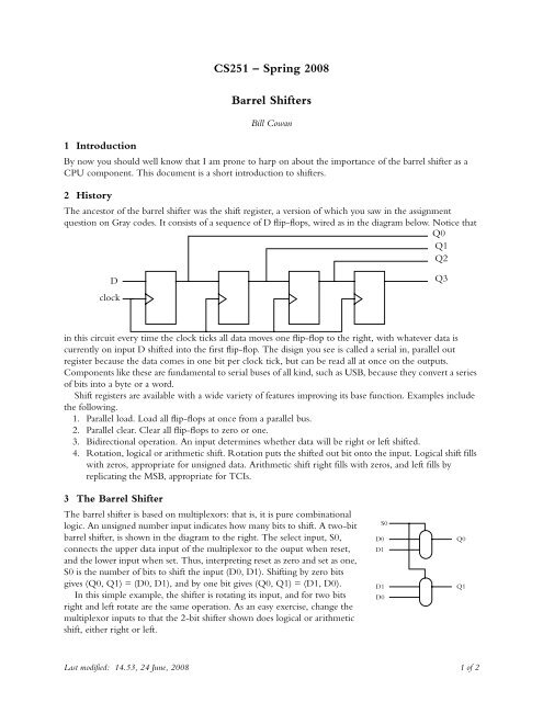
2 History<br />
The ancestor of the barrel shifter was the shift register, a version of which you saw in the assignment<br />
question on Gray codes. It consists of a sequence of D flip-flops, wired as in the diagram below. Notice that<br />
Q0<br />
Q1<br />
Q2<br />
D<br />
clock<br />
in this circuit every time the clock ticks all data moves one flip-flop to the right, with whatever data is<br />
currently on input D shifted into the first flip-flop. The disign you see is called a serial in, parallel out<br />
register because the data comes in one bit per clock tick, but can be read all at once on the outputs.<br />
Components like these are fundamental to serial buses of all kind, such as USB, because they convert a series<br />
of bits into a byte or a word.<br />
Shift registers are available with a wide variety of features improving its base function. Examples include<br />
the following.<br />
1. Parallel load. Load all flip-flops at once from a parallel bus.<br />
2. Parallel clear. Clear all flip-flops to zero or one.<br />
3. Bidirectional operation. An input determines whether data will be right or left shifted.<br />
4. Rotation, logical or arithmetic shift. Rotation puts the shifted out bit onto the input. Logical shift fills<br />
with zeros, appropriate for unsigned data. Arithmetic shift right fills with zeros, and left fills by<br />
replicating the MSB, appropriate for TCIs.<br />
3 The <strong>Barrel</strong> Shifter<br />
The barrel shifter is based on multiplexors: that is, it is pure combinational<br />
logic. An unsigned number input indicates how many bits to shift. A two-bit<br />
barrel shifter, is shown in the diagram to the right. The select input, S0,<br />
connects the upper data input of the multiplexor to the ouput when reset,<br />
and the lower input when set. Thus, interpreting reset as zero and set as one,<br />
S0 is the number of bits to shift the input (D0, D1). Shifting by zero bits<br />
gives (Q0, Q1) = (D0, D1), and by one bit gives (Q0, Q1) = (D1, D0).<br />
In this simple example, the shifter is rotating its input, and for two bits<br />
right and left rotate are the same operation. As an easy exercise, change the<br />
multiplexor inputs to that the 2-bit shifter shown does logical or arithmetic<br />
shift, either right or left.<br />
Last modified: 14.53, 24 June, <strong>2008</strong> 1 of 2<br />
S0<br />
D0<br />
D1<br />
D1<br />
D0<br />
Q3<br />
Q0<br />
Q1
Suppose now that we<br />
have four bit data, and<br />
we want to do three<br />
operations on this data,<br />
rotate, logical shift and<br />
arithmetic shift, each<br />
one either right or left.<br />
We can create such a<br />
shifter using two<br />
selector, four- bit<br />
multiplexors, as shown<br />
immediately to the<br />
right. On the far right<br />
the top three 1/2<br />
multiplexors implement<br />
the topmost 2/4<br />
multiplexor. In practice,<br />
barrel shifters are usually<br />
constructed from a large<br />
number of 1/2<br />
multiplexors. Why? The<br />
second group of three<br />
multiplexors calculates<br />
the second bit of the<br />
shifted result, the circuit<br />
being more or less<br />
independent of the one<br />
that calculated the first<br />
S0-1<br />
D0-3<br />
S0-1<br />
D0-3<br />
S0-1<br />
D0-3<br />
S0-1<br />
D0-3<br />
Q0<br />
Q1<br />
Q2<br />
Q3<br />
bit of the shifted result. But now, the remaining two bits requires only one multiplexor each, so the total<br />
number of multiplexors needed is eight insteda of twelve. This advantage increases as the number of bits<br />
increases.<br />
The illustration is a very specific barrel shifter, which rotates the value left. It is also possible, by<br />
introducing different inputs, to do logical or arithmetic shift, and to shift right instead of left.<br />
Nowadays barrel shifters are rarely seen as discrete<br />
components, but are combined with other components<br />
to make a CPU or more often a DSP. When they appear<br />
in block diagrams of circuits they are most often given a<br />
symbol like the one illustrated to the right. (The actual<br />
part shown is part of a LSH32, 32-bit barrel shifter.<br />
SFT0-4 gives the number of bits to be shifted; WRAP/<br />
FILL determines whether the operation is a rotation<br />
(WRAP) or a shift (FILL), and when the operation is a<br />
shift LEFT/RIGHT determines the direction of the<br />
shift.)<br />
Last modified: 14.53, 24 June, <strong>2008</strong> 2 of 2<br />
S0<br />
D0<br />
D1<br />
D2<br />
D3<br />
D3<br />
D0<br />
D1<br />
D2<br />
SFT0-4<br />
WRAP/FILL<br />
LEFT/RIGHT<br />
S1<br />
in<br />
32<br />
out<br />
32<br />
Q0<br />
Q1<br />
Q2<br />
Q3