Fire Protection Design Manual - Office of Construction and Facilities ...
Fire Protection Design Manual - Office of Construction and Facilities ...
Fire Protection Design Manual - Office of Construction and Facilities ...

Create successful ePaper yourself
Turn your PDF publications into a flip-book with our unique Google optimized e-Paper software.
Department <strong>of</strong><br />
Veterans Affairs<br />
FIRE PROTECTION<br />
DESIGN MANUAL<br />
Sixth Edition - September 2011<br />
<strong>Office</strong> <strong>of</strong> Safety, Health, <strong>and</strong> Environmental Compliance (10NA8)
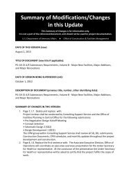
Summary <strong>of</strong> significant changes to the 6 th edition <strong>of</strong> the VA <strong>Fire</strong> <strong>Protection</strong> <strong>Design</strong> <strong>Manual</strong><br />
A. Clarified building construction type <strong>and</strong> building separation requirements (see Ch 2).<br />
B. Clarified requirements for parking garages (see Ch 2).<br />
C. Clarified door locking criteria to comply with NFPA 101 (see Ch 2).<br />
D. Clarified requirements for data centers (wet pipe sprinkler protection continues to be required) (see<br />
Ch 3).<br />
E. Clarified water supply requirements to coincide with latest Physical Security <strong>Design</strong> <strong>Manual</strong> (see Ch<br />
5)<br />
F. Clarified requirements for sprinkler systems (see Ch 6), including<br />
• Restrictions on use <strong>of</strong> CPVC sprinkler piping<br />
• Permission to use NFPA 13R <strong>and</strong> NFPA 13D for residential occupancies<br />
• Sprinkler requirements for clean rooms<br />
• Permission to use sprinklers that are not FM-approved for special cases<br />
• Permission to use st<strong>and</strong>ard response sprinklers (in lieu <strong>of</strong> quick response) for special cases<br />
G. Clarified fire alarm system wiring designations to coordinate with current edition <strong>of</strong> NFPA 72 (see Ch<br />
7)<br />
2. Most <strong>of</strong> the changes mentioned above were intended to clarify existing criteria. We do not anticipate<br />
that revisions to the 6 th edition <strong>of</strong> the VA <strong>Fire</strong> <strong>Protection</strong> <strong>Design</strong> <strong>Manual</strong> will result in significant changes<br />
to projects in progress. Where significant issues arise as a result <strong>of</strong> revisions in the 6 th edition, such<br />
issues should be directed to this <strong>of</strong>fice (10NA8).<br />
3. Implementation guidance with respect to the NFPA <strong>Fire</strong> Codes is provided in section 1.3.b as follows:<br />
<strong>Fire</strong> <strong>Protection</strong> design shall be based on the latest editions <strong>of</strong> the NFC at the Date <strong>of</strong> Award<br />
<strong>of</strong> the contract to the Architectural/Engineering (A/E) firm (or <strong>Design</strong>/Build firm). Under<br />
special circumstances, the VA will require compliance with a more recent code edition when<br />
significant changes to the code have occurred between the Date <strong>of</strong> Award to the A/E <strong>and</strong><br />
the Date <strong>of</strong> Award to the prime contractor for construction.<br />
Note: Special circumstances would include a situation where a designed project sat “on the<br />
shelf” for an extended period <strong>of</strong> time, or where a significant change to the code was made<br />
<strong>and</strong> where incorporating that change would improve safety in the opinion <strong>of</strong> the AHJ.<br />
4. With respect to application across VA, the VA <strong>Fire</strong> <strong>Protection</strong> <strong>Design</strong> <strong>Manual</strong> is intended to apply to<br />
all VA projects (VHA, VBA, NCA, OIT, etc).<br />
Additional modifications include making document Section 508 accessible for posting on Internet,<br />
including latest seismic map, <strong>and</strong> updating mail code symbols for CFM.
FIRE PROTECTION DESIGN MANUAL<br />
DEPARTMENT OF VETERANS AFFAIRS<br />
TABLE OF CONTENTS<br />
September-2011<br />
INTRODUCTION....................................................................................................................................... 1<br />
1. GENERAL............................................................................................................................................ 1<br />
1.1 SCOPE ............................................................................................................................................. 1<br />
1.2 APPLICATION .................................................................................................................................. 1<br />
1.3 FIRE PROTECTION CODES AND STANDARDS................................................................................... 2<br />
1.4 FIRE PROTECTION DURING CONSTRUCTION................................................................................... 3<br />
1.5 AMERICANS WITH DISABILITIES ACT (ADA)................................................................................. 3<br />
2. BUILDING FEATURES..................................................................................................................... 4<br />
2.2 VA HOSPITAL BUILDING SYSTEM (INTERSTITIAL)......................................................................... 5<br />
2.3 INTERIOR FINISH............................................................................................................................. 6<br />
2.5 SITE CONSIDERATIONS ................................................................................................................... 6<br />
2.6 INSULATION, INCLUDING FOAM PLASTIC ........................................................................................ 6<br />
2.7 ROOF COVERINGS AND ROOF DECK ASSEMBLIES ......................................................................... 6<br />
2.8 ROOF ACCESS ................................................................................................................................. 6<br />
2.9 SHELTERS, PAVILIONS, CONNECTING CORRIDORS OR SIMILAR STRUCTURES LOCATED NEAR<br />
HEALTH CARE BUILDINGS .......................................................................................................................... 6<br />
2.10 FIRE AND SMOKE BARRIERS:...................................................................................................... 7<br />
2.11 PROTECTION OF OPENINGS: ........................................................................................................ 7<br />
2.12 SUITES ......................................................................................................................................... 7<br />
2.13 EXIT SIGNS.................................................................................................................................. 7<br />
2.14 DOOR LOCKING REQUIREMENTS ................................................................................................ 7<br />
3. SPECIAL PROTECTION................................................................................................................ 10<br />
3.1 STORAGE....................................................................................................................................... 10<br />
3.2 FLAMMABLE AND COMBUSTIBLE LIQUID STORAGE..................................................................... 10<br />
3.3 FOOD PREPARATION FACILITIES................................................................................................... 10<br />
3.4 COMPRESSED GAS/CRYOGENIC LIQUID STORAGE ....................................................................... 10<br />
3.5 LABORATORIES............................................................................................................................. 10<br />
3.6 CASEWORK (INCLUDING NON-MOVEABLE, BUILT-IN CABINETRY, WARDROBE, ETC.)................. 10<br />
3.7 INFORMATION TECHNOLOGY TELECOMMUNICATION, AND HIGH COST EQUIPMENT ROOMS:.... 11<br />
3.8 PAINT SPRAY AREAS .................................................................................................................... 12<br />
3.9 ATRIUM SMOKE CONTROL SYSTEMS ........................................................................................... 12<br />
3.10 VA CANTEEN RETAIL STORES .................................................................................................. 12<br />
3.11 PHARMACIES ............................................................................................................................. 12<br />
3.12 CHUTES ..................................................................................................................................... 12<br />
4. OCCUPANCY CLASSIFICATION ................................................................................................ 13<br />
4.1 GENERAL ...................................................................................................................................... 13<br />
4.2 MULTIPLE (MIXED) OCCUPANCIES .............................................................................................. 13<br />
- ii
September-2011<br />
5. WATER SUPPLY FOR FIRE PROTECTION.............................................................................. 16<br />
5.1 ADEQUACY OF WATER SUPPLY.................................................................................................... 16<br />
5.2 CAPACITY ..................................................................................................................................... 16<br />
5.3 FIRE PUMPS .................................................................................................................................. 17<br />
5.4 DURATION..................................................................................................................................... 18<br />
5.5 DISTRIBUTION SYSTEM................................................................................................................. 18<br />
5.6 HYDRANTS.................................................................................................................................... 19<br />
5.7 SIGNAGE ....................................................................................................................................... 19<br />
6. FIRE EXTINGUISHING SYSTEMS.............................................................................................. 20<br />
6.1 SPRINKLER SYSTEMS.................................................................................................................... 20<br />
6.2 STANDPIPES AND FIRE HOSE CONNECTIONS................................................................................ 26<br />
6.3 GASEOUS SYSTEMS (CLEAN AGENT, CARBON DIOXIDE ETC.)..................................................... 27<br />
6.4 PORTABLE FIRE EXTINGUISHERS.................................................................................................. 27<br />
6.5 EXTINGUISHING SYSTEMS FOR COOKING FACILITIES/EQUIPMENT ............................................... 27<br />
7. FIRE ALARM SYSTEMS................................................................................................................ 28<br />
7.1 PURPOSE ....................................................................................................................................... 28<br />
7.2 GENERAL REQUIREMENTS............................................................................................................ 28<br />
7.3 TYPICAL OPERATION .................................................................................................................... 29<br />
TABLE 7.3 <strong>Fire</strong> Alarm System Input Output Matrix........................................................................... 30<br />
7.4 SPECIAL REQUIREMENTS .............................................................................................................. 36<br />
7.5 COMMUNICATIONS BETWEEN BUILDINGS .................................................................................... 43<br />
APPENDIX A............................................................................................................................................ 44<br />
ABBREVIATIONS USED IN THIS DESIGN MANUAL ................................................................................... 44<br />
APPENDIX B ............................................................................................................................................ 46<br />
MANDATORY REFERENCES ..................................................................................................................... 46<br />
ADDITIONAL REFERENCES ...................................................................................................................... 46<br />
APPENDIX C............................................................................................................................................ 47<br />
APPLICABLE DESIGN AND CONSTRUCTION CRITERIA............................................................................. 47<br />
Master Specifications (PG-18-1)......................................................................................................... 47<br />
<strong>Design</strong> <strong>and</strong> <strong>Construction</strong> Procedures (PG-18-03).............................................................................. 47<br />
St<strong>and</strong>ard Details (PG-18-04) .............................................................................................................. 47<br />
Other VA Criteria................................................................................................................................ 48<br />
APPENDIX D............................................................................................................................................ 50<br />
VA DESIGN MANUALS ............................................................................................................................ 50<br />
VA DESIGN GUIDES ................................................................................................................................ 50<br />
INDEX........................................................................................................................................................ 51<br />
- iii
FIRE PROTECTION DESIGN MANUAL<br />
DEPARTMENT OF VETERANS AFFAIRS<br />
September-2011<br />
INTRODUCTION<br />
The primary goal <strong>of</strong> this manual is to provide an environment for occupants that is reasonably safe from<br />
fire <strong>and</strong> products <strong>of</strong> combustion. To achieve this goal, the objectives are to protect occupants who are not<br />
intimate with initial fire development for the time needed to take appropriate action, <strong>and</strong> to improve the<br />
survivability <strong>of</strong> occupants who are intimate with initial fire development.<br />
The secondary goals <strong>of</strong> this manual are to provide a reasonable level <strong>of</strong> building usability <strong>and</strong> property<br />
protection from the effects <strong>of</strong> fire <strong>and</strong> products <strong>of</strong> combustion. To achieve these goals, the objectives are<br />
to increase the likelihood that, in the event <strong>of</strong> a fire, critical operational functions are not interrupted for<br />
longer than 24 hours <strong>and</strong> the loss <strong>of</strong> real or personal property does not exceed $500,000.00.<br />
The criteria in this manual are based on the assumption <strong>of</strong> a single fire source.<br />
1. GENERAL<br />
1.1 Scope:<br />
A. This manual contains fire protection engineering design criteria to meet the goals identified<br />
above, by protecting patients, visitors, <strong>and</strong> staff; maintaining the continuity <strong>of</strong> important<br />
clinical <strong>and</strong> administrative activities; <strong>and</strong> protecting VA property. This generally will<br />
require the installation <strong>of</strong> automatic sprinkler protection in VA owned buildings. In VA<br />
occupied buildings, sprinkler protection shall be required to protect VA property or for<br />
compliance with the Life Safety Code or the Federal <strong>Fire</strong> Safety Act PL-102-522. See<br />
Section 6.1. (Note: <strong>Protection</strong> shall not be required to limit the loss <strong>of</strong> non-VA property.)<br />
B. This manual applies to all categories <strong>of</strong> VA construction <strong>and</strong> renovation projects, station<br />
level projects, <strong>and</strong> acquisition <strong>of</strong> all VA property (including leases).<br />
C. This manual supersedes new construction criteria contained in VA Circulars, Information<br />
Letters, <strong>and</strong> Directives, which are dated prior to the publication date <strong>of</strong> this manual.<br />
D. This manual is intended to apply to new construction. It can be used as guidance with<br />
respect to existing features.<br />
1.2 Application:<br />
A. Use this manual in conjunction with the Scope <strong>of</strong> Work paragraph in the Architect/Engineer<br />
(A/E) Package <strong>and</strong> PG-18-15, Minimum Requirements for A/E Submissions, which defines<br />
the information to be shown on drawings <strong>and</strong> work to be completed at each stage <strong>of</strong> design.<br />
In addition, coordinate with requirements from other applicable VA criteria listed in<br />
Appendices C <strong>and</strong> D.<br />
B. The facility shall solicit the services <strong>of</strong> a third party with knowledge <strong>of</strong> applicable fire<br />
protection criteria such as the respective Network Safety Manager, Network Safety <strong>and</strong> <strong>Fire</strong><br />
<strong>Protection</strong> Engineer (SFPE), or other qualified fire protection engineering consultant during<br />
design in order to insure the project as designed by the A/E complies with such criteria.<br />
Obtaining these third party services early in the design process is strongly recommended.<br />
The third party entity shall be involved in reviewing the design, but may also be involved<br />
with reviewing contractor’s submissions, conducting pre-occupancy life safety inspections,<br />
<strong>and</strong>/or witnessing final fire protection acceptance testing.<br />
- 1
September-2011<br />
C. For code interpretation <strong>and</strong> enforcement, the Authority Having Jurisdiction (AHJ) for all VA<br />
projects is ultimately the Deputy Under Secretary for Health for Operations <strong>and</strong> Management<br />
(10N), with the Safety <strong>and</strong> <strong>Fire</strong> <strong>Protection</strong> Engineer (10NA8) acting as the VA <strong>Fire</strong> Marshal.<br />
At the Medical Center <strong>and</strong> Veterans Integrated Service Network (VISN) level, the respective<br />
Network Safety Manager or Network Safety <strong>and</strong> <strong>Fire</strong> <strong>Protection</strong> Engineer (SFPE) has the<br />
option to act as the AHJ representative on behalf <strong>of</strong> 10NA8 <strong>and</strong> make local AHJ decisions in<br />
areas where they are competent.<br />
1.3 <strong>Fire</strong> <strong>Protection</strong> Codes <strong>and</strong> St<strong>and</strong>ards:<br />
A. The Public Buildings Amendment Act (PL 100-678) requires all federal agencies to follow<br />
the latest editions <strong>of</strong> nationally recognized fire <strong>and</strong> life safety codes. It also requires federal<br />
agencies to give local fire protection <strong>of</strong>ficials the opportunity to review <strong>and</strong> comment on<br />
projects for compliance with local regulations <strong>and</strong> compatibility with local fire fighting<br />
practices. All reviews by local fire protection <strong>of</strong>ficials shall be at no cost to the Government.<br />
<strong>Design</strong>ers should meet with local fire authorities during early stages <strong>of</strong> design to incorporate<br />
local requirements to the extent practical; however, recommendations made by local <strong>of</strong>ficials<br />
should be reviewed for adequacy, cost, <strong>and</strong> nationally accepted practice before being<br />
incorporated into project design.<br />
B. VA has adopted the National <strong>Fire</strong> Codes (NFC) published by the National <strong>Fire</strong> <strong>Protection</strong><br />
Association (NFPA), which establish a minimum acceptable level <strong>of</strong> life safety <strong>and</strong> property<br />
protection. Life safety requirements are specifically addressed in the Life Safety Code,<br />
NFPA 101. Where conflicts exist between codes, the designer shall follow the code<br />
specified in the text under the subject section <strong>of</strong> this manual. <strong>Fire</strong> <strong>Protection</strong> design shall be<br />
based on the latest editions <strong>of</strong> the NFC at the Date <strong>of</strong> Award <strong>of</strong> the contract to the<br />
Architectural/Engineering (A/E) firm (or <strong>Design</strong>/Build firm). Under special circumstances,<br />
the VA will require compliance with a more recent code edition when significant changes to<br />
the code have occurred between the Date <strong>of</strong> Award to the A/E <strong>and</strong> the Date <strong>of</strong> Award to the<br />
prime contractor for construction.<br />
Note: Special circumstances would include a situation where a designed project sat “on the<br />
shelf” for an extended period <strong>of</strong> time, or where a significant change to the code was made<br />
<strong>and</strong> where incorporating that change would improve safety in the opinion <strong>of</strong> the AHJ.<br />
C. <strong>Fire</strong> protection features not addressed by the NFC or otherwise addressed by this document<br />
shall be designed to comply with the requirements <strong>of</strong> the latest edition <strong>of</strong> the International<br />
Building Code (IBC). Other references are listed in Appendix B.<br />
D. For design features that are addressed by both the IBC as well as by NFPA 101 or a<br />
document referenced by NFPA 101, the requirements <strong>of</strong> NFPA 101 or the document<br />
referenced by NFPA 101 shall be used exclusively (this applies even if the IBC requirements<br />
are different).<br />
Note: VA buildings must meet the requirements <strong>of</strong> NFPA 101 <strong>and</strong> documents referenced by<br />
NFPA 101 in order to comply with the accreditation requirements <strong>of</strong> the Joint Commission.<br />
It is intended that life safety <strong>and</strong> fire protection features will be designed in accordance with<br />
the requirements <strong>of</strong> NFPA 101 <strong>and</strong> documents referenced by NFPA 101. Other building<br />
features (including, but not limited to, structural strength, stability, sanitation, adequate<br />
light <strong>and</strong> ventilation, <strong>and</strong> energy conservation) will be designed in accordance with the IBC<br />
<strong>and</strong> documents referenced by the IBC or as identified in VHA Program Guide PG-18-3,<br />
Topic 1 – Codes, St<strong>and</strong>ards, <strong>and</strong> Executive Orders.<br />
- 2
September-2011<br />
E. Strict compliance to codes <strong>and</strong> st<strong>and</strong>ards is m<strong>and</strong>atory for new construction. If equivalent<br />
protection is proposed by the designer for renovations, submit requests <strong>and</strong> supporting<br />
rationale through the respective Network Safety Manager or SFPE to the Safety <strong>and</strong> <strong>Fire</strong><br />
<strong>Protection</strong> Engineer (10NA8) in VA Central <strong>Office</strong>.<br />
1.4 <strong>Fire</strong> <strong>Protection</strong> During <strong>Construction</strong>:<br />
A. Coordinate with the facility prior to <strong>and</strong> concurrent with design.<br />
B. <strong>Fire</strong> protection during construction shall comply with VA Master <strong>Construction</strong> Specification<br />
(VAMCS) 01 00 00, General Requirements. (Note: VAMCS 01 00 00, General<br />
Requirements, addresses NFPA 241, Joint Commission Interim Life Safety Measures, Hot<br />
Work Permits, etc. This specification section was formerly section 01010.)<br />
C. Separate all occupied areas from demolition, renovation, or construction activities by<br />
temporary smoke-tight construction partitions <strong>of</strong> gypsum board or other approved noncombustible<br />
or limited-combustible material. Partitions shall be full height, extending<br />
through suspended ceilings to the floor slab or ro<strong>of</strong> deck above <strong>and</strong> shall be one-hour fire<br />
rated, unless sprinklers are installed <strong>and</strong> are operational on both sides <strong>of</strong> the temporary<br />
partition whereupon the partition may be permitted to terminate at the ceiling in accordance<br />
with NFPA 241. Where the ceiling on one side <strong>of</strong> the temporary construction barrier has<br />
been removed, the temporary partition must extend to the deck above.<br />
Note: This requirement is due to the inherently greater potential for fire or hazardous<br />
materials incidents associated with the combustibles <strong>and</strong> operations <strong>of</strong><br />
demolition/construction. This risk is made worse by the likelihood <strong>of</strong> compromised fire<br />
protection systems <strong>and</strong> fire/smoke resistant construction. This does not obviate the need to<br />
provide other protective measures to contain dust <strong>and</strong> debris as specified by VAMCS 01 00<br />
00 section 1.8(D)(2). Sprinklers are considered to be operational when they are installed in<br />
accordance with NFPA 13 (spacing, protection, distance from the ceiling, etc.) <strong>and</strong> there is a<br />
sufficient automatic water supply. If the ceiling was removed <strong>and</strong> the sprinklers remain at<br />
the original ceiling level, they would likely not be considered operational.<br />
D. Phase construction as necessary to ensure that obstruction <strong>of</strong> exits is minimized or avoided.<br />
If exits are obstructed during construction, provide alternate exit routes during each phase <strong>of</strong><br />
construction <strong>and</strong> identify the alternate routes on the construction drawings.<br />
E. Minimize or avoid disruptions to fire alarm <strong>and</strong> sprinkler systems. Delineate phasing <strong>of</strong><br />
construction to ensure that installations <strong>of</strong> new systems are expedited, <strong>and</strong> where possible,<br />
maintain existing systems in service until the replacement system is operational. If fire<br />
protection systems are to be disrupted, ensure procedures are incorporated to maintain<br />
equivalent levels <strong>of</strong> fire protection <strong>and</strong> provide formal notification to the facility while<br />
systems are down.<br />
1.5 Americans with Disabilities Act (ADA): <strong>Fire</strong> <strong>Protection</strong> requirements <strong>of</strong> ADA do not apply to<br />
federal agencies; however, VA is required to comply with the ABA (Architectural Barriers Act)<br />
Accessibility St<strong>and</strong>ard for Federal <strong>Facilities</strong>.<br />
- 3
September-2011<br />
2. BUILDING FEATURES<br />
2.1 Types <strong>of</strong> <strong>Construction</strong>:<br />
A. For each construction type, design fire resistive ratings <strong>of</strong> structural members in accordance<br />
with NFPA 220.<br />
B. For other than parking garages, comply with the following:<br />
1) For buildings where NFPA 101 provides construction requirements for one or more <strong>of</strong><br />
the occupancies within the building, the type <strong>of</strong> construction as well as the height for the<br />
building shall comply with the most restrictive occupancy construction requirements <strong>of</strong><br />
NFPA 101.<br />
2) For buildings where NFPA 101 does not provide construction requirements for any <strong>of</strong><br />
the occupancies within the building, the construction type as well as height <strong>and</strong> area<br />
limitations for the building shall comply with the requirements <strong>of</strong> the IBC.<br />
Note: The height <strong>and</strong> area limitations found in the IBC will apply only to those buildings<br />
where all occupancies within the building have no construction requirements in NFPA 101.<br />
For example, use <strong>of</strong> the IBC will restrict the height <strong>and</strong> area <strong>of</strong> a Type V building containing<br />
a business occupancy while NFPA 101 would permit the building to be <strong>of</strong> unlimited height<br />
<strong>and</strong> area. Typically, new construction in the VA will require the building to be sprinkler<br />
protected <strong>and</strong> the limitations in the IBC for fully sprinkler protected buildings should not be<br />
overly restrictive.<br />
C. For parking garages, the construction type as well as height <strong>and</strong> area limitations shall be as<br />
follows:<br />
1) Portions that are open parking structures, as defined in NFPA 88A, shall be in<br />
accordance with NFPA 88A.<br />
2) Portions that are enclosed parking structures, as defined in NFPA 88A, shall be in<br />
accordance with the IBC.<br />
2.2 Building Separation:<br />
A. For other than parking garages, the requirements for fire resistance ratings <strong>of</strong> exterior walls,<br />
maximum area for exterior wall openings, <strong>and</strong> opening protection shall comply with the IBC<br />
(see Note 1) except as follows:<br />
1) There are no requirements for separation or openings between VA buildings when both<br />
(all) buildings are fully sprinkler protected (see Notes 2 <strong>and</strong> 3). This exception does not<br />
apply to VA buildings that are adjacent to non-VA property lines.<br />
2) As permitted under Section 2.9 <strong>of</strong> this design manual.<br />
Note 1: Building separation requirements are found in Table 602 <strong>and</strong> opening requirements<br />
are found in Table 705.8 <strong>of</strong> the 2009 Edition <strong>of</strong> the IBC. With greater than 60 feet <strong>of</strong><br />
separation between buildings (or greater than 30 feet <strong>of</strong> separation between a building <strong>and</strong> a<br />
property line), there are no requirements in the IBC. With ≤ 60 feet <strong>of</strong> separation between<br />
buildings (or ≤ 30 feet <strong>of</strong> separation between a building <strong>and</strong> a property line) <strong>and</strong> where any<br />
one building is not fully sprinkler protected, the requirements in the IBC must be followed.<br />
Note 2: Buildings that are sprinkler protected throughout are not considered to be an<br />
exposure hazard in accordance with NFPA 80A.<br />
- 4
September-2011<br />
Note 3: If buildings touch each other, additional requirements might apply. (i.e. construction<br />
type, occupancy separation, etc.)<br />
B. For parking garages, building separation <strong>and</strong> requirements for rated exterior walls <strong>and</strong><br />
openings shall comply with the requirements <strong>of</strong> NFPA 88A.<br />
2.3 VA Hospital Building System (Interstitial): <strong>Fire</strong> protection requirements for facilities designed<br />
using the VA Hospital Building System (VAHBS) shall comply with the following:<br />
A. <strong>Design</strong> walk-on decks in accordance with the lightweight insulating concrete assembly tested<br />
<strong>and</strong> reported in NBSIR 85-3158 or NISTIR 5560, except that sprayed fire-resistive material<br />
protecting the bottom <strong>of</strong> purlins supporting walk-on decks shall be sprayed to a minimum<br />
thickness <strong>of</strong> one-inch with firepro<strong>of</strong>ing suitable for exposed applications. Wire mesh may be<br />
omitted from the bottom flange <strong>of</strong> the purlins supporting the deck.<br />
B. Steel in interstitial space supporting functional floors shall not be firepro<strong>of</strong>ed, with the<br />
exception <strong>of</strong> columns, which are sprayed throughout their entire height, <strong>and</strong> structural<br />
members supporting mechanical room floors (required to maintain continuity <strong>of</strong> the two-hour<br />
membrane separating interstitial spaces from functional floors). Clearly identify these<br />
features on design details <strong>and</strong> in specifications.<br />
C. Two-hour fire resistance rating is required between floors; the separation runs in a horizontal<br />
plane along the mechanical equipment room floor, then vertically along the wall separating<br />
the mechanical equipment room from functional spaces, then it continues along the<br />
interstitial deck. Columns, girders, <strong>and</strong> trusses supporting more than one floor within<br />
interstitial spaces <strong>and</strong> structural members in the mechanical room shall also have two-hour<br />
fire resistance rating.<br />
D. Interstitial space need not be subdivided horizontally into fire or smoke compartments.<br />
Horizontal exits or smoke barrier walls located below in occupied space need not be<br />
extended up into interstitial space.<br />
E. In interstitial space, a fire resistive rating is only required for two-hour fire rated shafts<br />
(elevators, chases, stairs, etc.) <strong>and</strong> one-hour rated mechanical equipment rooms adjacent to<br />
interstitial spaces.<br />
F. Neither fire nor smoke dampers are required where ducts penetrate the one-hour rated<br />
partition separating the mechanical room from the interstitial space; however, smoke<br />
dampers are required at air h<strong>and</strong>lers to comply with NFPA 90A. <strong>Fire</strong> dampers are not<br />
required in ducts for openings in the interstitial deck less than 150,000 sq. mm (225 sq in),<br />
including supply ducts from interstitial spaces to functional spaces, exhaust ducts, <strong>and</strong> return<br />
ducts from functional spaces into the interstitial space. Flexible duct work (UL 181, Class I)<br />
is permitted in interstitial space for connections less than 2.4 m (8 ft) long <strong>and</strong> shall be no<br />
larger than 300 mm (12 in) diameter.<br />
G. Protect horizontal <strong>and</strong> vertical penetrations (ducts, cables, pipes, etc.) with through<br />
penetration protection systems.<br />
H. Provide fire alarm pull stations at exit doors from interstitial spaces <strong>and</strong> sufficient<br />
notification appliances so a fire alarm signal can be received throughout the spaces.<br />
I. Provide exit signs at exit doors <strong>and</strong> other locations to provide clear direction toward exits<br />
from interstitial spaces. Provide emergency lighting for adequate egress illumination in the<br />
event <strong>of</strong> a power outage.<br />
- 5
2.4 Interior Finish:<br />
A. Wall <strong>and</strong> ceiling finishes <strong>and</strong> movable partitions shall conform to NFPA 101.<br />
B. Interior floor finish shall conform to NFPA 101.<br />
September-2011<br />
2.5 Site Considerations:<br />
A. Provide access for emergency vehicles to new buildings <strong>and</strong> additions in accordance with<br />
NFPA 1.<br />
B. <strong>Design</strong> roads, fire lanes, <strong>and</strong> turn-arounds for the weight <strong>and</strong> turning radius <strong>of</strong> fire apparatus.<br />
Consult local fire department for fire apparatus requirements. At minimum, one <strong>of</strong> the long<br />
sides <strong>of</strong> every building shall be accessible to fire department equipment.<br />
2.6 Insulation, including foam plastic: Comply with IBC.<br />
2.7 Ro<strong>of</strong> Coverings <strong>and</strong> Ro<strong>of</strong> Deck Assemblies:<br />
A. Ro<strong>of</strong> coverings shall be approved or listed by a nationally recognized testing laboratory for<br />
compliance with UL st<strong>and</strong>ard 790 <strong>and</strong> shall be Class B minimum.<br />
B. Ro<strong>of</strong> deck assemblies shall be FM Class I approved, or shall be UL listed as <strong>Fire</strong>-Classified.<br />
2.8 Ro<strong>of</strong> Access: Comply with IBC.<br />
2.9 Shelters, pavilions, or similar structures located near health care buildings:<br />
A. Shelters or pavilions with automatic sprinkler protection are not considered to present an<br />
exposure hazard. However, if <strong>of</strong> wood-frame construction, they may not be attached directly<br />
to a permanent building.<br />
B. Locate non-sprinklered combustible structures or non-sprinklered structures that have<br />
combustible ro<strong>of</strong> assemblies a minimum <strong>of</strong> 7.5 m (25 ft) from the exposed building. The 7.5<br />
m (25 ft) separation may be reduced to 0 when the exposed (permanent) building has at least<br />
a two-hour fire resistive rating <strong>and</strong> has no openings (windows, doors, or ro<strong>of</strong>) within 7.5 m<br />
(25 ft) <strong>of</strong> the temporary structure; to 3 m (10 ft) when the exposed wall has a two-hour fire<br />
resistive rating <strong>and</strong> all openings within 7.5 m (25 ft) <strong>of</strong> the temporary structure are protected<br />
with one-hour protection; <strong>and</strong> to 4.5 m (15 ft) when all openings in the two-hour fire resistive<br />
rated exposed wall are protected with 3/4 hour rated assemblies.<br />
C. Because it is difficult to ignite polycarbonate <strong>and</strong> aluminum (bus stop type) shelters <strong>and</strong> they<br />
are likely to collapse shortly after becoming fully involved in a fire, they are given special<br />
consideration. Polycarbonate <strong>and</strong> aluminum shelters located next to buildings with<br />
automatic sprinkler protection shall be located 3 m (10 ft) or more from any unprotected<br />
openings. Such shelters located next to buildings without automatic sprinkler protection<br />
shall be located 6 m (20 ft) or more from any unprotected openings.<br />
D. Shelters or pavilions that are <strong>of</strong> masonry construction shall not be located within 3 m (10 ft)<br />
<strong>of</strong> any building opening.<br />
- 6
September-2011<br />
2.10 <strong>Fire</strong> <strong>and</strong> Smoke Barriers: <strong>Fire</strong> <strong>and</strong> Smoke barriers shall be provided as required by NFPA<br />
101. In accordance with PG-18-15, fire <strong>and</strong> smoke barriers shall be shown on all drawings.<br />
Specifically indicate the hourly rating <strong>of</strong> every barrier. Where possible, smoke barriers<br />
should not be configured to include corridor doors.<br />
Note: Corridor walls <strong>and</strong> smoke barriers have different requirements.<br />
2.11 <strong>Protection</strong> <strong>of</strong> Openings: Openings in fire rated barriers shall be protected according to NFPA<br />
101, 80, <strong>and</strong> 90A. Doors in such openings shall be normally closed, unless equipped with<br />
electromagnetic door hold open devices arranged to close upon activation <strong>of</strong> the fire alarm<br />
system or smoke detector installed proximate to the door. <strong>Fire</strong> shutters shall be provided to<br />
protect openings in fire rated barriers designed to be normally open. Shutters shall be<br />
designed to close upon activation <strong>of</strong> a smoke detector proximate to the shutter. Such<br />
detectors shall close all shutters within a fire barrier served. Closing speed shall be in<br />
accordance with NFPA 80. <strong>Fire</strong> dampers shall be installed in fire rated barriers in<br />
accordance with NFPA 90A. <strong>Fire</strong> rating glazing, where used, shall meet applicable safety<br />
st<strong>and</strong>ards.<br />
Note: Shutter includes rolling steel fire doors as well as service counter doors.<br />
2.12 Suites: Corridor doors accessing suites in health care occupancies shall latch except power<br />
operated doors as identified in the Life Safety Code.<br />
Note: The intent <strong>of</strong> this requirement is to ensure corridor doors accessing suites are<br />
equipped with latches just like other corridor doors. This would apply even if the suite doors<br />
were part <strong>of</strong> a smoke barrier, though this configuration is not advised. Often, operating<br />
room, ICU <strong>and</strong> recovery room suite doors are double leaf power operated automatic doors<br />
that do not normally latch. As <strong>of</strong> the 2009 Edition <strong>of</strong> the Life Safety Code, these doors do not<br />
have to latch provided there is 5lbf at the latch edge that will keep the door closed.<br />
2.13 Exit Signs:<br />
A. Two exit signs are not required to be visible in an exit access corridor (see Healthcare<br />
Interpretations Task Force (HITF) 98-7).<br />
B. Exit signs with tritium are not permitted in VA facilities.<br />
Note: Possession <strong>of</strong> tritium exit signs brings upon the facility legal responsibilities for<br />
compliance with Nuclear Regulatory Commission (NRC) regulations.<br />
2.14 Door Locking Requirements: Doors are permitted to be locked in the direction <strong>of</strong> egress<br />
travel under conditions as identified in NFPA 101 (2009) as follows:<br />
A. Delayed Egress (7.2.1.6.1) where permitted by the occupancy chapter.<br />
B. Access Controlled (7.2.1.6.2) where permitted by the occupancy chapter.<br />
C. Elevator Lobbies (7.2.1.6.3) where permitted by the occupancy chapter.<br />
D. For the safety <strong>of</strong> the patients in healthcare occupancies<br />
1) Patient room doors (18/19.2.2.2.2)<br />
2) Means <strong>of</strong> egress for the clinical needs <strong>of</strong> the patients (18/19.2.2.2.5.1)<br />
Where the permission to lock doors in accordance with NFPA 101, 18/19.2.2.2.5.1 is<br />
used, NFPA 101, 18/19.2.2.2.6 requires the following:<br />
- 7
September-2011<br />
Doors that are located in the means <strong>of</strong> egress <strong>and</strong> are permitted to be locked under<br />
other provisions <strong>of</strong> this chapter shall have provisions made for the rapid removal <strong>of</strong><br />
occupants by means such as the follows:<br />
Option A. Remote control <strong>of</strong> locks<br />
Option B. Keying <strong>of</strong> all locks to keys carried by staff at all times<br />
Option C. Other such reliable means available to the staff at all times.<br />
VA Clarification for Options A, B, <strong>and</strong> C above:<br />
For Option (A): The locked doors are required to be in the line <strong>of</strong> sight <strong>of</strong> the<br />
location <strong>of</strong> the remote operator.<br />
For Option (B): Self evident<br />
For Option (C): Card access security systems may be used provided that a<br />
mechanical key release is provided such that when the key is operated, it will directly<br />
interrupt the power to the locking mechanism independent <strong>of</strong> the card access system<br />
electronics <strong>and</strong> staff in the area carry keys at all times.<br />
3) Means <strong>of</strong> egress where patient special needs require specialized protective measures<br />
(18/19.2.2.2.5.2)<br />
Note: This locking permission was added in the 2009 edition <strong>of</strong> the Life Safety Code<br />
especially for pediatric wards. Pediatric wards were being locked to prevent babies from<br />
being stolen <strong>and</strong> the locking was not truly for the clinical needs <strong>of</strong> the patients. The use <strong>of</strong><br />
section 18/19.2.2.2.5.2 should rarely be used in the VA since the doors could be locked under<br />
the less stringent requirements for clinical reasons on 18/19.2.2.2.5.1.<br />
Addition criteria from NFPA 101 as follows {(1) through (5)(b) copied verbatim} is<br />
required to use this arrangement.<br />
(1) Staff can readily unlock doors at all times in accordance with 18/19.2.2.2.6.<br />
(2) A total (complete) smoke detection system is provided throughout the locked<br />
space in accordance with 9.6.2.9, or locked doors can be remotely unlocked at an<br />
approved, constantly attended location within the locked space.<br />
(3)The building is protected throughout by an approved, supervised automatic<br />
sprinkler system in accordance with 18/19.3.5.1.<br />
(4) The locks are electrical locks that fail safely so as to release upon loss <strong>of</strong> power to<br />
the device.<br />
(5) The locks release by independent activation <strong>of</strong> each <strong>of</strong> the following:<br />
(a) Activation <strong>of</strong> the smoke detection system required by 18/19.2.2.2.5.2(2)<br />
(b) Waterflow in the automatic sprinkler system required by 18/19.2.2.2.5.2(3)<br />
Where the permission to lock doors in accordance with NFPA 101, 18/19.2.2.2.5.2 is<br />
used, NFPA 101, 18/19.2.2.2.6 requires the following:<br />
Doors that are located in the means <strong>of</strong> egress <strong>and</strong> are permitted to be locked under<br />
other provisions <strong>of</strong> this chapter shall have provisions made for the rapid removal <strong>of</strong><br />
occupants by means such as the follows:<br />
Option A. Remote control <strong>of</strong> locks<br />
- 8
Option B. Keying <strong>of</strong> all locks to keys carried by staff at all times<br />
Option C. Other such reliable means available to the staff at all times.<br />
VA Clarification for Options A, B, <strong>and</strong> C above:<br />
September-2011<br />
For Option (A): The locked doors are required to be in the line <strong>of</strong> sight <strong>of</strong> the<br />
location <strong>of</strong> the remote operator.<br />
For Option (B): Self evident<br />
For Option (C): Card access security systems may be used provided that a<br />
mechanical key release is provided such that when the key is operated, it will directly<br />
interrupt the power to the locking mechanism independent <strong>of</strong> the card access system<br />
electronics <strong>and</strong> staff in the area carry keys at all times.<br />
4) Doors in non-healthcare occupancies for the safety <strong>of</strong> patients (18/19.1.2.6)<br />
Note: From the NFPA 101 H<strong>and</strong>book: Health care occupancy patients are sometimes<br />
moved to nonmedical areas — such as a chapel for religious services or an auditorium for<br />
recreation — that typically do not meet the provisions applicable to health care occupancies.<br />
Paragraph 18/19.1.2.6 permits such areas to be regulated by the provisions applicable to the<br />
corresponding occupancy (which would be an assembly occupancy, in the case <strong>of</strong> chapels or<br />
auditoriums). This paragraph addresses a subject similar to that addressed in 18/19.1.2.7<br />
but adds the requirement that, where the clinical needs <strong>of</strong> the occupants necessitate the<br />
locking <strong>of</strong> doors, staff must be present for the supervised unlocking <strong>of</strong> doors <strong>and</strong> release <strong>of</strong><br />
occupants. This additional requirement ensures that procedures are in place for the ready<br />
release <strong>of</strong> occupants.<br />
- 9
September-2011<br />
3. SPECIAL PROTECTION<br />
3.1 Storage:<br />
A. Storage rooms shall be considered hazardous areas <strong>and</strong> shall comply with appropriate<br />
occupancy chapter requirements <strong>of</strong> NFPA 101.<br />
Note: It is not the intent to require protection for storage rooms that is greater than the<br />
protection required by the Life Safety Code. A storage room may be classified as a<br />
hazardous area in one occupancy chapter <strong>and</strong> not be considered a hazardous area in<br />
another occupancy chapter.<br />
B. Rooms containing medical records storage or moveable-aisle/mobile shelving shall be<br />
provided with automatic sprinkler protection <strong>and</strong> enclosed with a barrier having a one-hour<br />
fire resistance rating. Also see Section 6.1E.<br />
3.2 Flammable <strong>and</strong> Combustible Liquid Storage:<br />
A. Comply with NFPA 30.<br />
B. Provide adequate space for flammable <strong>and</strong> combustible liquid storage cabinets.<br />
3.3 Food Preparation <strong>Facilities</strong>: Provide fixed fire extinguishing systems for cooking operations in<br />
accordance with NFPA 96. Activation <strong>of</strong> the fire suppression system shall shut down the<br />
power/fuel source to the cooking equipment <strong>and</strong> shall be connected to the building fire alarm<br />
system. <strong>Fire</strong> protection systems shall be wet chemical type <strong>and</strong> shall comply with UL300 in<br />
accordance with NFPA 17A.<br />
3.4 Compressed Gas/Cryogenic Liquid Storage:<br />
A. Location, construction, <strong>and</strong> arrangement <strong>of</strong> compressed medical gas storage areas shall<br />
comply with NFPA 99.<br />
B. Bulk oxygen supply systems or storage locations having a total capacity <strong>of</strong> more than 566 cu<br />
m (20,000 cu ft) <strong>of</strong> oxygen shall comply with NFPA 50.<br />
C. Liquid oxygen storage tanks shall not be located on or within 4.5 m (15 ft) <strong>of</strong> asphalt or<br />
bituminous pavement. Provide non-combustible joints <strong>and</strong> crack fillers around these tanks.<br />
3.5 Laboratories:<br />
A. Do not locate laboratories containing Class I flammable liquids in basements.<br />
Note: Class I flammable liquids are not permitted in basements <strong>and</strong> are not permitted to be<br />
stored in basements, per NFPA 30, 2008 edition, sections 9.3.6 <strong>and</strong> 9.7.3.<br />
B. Laboratories using flammable or combustible liquids in buildings with inpatients, or<br />
outpatients incapable <strong>of</strong> self-preservation shall comply with NFPA 99. These laboratories<br />
shall be enclosed with a barrier having a one-hour fire resistance rating.<br />
Note: The type <strong>and</strong> quantities <strong>of</strong> flammable liquids are subject to change during the life <strong>of</strong><br />
the laboratory. For this reason, the added protection <strong>of</strong> a one-hour fire rated enclosure has<br />
been added.<br />
C. Other laboratories using flammable or combustible liquids shall comply with NFPA 45.<br />
3.6 Casework (including non-moveable, built-in cabinetry, wardrobe, etc.):<br />
A. No restrictions in buildings provided with automatic sprinkler protection.<br />
B. Provide metal casework in non-sprinklered buildings in patient care rooms.<br />
- 10
September-2011<br />
3.7 Information Technology Telecommunication, <strong>and</strong> High Cost Equipment Rooms:<br />
A. Mission-essential information technology, telecommunication, <strong>and</strong> high cost equipment<br />
rooms <strong>and</strong> infrastructure, with the potential for high dollar loss <strong>and</strong>/or business interruption,<br />
shall be provided with wet pipe automatic sprinkler protection <strong>and</strong> shall be designed to<br />
comply with NFPA 75 as described in this design manual.<br />
B. Additional guidance is provided in PG-18-3, VA <strong>Design</strong> <strong>and</strong> <strong>Construction</strong> Procedures, Topic<br />
10.<br />
C. Head End Equipment Rooms as defined in the VA Electrical <strong>Design</strong> <strong>Manual</strong> shall be<br />
provided with sprinkler protection <strong>and</strong> smoke detection.<br />
D. Telephone Equipment Rooms (TER) <strong>and</strong> Main Computer Rooms (MCR) as specified in the<br />
VA Electrical <strong>Design</strong> <strong>Manual</strong> are to be designed in accordance with Section 3.7 E, Data<br />
Centers. A Telephone Equipment Room is to be considered a Tier I facility.<br />
E. Data Centers:<br />
1. Tier I, Tier II, Tier III <strong>and</strong> Tier IV data centers are defined in “Data Center St<strong>and</strong>ards,”<br />
April 2004, VHA Enterprise Management Center, <strong>Office</strong> <strong>of</strong> Information. The following<br />
is extracted from that document:<br />
Tier I Data Center<br />
Basic<br />
A Tier I data center is susceptible to disruptions from both planned <strong>and</strong> unplanned activity. It has<br />
computer power distribution <strong>and</strong> cooling, but it may or may not have a raised floor, a UPS, or an<br />
engine generator. If it does have UPS or generators, they are single-module systems <strong>and</strong> have<br />
many single points <strong>of</strong> failure. The infrastructure should be completely shut down on an annual<br />
basis to perform preventive maintenance <strong>and</strong> repair work. Urgent situations may require more<br />
frequent shutdowns. Operation errors or spontaneous failures <strong>of</strong> site infrastructure components<br />
will cause a data center disruption.<br />
Tier II Data Center<br />
Redundant Components<br />
Tier II facilities with redundant components are slightly less susceptible to disruptions from both<br />
planned <strong>and</strong> unplanned activity than a basic data center. They have a raised floor, UPS, <strong>and</strong><br />
engine generators, but their capacity design is “Need plus One” (N+1), which has a singlethreaded<br />
distribution path throughout. Maintenance <strong>of</strong> the critical power path <strong>and</strong> other parts <strong>of</strong><br />
the site infrastructure will require a processing shutdown.<br />
Tier III Data Center<br />
Concurrently Maintainable<br />
Tier III level capability allows for any planned site infrastructure activity without disrupting the<br />
computer hardware operation in any way. Planned activities include preventive <strong>and</strong><br />
programmable maintenance, repair <strong>and</strong> replacement <strong>of</strong> components, addition or removal <strong>of</strong><br />
capacity components, testing <strong>of</strong> components <strong>and</strong> systems, <strong>and</strong> more. For large sites using chilled<br />
water, this means two independent sets <strong>of</strong> pipes.<br />
Sufficient capacity <strong>and</strong> distribution must be available to simultaneously carry the load on one<br />
path while performing maintenance or testing on the other path. Unplanned activities such as<br />
errors in operation or spontaneous failures <strong>of</strong> facility infrastructure components will still cause a<br />
data center disruption. Tier III sites are <strong>of</strong>ten designed to be upgraded to Tier IV when the<br />
client’s business case justifies the cost <strong>of</strong> additional protection.<br />
- 11
September-2011<br />
Tier IV Data Center<br />
Fault Tolerant<br />
Tier IV provides site infrastructure capacity <strong>and</strong> capability to permit any planned activity without<br />
disruption to the critical load. Fault-tolerant functionality also provides the ability <strong>of</strong> the site<br />
infrastructure to sustain at least one worst-case unplanned failure or event with no critical load<br />
impact. This requires simultaneously active distribution paths, typically in a System+System<br />
configuration. Electrically, this means two separate UPS systems in which each system has N+1<br />
redundancy. Because <strong>of</strong> fire <strong>and</strong> electrical safety codes, there will still be downtime exposure due<br />
to fire alarms or people initiating an Emergency Power Off (EPO). Tier IV requires all computer<br />
hardware to have dual power inputs as defined by the Institute’s Fault-Tolerance. Tier IV site<br />
infrastructures are the most compatible with high availability IT concepts that employ CPU<br />
clustering, RAID DASD, <strong>and</strong> redundant communications to achieve reliability, availability, <strong>and</strong><br />
serviceability.<br />
Current Vista facility data centers would fall into the first three tiers, with some being Tier-I <strong>and</strong><br />
very few at the Tier-III level. Ultimately, VA data center facilities should achieve an acceptable<br />
level <strong>of</strong> confidence (tier) within the VA’s infrastructure in order to support enterprise-level<br />
systems such as HealtheVet systems. In order to establish <strong>and</strong> implement a minimum level <strong>of</strong><br />
st<strong>and</strong>ards for VA data centers, a base set <strong>of</strong> st<strong>and</strong>ards must be established <strong>and</strong> used in a survey <strong>of</strong><br />
facility data centers.<br />
2. Tier I, II, III, <strong>and</strong> IV data centers shall be provided with wet pipe automatic sprinkler<br />
protection in accordance with NFPA 13. Sprinkler protection shall be installed utilizing<br />
st<strong>and</strong>ard response fusible link sprinklers.<br />
Note: St<strong>and</strong>ard response fusible link sprinklers will lessen the chance <strong>of</strong> a sprinkler<br />
being accidentally broken <strong>and</strong> will still provide structure protection since a st<strong>and</strong>ard<br />
response head is more robust <strong>and</strong> harder to break that a typical glass bulb quick<br />
response sprinkler.<br />
3. Tier I, II, III, <strong>and</strong> IV data centers shall be protected with a gaseous fire suppression<br />
system when required by NFPA 75. Note that a gaseous fire suppression system is in<br />
addition to, <strong>and</strong> does not replace, the required wet pipe automatic sprinkler system.<br />
Note: NFPA 75 provides risk criteria to establish the need for gaseous systems.<br />
Generally, Tier I systems would not require a gaseous system.<br />
3.8 Paint Spray Areas: Comply with NFPA 33.<br />
3.9 Atrium Smoke Control Systems: Comply with NFPA 92B. See the VA <strong>Design</strong> <strong>Manual</strong> for<br />
HVAC systems for additional design criteria.<br />
3.10 VA Canteen Retail Stores: Retail stores located in health care occupancies shall be<br />
considered as hazardous areas <strong>and</strong> shall therefore be separated from adjacent spaces by onehour<br />
fire rated construction.<br />
3.11 Pharmacies: Pharmacies located in health care occupancies shall be considered storage areas<br />
<strong>and</strong> shall therefore be separated from adjacent spaces by one-hour fire rated construction.<br />
<strong>Fire</strong> or service counter shutters shall be provided to protect openings where medication is<br />
dispensed or other transactions occur.<br />
3.12 Chutes: Linen chutes <strong>and</strong> waste chutes shall comply with the provisions in NFPA 82 for<br />
limited access gravity chutes.<br />
3.13 Parking Garages: Parking garages shall comply with the provisions in NFPA 88A except for<br />
construction type, height <strong>and</strong> area limitations, <strong>and</strong> building separation, which shall comply<br />
with 2.1. <strong>and</strong> 2.2 <strong>of</strong> this manual.<br />
- 12
4. OCCUPANCY CLASSIFICATION<br />
4.1 General: Occupancy classifications are defined in NFPA 101 <strong>and</strong> as follows:<br />
See also the attached file for occupancy determination. (Included at end <strong>of</strong> this document.)<br />
Health Care<br />
Chapter 18 & 20<br />
Business<br />
Chapter 38<br />
Hospitals Psychiatric Outpatient<br />
Clinics<br />
Nursing Homes Alcohol/Drug<br />
Outpatient <strong>Facilities</strong><br />
Ambulatory Health<br />
Care <strong>Facilities</strong> (1)<br />
Methadone<br />
Maintenance Clinics<br />
Alcohol/Drug (3) Ambulatory Health<br />
Care <strong>Facilities</strong> (2)<br />
Domiciliaries (5) Administrative<br />
<strong>Office</strong>s & Sleep Labs<br />
Residential<br />
Chapters 26, 28, 30 &<br />
32<br />
Industrial<br />
Chapter 40<br />
Blind Rehabilitation Research<br />
Buildings<br />
Alcohol/Drug (4) Free St<strong>and</strong>ing<br />
Laundries<br />
September-2011<br />
Day Care<br />
Chapter 16<br />
Child Day Care<br />
Adult Day Care<br />
Domiciliaries (5) Power Plants Day Treatment<br />
Centers<br />
Quarters Buildings,<br />
Hoptels<br />
Homeless Shelters<br />
Free St<strong>and</strong>ing<br />
Shops<br />
(1) Includes surgery centers, dialysis centers, imaging centers <strong>and</strong> cardiac catheterization centers<br />
(2) Includes buildings with occupants capable <strong>of</strong> self preservation<br />
(3) Medical detoxification facilities for Alcohol/Substance Abuse<br />
(4) Social detoxification facilities for Alcohol/Substance Abuse<br />
(5) Where staffing patterns do not meet health care requirements, Domiciliaries shall be protected in<br />
accordance with the appropriate residential occupancy requirements.<br />
Note: Domiciliaries are surveyed by Joint Commission utilizing occupancy chapters 28 <strong>and</strong> 29<br />
(Hotel/Motel/Dormitories) <strong>of</strong> the Life Safety Code. These chapters are <strong>of</strong>ten less representative than the<br />
Board <strong>and</strong> Care occupancy chapters for domiciliaries in the VA. Door closers are required on corridor<br />
rooms in the chapters that the Joint Commission follows, while exceptions for the omission <strong>of</strong> closers<br />
may exist for the board <strong>and</strong> care occupancies. However, Joint Commission has granted a VA-wide<br />
equivalency for the closers when the following features are present: (1) sprinkler protection, (2) single<br />
station smoke alarms are provided for the sleeping rooms, (3) staff is present <strong>and</strong> trained to close doors,<br />
(4) fire drills are conducted, <strong>and</strong> (5) the fire alarm system is connected to transmit a signal to the fire<br />
department. Where the board <strong>and</strong> care occupancy chapters are followed, an equivalency may have to be<br />
obtained from Joint Commission to prevent the facility from receiving a type I recommendation from<br />
Joint Commission for the lack <strong>of</strong> door closers on sleeping room doors.<br />
4.2 Multiple Occupancies: Buildings containing multiple occupancies shall be considered mixed or<br />
separated as required by NFPA 101. Buildings containing occupancies that are not incidental to<br />
the primary occupancy shall comply with the most restrictive requirement <strong>of</strong> the occupancies<br />
involved, unless separated by barriers having fire resistance ratings as required by NFPA 101.<br />
- 13
September-2011<br />
Note: Hoptels are locations in which lodging accommodations, similar to a hotel, are provided.<br />
Determination <strong>of</strong> occupancy classification <strong>of</strong> Hoptels located in health care occupancies should<br />
be done on a floor or area basis when calculating occupant loads <strong>of</strong> sleeping residents.<br />
Requirements for corridor wall construction or sleeping room door closers should be evaluated<br />
for an equivalent approach, See the following table (note 7) for guidance. Hoptels within<br />
health care occupancies may be considered part <strong>of</strong> the health care occupancy provided staff is<br />
responsible for ensuring safe relocation <strong>and</strong>/or evacuation <strong>of</strong> residents.<br />
- 14
Number <strong>of</strong><br />
Occupants<br />
Sleeping 1<br />
NA Ch.19 5<br />
NA Ch. 19 5<br />
Life Safety Code <br />
Occupancy Chapter<br />
without sprinklers<br />
with sprinklers<br />
>16 Ch. 28 without<br />
sprinklers 6<br />
>16 Ch. 28 with<br />
sprinklers 6<br />
≤16 Ch. 26 without<br />
sprinklers 9<br />
≤16 Ch. 26 with<br />
sprinklers<br />
≤ 3 Ch. 24 10 without<br />
sprinklers<br />
≤ 3 Ch. 24 with<br />
sprinklers<br />
<strong>Construction</strong><br />
Requirements<br />
Corridor<br />
requirements<br />
Hoptels <strong>and</strong> the Life Safety Code (2009 Ed.)<br />
Rated Corridor<br />
Door<br />
Yes 1/2 hour 20 minute<br />
equivalent<br />
Yes Smoke resistant 20 minute<br />
equivalent<br />
None 1/2 hour 7<br />
20 minutes 8<br />
Closer<br />
Required<br />
Latching Required Smoke detection<br />
in corridor<br />
required?<br />
No Yes, or closing<br />
device to keep the<br />
door closed.<br />
No Yes, or closing<br />
device to keep the<br />
door closed.<br />
None Smoke resistant No No Yes, or closing<br />
device to keep the<br />
door closed.<br />
Single Station<br />
Smoke Alarm<br />
Required? 2<br />
No No Yes<br />
No No Yes<br />
Yes Yes No Yes Yes<br />
No Yes No<br />
None None No No No No Yes No<br />
None None No No No No Yes No<br />
Direct<br />
Connection to<br />
FD required?<br />
September-2011<br />
1<br />
This should be addressed on an area basis (i.e., if there are multiple floors in a health care building, treat each zone/floor separately). This table assumes that the Hoptel is going into an existing health care<br />
occupancy. Where separate buildings are provided, they shall comply with the appropriate chapter in the Life Safety Code. See footnote 10.<br />
2<br />
In guest rooms which have been specifically designed for the hearing impaired, a visible fire alarm signal shall be provided.<br />
3<br />
Signage including a floor plan shall be provided on the guest room doors to explain emergency egress for the floor/area. <strong>Fire</strong> safety information shall be provided to all residents to explain emergency egress<br />
actions.<br />
4<br />
All residents should be advised <strong>of</strong> the medical center smoking policy. For buildings with non-residential occupancies, the building fire plan must be revised to reflect that some <strong>of</strong> the occupants are residents<br />
sleeping overnight.<br />
5<br />
Health care chapters are provided for comparison purposes only.<br />
6<br />
New Hotels <strong>and</strong> Dormitories are required to be sprinklered throughout with QR heads (See NFPA 101, 28-3.5).<br />
7<br />
The corridor walls are required to extend from floor slab to floor slab, or, if the Hoptel is located within a sprinklered health care occupancy, the walls may terminate at a smoke resistant ceiling. Health care<br />
occupancies have minimum construction requirements as well as an automatic response from emergency forces that compensate for the wall not extending slab to slab.<br />
8<br />
Existing 1-3/4 inch solid bonded wood core doors are considered equivalent to 20 minute doors <strong>and</strong> are acceptable.<br />
9<br />
New Lodging <strong>and</strong> Rooming Homes are required to be sprinklered.<br />
10<br />
Chapter 24 shall not be used for Hoptels located within health care occupancies. As a minimum, the requirements in Chapter 26 shall be followed for Hoptel rooms located in health care occupancies.<br />
- 15 <br />
Other 3 , 4
September-2011<br />
5. WATER SUPPLY FOR FIRE PROTECTION<br />
5.1 Adequacy <strong>of</strong> Water Supply: Assess adequacy <strong>of</strong> the existing water supply. Perform water<br />
supply flow testing <strong>of</strong> fire hydrants <strong>and</strong>/or fire pumps. If data is available from the facility, the<br />
designer must verify the locations involved as well as the quality <strong>and</strong> accuracy <strong>of</strong> the data.<br />
A Provide a secondary fire suppression water supply if required in either <strong>of</strong> the Physical<br />
Security <strong>Design</strong> <strong>Manual</strong>s for VA <strong>Facilities</strong>.<br />
Note: VA has published two Physical Security <strong>Design</strong> <strong>Manual</strong>s that cover Mission Critical<br />
<strong>Facilities</strong> <strong>and</strong> Life Safety Protected <strong>Facilities</strong>. As <strong>of</strong> 3/2011, only the Mission Critical<br />
<strong>Facilities</strong> are required to have a secondary water supply for fire protection.<br />
B. <strong>Design</strong> the secondary water supply to meet the largest expected fire dem<strong>and</strong> (sprinkler<br />
system plus fire hose requirements) for the duration specified in paragraph 5.4. See also 5.2<br />
below <strong>and</strong> the capacity requirement <strong>of</strong> the Physical Security <strong>Design</strong> <strong>Manual</strong>.<br />
C. Water storage tanks shall be designed in accordance with NFPA 22 “St<strong>and</strong>ard for Water<br />
Tanks for Private <strong>Fire</strong> <strong>Protection</strong>.”<br />
D. New water storage tanks shall be provided with a high <strong>and</strong> low level water switches that are<br />
connected to the site fire alarm system <strong>and</strong> initiate supervisory alarm signals.<br />
5.2 Capacity:<br />
A. Non-Sprinklered Buildings: Provide minimum fire flow as shown in Table 5.0. Partiallysprinklered<br />
buildings shall be considered non-sprinklered. Typical building occupancies are<br />
shown for each NFPA 13 hazard classification. Flow dem<strong>and</strong> depends primarily on the type<br />
<strong>of</strong> construction, occupancy, exposure to the building, access to the building site, <strong>and</strong> fire<br />
department response. <strong>Fire</strong>s in non-sprinklered buildings require more water because<br />
application <strong>of</strong> water by fire department hose streams is less efficient <strong>and</strong> begins later than<br />
sprinklers. Use pr<strong>of</strong>essional judgment to modify these requirements on a case-by-case basis<br />
depending on the following favorable <strong>and</strong> unfavorable conditions:<br />
Note: It is recommended that any deviations be forwarded to the respective SFPE for review<br />
prior to incorporating the modification.<br />
1. Favorable Conditions<br />
a. Non-combustible construction<br />
b. Limited exposures<br />
c. Ready access to entire building site by fire department apparatus<br />
d. Quick response by adequately staffed fire department<br />
2. Unfavorable Conditions<br />
a. Combustible construction<br />
b. Moderate or serious exposures<br />
c. Hindrance to fire department apparatus access to building site<br />
d. Delayed response or inadequately staffed fire department<br />
- 16
September-2011<br />
Table 5.0 - Minimum <strong>Fire</strong> Flows for New Non-Sprinklered <strong>Facilities</strong> <strong>and</strong> New Underground Water<br />
Systems (at 138 kPa (20 psi)).<br />
NFPA 13 Hazard Classification Favorable Conditions Unfavorable Conditions<br />
Light Hazard<br />
Patient Buildings, <strong>Office</strong>s, Quarters<br />
Ordinary Hazard<br />
Laboratory Buildings, Shops, Laundries<br />
Extra Hazard<br />
Warehouses<br />
79 L/s (1250 gpm) (1)<br />
79 L/s (1250 gpm) (1)<br />
95 L/s (1500 gpm)<br />
126 L/s (2000 gpm)<br />
95 L/s (1500 gpm) 190 L/s (3000 gpm)<br />
(1) Based on the minimum required by NFPA 14 <strong>and</strong> fire department pumper capacities.<br />
B. Sprinklered Buildings: The required fire flows <strong>and</strong> pressures for buildings provided with<br />
automatic sprinkler protection shall comply with NFPA 13 <strong>and</strong> other applicable NFPA<br />
st<strong>and</strong>ards. Also provide a minimum hose stream allowance for total combined inside <strong>and</strong><br />
outside fire fighting to comply with NFPA 13.<br />
5.3 <strong>Fire</strong> Pumps:<br />
A. When a fire pump is necessary to supplement fire flow <strong>and</strong> pressure, size it to comply with<br />
NFPA 13 <strong>and</strong> 14. Where hose is not installed or otherwise provided in the facility, the fire<br />
pump will be sized only for the sprinkler system requirements. The local responding fire<br />
department will provide the necessary flow <strong>and</strong> pressure for manual fire fighting operations.<br />
The capability <strong>of</strong> the fire department to h<strong>and</strong>le the manual fire fighting requirements shall be<br />
verified <strong>and</strong> documented.<br />
Note: St<strong>and</strong>ard operating procedures for most fire departments do not allow fire fighters to<br />
use occupant hose lines within buildings since the fire fighters are generally not aware <strong>of</strong> the<br />
condition <strong>of</strong> the hose, <strong>and</strong> use <strong>of</strong> the hose could potentially result in a dangerous situation.<br />
<strong>Fire</strong> department procedures also generally require fire fighters to connect a pumper truck to<br />
the fire department connection to augment the pressure to the sprinklers <strong>and</strong> st<strong>and</strong>pipes.<br />
Hence it is the VA position that the building fire pump be sized only for the sprinkler system<br />
dem<strong>and</strong> <strong>and</strong> to let the fire department supply the flow <strong>and</strong> pressure for manual fire fighting.<br />
The fire pump should be sized to h<strong>and</strong>le manual fire fighting requirements in NFPA 14 only<br />
where the fire department pumper truck cannot provide the necessary pressure, <strong>and</strong> this is<br />
not anticipated at any VA facility. The designer must verify that the fire department can<br />
adequately supply the manual fire fighting requirements.<br />
B. Separate fire pumps from all other areas <strong>of</strong> the building by fire resistant rated construction in<br />
accordance with NFPA 20. In new construction the fire pump shall be in a separate room<br />
from other mechanical <strong>and</strong> electrical equipment.<br />
C. <strong>Design</strong> the fire pump installation to comply with the details in the Appendix to NFPA 20.<br />
Provide a test header <strong>and</strong> a flow meter. The test header is to be piped to an exterior straight<br />
type header that can be tested without damaging l<strong>and</strong>scaping, etc. Provide a bypass with<br />
normally open valves. All fire pump system valves shall be electrically supervised by tamper<br />
switches. However, padlocks <strong>and</strong> chains may be substituted in lieu <strong>of</strong> tamper switches for<br />
normally closed valves on a case by case basis.<br />
- 17
September-2011<br />
D. Pumps shall start automatically at 69 kPa (10 psi) below jockey pump start pressure. Pumps<br />
shall be manually shut down.<br />
Note: <strong>Manual</strong> shut down <strong>of</strong> the fire pump will ensure that the pump does not shut down<br />
prematurely before controlling the fire. In addition, someone at the facility should go to the<br />
fire pump upon alarm to ensure that it is operating properly. NFPA 20 does not permit<br />
automatic shutdown where the fire pump constitutes the sole source <strong>of</strong> water for a sprinkler<br />
or st<strong>and</strong>pipe system.<br />
E. Pumps shall be electric motor driven, horizontal split case centrifugal type unless this is not<br />
feasible. Power transfer switch <strong>and</strong> fire pump controller shall be factory assembled <strong>and</strong><br />
packaged as a unit. Separate transfer switches are not permitted. Controller shall be<br />
monitored by the fire alarm system. Protect feeder circuit to comply with NFPA 20.<br />
F. Provide primary <strong>and</strong> emergency power to fire <strong>and</strong> jockey pumps protecting health care<br />
occupancies serving inpatients from the life safety branch <strong>of</strong> the essential electrical system as<br />
defined in NFPA 70.<br />
G. Provide jockey pumps to supply no less than 3.8 L/s (60 gpm). This will allow the jockey<br />
pump to supply the flow equivalent <strong>of</strong> one sprinkler to permit water flow switch testing <strong>and</strong><br />
will permit tests to be performed without shutting down the fire pump. The jockey pump<br />
shall maintain pressure as required to prevent the fire pump from operating to maintain<br />
system pressure.<br />
Note: Assuming a pressure <strong>of</strong> 125 psi is maintained on a system, a 60 gpm jockey pump will<br />
provide enough water to h<strong>and</strong>le the water flow testing <strong>of</strong> the flow switches without the need<br />
to shut down the fire pump. Some installations with fire pumps cannot test water flow<br />
switches without shutting down the fire pump due to hammering open dry pipe valves or<br />
discharging water onto roads or sidewalks during the winter seasons. A larger jockey pump<br />
ensures that the fire pump will be in service when needed.<br />
H. <strong>Design</strong> electrical feeders to the fire pump to comply with NFPA 20. Feeders shall be outside<br />
the building except in the fire pump room <strong>and</strong> electrical room <strong>of</strong> origin.<br />
I. Relief valves, where installed, shall discharge to the atmosphere <strong>and</strong> shall not be recirculated<br />
back to the suction side <strong>of</strong> the fire pump<br />
5.4 Duration:<br />
A. Non-Sprinklered Buildings: <strong>Fire</strong> flows as required by Table 5.0 shall be available for a<br />
duration <strong>of</strong> 60 minutes minimum for favorable conditions <strong>and</strong> 120 minutes minimum for<br />
unfavorable conditions (see Section 5.2).<br />
B. Sprinklered Buildings: <strong>Fire</strong> flows shall be available as required by NFPA 13 for the required<br />
occupancy classification. However, duration for health care occupancies shall not be less<br />
than 60 minutes.<br />
5.5 Distribution System: Installation shall comply with NFPA 24 <strong>and</strong> NFPA 1141 except as follows:<br />
A. Mains shall be 200 mm (8 in) minimum. Mains supplying only fire hydrants (laterals) shall<br />
be permitted to be 150 mm (6 in).<br />
B. Provide valves in underground water distribution lines to isolate leaks <strong>and</strong> to allow water to<br />
supply the remainder <strong>of</strong> the loop. Locate isolation valves so that not more than four<br />
discharge points (sprinkler systems, hydrants, or st<strong>and</strong>pipe systems) will be taken out <strong>of</strong><br />
service by any one break in the line.<br />
- 18
September-2011<br />
C. To increase available water flow <strong>and</strong> reliability, loop water distribution piping <strong>and</strong> provide<br />
dual feeds when cost effective. Avoid dead-end mains. A second connection to the public<br />
water utility system or an elevated water tank may be needed in order to provide redundancy.<br />
5.6 Hydrants: <strong>Design</strong> installation to comply with NFPA 24 <strong>and</strong> NFPA 1141 except as follows:<br />
A. Contact the responding fire department for hydrant requirements.<br />
B. Maximum spacing between hydrants shall not exceed 300 ft. Locate hydrants such that<br />
every portion <strong>of</strong> the exterior <strong>of</strong> every building shall be within 300 ft <strong>of</strong> a hydrant, with<br />
consideration given to accessibility <strong>and</strong> obstructions. When buildings are protected<br />
throughout with an approved automatic sprinkler system that is installed in accordance with<br />
NFPA 13, NFPA 13D, or NFPA 13R (as applicable), the distance from the exterior <strong>of</strong> the<br />
building shall be permitted to be increased to 450 ft. Nominal distance between a fire<br />
hydrant <strong>and</strong> the building fire department connection shall be 50 ft.<br />
C. Wet barrel hydrants are preferred where piping is not subject to freezing.<br />
D. Valve all hydrant connections at the supply main.<br />
E. Locate hydrants adjacent to paved areas, no closer than 3 ft <strong>and</strong> no farther than 7 ft from<br />
roadway shoulder or curb line, accessible to fire department apparatus. Barrels shall be long<br />
enough to permit at least 18 inches clearance between center <strong>of</strong> pumper connection <strong>and</strong><br />
grade. Pumper connection shall be perpendicular to street to allow straight line connection<br />
to pumper.<br />
F. Protect hydrants located adjacent to parking areas or other vehicle traffic areas by bollards.<br />
G. <strong>Design</strong> site grading for surface drainage away from hydrant.<br />
H. Mark hydrants to comply with NFPA 291 if local fire department has no preference.<br />
5.7 Signage: Furnish appropriate signage for all post indicator valves, fire department connections,<br />
<strong>and</strong> sectional valves. Signage shall indicate specific building <strong>and</strong>/or zone/area served.<br />
- 19
6. FIRE EXTINGUISHING SYSTEMS<br />
September-2011<br />
6.1 Sprinkler Systems:<br />
A. Automatic sprinkler systems shall be installed for any <strong>of</strong> the following:<br />
1. When required to meet the goals or objectives stated in the Introduction to this document<br />
including the following:<br />
a. So that critical operational functions are not interrupted for longer than 24 hours; or<br />
b. So that the loss <strong>of</strong> real or personal property does not exceed $500,000.00.<br />
2. When required by Section 1 <strong>of</strong> this document.<br />
B. Installation shall comply with NFPA 13, NFPA 13R, or NFPA 13D as applicable, except as<br />
indicated in 6.1.B through 6.1.R.<br />
1. In NFPA 13 systems, sprinkler protection shall be provided in all spaces including, but<br />
not limited to, elevator machine rooms, walk-in freezers <strong>and</strong> cold rooms, computer<br />
rooms, telephone switch rooms, radiology <strong>and</strong> MRI suites, loading docks, electrical<br />
rooms*, plumbing or utility closets, audiometric booths, vaults, paint spray booths, dry<br />
type lint collectors, dust collectors, <strong>and</strong> generator rooms. Exception: Sprinklers are not<br />
required where specifically exempted by NFPA 13, 13R, <strong>and</strong> 13D, <strong>and</strong> as specified in<br />
paragraphs 6.1.B.2 <strong>and</strong> 6.1.B.3 below:<br />
* Note: While NFPA 13 allows the omission <strong>of</strong> sprinkler protection in electrical rooms<br />
within buildings under specific conditions, the VA does not permit the use <strong>of</strong> this<br />
exception. The VA requires sprinkler protection in all electrical rooms except st<strong>and</strong><br />
alone buildings dedicated to electrical service where applicable FM data sheets are<br />
followed.<br />
2. Sprinklers are not required in interstitial spaces, except<br />
a. Sprinklers are required in electrical closets, signaling rooms, etc., located within<br />
interstitial spaces, <strong>and</strong><br />
b. A single line <strong>of</strong> sprinklers is required above the tracks <strong>of</strong> electric track vehicle<br />
systems (ETVS) in interstitial spaces.<br />
3. New audiometric booths installed in a sprinkler protected building shall be protected<br />
with sprinklers since they are occupiable spaces within a sprinkler protected building.<br />
Existing audiometric booths without sprinkler protection may be permitted to be kept in<br />
service without sprinkler protection provided the booths are constructed <strong>and</strong> listed with a<br />
one-hour fire rating, <strong>and</strong> are equipped with 45-minute self- or automatic- closing doors.<br />
Note: Field experience has shown that self-closing audiometric booth doors frequently<br />
do not operate properly so that the doors do not close completely. Where it is unlikely<br />
that the doors can be made to operate properly, sprinkler protection should be provided.<br />
4. CPVC piping shall not be used in the VA except that CPVC piping may be used in Type<br />
V (wood construction) residential applications if there are no fire or smoke barriers <strong>and</strong><br />
permission is obtained in writing from the Chief Engineer.<br />
- 20
September-2011<br />
Note: Numerous chemicals typically found in commercial construction are known to be<br />
incompatible with, <strong>and</strong> detrimental to, CPVC pipe <strong>and</strong> fittings. Some chemicals have<br />
been shown to be the cause <strong>of</strong> failure <strong>of</strong> the CPVC piping. The continuous effort<br />
required for the life <strong>of</strong> the installed system to police all <strong>of</strong> the chemicals that may affect<br />
the CPVC piping makes this piping material a bad choice for use in the VA.<br />
Typically, in Type V residential applications most <strong>of</strong> the piping will be installed in<br />
concealed spaces <strong>and</strong> incompatible chemicals are less likely to be found in this type <strong>of</strong><br />
construction. <strong>Fire</strong> <strong>and</strong> smoke barrier penetrations need to be sealed <strong>and</strong> the known<br />
compatibility issues with fire barrier sealants would make CPVC use an unwise choice .<br />
See the documents <strong>and</strong> links below (also included at end <strong>of</strong> this document):<br />
CPVC Chemical Compatibility<br />
Potential Damage to CPVC <strong>Fire</strong> Sprinkler Systems From Spray Foam Insulation<br />
Potential Damage to CPVC <strong>Fire</strong> Sprinkler Systems From Connection to Anti-Bacterial<br />
Corrosion Lined Metal Piping<br />
Flameguard Jobsite Notice<br />
FlameGuard Turnover Notice<br />
http://www.harvelblazemaster.com/caution_areas/chemical_compatibility.asp<br />
http://www.harvelsprinklerpipe.com/caution_areas/pdf/chemical_compatibility.pdf<br />
http://www.spearsmfg.com/flameguard/FGW-A-0408_0408_web.pdf<br />
http://www.spearsmfg.com/flameguard/FGW-B-0408_0408_web.pdf<br />
http://www.spearsmfg.com/flameguard/FlameGuard%20Jobsite%20Notice.pdf<br />
http://www.spearsmfg.com/flameguard/FlameGuard%20CPVC%20<strong>Fire</strong>%20Sprinkler%2<br />
0Turnover%20Document.pdf<br />
C. <strong>Design</strong> wet pipe sprinkler systems, unless installed in areas subject to freezing. Dry pendant<br />
or sidewall sprinklers, dry pipe, or antifreeze systems may be used in areas subject to<br />
freezing. Propylene glycol shall be used if antifreeze systems need to be installed. Do not<br />
use pre-action type systems.<br />
Note: NFPA 25 requires dry sprinklers to be removed <strong>and</strong> tested every 10 years due to the<br />
extremely high failure rates <strong>of</strong> these types <strong>of</strong> sprinklers. They are not recommended.<br />
D. Sprinkler systems shall be hydraulically calculated by any design approach allowed by NFPA<br />
13, except that the Special <strong>Design</strong> Approach shall not be used in Health Care. Pipe schedule<br />
systems may be used for extension <strong>of</strong> existing pipe schedule systems where water supply is<br />
adequate. Sprinkler systems shall be designed based on available water supply without the<br />
fire pump operating, where possible. A safety factor shall be included by calculating the<br />
dem<strong>and</strong> to a point no greater than 10% below the available water supply curve. Or, a ten<br />
percent safety factor shall be provided (subtract 10% from the available water supply curve)<br />
for each sprinkler dem<strong>and</strong> including the required hose streams.<br />
E. Sprinkler densities shall comply with NFPA 13, except in rooms containing movable/mobile<br />
shelving (high density storage) where the density shall be Ordinary Hazard (Group 2).<br />
- 21
September-2011<br />
F. Delineate on the drawings special conditions such as storage racks/shelving location, height<br />
<strong>and</strong> configuration (including mobile shelving); atria; open ceilings, or architecturally<br />
sensitive areas; audiometric booths; walk-in freezers <strong>and</strong> cold rooms; computer rooms <strong>and</strong><br />
raised flooring; loading docks <strong>and</strong> exterior canopies; residential sleeping etc. which may<br />
have an impact on sprinkler design <strong>and</strong> installation.<br />
G. Coordinate with the facility <strong>and</strong> show smoke zone boundaries, hazard classification, density,<br />
<strong>and</strong> other special requirements on drawings. Sprinkler zones shall coincide with all smoke<br />
zone boundaries within health care occupancies.<br />
Note: Since the sprinkler contractor is required by NFPA 13 to hydraulically calculate the<br />
system <strong>and</strong> provide working drawings, this effort should not be duplicated by the A/E. Some<br />
items commonly not identified on the drawings that create problems are drain terminations,<br />
hazard classification, smoke zone boundaries, <strong>and</strong> water supply hydraulic information. The<br />
contractor needs to know where to start, what water supply is available, the commodities<br />
being protected, what area is supplied by each flow switch, <strong>and</strong> special circumstances such<br />
as areas subject to freezing <strong>and</strong> combustible concealed spaces.<br />
H. Rooms containing bulk supply storage shall be classified as required by NFPA 13. If<br />
provided by the contract, storage racks shall utilize open shelving systems. Ensure shelving<br />
which obstructs sprinkler water from penetrating down through racks is not used.<br />
I. Provide seismic protection when the building is in an area <strong>of</strong> Moderate High, High, or Very<br />
High seismicity as identified in the map below taken from VA Seismic <strong>Design</strong> Requirements<br />
H-18-8. (Refer to H-18-8 for updated requirements. See<br />
http://www.cfm.va.gov/til/etc/seismicmap.pdf for latest version.)<br />
- 22
February 2011<br />
Note: Seismicity based on the<br />
spectral accelerations listed in<br />
ASCE 7, latest edition<br />
, latest<br />
edition
September-2011<br />
J. Install quick response sprinklers (QRS) in all areas, except where specifically prohibited or<br />
noted elsewhere in this document. (e.g., in areas requiring high temperature heads where no<br />
quick response sprinklers are listed, data centers, electrical switchgear rooms, elevator shafts,<br />
or elevator machine rooms) On retr<strong>of</strong>it projects, replace existing st<strong>and</strong>ard response<br />
sprinklers with QRS within the smoke compartments being modified.<br />
Note: It is permissible on a case by case basis to install st<strong>and</strong>ard response sprinklers in<br />
spaces within smoke zones that are protected by quick response sprinklers, such as in a main<br />
electrical switch gear room or a data center. (It is generally not permissible to mix st<strong>and</strong>ard<br />
<strong>and</strong> quick response sprinkler heads within a room or corridor). The risk <strong>of</strong> an accidental<br />
discharge due to physical damage <strong>of</strong> the sprinkler is lessened with the installation <strong>of</strong><br />
st<strong>and</strong>ard response sprinklers since they generally have an operating element that is more<br />
massive than the operating element <strong>of</strong> quick response heads. The advantage gained in<br />
response time by installing quick response sprinklers would not be worth the increased risk<br />
to the electrical equipment <strong>and</strong> personnel due to possible accidental discharge <strong>of</strong> a QR<br />
sprinkler. (It is easier to break a quick response glass bulb head by striking it from the side<br />
than it is to break a st<strong>and</strong>ard response glass bulb head).<br />
K. Sprinklers to be installed in VA facilities are required to be Factory Mutual (FM) approved<br />
as quick response except as identified below. At the present time, concealed sprinklers are<br />
not permitted to be used for new construction in VA facilities because there are none that<br />
have passed the FM test for quick response (see Exceptions 2 <strong>and</strong> 3). On retr<strong>of</strong>it projects,<br />
replace existing st<strong>and</strong>ard response sprinklers with QRS within the smoke compartments<br />
being modified.<br />
Exception 1. “Institutional” type sprinklers in accordance with Paragraph (L) below.<br />
Exception 2. Concealed sprinklers that are UL Listed quick response <strong>and</strong> FM approved<br />
st<strong>and</strong>ard response are permitted in clean rooms (e.g., USP 797 designed rooms) provided that<br />
the rooms are not designed under negative pressure (e.g. USP 797 rooms for hazardous drugs<br />
are required to be under negative pressure).<br />
Note: Factory Mutual test requirements are different than Underwriters Laboratories Inc.<br />
(UL) test requirements. One example <strong>of</strong> this is the test for quick response concealed<br />
sprinklers. At the present time, there are no concealed sprinklers that have passed the FM<br />
test for quick response. Even those that are UL listed quick response concealed sprinklers<br />
have not passed the FM quick response test.<br />
Note: The VA recognizes the need for concealed sprinklers where the surfaces <strong>of</strong> the rooms<br />
have to be cleanable. However, concealed heads are not permitted by the manufacturers to<br />
be used in a negative pressure room.<br />
Exception 3. In special instances, concealed sprinklers that are UL Listed quick response<br />
<strong>and</strong> FM approved st<strong>and</strong>ard response may be used with the approval <strong>of</strong> the VHA Central<br />
<strong>Office</strong> <strong>Fire</strong> <strong>Protection</strong> Engineer or the CEOSH <strong>Fire</strong> <strong>Protection</strong> Engineer.<br />
Note: Examples <strong>of</strong> special instances where non-FM approved concealed sprinklers might be<br />
appropriate include closets or audiometric booths with low ceilings.<br />
- 24
September-2011<br />
Exception 4: FM Approved st<strong>and</strong>ard response sprinklers shall be permitted where quick<br />
response sprinklers are prohibited. (e.g., elevator shafts or elevator machine rooms) <strong>and</strong> as<br />
noted below.<br />
Note: It is permissible on a case by case basis to install st<strong>and</strong>ard response sprinklers in<br />
spaces within smoke zones that are protected by quick response sprinklers, such as in a main<br />
electrical switch gear room. (It is generally not permissible to mix st<strong>and</strong>ard <strong>and</strong> quick<br />
response sprinkler heads within a room or corridor). The risk <strong>of</strong> an accidental discharge<br />
due to physical damage <strong>of</strong> the sprinkler is lessened with the installation <strong>of</strong> st<strong>and</strong>ard response<br />
sprinklers since they generally have an operating element that is more massive than the<br />
operating element <strong>of</strong> quick response heads. The advantage gained in response time by<br />
installing quick response sprinklers would not be worth the increased risk to the electrical<br />
equipment <strong>and</strong> personnel due to possible accidental discharge <strong>of</strong> a QR sprinkler. (It is<br />
easier to break a quick response glass bulb head by striking it from the side than it is to<br />
break a st<strong>and</strong>ard response glass bulb head).<br />
L. Install UL listed or FM approved “institutional” type quick response sprinklers in psychiatric<br />
areas where sheet rock or plaster ceilings are required by PG-18-14, Room Finishes, Door<br />
<strong>and</strong> Hardware Schedule. Installation <strong>of</strong> “institutional” sprinklers in psychiatric areas with<br />
lay-in acoustical tile ceilings may be appropriate where constant supervision by staff is not<br />
provided. Consult facility for locations <strong>and</strong> for additional requirements. Show these areas<br />
on drawings.<br />
Note: For additional requirements concerning mental health facilities, consult with the<br />
facility patient safety manager or suicide prevention coordinator <strong>and</strong> obtain a copy <strong>of</strong> the<br />
VHA Mental Health Environment <strong>of</strong> Care Checklist (MHEOCC). Note: The issue <strong>of</strong> where<br />
to place “institutional” sprinkler heads should be taken to the facility safety<br />
committee/patient safety/risk management group. Staff supervision <strong>of</strong> the patients, other<br />
institutional building features, <strong>and</strong> clinical diagnoses will all play a part in whether<br />
“institutional” type sprinklers are required.<br />
There are no st<strong>and</strong>ardized tests that are used to qualify a sprinkler as an “institutional” type<br />
sprinkler. “Institutional” is a marketing term used by the manufacturers <strong>of</strong> the sprinklers.<br />
At the present time, there are no FM approved sprinklers that are marketed as<br />
“institutional” type. At the time <strong>of</strong> design, it is recommended that the market be surveyed<br />
<strong>and</strong> that the sprinkler model with the most favorable characteristics be specified.<br />
The following features are typically characteristic <strong>of</strong> an “institutional” sprinkler:<br />
� Tamper resistant construction including a tamper-resistant escutcheon to reduce the<br />
possibility <strong>of</strong> the escutcheon being removed <strong>and</strong> used as a weapon.<br />
� Components designed to break away to reduce the possibility <strong>of</strong> being used as an anchor<br />
for hanging. (Tyco TFP MAX [Pendent & Sidewall] 75lbs dynamic load, Viking VK410<br />
[Pendent] 30lbs at 6 inches, Viking VK412 [Sidewall] 40lbs at 6 inches, Reliable XL<br />
INST [Pendent <strong>and</strong> Sidewall] 50lbs at 1 inch). {Information above is for quick response<br />
institutional sprinklers as <strong>of</strong> 4/02/2007}.<br />
Note: While institutional fire sprinklers may be designed to break at pre-determined static or<br />
dynamic loads, it is possible for compression <strong>of</strong> the jugular or carotid arteries to occur with<br />
as little as 4 pounds causing death. Therefore it is very important that fire sprinklers <strong>and</strong><br />
their appurtenances not provide any element that could serve as an anchor point for a<br />
lanyard or ligature.<br />
- 25
September-2011<br />
� Installation instructions <strong>and</strong> sprinkler components designed to reduce the possibility <strong>of</strong><br />
the escutcheon being used as an anchor for hanging. One design approach involves a<br />
retaining collar that is attached to the sprinkler pipe with set screws. This design is<br />
intended to prevent the escutcheon from being pulled away from the ceiling surface. This<br />
design would not be appropriate where the ceiling surface is a lay-in ceiling. A lay-in<br />
ceiling allows access to numerous anchor points by the removal <strong>of</strong> or punching through<br />
a tile. Another design approach involves an escutcheon installed with spacers. This<br />
design is also intended to prevent the escutcheon from being pulled away from the<br />
ceiling surface. This approach may be compromised if there is deflection in the<br />
sprinkler piping such that the escutcheon can be pulled away from the ceiling surface. If<br />
this approach is to be used, plastic pipe should not be permitted (plastic pipe is not<br />
permitted for new VA facilities) <strong>and</strong> a hanger should be installed at each sprinkler drop<br />
to prevent pipe deflection.<br />
M. Install st<strong>and</strong>ard response sprinklers with intermediate temperature rating 93°C (200°F) or<br />
higher in elevator shafts, elevator pits, <strong>and</strong> elevator machine rooms. Install sprinklers in<br />
elevator shafts <strong>and</strong> pits only where required by NFPA 13. (Note: See Section 7 for<br />
necessary power shutdown requirements.)<br />
N. Do not use flow control (on/<strong>of</strong>f) sprinklers.<br />
O. Where buildings are required to be sub-divided into smoke compartments, segregate<br />
sprinklers into zones that correspond to the smoke compartments. Coordinate sprinkler<br />
zones with smoke (compartments) <strong>and</strong> fire alarm evacuation zones. Provide a flow switch,<br />
isolation valve, tamper switch, <strong>and</strong> pressure gage for each zone. Provide separate zones for<br />
paint spray booths, dust collectors, <strong>and</strong> lint collectors.<br />
P. Route the drain pipes for each sprinkler riser <strong>and</strong> test connection to the building exterior to<br />
facilitate testing. Do not terminate at service sinks as their drains are inadequate for test<br />
flow. Drain piping shall be 50 mm (2 in) minimum to accommodate discharge from full flow<br />
tests at maximum system pressure. <strong>Design</strong> exterior drains to prevent flooding or damage to<br />
l<strong>and</strong>scaping, <strong>and</strong> to prevent wetting <strong>of</strong> walkways.<br />
Q. Specify non-ferrous piping for all areas within Magnetic Resonance Imaging (MRI) suites.<br />
R. Determine <strong>and</strong> identify on drawings the location <strong>of</strong> fire pump, risers, all valves, fire<br />
department connections, drains, <strong>and</strong> points <strong>of</strong> connection with underground fire service<br />
main.<br />
6.2 St<strong>and</strong>pipes <strong>and</strong> <strong>Fire</strong> Hose Connections:<br />
A. St<strong>and</strong>pipes shall be installed in all buildings where required by NFPA 101, NFPA 45, or<br />
NFPA 1, except as modified by the following paragraphs.<br />
B. Install Class I hose connections per NFPA 14.<br />
C. Wet st<strong>and</strong>pipes are preferred.<br />
- 26
September-2011<br />
D. Flow <strong>and</strong> pressure requirements shall comply with NFPA 14 except as modified in Section<br />
5.3, <strong>Fire</strong> Pumps.<br />
Note: If the facility is a high-rise building, defined by NFPA 14 as a building more than 75<br />
feet from the lowest level <strong>of</strong> fire department access to the floor <strong>of</strong> the highest occupied level,<br />
an automatic st<strong>and</strong>pipe system is required by NFPA 14. It is the position <strong>of</strong> the VA that the<br />
building fire pump be sized only for the sprinkler system dem<strong>and</strong> <strong>and</strong> to let the fire<br />
department supply the flow <strong>and</strong> pressure for manual fire fighting. The fire pump should be<br />
sized to h<strong>and</strong>le the automatic st<strong>and</strong>pipe fire fighting requirements in NFPA 14 only where<br />
the fire department pumper truck cannot provide the necessary pressure, <strong>and</strong> this is not<br />
anticipated at any VA facility. The designer must verify that the fire department can<br />
adequately supply the manual fire fighting requirements.<br />
E. For seismic requirements, refer to Section 6.1.I.<br />
6.3 Gaseous Systems (Clean Agent, Carbon Dioxide, etc.): Reserved.<br />
6.4 Portable <strong>Fire</strong> Extinguishers:<br />
A. Do not provide fire extinguishers. Locate fire extinguisher cabinets to comply with<br />
NFPA 10. Locate additional fire extinguisher cabinets in the surgical suite, high value IT<br />
(Information Technology) equipment <strong>and</strong> telephone switch rooms, <strong>and</strong> in elevator machine<br />
rooms.<br />
B. Size fire extinguisher cabinets to accommodate a 9.5 L (2-1/2 gallon) pressurized water<br />
extinguisher. Recessed cabinets are preferred. Specify conspicuous marking <strong>of</strong> recessed<br />
cabinets.<br />
6.5 Extinguishing Systems for cooking facilities/equipment: Provide wet chemical fire extinguishing<br />
systems in accordance with UL 300 <strong>and</strong> NFPA 17A. See Section 3.3. Dry chemical systems<br />
shall not be installed.<br />
- 27
September-2011<br />
7. FIRE ALARM SYSTEMS <strong>Fire</strong> alarm systems shall be installed in buildings when required by this<br />
section.<br />
7.1 Purpose:<br />
A. The primary purpose <strong>of</strong> a fire alarm system is to notify the appropriate people <strong>and</strong> initiate the<br />
proper response from those people who are notified.<br />
B. The secondary purpose is to initiate fire safety functions, which are building <strong>and</strong> fire control<br />
functions that are intended to increase the level <strong>of</strong> safety for occupants or to control the<br />
spread <strong>of</strong> the harmful effects <strong>of</strong> fire.<br />
C. The fire alarm system operation must be coordinated with the facility fire plan.<br />
Note: This does not preclude the fire plan from being modified to meet the fire alarm system<br />
operation.<br />
7.2 General Requirements:<br />
A. The fire alarm system shall be installed where required by NFPA 101 <strong>and</strong> shall be designed<br />
to meet the requirements contained in NFPA 72, National <strong>Fire</strong> Alarm Code, <strong>and</strong> this manual.<br />
B. For the purposes <strong>of</strong> this manual, VA facilities will fall into one <strong>of</strong> the following three<br />
categories:<br />
Note: The proper categorization <strong>of</strong> a building or an area <strong>of</strong> a building will help to identify<br />
the type <strong>of</strong> notification required as well as the correct placement <strong>of</strong> notification appliances<br />
as indicated later in this section.<br />
1. Health Care (excluding free st<strong>and</strong>ing Ambulatory Health Care)<br />
2. High Rise, non-Health Care<br />
3. Other, including free st<strong>and</strong>ing Ambulatory Health Care<br />
C. Do not combine fire alarm systems with other systems such as building automation, energy<br />
management, security, etc. Down time for any <strong>of</strong> these non-life safety systems will also take<br />
the fire alarm system out <strong>of</strong> service. This is not acceptable to the VA.<br />
D. All fire alarm wiring shall be installed in raceway separate from all other systems.<br />
E. Wiring installed in metal raceway within buildings that are protected throughout by<br />
sprinklers shall be considered to meet the requirements for Pathway Survivability Level 2 in<br />
accordance with NFPA 72(2010) as a 2-hour performance alternative that has been approved<br />
by the authority having jurisdiction <strong>and</strong> shall be permitted for voice communication systems<br />
in VA facilities.<br />
F. Wiring for local building fire alarm systems shall be specified as defined in NFPA 72 as<br />
follows:<br />
Initiating Device Circuits (IDC): Class B.<br />
Signaling Line Circuits (SLC): Class B.<br />
Notification Appliance Circuits (NAC): Class B.<br />
Communications between building fire alarm control units: Class X.<br />
- 28
September-2011<br />
Note: Class B signaling line circuits (these are not initiating device circuits by definition)<br />
are preferable for local building fire alarm systems because it permits the circuits to be<br />
t-tapped <strong>and</strong> the allowable length <strong>of</strong> the circuits are not shortened. No clear advantage is<br />
seen for running Class A circuits except where signaling line circuits are run between<br />
building fire alarm control units. Where signaling line circuits are run between fire alarm<br />
control units in separate buildings, fiber optic circuits are preferred because they are not<br />
susceptible to damage from lightning strikes. Where Class X copper circuits are installed,<br />
provide isolation modules that will ensure that only one building is lost (will not respond)<br />
during any type <strong>of</strong> fault. Although desirable, it is not required that Class X circuits be run in<br />
separate conduits from each other.<br />
G. Analog addressable systems are encouraged where many smoke detectors are required to be<br />
installed. These systems do not require the frequent sensitivity testing for smoke detectors<br />
that the hard-wired systems require <strong>and</strong> the savings in testing will pay for the extra cost <strong>of</strong><br />
the system.<br />
H. <strong>Fire</strong> alarm design shall include a single line riser diagram that denotes location <strong>and</strong> device<br />
type.<br />
7.3 Typical Operation:<br />
A. Table 7.3 is provided to identify the typical operation required by the respective fire alarm<br />
systems. A table similar to this should be added to the contract documents to indicate the<br />
specific operation required <strong>of</strong> the system.<br />
- 29
TABLE 7.3 <strong>Fire</strong> Alarm System Input Output Matrix<br />
INPUT DEVICE<br />
OUTPUT →<br />
↓ 1.Sound general building<br />
alarm for Other <strong>and</strong> High<br />
Rise (non-Health Care).<br />
See Section 7.2.1<br />
2. Notify necessary staff<br />
for response for Health<br />
Care <strong>and</strong> High Rise<br />
buildings only (alarm<br />
signal may be different on<br />
different floors).<br />
3. Notify <strong>Fire</strong> Department.<br />
4. Initiate supervisory<br />
signal to a 24-hour<br />
manned point for<br />
immediate response.<br />
5. Close associate smoke<br />
barrier doors on the floor.<br />
6. Close dampers on fan<br />
proximate to detector.<br />
7. Shut down air h<strong>and</strong>ler<br />
served by the detector.<br />
8. Recall elevator.<br />
9. Initiate elevator shut<br />
down <strong>and</strong> disconnect<br />
elevator power.<br />
Duct Smoke Detector* X X X a<br />
Area Smoke Detector* X X X X<br />
Door Release Smoke Detector* X X X X X X<br />
Elevator Smoke Detector* X X X X<br />
<strong>Manual</strong> Pull Station X X X X X<br />
Elevator Machine Room Heat Detector X X X X<br />
Generator Room Heat Detector X X X X<br />
Sprinkler Waterflow / Pressure Switch X X X X X<br />
Water Control Valve Tamper X<br />
<strong>Fire</strong> Pump (Any alarm condition required by NFPA<br />
X<br />
20)<br />
September-2011<br />
10. Open **locked egress<br />
doors on floor <strong>of</strong> fire<br />
origin.<br />
High/Low Pressure Dry-Pipe Sprinkler System X<br />
Kitchen Hood Suppression System X X X X X X<br />
Gas Extinguishing Systems X X X X X<br />
Dry-Pipe Valve Room Temperature Alarm X<br />
Dedicated <strong>Fire</strong> Water Storage Tank Low Level X<br />
Dedicated <strong>Fire</strong> Water Storage Tank Low Temperature X<br />
*While NFPA 101 does not require some detectors to notify building occupants, VA requires all smoke detectors, other than duct smoke detectors, to notify building occupants. Only install smoke detectors when<br />
required by the Life Safety Code or its references.<br />
** Those doors that are required to be tied to the fire alarm system such as delayed egress <strong>and</strong> access controlled doors.<br />
a – Do not provide duct detectors in dedicated (100%) exhaust fans, they should continue to run.<br />
- 30 <br />
11. Disconnect fuel source<br />
from cooking equipment.
September-2011<br />
B. Notification <strong>of</strong> staff for response shall be by digital voice (speaker) systems unless not<br />
warranted by existing conditions (e.g., small extensions to an existing coded system). For<br />
new systems, do not use coded or taped voice systems. Where speakers are installed as the<br />
notification appliance, the fire alarm system shall be designed such that it is possible to<br />
manually broadcast an emergency voice message simultaneously to all buildings provided<br />
with speakers. Selectable switches shall also be provided at the fire alarm voice control<br />
panel so that a manual voice message can be communicated to each connected building<br />
individually. As a minimum, provide one switch per building. Additional switches (e.g., one<br />
switch per floor or zone) are optional.<br />
C. Coordinate fire alarm zones with smoke compartments <strong>and</strong> sprinkler zones (See Section<br />
6.1.N).<br />
D. Provide initiating devices in accordance with NFPA 101, NFPA 72, <strong>and</strong> provide additional<br />
manual pull stations adjacent to the nurse's stations in health care occupancies.<br />
E. Provide institutional style (key to operate or locking covers) pull stations in psychiatric areas.<br />
Provide covers on pull stations in child care centers to prevent children from initiating<br />
unwanted alarms. Coordinate with the facility.<br />
F. Notification Appliances: Placement <strong>and</strong> spacing <strong>of</strong> notification appliances shall be in<br />
accordance with NFPA 72 <strong>and</strong> shall be selected based on the purpose <strong>of</strong> the notification (i.e.,<br />
general evacuation or staff response) as follows:<br />
1. General Evacuation (See output 1 <strong>of</strong> Table 7.3): Where general evacuation is required,<br />
the audible signal shall conform to ANSI S3.41, Audible Emergency Evacuation Signal<br />
(i.e., temporal three pattern).<br />
Note: These requirements are based on the building or area <strong>of</strong> the building being evacuated<br />
upon alarm. Many areas in a health care setting should be designed as general evacuation<br />
areas since there will be few or no trained staff to direct traffic. For example, cafeterias,<br />
basements, <strong>and</strong> administration sections could be considered to be general evacuation areas.<br />
For small st<strong>and</strong>-alone buildings, systems using bells or horns should be provided unless<br />
communication from the main hospital building using a voice system is desired. See the<br />
discussion under Section 7.3.F.2, Staff Response.<br />
a. Provide audible notification appliances to be heard in all locations throughout the<br />
protected premises (building).<br />
b. Provide visible notification appliances in all public accessible areas <strong>of</strong> the building<br />
such as corridors, auditoriums, cafeterias, open assembly rooms >= 750 ft 2 , canteens,<br />
retail stores, etc. Exception: Visible notification appliances are not required in the<br />
following spaces which are not considered to be public accessible:<br />
1) Individual <strong>of</strong>fice spaces unless the space is known to have a hearing impaired<br />
person stationed there.<br />
2) Closets (janitor’s, clothes, etc.)<br />
3) Utility shafts.<br />
4) Crawl spaces.<br />
5) Normally unoccupied rooms
8) Patient exam/treatment rooms.<br />
September-2011<br />
Note: Though the U. S. Access Board has rendered an opinion that requires strobes in<br />
examination <strong>and</strong> treatment rooms, the VA modifies this recommendation <strong>and</strong> does not<br />
require strobes in examination <strong>and</strong> treatment rooms since patients will only be in these<br />
rooms with permission <strong>of</strong> the staff. This is in line with the last paragraph <strong>of</strong> Technical<br />
Bulletin # 2 enclosed (included at end <strong>of</strong> this document).<br />
http://www.cfm.va.gov/til/d<strong>Manual</strong>/ADAAGBull2VisualAlarms.pdf<br />
2. Staff response (See output 2 <strong>of</strong> Table 7.3):<br />
Note: These requirements are intended for the defend-in-place requirements <strong>of</strong> the health<br />
care occupancy where staff need to know what is happening so they can give direction to<br />
those who need it. Patients are considered to be in need <strong>of</strong> help for evacuation <strong>and</strong><br />
evacuation itself will only be undertaken as a last effort.<br />
<strong>Fire</strong> Alarm System Operation for Health Care Occupancies - Background:<br />
What is required? How does VA meet the requirements? Why do it this way? Other Issues,<br />
General Requirements.<br />
What is required?<br />
The Life Safety Code states, “For health care occupancies, the proper protection <strong>of</strong> patients<br />
shall require the prompt <strong>and</strong> effective response <strong>of</strong> health care personnel.” It goes on to say,<br />
“The basic response required <strong>of</strong> staff shall include the following:<br />
(1) Removal <strong>of</strong> all occupants directly involved with the fire emergency<br />
(2) Transmission <strong>of</strong> an appropriate fire alarm signal to warn other building occupants <strong>and</strong><br />
summon staff<br />
(3) Confinement <strong>of</strong> the effects <strong>of</strong> the fire by closing doors to isolate the fire area<br />
(4) Relocation <strong>of</strong> patients as detailed in the health care occupancy’s fire safety plan.”<br />
The fire alarm system in a health care occupancy should immediately notify the staff in the<br />
zone <strong>of</strong> alarm origin to take action (e.g., “RACE”) <strong>and</strong> simultaneously summon adequate<br />
staff remote from the zone <strong>of</strong> alarm origin to respond to assist staff in the zone <strong>of</strong> alarm<br />
origin.<br />
How does VA meet the requirements?<br />
The VA takes the following approach for implementing the requirements <strong>of</strong> the code for<br />
health care facilities:<br />
a. Upon operation <strong>of</strong> a fire alarm initiating device, the fire alarm system will, in the<br />
zone <strong>of</strong> alarm origin only,<br />
1. Notify staff/occupants by activating a temporal three alarm signal <strong>and</strong><br />
2. Activate the visible appliances (strobes).<br />
b. Simultaneously the fire alarm system will send a voice message to the rest <strong>of</strong> the<br />
building <strong>and</strong> other buildings as necessary to notify enough staff to respond to the<br />
zone <strong>of</strong> alarm origin. No visible appliances will be activated outside <strong>of</strong> the zone <strong>of</strong><br />
alarm origin.<br />
- 32
September-2011<br />
Note: For Health Care Occupancies, an adequate number, as a minimum, is considered to<br />
be one staff member for each two nonambulatory patients within a smoke zone in buildings<br />
that are not fully sprinklered, <strong>and</strong> one staff member for each four nonambulatory patients for<br />
fully sprinklered buildings. Nonambulatory patients are considered to be those who are<br />
incapable <strong>of</strong> taking action for self-preservation under emergency conditions without<br />
assistance from others. Nonambulatory patients include behaviorally impaired patients.<br />
For further guidance, see VHA Directive 2005-037, Planning for <strong>Fire</strong> Response.<br />
c. Subsequent activations <strong>of</strong> initiating devices in the same zone <strong>of</strong> alarm origin will not<br />
initiate any new alarm outputs, but will appear at the fire alarm control unit <strong>and</strong><br />
printer. Subsequent to the original alarm, activation <strong>of</strong> initiating devices in a<br />
different zone will initiate the temporal three signal <strong>and</strong> visible appliances in the new<br />
zone <strong>and</strong> will initiate a new voice message to the locations as determined above, to<br />
identify the new location <strong>of</strong> alarm.<br />
Note: It is anticipated that personnel will respond <strong>and</strong> take control <strong>of</strong> the system before too<br />
many initiating devices are activated.<br />
d. The temporal three signal is to be designed to the private operating mode<br />
requirements contained in NFPA 72.<br />
Note: This should be interpreted to mean that the sound pressure level is not so loud that<br />
staff cannot communicate during the alarm, but loud enough to hear that an alarm is<br />
sounded in the zone. The speakers do not have to meet the sound pressure levels for public<br />
operating mode identified in NFPA 72. There may be some parts <strong>of</strong> the building where the<br />
speakers would be tapped to meet the public mode sound pressure levels where the intent is<br />
to have occupants evacuate in that section <strong>of</strong> the building. Occupant notification<br />
requirements should be carefully reviewed during the design, taking into account the<br />
training (or lack <strong>of</strong> training) <strong>of</strong> staff <strong>and</strong> activities that are expected to take place in the<br />
space.<br />
Clinic spaces can <strong>of</strong>ten be addressed the same as in-patient ward spaces since staff will have<br />
the same level <strong>of</strong> fire safety training <strong>and</strong> the clinic operations are very similar to that which<br />
would be found in a typical in-patient ward with the exception that the hours <strong>of</strong> operation<br />
may be only during normal business hours.<br />
Attached warehouses, shops, <strong>and</strong> mechanical penthouses are areas where the sound pressure<br />
levels may need to be designed for public operating mode, especially if routine events occur<br />
during which there are no trained staff to respond <strong>and</strong> direct occupants.<br />
e. The strobes are to be installed as outlined below <strong>and</strong> synchronized if necessary<br />
within the zone in accordance with NFPA 72. Both audible <strong>and</strong> visible signals are to<br />
be programmed to continue to operate for five minutes or until the system is<br />
acknowledged <strong>and</strong> turned <strong>of</strong>f/silenced by an operator. The strobes are only to be<br />
activated in the zone <strong>of</strong> alarm origin <strong>and</strong> not in the zones where the voice message is<br />
used.<br />
Note: This will allow staff to be trained to take action as if the fire is in their zone when they<br />
see the strobes or hear the temporal three signal.<br />
Generally, the voice message is sent only to the remainder <strong>of</strong> the building in which the alarm<br />
occurs. However, in some cases, the message must be sent to additional buildings to<br />
summon sufficient numbers <strong>of</strong> staff to help relocate patients.<br />
f. The voice message is to be preceded by a tone alert. No less than three rounds <strong>of</strong> a<br />
voice message to bring staff to the zone <strong>of</strong> alarm origin is required to be announced.<br />
- 33
September-2011<br />
For Example: (tone alert) “Code Red, First Floor Center, Code Red, First Floor Center,<br />
Code Red, First Floor Center.” The message content is to be coordinated with the local VA<br />
Medical Center Staff.<br />
g. <strong>Manual</strong> operation <strong>of</strong> the voice system will override all automatic voice messages in<br />
the system.<br />
Why do it this way?<br />
The operation provided above will elicit a more rapid response from staff in the zone <strong>of</strong><br />
alarm origin since this is the only location where visible strobes <strong>and</strong> the temporal three<br />
signal are activated. The strobes <strong>and</strong> temporal three signals require no interpretation <strong>and</strong><br />
staff can immediately respond. In older coded systems <strong>and</strong> in voice systems, the<br />
occupants/staff must take time to interpret what the code is or what the voice message says<br />
before carrying out their defined duties in a fire event.<br />
Since most health care buildings in the VA are actually mixed occupancies, the arrangement<br />
above works well for those buildings that contain mixed occupancies. If the alarm originates<br />
in an area (this could be an entire floor) <strong>of</strong> a health care building that is a business<br />
occupancy or equivalent, the alarm system would generate a temporal three signal <strong>and</strong><br />
activate the visible appliances throughout the area. This would be the proper signal for<br />
untrained occupants to evacuate. If there are staff in the area, they will be trained to take<br />
appropriate action for the signal received.<br />
Other Issues<br />
h. To help ensure that the alarm is initiated in the zone <strong>of</strong> alarm origin, smoke detectors<br />
that are installed to hold open smoke barrier doors at smoke zone barriers shall be<br />
installed on both sides even though NFPA 72 allows, in some cases, a detector to be<br />
installed on one side only. Detectors shall then be programmed for their respective<br />
zone to initiate the proper alarm as well as to close the door served.<br />
Note: It should be noted, <strong>and</strong> it is recognized, that there is always a possibility that the<br />
smoke from a fire would set <strong>of</strong>f a detector in an adjacent zone first, or a staff member may<br />
activate a manual box in an adjacent zone.<br />
There are other systems that can be utilized to help summon staff during a fire alarm<br />
activation. These include paging <strong>and</strong> radio systems. In some instances it may be beneficial<br />
to tie the fire alarm system outputs to summon staff by way <strong>of</strong> these systems.<br />
i. While fire alarm voice communication systems are not permitted to be used as<br />
general paging systems, they may be used for emergency communications other than<br />
fire emergencies where the operators are trained in the use <strong>of</strong> the system.<br />
General Requirements<br />
j. Provide speakers to be heard in all locations throughout the protected premises from<br />
where staff must respond. This may include more than one building if the number <strong>of</strong><br />
staff within a building is not adequate. For health care, nursing ward areas should be<br />
utilized for responders since areas other than nursing wards (e.g., administration<br />
areas) will generally be occupied only during normal business hours.<br />
k. Speakers shall be installed <strong>and</strong> arranged so they are clearly heard <strong>and</strong> understood by<br />
staff under normal working conditions. A rule <strong>of</strong> thumb for speaker layout is to<br />
install them every twenty-five to thirty feet on center <strong>and</strong> not to expect them to be<br />
clearly heard through more than one wall.<br />
- 34
September-2011<br />
Note: The SFPE H<strong>and</strong>book <strong>of</strong> <strong>Fire</strong> <strong>Protection</strong> Engineering provides guidance on the<br />
placement <strong>of</strong> audible notification appliances.<br />
1) Do not locate audible notification appliances within surgical operating rooms.<br />
However, ensure that the temporal three signal can be heard within all surgical<br />
operating rooms.<br />
2) Provide subdued audible notification appliances in critical care areas.<br />
l. Provide visible notification appliances in the following areas:<br />
Note: Strobes are activated only in the zone <strong>of</strong> alarm origin. Strobes in areas outside <strong>of</strong> the<br />
zone <strong>of</strong> alarm origin provide no help to staff to identify the location to which they are to<br />
respond. Strobes are to be located to assist staff to react immediately without having to<br />
interpret the signal. That is, if staff see that the strobes are activated then staff know that<br />
they are within the zone <strong>of</strong> alarm origin.<br />
1) Spaces subject to noise, such as mechanical equipment rooms, where the<br />
message delivered by the audible appliance might not be heard or might be<br />
unintelligible.<br />
2) Audiometric booths (not required if the light from the appliance can be seen<br />
from within the booth.)<br />
3) Public restrooms.<br />
4) Public accessible areas <strong>of</strong> the building such as corridors, auditoriums, cafeterias,<br />
open assembly rooms >= 750 ft 2 , canteens, retail stores, etc. Exception: Visible<br />
notification appliances are not required in the following spaces which are not<br />
considered to be public accessible:<br />
a) Individual <strong>of</strong>fice spaces unless the space is known to have a hearing<br />
impaired person stationed there.<br />
b) Closets (janitor’s, clothes, etc.)<br />
c) Utility shafts.<br />
d) Crawl spaces.<br />
e) Normally unoccupied rooms
September-2011<br />
6) Do not provide visible notification appliances in any health care occupancy<br />
where their presence would interfere with patient treatment (such as psychiatric<br />
areas). Consult with the facility.<br />
G. Flash rate shall not exceed one flash per second (1 Hz) for visible appliances. Strobes that<br />
operate on adjacent zones on each floor shall be synchronized with one another as required<br />
by NFPA 72.<br />
H. Provide fire department notification by any <strong>of</strong> the allowed methods identified in NFPA 72.<br />
Where direct connections to the fire department are permitted by the fire department, they<br />
shall be acceptable as long as the circuit is supervised for grounds, shorts, <strong>and</strong> opens.<br />
Note: The four types <strong>of</strong> connections identified in the Life Safety Code are auxiliary, central<br />
station, proprietary, or remote station. When there is a VA fire department on site that<br />
receives the signal, it is generally considered to be a proprietary system. The typical VA<br />
loop system is connected to the fire department via an auxiliary connection (masterbox) or a<br />
positive non-interfering <strong>and</strong> succession (PNIS) module in the control panel. A proprietary<br />
system requires the VA fire department or other VA forces to respond to all signals, alarm,<br />
supervisory, <strong>and</strong> trouble. Some may have a direct connection to a non-VA fire department,<br />
but these connections are not normally installed in accordance with any requirements<br />
contained NFPA 72. Central station has its own niche <strong>and</strong> that is for highly protected risk<br />
(HPR) facilities. The VA, in most instances, connects via a Digital Alarm Communication<br />
Transmitter (DACT) to a listed central station for monitoring purposes only. This is a<br />
remote station service as defined in the code. A telephone operator’s phone call to the fire<br />
department is not sufficient (however, per VA policy, a phone call from the telephone<br />
operator is required in addition to one <strong>of</strong> the four types <strong>of</strong> connections).<br />
I. All building fire alarm systems having outputs in column 2 <strong>of</strong> Table 7.3 shall be designed, at<br />
a minimum, to be capable <strong>of</strong> performing the output functions specified in columns 1, <strong>and</strong> 4<br />
through 11 when communications outside <strong>of</strong> the building are lost.<br />
Note: As a minimum, buildings will st<strong>and</strong> alone as a general evacuation alarm system when<br />
communications are lost to other networked buildings. Some designs require a signal from a<br />
remote building to operate properly. Where that communication is lost, the building should<br />
default as indicated to provide a general evacuation signal.<br />
J. <strong>Fire</strong> fighter telephones: Where required by the Life Safety Code <strong>and</strong> where h<strong>and</strong>-held radios<br />
are ineffective for communication by emergency personnel within a building, two-way<br />
telephone communication service shall be provided in accordance with the Life Safety Code<br />
<strong>and</strong> National <strong>Fire</strong> Alarm Code. A telephone jack shall be provided at the fire pump in<br />
addition to the telephone jack locations identified in the codes.<br />
7.4 Special Requirements<br />
A. Locate the main fire alarm panel at the front entrance or at a 24-hour location coordinated<br />
with the facility. This will allow the fire department to utilize the panel as an annunciator<br />
where no occupants are present.<br />
Note: Care should be taken when determining which locations are staffed on a 24-hour<br />
basis. For example, locations such as the VA Police <strong>of</strong>fice or VA <strong>Fire</strong> Department station<br />
house might not be staffed continually.<br />
B. Provide space for fire alarm terminal cabinets (if required) <strong>and</strong> conduit risers.<br />
- 36
September-2011<br />
C. In accordance with NFPA 72 <strong>and</strong> 101, provide smoke alarms in domiciliary resident sleeping<br />
rooms, family/staff quarters, on-call staff sleeping rooms, hoptel sleeping rooms, <strong>and</strong> other<br />
sleeping rooms in non-patient areas. ABA <strong>and</strong> ADA require a minimum <strong>of</strong> 1 unit, <strong>and</strong> 1 out<br />
<strong>of</strong> each 25 rooms in each occupancy category, to be provided with visible appliances (strobe<br />
lights) activated by the smoke alarm. <strong>Facilities</strong> are encouraged to provide additional visible<br />
notification appliances (combination smoke detector/visible notification appliance) up to<br />
100%, where possible. See NFPA 72 for light intensity <strong>and</strong> mounting instructions.<br />
Note: If visible notification appliances are provided in only 1 in 25 rooms, the facility will<br />
have to ensure that hearing-impaired persons are assigned only to those rooms where<br />
accommodation (visible notification) is provided. Installing strobes in all rooms will allow<br />
a hearing- impaired person to occupy any room. In addition, for every room which contains<br />
a strobe light activated by a smoke alarm <strong>and</strong> where a building fire alarm system is present,<br />
the room must also contain a strobe light activated by the building fire alarm system.<br />
D. Smoke detectors are to be installed only where required by the National <strong>Fire</strong> Codes, this<br />
design manual, or where required by an equivalency. All smoke detectors shall be<br />
photoelectric type only. Alarm verification shall not be used for smoke detectors installed<br />
for the purpose <strong>of</strong> early warning. Nurses stations that are not staffed 24/7 are considered<br />
spaces that are open to the corridor <strong>and</strong> might require smoke detection in accordance with<br />
NFPA 101.<br />
E. Heat detectors are not required unless used in conjunction with elevator shutdown, where<br />
used as a substitute for smoke detectors in environments unsuitable for smoke detectors, or<br />
where used to protect emergency generators that are not equipped with automatic sprinklers.<br />
Exception: Heat detectors are not required in small remote buildings that house emergency<br />
generators. Provide heat detectors in all generator rooms in non-sprinklered buildings. The<br />
heat detector shall be fixed temperature, extra high temperature (325-375 °F) rating. It is<br />
anticipated that most generator rooms will be sprinkler protected <strong>and</strong> will not require heat<br />
detectors.<br />
F. Indicate the capacity <strong>of</strong> all air-h<strong>and</strong>ling units. Duct smoke detectors are to be installed only<br />
where required by NFPA 101 or NFPA 90A. Where duct a smoke detector is located above a<br />
ceiling or in a difficult to reach location, provide a remote indicating lamp <strong>and</strong> a test key<br />
switch on nearby wall at 7 ft AFF to facilitate testing.<br />
G. When an annunciator is required, it shall be located at the building entrances where the fire<br />
fighters will respond. The main control panel can act as an annunciator. Coordinate the<br />
location with the local fire department. Circuits from the fire alarm control panel to a remote<br />
annunciator shall be supervised.<br />
H. Elevators: Elevator fire protection shall comply with the requirements <strong>of</strong> NFPA 13, NFPA<br />
70, NFPA 72, <strong>and</strong> ANSI/ASME A17.1 or A17.3 as applicable.<br />
Note: <strong>Design</strong>ers are reminded <strong>of</strong> the requirement in Chapter 7 <strong>of</strong> NFPA 101 for independent<br />
ventilation or air conditioning systems to maintain proper temperature during elevator fire<br />
fighters service operation for elevator machine rooms that contain solid-state equipment for<br />
elevators having a travel distance <strong>of</strong> more than 50 feet above the level <strong>of</strong> exit discharge or<br />
more than 30 feet below the level <strong>of</strong> exit discharge, <strong>and</strong> the requirement that when st<strong>and</strong>by<br />
power is connected to the elevator, the machine room ventilation or air conditioning shall be<br />
connected to st<strong>and</strong>by power.<br />
- 37
September-2011<br />
Note: Elevators have been an ongoing fire protection problem, not only for the VA, but also<br />
for the entire industry. Many conflicting requirements seem to exist at any given time.<br />
Although other methods are permitted in the National <strong>Fire</strong> Alarm Code for power shut down<br />
when sprinkler protection is present, the VA uses the heat detector option as identified in the<br />
National <strong>Fire</strong> Alarm Code <strong>and</strong> as clarified below.<br />
1. Provide smoke detection for Phase I recall for new elevators. Provide smoke detection<br />
for Phase I recall for existing elevators that have a travel distance <strong>of</strong> 25 feet or more<br />
above or below the level <strong>of</strong> fire department response (this is generally a building greater<br />
than three stories).<br />
Note: The requirements for Phase I recall do not apply when the hoistway, or portion<br />
there<strong>of</strong>, is not required to be fire-resistive construction, the travel does not exceed 6 ft 8<br />
in, <strong>and</strong> the hoistway does not penetrate a floor.<br />
a. Provide smoke detectors in the elevator lobbies, in elevator machine rooms, <strong>and</strong><br />
elevator machine <strong>and</strong> control spaces to initiate Phase I recall. Provide smoke<br />
detectors at the top <strong>of</strong> the elevator hoistway to initiate Phase I recall only when<br />
sprinklers are installed at the top <strong>of</strong> the hoistway.<br />
Note: Smoke detectors are only required above the elevator machine room<br />
equipment in larger rooms that contain other mechanical equipment. Some rooms<br />
have a lot <strong>of</strong> space that is not dedicated to elevator equipment smoke detection<br />
would not be required for that space.<br />
b. Provide three supervised control circuits from the fire alarm system to a point within<br />
three feet <strong>of</strong> the elevator controller for the purpose <strong>of</strong> providing an interface with the<br />
elevator system. When actuated, the three circuits will, respectively, 1) initiate recall<br />
to the alternate floor, 2) initiate recall to the designated floor, <strong>and</strong> 3) initiate flashing<br />
<strong>of</strong> the firefighter helmet symbol in the elevator car.<br />
2. Where sprinklers are installed in elevator machine rooms or elevator hoistways, provide<br />
heat detection to remove power from the elevator prior to water discharge from these<br />
sprinklers. In non-combustible hoistways <strong>and</strong> where cars meet the flammability<br />
requirements <strong>of</strong> ASME A17.1, the sprinkler at the top <strong>of</strong> the hoistway should be omitted.<br />
Sprinklers can be omitted from elevator pits <strong>of</strong> enclosed, noncombustible shafts where<br />
there are no combustible hydraulic fluids contained in the shaft. Sprinklers, when<br />
installed in the pits, shall be sidewall type installed no more than 2 feet above the floor.<br />
Note: Elevator cars which were built to the requirements <strong>of</strong> the ANSI code since 1985<br />
have a flame spread no greater than 75 <strong>and</strong> a smoke developed rating no greater than<br />
450 (Class B, per ASTM E 84 / NFPA 255). Where the elevator cars meet these<br />
requirements, NFPA 13 allows sprinklers to be omitted from the top <strong>of</strong> the hoistway as<br />
well as from the pit as indicated. When sprinklers are omitted from the top <strong>of</strong> the<br />
hoistway, NFPA 72 does not require, nor does it permit, a smoke detector to be installed<br />
at the top <strong>of</strong> the hoistway due to the difficulty experienced with performing testing <strong>and</strong><br />
maintenance.<br />
- 38
September-2011<br />
a. Elevator main line power shutdown (commonly known as “shunt trip”): Power to<br />
the elevator must be removed prior to or immediately upon release <strong>of</strong> water from a<br />
sprinkler in the elevator machine room (including machine space, control room, or<br />
control space) or hoistway. Operation <strong>of</strong> a heat detector used to initiate shunt trip<br />
shall cause the shunt breaker to operate, thereby removing power from the<br />
elevator(s) within the common hoistway or controlled by equipment in a common<br />
machine room. Cars sharing the same hoistway or the same machine room shall<br />
have power removed independently from cars within other hoistways or those<br />
controlled from equipment in other machine rooms.<br />
Note: The industry expects that the removal <strong>of</strong> elevator power (caused by operation<br />
<strong>of</strong> the heat detector) will not trap any occupants on the elevator because sequences<br />
under Phase I operation will have already moved the car(s) to the recall level <strong>and</strong><br />
placed the doors in the open position. Smoke detection required for Phase I<br />
initiation is provided at all <strong>of</strong> the spaces where heat detection is provided for power<br />
shut down.<br />
b. Provide 57° C (135° F) rate compensation heat detectors within two feet <strong>of</strong> each<br />
sprinkler in the elevator machine room <strong>and</strong> hoistway in accordance with NFPA 72.<br />
Do not provide a heat detector for the pit sprinkler. Higher temperature rated heat<br />
detectors may be used where local conditions warrant; however, the heat detectors<br />
must have a lower temperature rating than the sprinklers. The sprinklers in the<br />
elevator machine rooms <strong>and</strong> hoistways must be st<strong>and</strong>ard response type; quick<br />
response sprinklers are prohibited in these areas.<br />
c. Provide a supervised control circuit from the fire alarm system to a supervised relay<br />
within three feet <strong>of</strong> the shunt breaker. This signal is the input to remove the mainline<br />
power to the elevator.<br />
d. Provide a 110-vac power source to the shunt breaker independent <strong>of</strong> the elevator<br />
controller. This power circuit shall be supervised by the fire alarm system as a<br />
supervisory signal.<br />
Note: The shunt breaker requires 110-vac to operate <strong>and</strong> the source must be<br />
independent <strong>of</strong> the elevator in accordance with ANSI A17.1. The intent <strong>of</strong> the code is<br />
to have to a reliable power source <strong>and</strong> not to rely on one that may be on fire.<br />
Without supervision <strong>of</strong> the 110-vac power circuit needed for the shunt breaker, the<br />
condition <strong>of</strong> the power necessary for the shunt breaker to operate during a fire is<br />
unknown. There have been instances where the breaker to the 110-vac power source<br />
for the shunt breaker has been turned <strong>of</strong>f <strong>and</strong> the elevator power would not shunt<br />
upon operation <strong>of</strong> the heat detector.<br />
3. <strong>Fire</strong> alarm system elevator interface summary: As described above, there will be five<br />
supervised control circuits from the fire alarm system that will interface with the elevator<br />
system. They are as follows (see following pictorial <strong>and</strong> the accompanying notes):<br />
a. Input to elevator controller for Phase I recall to the designated level from actuation<br />
<strong>of</strong> smoke detectors other than at the designated level lobby.<br />
b. Input to elevator controller for Phase I recall to the alternate level from actuation <strong>of</strong> a<br />
smoke detector at the designated level lobby.<br />
c. Input to elevator controller to flash the firefighter helmet signal when recall is<br />
initiated by a smoke detector in the elevator machine room or hoistway.<br />
- 39
September-2011<br />
d. Input to elevator main line power shunt trip breaker for power shut down from<br />
actuation <strong>of</strong> heat detectors in the hoistway or machine room.<br />
e. Supervision <strong>of</strong> the 110-vac power source to the shunt breaker.<br />
- 40
- 41 <br />
September-2011
Explanation <strong>of</strong> <strong>Fire</strong> Alarm Interface with Elevators<br />
September-2011<br />
Notes:<br />
• There can be many variations <strong>of</strong> the accompanying “Pictorial Representation <strong>of</strong> <strong>Fire</strong> Alarm Interface<br />
with Elevators.”<br />
• In this example, the smoke <strong>and</strong> heat detectors are addressable initiating devices <strong>and</strong> the operating<br />
relays are “hardwired.”<br />
• To achieve supervision, the relay circuits are operated from supervised control circuits. Sometimes<br />
NACs (Notification Appliance Circuits) are used to accomplish this function.<br />
• The supervisory initiating device that monitors the power for the shunt trip circuit is connected to a<br />
supervisory IDC (Initiating Device Circuit).<br />
• The scenario assumes that:<br />
1. There is a sprinklered elevator hoistway.<br />
2. Means to disconnect the main line power to the elevator is via a shunt trip breaker.<br />
3. System operation is in accordance with NFPA 72.<br />
4. Relay (R5) <strong>and</strong> an IDC (Initiating Device Circuit) have been included to provide indication<br />
(via a supervisory alarm) <strong>of</strong> absence <strong>of</strong> voltage (power) to operate shunt trip breaker.<br />
Components Function<br />
R1 --------------- Signal to elevator controller for recall to designated level.<br />
R2 --------------- Signal to elevator controller for recall to alternate level.<br />
R3 --------------- Signal to elevator controller for firefighter notification.<br />
R4 --------------- Signal to activate shunt trip relay.<br />
R5 --------------- Supervisory relay to monitor presence <strong>of</strong> voltage (power) to operate shunt trip<br />
breaker.<br />
SCC1 ----------- Supervised Control Circuit for operating R1.<br />
SCC2 ----------- Supervised Control Circuit for operating R2.<br />
SCC3 ----------- Supervised Control Circuit for operating R3.<br />
SCC4 ----------- Supervised Control Circuit for operating R4.<br />
IDC1------------ Initiating Device Circuit to supervise R5 contacts (monitoring power to operate shunt<br />
trip breaker).<br />
- 42
September-2011<br />
4. Operation <strong>of</strong> the hoistway vent as required by the VA CAD St<strong>and</strong>ard SD-230923-08 in<br />
PG-18-4 will be independent <strong>of</strong> the fire alarm system unless a system smoke detector is<br />
required to be installed at the top <strong>of</strong> the hoistway for elevator recall purposes as<br />
identified above.<br />
I. <strong>Fire</strong> alarm systems shall monitor each water storage tank dedicated only for fire protection<br />
use (if applicable) for low level <strong>and</strong> low temperature <strong>and</strong> shall provide supervisory signals<br />
(monitoring is not required if the water storage tank is for combined fire protection <strong>and</strong><br />
domestic use).<br />
7.5 Communications between Buildings:<br />
A. Buildings shall communicate trouble, supervisory, <strong>and</strong> alarm signals to a main 24-hour<br />
staffed location such as the telephone operator or VA police. This is in addition to VA fire<br />
department notification. Provide a printer to make a hard copy <strong>of</strong> all signals <strong>and</strong> operator<br />
responses. A backup printer is recommended at another 24-hour staffed location.<br />
Coordinate with the facility.<br />
Note: Trouble <strong>and</strong> supervisory signals will be h<strong>and</strong>led at the 24-hour staffed location. The<br />
facility will have to institute a system to h<strong>and</strong>le supervisory signals immediately as required<br />
by the National <strong>Fire</strong> Alarm Code.<br />
B. Where staff response to carry out the fire plan is required from more than one building,<br />
provide notification to other buildings. Coordinate with the facility.<br />
------END-----<br />
- 43
APPENDIX A<br />
Abbreviations Used in this <strong>Design</strong> <strong>Manual</strong><br />
ABA Architectural Barriers Act<br />
ADA American with Disabilities Act<br />
AFF Above Finished Floor<br />
AGV Automatic Guided Vehicle<br />
ANSI American National St<strong>and</strong>ards Institute<br />
ASME American Society <strong>of</strong> Mechanical Engineers<br />
A/E Architect/Engineer<br />
C Celsius<br />
CT Computerized Tomography or CATSCAN<br />
cu cubic<br />
F Fahrenheit<br />
FACSUL <strong>Fire</strong> Alarm Certificate Service<br />
FM Factory Mutual<br />
FMERC Factory Mutual Engineering <strong>and</strong> Research Corporation<br />
ft feet<br />
gpm gallons per minute<br />
HITF Healthcare Interpretations Task Force<br />
HVAC Heating Ventilating <strong>and</strong> Air Conditioning<br />
HVD Hoistway Vent Damper<br />
Hz Hertz (cycle per second)<br />
IBC International Building Code<br />
in inch<br />
kPa Kilopascals<br />
kVA Kilovolt Amps<br />
L liters<br />
L/m liters per minute<br />
L/s liters per second<br />
m meter<br />
mm millimeter<br />
MRI Magnetic Resonance Imaging<br />
NBSIR National Bureau <strong>of</strong> St<strong>and</strong>ards Information Report<br />
- 44 <br />
September-2011
NFPA National <strong>Fire</strong> <strong>Protection</strong> Association<br />
NFC National <strong>Fire</strong> Codes<br />
PG Program Guides<br />
psi Pounds Per Square Inch<br />
PL Public Law<br />
QRS Quick Response Sprinklers<br />
SFPE Safety <strong>and</strong> <strong>Fire</strong> <strong>Protection</strong> Engineer<br />
sq square<br />
UL Underwriters Laboratories<br />
VA Department <strong>of</strong> Veterans Affairs<br />
VAC Volts Alternating Current<br />
VAHBS VA Hospital Building System<br />
VAMCS VA Master <strong>Construction</strong> Specifications<br />
- 45 <br />
September-2011
September-2011<br />
APPENDIX B<br />
M<strong>and</strong>atory References<br />
ANSI / ASME A17.1 Safety Code for Elevators <strong>and</strong> Escalators<br />
ANSI / ASME A17.3 Safety Code for Existing Elevators <strong>and</strong> Escalators<br />
FM Approval <strong>Manual</strong><br />
NBSIR 85-3158 <strong>Fire</strong> Performance <strong>of</strong> Interstitial Space <strong>Construction</strong> System (May 1985)<br />
NISTIR 5560 <strong>Fire</strong> Performance <strong>of</strong> an Interstitial Space <strong>Construction</strong> System (February<br />
1995)<br />
NFC NFPA Codes, H<strong>and</strong>books, St<strong>and</strong>ards, etc.<br />
PL 100-678 Public Buildings Amendment Act<br />
IBC International Building Code<br />
UL 790 Test Methods for <strong>Fire</strong> Resistance <strong>of</strong> Ro<strong>of</strong> Covering Materials<br />
UL <strong>Fire</strong> <strong>Protection</strong> Equipment Directory<br />
UL <strong>Fire</strong> Resistance Directory<br />
UL Building Materials Directory<br />
Additional References<br />
Society <strong>of</strong> <strong>Fire</strong> <strong>Protection</strong> Engineers <strong>Fire</strong> <strong>Protection</strong> Engineering H<strong>and</strong>book<br />
- 46
September-2011<br />
APPENDIX C<br />
Applicable <strong>Design</strong> <strong>and</strong> <strong>Construction</strong> Criteria: The following VA documents relating to fire protection<br />
should have been furnished. It is important to verify they are the latest dates (most recent editions) with<br />
document owners.<br />
Master Specifications (PG-18-1):<br />
TITLE SECTION OWNER<br />
<strong>Fire</strong>stopping 07 84 00 003C2A<br />
Sprayed-On <strong>Fire</strong>pro<strong>of</strong>ing 07 81 00 003C2A<br />
<strong>Fire</strong> <strong>Protection</strong> 21 13 13 10NA8<br />
<strong>Fire</strong> Alarm, Local Building System 28 31 00 10NA8<br />
<strong>Design</strong> <strong>and</strong> <strong>Construction</strong> Procedures (PG-18-03):<br />
TITLE Topic OWNER<br />
Codes <strong>and</strong> St<strong>and</strong>ards 01 003C2A<br />
Drawings 02 003C2A<br />
VA Hospital Building System 03 003C2A<br />
Computer Systems 10 003C2A<br />
St<strong>and</strong>ard Details (PG-18-04):<br />
TITLE DETAIL OWNER<br />
Architectural<br />
Door Schedule 08100-1.DWG 003C2A<br />
Door Schedule, Legend Notes <strong>and</strong> Modifications 08100-2.DWG 003C2A<br />
Stair Details (Exit Stairs) 05510-1.DWG 003C2A<br />
Mechanical Engineering HVAC<br />
Pipe/Duct Penetration <strong>of</strong> <strong>Fire</strong>/Smoke Barriers 07270-1.DWG 003C2A<br />
Control <strong>of</strong> Smoke Damper at Smoke Partition:<br />
w/Duct Mounted Smoke Detector 15902- 34.DWG 003C2A<br />
Section through Typical <strong>Fire</strong> Damper<br />
Installation<br />
15840-17.DWG 003C2A<br />
<strong>Fire</strong> <strong>Protection</strong> for Ceiling Outlets 15250-1.DWG 003C2A<br />
Smoke & Combination Damper <strong>Fire</strong>/Smoke Damper Schedule 15902-2 DWG 003C2A<br />
Hoistway Vent 15902-31 DWG<br />
- 47
September-2011<br />
Access Panels 15840-12 DWG 003C2A<br />
Electrical Engineering<br />
<strong>Fire</strong> Alarm Symbols 16000-9 DWG<br />
Other VA Criteria<br />
TITLE OWNER<br />
Qualifications <strong>and</strong> Scope <strong>of</strong> Services for <strong>Fire</strong> <strong>Protection</strong> Engineers 10NA8<br />
Minimum Requirements for A/E Submissions (PG-18-15): 003C2A<br />
Volume B Major Renovation; Projects; Major Additions; <strong>and</strong> Other New <strong>Facilities</strong><br />
Volume C Minor New Building; Addition <strong>and</strong> Minor Renovation Projects<br />
Volume D National Cemetery Projects<br />
Volume E <strong>Design</strong>-Build Projects<br />
Volume F Seismic Upgrade Projects<br />
A/E Review Checklists<br />
Architecture<br />
Boiler Safety Devices<br />
Electrical<br />
HVAC<br />
Incineration<br />
Plumbing/<strong>Fire</strong> <strong>Protection</strong>/Sanitary<br />
Site <strong>and</strong> L<strong>and</strong>scaping<br />
Steam Distribution<br />
Steam Generation<br />
Structural<br />
H-18-08 Seismic <strong>Design</strong> Requirements 003C2A<br />
VA Directive 2000-12 (March 23, 2000)<br />
PG-18-13 Barrier Free <strong>Design</strong> Guide 003C2A<br />
Uniform Federal Accessibility St<strong>and</strong>ards<br />
ADAAG<br />
PG-18-14 Room Finishes, Door, <strong>and</strong> Hardware Schedules 003C2A<br />
VA Signage <strong>Manual</strong> (Environmental Graphics <strong>Design</strong>)<br />
<strong>Design</strong> Alerts<br />
Quality Alerts<br />
Technical Summaries<br />
- 48
Historic Preservation<br />
Metrification<br />
Additional References<br />
FMERC Data Sheets<br />
- 49 <br />
September-2011
VA <strong>Design</strong> <strong>Manual</strong>s (PG-18-10):<br />
APPENDIX D<br />
September-2011<br />
TITLE OWNER<br />
Site Development 003C2A<br />
Architectural 003C2A<br />
Interior <strong>Design</strong> 003C2A<br />
Specifications 003C2A<br />
Equipment 003C2A<br />
Automatic Transport 003C2A<br />
Structural 003C2A<br />
Sanitary 003C2A<br />
Plumbing 003C2A<br />
Steam Generation/ 003C2A<br />
Outside Steam Distribution<br />
Solid Waste Process Systems 003C2A<br />
HVAC 003C2A<br />
Asbestos Abatement 003C2A<br />
Electrical 003C2A<br />
<strong>Fire</strong> <strong>Protection</strong> 10NA8<br />
Cost Estimating 003C2A<br />
CPM H<strong>and</strong>book<br />
VA <strong>Design</strong> Guides:<br />
TITLE OWNER<br />
A&MMS (SPD) 003C2A<br />
Clinical Series (Amb Care Invasive Procedures, Amb Care Hospital Based,<br />
Eye Clinics, Pharmacy, Pulmonary, SCI) 003C2A<br />
Imaging Series (MRI, Nuclear Medicine, Radiation Therapy, Radiology) 003C2A<br />
Primer Series (TB, Outpatient Pharmacy) 003C2A<br />
Primary Care Series (CBOC, Satellite CBOCs) 003C2A<br />
Research Series (Veterinary Medicine Units, Labs) 003C2A<br />
Surgical Series (Ambulatory Surgery, Surgical Service) 003C2A<br />
------END-----<br />
- 50
INDEX<br />
September-2011<br />
A<br />
33, 34, 36, 37, 38, 39, 43<br />
fire alarm system..................10, 18, 28, 29, 36, 39, 43<br />
ABA...............................................................3, 37, 44 fire department...........6, 16, 17, 19, 26, 27, 36, 38, 43<br />
access.....................................6, 7, 8, 9, 12, 16, 26, 27 fire flow .............................................................16, 17<br />
ADA ..............................................................3, 37, 44 <strong>Fire</strong> <strong>Protection</strong> Engineer ..................1, 2, 3, 45, 46, 48<br />
AHJ............................................................................2 fire pump....................................16, 17, 18, 21, 26, 27<br />
Ambulatory Health Care....................................13, 28 fire pumps................................................................17<br />
annunciator ........................................................36, 37 fire resistance.................................................5, 10, 14<br />
antifreeze .................................................................21 flow switch...................................................18, 22, 26<br />
assembly ............................................................31, 35 FM ...........................................................6, 24, 44, 46<br />
atrium.......................................................................12 food preparation facilities........................................10<br />
audiometric ........................................................20, 21<br />
audiometric booth....................................................24<br />
G<br />
Audiometric booth...................................................35 generator............................................................30, 37<br />
audiometric booths...................................................20<br />
auxiliary...................................................................36<br />
H<br />
B<br />
Health Care............................................13, 21, 28, 30<br />
heat detector...........................................30, 37, 39, 42<br />
Board <strong>and</strong> Care .......................................................13 Homeless Shelters....................................................13<br />
Business...................................................................13 hoptel .....................................................13, 14, 15, 37<br />
C<br />
hospital ..........................................................5, 13, 45<br />
hydrant.........................................................16, 18, 19<br />
Canteen ....................................................................12<br />
Canteen Retail Stores...............................................12<br />
I<br />
central station...........................................................36 IBC ............................................................2, 6, 44, 46<br />
Chutes ......................................................................12 Industrial..................................................................13<br />
closers......................................................................13 institutional ........................................................25, 31<br />
computer ............................................................44, 47 interior finish .............................................................6<br />
connecting corridor....................................................6 interstitial.......................................................5, 20, 46<br />
control panel ......................................................36, 37<br />
cooking operations...................................................10<br />
J<br />
CPVC.................................................................20, 21 jockey pump ............................................................18<br />
criteria................................................................47, 48 Joint Commission ............................................2, 3, 13<br />
D<br />
L<br />
Day Care..................................................................13 laboratories ..............................................................10<br />
Day Treatment Centers ............................................13 life safety .......................................................2, 18, 28<br />
Domiciliaries ...........................................................13 Locking......................................................................7<br />
drain...................................................................22, 26<br />
M<br />
E<br />
mobile shelving..................................................10, 21<br />
electrical room ...................................................18, 20 MRI .........................................................................26<br />
elevator ..........5, 20, 24, 25, 26, 27, 30, 38, 39, 40, 43<br />
essential electrical system........................................18<br />
N<br />
evacuation..............................................26, 31, 32, 36 NFPA...................................................2, 6, 17, 45, 46<br />
existing...................................3, 16, 21, 24, 30, 31, 38 NFPA 1....................................................................26<br />
F<br />
NFPA 10..................................................................27<br />
NFPA 101..........................2, 6, 10, 13, 14, 26, 31, 37<br />
fire alarm.....3, 5, 7, 10, 13, 15, 18, 26, 28, 29, 31, 32, NFPA 1141........................................................18, 19<br />
- 51
NFPA 13..................16, 17, 18, 20, 21, 22, 26, 37, 38<br />
NFPA 14......................................................17, 26, 27<br />
NFPA 20......................................................17, 18, 30<br />
NFPA 24............................................................18, 19<br />
NFPA 241..................................................................3<br />
NFPA 255................................................................38<br />
NFPA 291................................................................19<br />
NFPA 30..................................................................10<br />
NFPA 33..................................................................12<br />
NFPA 45............................................................10, 26<br />
NFPA 50..................................................................10<br />
NFPA 70............................................................18, 37<br />
NFPA 72..............................28, 31, 36, 37, 38, 39, 42<br />
NFPA 90A.................................................................5<br />
NFPA 92B ...............................................................12<br />
NFPA 96..................................................................10<br />
NFPA 99..................................................................10<br />
Nursing Homes ........................................................13<br />
O<br />
occupancy classification ..........................................13<br />
oxygen .....................................................................10<br />
P<br />
penetration .................................................................5<br />
Phase I recall......................................................38, 39<br />
plastic.........................................................................6<br />
pre-action.................................................................21<br />
proprietary ...............................................................36<br />
Psych........................................................................13<br />
Q<br />
Quarters .............................................................13, 17<br />
R<br />
remote station ..........................................................36<br />
Residential ...............................................................13<br />
ro<strong>of</strong> ......................................................................6, 46<br />
S<br />
seismic ...............................................................22, 27<br />
smoke barrier .......................................................5, 30<br />
smoke compartments ...............................5, 24, 26, 31<br />
smoke control ..........................................................12<br />
smoke damper............................................................5<br />
smoke detector.................................29, 37, 38, 39, 43<br />
smoke zone ........................................................22, 33<br />
sprinkler system .................................3, 17, 18, 21, 27<br />
staff........................................1, 25, 30, 31, 32, 34, 43<br />
supervisory signal ........................................30, 39, 43<br />
T<br />
tamper switch...........................................................26<br />
trouble................................................................36, 43<br />
- 52 <br />
September-2011<br />
U<br />
UL........................................................5, 6, 24, 45, 46<br />
underground.......................................................18, 26<br />
W<br />
water supply.................................................16, 21, 22
- 53 <br />
September-2011
Decision Tool to Determine Occupancy Classifications for<br />
Mixed Occupancies<br />
This is a decision tool to determine whether a building or portion there<strong>of</strong> is a healthcare occupancy, an<br />
ambulatory healthcare occupancy, or an occupancy other than healthcare <strong>and</strong> ambulatory healthcare.<br />
These questions are based on NFPA 101 (2009 Edition): Sections x.1.1.1; x.1.2; <strong>and</strong> x.1.3 <strong>of</strong> Chapters<br />
18/19/20/21; <strong>and</strong> guidance provided in the Health Care Occupancy Classifier, by James K. Lathrop<br />
<strong>and</strong> David M. Birk, P.E., published in the Healthcare <strong>Fire</strong> <strong>Protection</strong> Newsletter, January, 1997. This<br />
version <strong>of</strong> the tool was updated by David P. Klein, P.E., <strong>and</strong> Peter A. Larrimer, P.E., April, 2010.<br />
Question 1<br />
In this portion <strong>of</strong> the building, are healthcare services <strong>and</strong> sleeping accommodations provided for four or<br />
more occupants who are mostly incapable <strong>of</strong> self-preservation because <strong>of</strong> age, physical or mental<br />
disability, or because <strong>of</strong> security measures not under the occupants' control?<br />
Question 2<br />
If YES: Consider this portion <strong>of</strong> the building to be a healthcare occupancy.<br />
If NO: Go to Question 2.<br />
On a routine basis, are there four or more patients (inpatients, outpatients or a mixture <strong>of</strong> both) in this<br />
portion <strong>of</strong> the building at the same time who are incapable <strong>of</strong> taking action for self-preservation under<br />
emergency conditions without assistance from others? (Include all incapable inpatients. Include<br />
outpatients who are rendered incapable due to the treatment or anesthesia they received in this portion<br />
<strong>of</strong> the building. If emergency or urgent care is provided, include patients who are incapable due to the<br />
nature <strong>of</strong> their injury or illness. Also, note that being confined to a wheelchair does not in itself make<br />
a person incapable <strong>of</strong> taking action for self-preservation.)<br />
Question 3<br />
If YES: Go to Question 3.<br />
If NO: Go to Question 7.<br />
Is this portion <strong>of</strong> the building contiguous to a healthcare occupancy?<br />
Question 4<br />
If YES: Go to Question 4.<br />
If NO: Consider this portion <strong>of</strong> the building to be an ambulatory healthcare occupancy.<br />
Is this portion <strong>of</strong> the building intended primarily for outpatient or non-patient use?<br />
If YES: Go to Question 5.<br />
If NO: Evaluate this portion <strong>of</strong> the building as a healthcare occupancy, since it is not primarily<br />
intended for outpatient or non-patient use.<br />
1
Question 5<br />
Is this portion <strong>of</strong> the building separated from the healthcare portions <strong>of</strong> the building by at least two-hour<br />
fire-resistance rated construction?<br />
Question 6<br />
If YES: Go to Question 6.<br />
If NO: Evaluate this portion <strong>of</strong> the building as a healthcare occupancy, since it is not properly<br />
separated from the healthcare occupancy.<br />
On a routine basis, are there four or more inpatients in this portion <strong>of</strong> the building at the same time who<br />
are incapable <strong>of</strong> taking action for self-preservation under emergency conditions without assistance<br />
from others?<br />
Question 7<br />
If YES: Evaluate this portion <strong>of</strong> the building as a healthcare occupancy.<br />
If NO: This portion <strong>of</strong> the building may be evaluated as an ambulatory healthcare occupancy.<br />
Is this portion <strong>of</strong> the building contiguous to a healthcare occupancy ?<br />
Question 8<br />
If YES: Go to Question 8.<br />
If NO: Go to Question 9.<br />
Is this portion <strong>of</strong> the building separated from the healthcare portions <strong>of</strong> the building by at least two-hour<br />
fire-resistance rated construction?<br />
Question 9<br />
If YES: Go to Question 9.<br />
If NO: Evaluate this portion <strong>of</strong> the building as a healthcare occupancy, since it is not properly<br />
separated from the healthcare occupancy.<br />
Is this portion <strong>of</strong> the building contiguous to an ambulatory healthcare occupancy?<br />
Question 10<br />
If YES: Go to Question 10.<br />
If NO: This portion <strong>of</strong> the building may be evaluated as an occupancy other than healthcare or<br />
ambulatory healthcare.<br />
Is this portion <strong>of</strong> the building separated from the ambulatory healthcare portions <strong>of</strong> the building by at least<br />
1-hour fire resistance rated construction?<br />
If YES: This portion <strong>of</strong> the building may be evaluated as an occupancy other than healthcare or<br />
ambulatory healthcare.<br />
If NO: Evaluate this portion <strong>of</strong> the building as an ambulatory healthcare occupancy, since it is<br />
not properly separated from the ambulatory healthcare occupancy.<br />
2
Caution Areas<br />
Harvel ® CPVC <strong>Fire</strong> Sprinkler Piping Products<br />
Chemical Compatability (Page 1 <strong>of</strong> 2)<br />
Harvel ® CPVC industrial, plumbing, <strong>and</strong> fire sprinkler piping systems<br />
have been used successfully for more than 45 years in new <strong>and</strong><br />
retr<strong>of</strong>it construction. Harvel CPVC products are ideally suited for these<br />
applications due to their outst<strong>and</strong>ing corrosion resistance. CPVC <strong>Fire</strong><br />
Sprinkler Products resist attack from a wide range <strong>of</strong> chemicals that<br />
are corrosive to metallic piping. This important property has resulted<br />
in CPVC being the material <strong>of</strong> choice for use in corrosive-piping<br />
applications for many years due to its inherent corrosion resistance<br />
<strong>and</strong> exceptional chemical resistance to a wide range <strong>of</strong> chemicals.<br />
Properly designed, installed <strong>and</strong> cared for, Harvel CPVC piping systems<br />
will perform without issue <strong>and</strong> will bring the property owner years <strong>of</strong><br />
safety <strong>and</strong> security.<br />
As with any piping material, there are however, certain chemicals that<br />
can be detrimental to CPVC. Occasionally some <strong>of</strong> these<br />
chemicals may be found in certain construction products <strong>and</strong><br />
specific site preparations. CPVC materials can be damaged<br />
by contact with chemicals found in some construction <strong>and</strong><br />
ancillary products such as thread sealants, anti-freeze<br />
solutions, fire stop materials, etc. It is important to verify<br />
the compatibility <strong>of</strong> materials that come in contact with the<br />
CPVC system to ensure long-term performance.<br />
ALWAYS CHECK with Harvel (the pipe manufacturer), <strong>and</strong> the<br />
manufacturer <strong>of</strong> the CPVC fittings <strong>and</strong> solvent cement if you have<br />
questions regarding chemical compatibility. Harvel currently publishes<br />
a chemical resistance guide for our piping products, which can be<br />
found on-line at http://www.harvel.com/tech-support-chem.asp.<br />
Certain CPVC material manufacturers also provide detailed chemical<br />
resistance data on their CPVC compounds, <strong>and</strong> also provide an ongoing<br />
chemical compatibility program where a list <strong>of</strong> acceptable <strong>and</strong><br />
unacceptable products is maintained. If chemical compatibility with<br />
CPVC remains in question, it is recommended to isolate the suspect<br />
product from direct contact with CPVC pipe or fittings.<br />
Harvel ® manufactures CPVC <strong>Fire</strong> Sprinkler Piping Products<br />
from BlazeMaster ® CPVC compounds (i.e. Harvel BlazeMaster).<br />
BlazeMaster ® is a trade name <strong>of</strong> the raw material (CPVC compound)<br />
that is used by Harvel to manufacture the pipe.<br />
• Chemical compatibility information pertaining to CPVC pipe <strong>and</strong><br />
fittings manufactured from BlazeMaster ® CPVC compounds can be<br />
found on-line at http://www.blazemaster.com/chemical-compatibility/products-Americas.asp<br />
Users <strong>of</strong> BlazeMaster CPVC products<br />
should visit this website <strong>and</strong> review the BlazeMaster System<br />
Compatibility information. The BlazeMaster System Compatibility<br />
Program tests <strong>and</strong> monitors ancillary products on an ongoing basis<br />
to ensure chemical compatibility with BlazeMaster CPVC products<br />
<strong>and</strong> those products that are compatible carry a compatibility mark to<br />
assist the user in identifying acceptable ancillary products.<br />
CPVC Compatability Concerns:<br />
Thread Sealants: Some thread paste sealants contain solvents, oils<br />
or other chemical additives that can cause damage to CPVC. Only<br />
compatible thread sealants <strong>and</strong> tapes should be used with CPVC.<br />
Refer to Harvel’s Installation Instructions for additional information on<br />
threaded connections.<br />
<strong>Fire</strong> Stops Materials: Some fire stop sealants contain solvents,<br />
plasticizers or other chemical additives that can cause damage to CPVC.<br />
Only compatible fire stop materials should be used with CPVC.<br />
Anti-Freeze Solutions: DO NOT USE GLYCOL BASE ANTI-FREEZE<br />
SOLUTIONS. The use <strong>of</strong> improper anti-freeze solutions such as ethylene<br />
glycol, propylene glycol <strong>and</strong>/or contaminated glycerin solutions can cause<br />
stress cracking <strong>of</strong> CPVC resulting piping system failure. Anti-Freeze<br />
solutions <strong>of</strong> U.S.P. or C.P. grade GLYCERIN are acceptable for use with<br />
CPVC fire sprinkler products. Refer to appropriate NFPA St<strong>and</strong>ards<br />
concerning Anti-Freeze Systems <strong>and</strong> Harvel’s Installation Instructions<br />
for additional information.<br />
Soldering/Hot Work: Soldering <strong>of</strong> metallic components in close<br />
proximity to CPVC piping will cause damage to CPVC piping systems.<br />
Direct contact with heat (open flame), solder, <strong>and</strong> soldering flux is not<br />
recommended. These types <strong>of</strong> products should be isolated from direct<br />
contact with CPVC piping products. CPVC contact with solder flux can<br />
cause cracks, leaks <strong>and</strong> breaks in the piping system. Any CPVC pipe<br />
or fittings that have solder flux on them (as identified by staining or<br />
discoloration <strong>of</strong> the pipe <strong>and</strong> fittings) should be removed <strong>and</strong> replaced<br />
with new CPVC materials.<br />
Flexible Wire: Direct contact with flexible wire <strong>and</strong> cable should be<br />
avoided as the insulation for the wire <strong>and</strong> cable can contain plasticizers<br />
that can cause CPVC piping systems to crack, leak or break. The finished<br />
installation should be inspected to verify that the fire sprinkler system is<br />
not being used to support wire or cable, <strong>and</strong> that runs <strong>of</strong> wire <strong>and</strong> cable<br />
have not been pulled over the installed CPVC system. Additionally, the<br />
CPVC piping systems should not be supported with electrical cable or<br />
flexible wiring, <strong>and</strong> all hanger support recommendations should be<br />
followed. Section 334.30 <strong>of</strong> the National Electric Code (2002 Edition)<br />
requires wire <strong>and</strong> cable to be secured by staples, cable ties, straps, or<br />
hangers. Air ducts, pipes <strong>and</strong> ceiling grid are not acceptable supports for<br />
wire <strong>and</strong> cable.<br />
Harvel Plastics, Inc. • 300 Kuebler Rd., Easton, PA 18040-9290 Tel: 610.252.7355 • Fax: 610.253.4436 www.harvelsprinklerpipe.com
Caution Areas<br />
Harvel ® CPVC <strong>Fire</strong> Sprinkler Piping Products<br />
Chemical Compatability (Page 2 <strong>of</strong> 2)<br />
Steel Pipe Transitions: Transitions from steel pipe to CPVC pipe<br />
can be made through a variety <strong>of</strong> methods such as threaded, flanged,<br />
<strong>and</strong> grooved transition components. Occasionally the steel pipe may<br />
contain residual oils that were used to aid in the metal cutting process.<br />
Some <strong>of</strong> the oils used for this purpose may be incompatible with<br />
CPVC. These cutting oils should be removed from the steel pipe prior<br />
to connecting to CPVC pipe by fully cleaning the inside <strong>and</strong> outside <strong>of</strong><br />
the pipe before it is assembled in the fire sprinkler system. Care<br />
should be taken when selecting cleaning agents to avoid further contamination<br />
<strong>of</strong> the pipe with such elements as surfactants. If cutting oil<br />
is used consult with the manufacturer <strong>of</strong> the cutting oil for a specific<br />
recommendation as to compatibility with CPVC. Cutting oils that are<br />
listed in the BlazeMaster ® compatibility program have been tested <strong>and</strong><br />
confirmed to be acceptable for use with CPVC.<br />
Paint: Oil or solvent-based paints may be chemically incompatible<br />
with CPVC. Water-based acrylic or latex paint is the preferred paint to<br />
use on CPVC pipe <strong>and</strong> fittings. Approval from the Authority Having<br />
Jurisdiction must be obtained prior to covering/painting the markings<br />
on the product (i.e. product identification, listing marks, etc.) <strong>and</strong> to<br />
change color <strong>of</strong> the pipe <strong>and</strong> fittings from its identifiable orange.<br />
Cooking Oils <strong>and</strong> Grease: When CPVC pipe is installed in kitchen<br />
areas the pipe must be protected from contact with grease or cooking<br />
oils. Certain cooking oils can cause the CPVC piping to crack, leak or<br />
break when applied to the piping system. Consideration must be given<br />
to not only protecting the pipe from direct contact with cooking oils<br />
<strong>and</strong>/or grease, but also contact that may occur from airborne grease<br />
or oil from the environment such as cooking. Exposed piping in areas<br />
where CPVC pipe might come in contact with cooking oils <strong>and</strong> grease<br />
should be protected using a s<strong>of</strong>fit system or with a complete coating<br />
<strong>of</strong> high quality water based paint that fully protects the piping system.<br />
Rubber <strong>and</strong> Flexible Materials: CPVC is typically not compatible<br />
with rubber <strong>and</strong> flexible plastic materials as these materials <strong>of</strong>ten<br />
contain certain types <strong>of</strong> plasticizers which when placed in contact<br />
with CPVC can cause the piping system to crack, leak or break.<br />
(Incompatible plasticizers include, but are not limited to, phthalates,<br />
adipates, trimellitates, dibenzoates, etc.) Incompatible rubber <strong>and</strong><br />
flexible plastic materials can be found in hoses <strong>and</strong> tank linings <strong>and</strong><br />
in the fluids that come in contact with them.<br />
Spray On Coatings: Certain types <strong>of</strong> spray-on coatings that form a<br />
peelable film to protect fixtures during construction may be incompatible<br />
with CPVC. Care should be used to protect exposed piping from<br />
over-spray when this type <strong>of</strong> protective coating is applied.<br />
Termiticides <strong>and</strong> Insecticides: When performing installations underslab<br />
or where the presence <strong>of</strong> insecticides or termiticides is likely, care<br />
should be taken to isolate CPVC pipe from direct contact with large<br />
quantities (what is the quantity) <strong>of</strong> these chemicals. CPVC can be<br />
damaged when termiticides or insecticides are injected into the annular<br />
space between the pipe wall <strong>and</strong> sleeving material trapping the termiticide<br />
against the pipe wall. Termiticide applications per label instructions<br />
in an open-air environment, such as slab pretreat applications, should not<br />
pose a problem. However, puddling <strong>of</strong> termiticides on or near CPVC pipe<br />
may cause failures. In areas where puddling is more likely, such as areas<br />
near tub boxes <strong>and</strong> retreat applications, extra care should be taken to<br />
avoid puddling <strong>of</strong> termiticides Before using an insecticide or termiticide,<br />
be sure to consult the manufacturer’s installation guide for proper<br />
application instructions. For a listing <strong>of</strong> insecticides or termiticides that<br />
are included in the BlazeMaster System Compatible Program, refer to<br />
the BlazeMaster website at http://www.blazemaster.com/chemical-compatibility/products-Americas.asp.<br />
Additional precautions need to be taken<br />
when retreat applications are required. Termiticide retreatment is usually<br />
required when the concrete slab has been broken to relocate a pipe.<br />
The following recommendations should followed in retreat applications:<br />
• Remove all the plastic barrier material that was installed prior to the<br />
initial concrete pour from the area to be retreated. Do not reinstall the<br />
plastic barrier material.<br />
• After the pipe has been relocated, the soil should be pretreated before<br />
it is placed in the hole around the pipe. Do not apply termiticide directly<br />
to the retreat area.<br />
In situations where sleeving is required, the pipe should be protected<br />
with a compatible sleeving material extending at least 12” above <strong>and</strong><br />
below the soil. The top <strong>of</strong> the sleeving should be securely taped to the<br />
pipe with a compatible tape product. Backfill over underground piping<br />
prior to termiticide spraying.<br />
Mold Abatement <strong>and</strong> Fungicides: Building restoration projects used<br />
to repair water damage <strong>of</strong>ten include the use <strong>of</strong> mold abating products<br />
such as fungicides. These products can damage CPVC piping systems<br />
<strong>and</strong> can cause cracks, leaks, or breaks in the system. When performing<br />
repairs or modifications care should be taken to isolate the CPVC piping<br />
system from direct contact with fungicide products. When repairs are<br />
made to an existing system, <strong>and</strong> the possibility exists that fungicides will<br />
be applied to treat damp drywall <strong>and</strong> wood framing surrounding the<br />
repair site, exposed piping should be sleeved with a compatible plastic<br />
sleeving or pipe insulation material to prevent direct contact <strong>of</strong> the<br />
fungicide with the CPVC piping system.<br />
Harvel Plastics, Inc. • 300 Kuebler Rd., Easton, PA 18040-9290 Tel: 610.252.7355 • Fax: 610.253.4436 www.harvelsprinklerpipe.com
SPEARS® MANUFACTURING COMPANY<br />
CORPORATE OFFICE<br />
15853 OLDEN STREET • SYLMAR, CALIFORNIA 91342<br />
MAILING ADDRESS: P.O. BOX 9203 • SYLMAR, CALIFORNIA 91392<br />
Telephone (818) 364-1611 • Fax (818) 364-6945<br />
www.spearsmfg.com<br />
Potential Damage to CPVC <strong>Fire</strong> Sprinkler Systems<br />
From Spray Foam Insulation<br />
Spray Foam Insulation Systems typically used in attics to insulate from<br />
heat loss have in some cases caused damage to CPVC <strong>Fire</strong> Sprinkler<br />
Systems from either Environmental Stress Cracking (ESC) or adverse<br />
Heat Distortion.<br />
Environmental Stress Cracking<br />
In plastics, this is a crazing, cracking, or fracturing in the presence <strong>of</strong> an<br />
incompatible environment <strong>and</strong> some form <strong>of</strong> stress. Most <strong>of</strong>ten it is a<br />
chemical environment, thus "chemically induced Environmental Stress<br />
Cracking or simply, “ESC”. This is sometimes hard to detect until a major<br />
problem develops. The foam insulation system manufacturer must be<br />
consulted to insure full compatibility <strong>of</strong> their product with CPVC piping<br />
systems.<br />
Heat Distortion<br />
Heat is generated by the reaction <strong>of</strong> spray foam insulation with air during<br />
application. The temperatures developed can s<strong>of</strong>ten the material <strong>and</strong><br />
easily result in adverse expansion or even ballooning in CPVC piping<br />
systems if improperly applied. The foam insulation system manufacturer<br />
must be consulted to insure the proper method <strong>of</strong> application is used to<br />
prevent heat distortion in CPVC piping systems.<br />
FGW-A-0408
SPEARS® MANUFACTURING COMPANY<br />
CORPORATE OFFICE<br />
15853 OLDEN STREET • SYLMAR, CALIFORNIA 91342<br />
MAILING ADDRESS: P.O. BOX 9203 • SYLMAR, CALIFORNIA 91392<br />
Telephone (818) 364-1611 • Fax (818) 364-6945<br />
www.spearsmfg.com<br />
Potential Damage to CPVC <strong>Fire</strong> Sprinkler Systems<br />
From Connection to Anti-Bacterial Corrosion Lined Metal Piping<br />
CPVC piping has been successfully used in combination with copper or<br />
steel piping for many years when proper attention is given to packing or<br />
cutting oils <strong>and</strong> thread sealants used to insure that Environmental Stress<br />
Cracking (ESC) is not a problem. However, new Anti-Bacterial Corrosion<br />
coatings designed to prevent Microbiological Influenced Corrosion (MIC)<br />
that are applied as a lining to metal pipe are at the center <strong>of</strong> a major ESC<br />
problem concerning combination <strong>of</strong> CPVC with Metal fire sprinkler systems.<br />
While industry testing being conducted to determine cause has yet to be<br />
completed, reported data developed to date strongly suggests that the<br />
chemicals responsible for the fracturing <strong>of</strong> both CPVC pipe <strong>and</strong> fittings on<br />
at least one project are a part <strong>of</strong> the Anti-Bacterial Corrosion coating that<br />
lined the inside <strong>of</strong> the metal pipe. We believe this is sufficient reason to<br />
issue warning.<br />
The installing contractor must identify any chemical agents (Such as but<br />
not limited to thread cutting oils, thread pastes, packing oils, insulating<br />
foams, or anti-bacterial corrosion coatings) that may come into contact with<br />
the CPVC system <strong>and</strong> verify through the proper substance manufacturer<br />
that those chemicals will not harm CPVC plastic material in any way.<br />
FGW-B-0408
NOTICE<br />
NOTICE<br />
This building contains a CPVC fire sprinkler system. This CPVC fire sprinkler system is a Life Safety<br />
Assembly <strong>and</strong> must be treated carefully. Please read the following before any activity which could<br />
contact this system:<br />
CPVC piping components may be damaged by certain substances <strong>and</strong> construction practices.<br />
• DO NOT stack, support, hang equipment, or hang flexible wire/cable, especially communications cable, or other material on the fire<br />
sprinkler system.<br />
• ONLY system compatible materials including, but not limited to solvent cements, caulks, sealants, cutting oils <strong>and</strong> thread pastes as<br />
noted by the CPVC fire sprinkler piping system manufacturer’s installation instructions should be used in contact with this system.<br />
• DO NOT expose CPVC products to incompatible substances, such as cutting oils, non-water based paints, packing oils, traditional pipe<br />
thread paste <strong>and</strong> dope, fungicides, termiticides, insecticides, detergents, building caulks, adhesive tape, solder flux, flexible wire/cable<br />
(with special consideration for communications cabling), <strong>and</strong> non-approved spray foam insulation materials.<br />
• DO NOT expose CPVC products to edible oils, solvents, or glycol-based anti-freeze fluids.<br />
• DO NOT expose CPVC products to open flame, solder, <strong>and</strong> soldering flux.<br />
• DO NOT drop, distort, or impact CPVC products or allow objects to be dropped on them.<br />
• DO NOT h<strong>and</strong>le CPVC products with gloves contaminated with oils (hydrocarbons) or other incompatible materials.<br />
Failure to follow this notice may cause cracks or fractures to develop in CPVC products resulting in property damage due to leaks<br />
or flooding. The presence <strong>of</strong> any visible cracks may require partial or full system replacement. For additional information<br />
contact the general contractor or the fire sprinkler system installer.<br />
FOR ADDITIONAL INFORMATION CONTACT<br />
SPEARS® MANUFACTURING COMPANY AT 1-800-862-1499<br />
Rev 3.0 Jan 2008
Important Information with Regards to<br />
Your CPVC <strong>Fire</strong> Sprinkler System<br />
CONGRATULATIONS, your building structure contains a state <strong>of</strong> the art life safety system. Your<br />
CPVC fire sprinkler system will enhance the safety <strong>and</strong> security <strong>of</strong> your building when properly cared<br />
for. CPVC <strong>Fire</strong> Sprinkler Products resist attack from a wide range <strong>of</strong> chemicals that are corrosive to<br />
metallic piping. As with any piping material, there are however, certain chemicals that can be<br />
detrimental to CPVC. Occasionally some <strong>of</strong> these chemicals may be found in some construction<br />
products, site preparations <strong>and</strong> building maintenance. There are certain things that you need to be<br />
mindful <strong>of</strong> in caring for or working around your CPVC fire sprinkler system.<br />
Keep your system clear from contact with the following products <strong>and</strong> chemicals unless<br />
product labels state materials are compatible with CPVC:<br />
NOTICE<br />
Ordinary considerations<br />
Cleaning Products Detergents<br />
Oils/Lubricants/Greases<br />
Rubbery Materials<br />
For hired contractors & do-it-yourselfers<br />
Corrosion Inhibitors<br />
Glycol-based antifreezes<br />
Solder Flux<br />
Thread Sealants<br />
Flexible Cable / Wiring (especially communications cabling)<br />
Caulks/Mastics<br />
Adhesive Vinyl / Electrical Tape<br />
Non-Approved Spray Foam Insulation<br />
Non-Water Based Paint<br />
Paint Thinners<br />
Wood Finishes/Varnishes<br />
You should also avoid the following:<br />
Property maintenance<br />
services<br />
Fungicides<br />
Mold Remediation<br />
Chemicals Termiticides<br />
/ Insecticides<br />
• Sitting, st<strong>and</strong>ing, hanging, leaning, or resting anything on the pipe, fittings, <strong>and</strong><br />
sprinkler heads<br />
• Grounding electrical wiring to the pipe or fittings<br />
• Ambient temperatures below 40°F/4°C where your fire sprinkler system is located.<br />
(Unless an approved compatible antifreeze or insulation method is installed.)<br />
• Hot work around the pipe, i.e. blow torches, soldering, etc.<br />
Be certain that this document is reviewed <strong>and</strong> understood by anyone working on or around<br />
your CPVC life safety system. If you have any questions or need assistance on chemical<br />
compatibility with your CPVC fire sprinkler system, contact the manufacturer listed on the<br />
pipe.<br />
Proper care will help your CPVC fire sprinkler system provide protection for years to come.<br />
CPVC <strong>Fire</strong> Sprinkler Turnover Document Rev 2 12-13-07<br />
FOR ADDITIONAL<br />
INFORMATION CONTACT<br />
SPEARS® MANUFACTURING<br />
COMPANY AT 1-800-862-1499
4.1.3 (14) New <strong>Construction</strong>.<br />
If emergency warning systems<br />
are provided, then they shall<br />
include both audible <strong>and</strong> visual<br />
alarms complying with 4.28.<br />
Emergency warning systems in<br />
medical care facilities may be<br />
modified to suit st<strong>and</strong>ard<br />
health care alarm design<br />
practice.<br />
4.28 Alarms.<br />
4.28.1 General.<br />
Alarm systems required to be<br />
accessible by 4.1 shall comply<br />
with 4.28. At a minimum, visual<br />
signal appliances shall be<br />
provided in buildings <strong>and</strong><br />
facilities in each <strong>of</strong> the<br />
following areas: restrooms <strong>and</strong><br />
any other general usage areas<br />
(e.g., meeting rooms),<br />
hallways, lobbies, <strong>and</strong> any<br />
other area for common use.<br />
The l<strong>and</strong>mark Americans with Disabilities Act (ADA), enacted on July 26, 1990,<br />
provides comprehensive civil rights protections to individuals with disabilities in<br />
the areas <strong>of</strong> employment (title I), State <strong>and</strong> local government services (title II),<br />
public accommodations <strong>and</strong> commercial facilities (title III), <strong>and</strong><br />
telecommunications (title IV). Both the Department <strong>of</strong> Justice <strong>and</strong> the<br />
Department <strong>of</strong> Transportation, in adopting st<strong>and</strong>ards for new construction <strong>and</strong><br />
alterations <strong>of</strong> places <strong>of</strong> public accommodation <strong>and</strong> commercial facilities covered<br />
by title III <strong>and</strong> public transportation facilities covered by title II <strong>of</strong> the ADA, have<br />
issued implementing rules that incorporate the Americans with Disabilities Act<br />
Accessibility Guidelines (ADAAG), developed by the Access Board.<br />
U N I T E D S T A T E S A C C E S S B O A R D<br />
A FEDERAL AGENCY COMMITTED TO ACCESSIBLE DESIGN<br />
BULLETIN #2: VISUAL ALARMS<br />
Why are visual alarms required?<br />
One American in a hundred has a severe hearing loss; nearly one in ten has a<br />
significant loss. In 1984, the Digest <strong>of</strong> Data on Persons with Disabilities reported<br />
that: "(t)he severity <strong>of</strong> hearing problems was strongly associated with age.<br />
persons 65 <strong>and</strong> older constituted 69 percent <strong>of</strong> the population with the most<br />
severe hearing trouble...but only 8.7 percent <strong>of</strong> the population without hearing<br />
trouble." Those who are deaf or hard-<strong>of</strong>-hearing--a growing percentage <strong>of</strong> our<br />
population, due largely to the growth in the numbers <strong>of</strong> older persons--depend<br />
upon visual cues to alert them to emergencies. A visual alarm provides persons<br />
with hearing loss the same warning delivered to hearing persons by an audible<br />
alarm.<br />
Audible fire alarms have been a st<strong>and</strong>ard feature <strong>of</strong> building construction since<br />
the life safety codes <strong>of</strong> the early 1900s. However, visible signals did not appear<br />
even in accessibility codes until 1980. Early st<strong>and</strong>ards required relatively dim<br />
flashing lights at exit signs--an alarm system that was effective only along an exit<br />
route. As accessibility, life safety, <strong>and</strong> building codes were revised, however,<br />
they began to incorporate alarm technology that was developed for use in<br />
schools for persons who are deaf <strong>and</strong> in factories where ambient noise levels<br />
made audible alarms ineffective.<br />
In passing the Americans with Disabilities Act in 1990, Congress specifically<br />
directed the Access Board to provide greater guidance regarding<br />
communications accessibility. Thus the ADA Accessibility Guidelines (ADAAG)<br />
require that where emergency warning systems are provided in new or altered<br />
construction, they must include both audible <strong>and</strong> visible alarms that meet certain<br />
technical specifications.<br />
What are visual alarms?<br />
Visual alarms are flashing lights used as fire alarm signals. The terms visual<br />
alarm signal, visible signal device, <strong>and</strong> visible signaling appliance are used<br />
relatively interchangeably within the fire protection community; the National <strong>Fire</strong><br />
<strong>Protection</strong> Association (NFPA) calls them visual notification appliances. There is<br />
no practical distinction between a visual signal <strong>and</strong> a visible signal. Although<br />
visual signals may be used for other purposes, the type described in this Bulletin<br />
is appropriate only for use as an emergency alarm signal. An illustration shows a<br />
type <strong>of</strong> commercially-available alarm fixture that incorporates a visual alarm.<br />
1
3.5 Definitions.<br />
Common Use.<br />
Refers to those interior <strong>and</strong><br />
exterior rooms, spaces, or<br />
elements that are made<br />
available for the use <strong>of</strong> a<br />
restricted group <strong>of</strong> people (for<br />
example, occupants <strong>of</strong> a<br />
homeless shelter, the<br />
occupants <strong>of</strong> an <strong>of</strong>fice building,<br />
or the guests <strong>of</strong> such<br />
occupants).<br />
4.1.1 Application.<br />
(3)* Areas Used Only by<br />
Employees as Work Areas.<br />
Areas that are used only as<br />
work areas shall be designed<br />
<strong>and</strong> constructed so that<br />
individuals with disabilities can<br />
approach, enter, <strong>and</strong> exit the<br />
areas. These guidelines do not<br />
require that any areas used<br />
only as work areas be<br />
constructed to permit<br />
maneuvering within the work<br />
area or be constructed or<br />
equipped (i.e., with racks or<br />
shelves) to be accessible.<br />
For information on<br />
employee accommodation<br />
under title I <strong>of</strong> the ADA, contact<br />
the Equal Employment<br />
Opportunity Commission<br />
(EEOC) ADA information line<br />
at (800) 669-4000 (voice)<br />
(800) 800-3302 (TTY)<br />
4.28.3 Visual Alarms.<br />
Visual alarm signal appliances<br />
shall be integrated into the<br />
building or facility alarm<br />
system. If single station<br />
audible alarms are provided<br />
then single station visual alarm<br />
signals shall also be provided.<br />
Visual alarm signals shall have<br />
the following minimum<br />
photometric <strong>and</strong> location<br />
features:<br />
(1)<br />
The lamp shall be a xenon<br />
strobe type or equivalent.<br />
(2)<br />
The color shall be clear or<br />
nominal white (i.e., unfiltered<br />
or clear filtered white light).<br />
There are two major categories <strong>of</strong> fire alarms:<br />
• self-contained units, as exemplified by the single-station residential<br />
smoke detector unit--battery-operated or hard-wired to building electrical<br />
power--which produces an alarm signal at the fixture itself when<br />
activated by an integral sensing device, <strong>and</strong><br />
• building-wide systems, integrated--<strong>of</strong>ten zoned--alarms whose local<br />
signals are remotely initiated, either automatically from detectors or<br />
manually from pull-stations spread throughout a facility.<br />
ADAAG requires that when either type is installed, it must have a visual alarm<br />
component.<br />
Where are visual alarms required?<br />
Facility design is subject to state <strong>and</strong> local ordinances that may both require <strong>and</strong><br />
specify st<strong>and</strong>ards for emergency alarm systems. These regulations--building<br />
codes, life safety codes, accessibility codes, technical st<strong>and</strong>ards--are typically<br />
based upon national model codes <strong>and</strong> st<strong>and</strong>ards. The requirement for an<br />
emergency alarm system in new construction will be established by the<br />
applicable State or local building, life safety, or fire protection regulation. ADAAG<br />
does not m<strong>and</strong>ate an emergency alarm system; its scoping provision at 4.1.3(14)<br />
simply requires that when emergency warning systems are provided, they shall<br />
include both audible <strong>and</strong> visual alarms that comply with 4.28.<br />
Thus the requirement for an alarm system in a facility will trigger the ADAAG<br />
technical specifications for alarms. ADAAG 4.1.3(14) Accessible Buildings: New<br />
<strong>Construction</strong> requires that visual alarms be installed if emergency warning<br />
systems are provided in a new facility. In existing buildings, the upgrading or<br />
replacement <strong>of</strong> a fire alarm system also requires compliance—see ADAAG<br />
4.1.6(b)—with ADAAG technical provisions for alarms.<br />
Because it is not always possible to fix the occupancy <strong>of</strong> a room or space or<br />
anticipate its use by a person with a hearing impairment, visual alarms are<br />
required in every common use room or space in facilities equipped with an<br />
emergency alarm system. This is particularly important in those common use<br />
spaces where a person may be alone. ADAAG 4.28.1 General stipulates that<br />
alarm systems required to be accessible shall provide visible signals in<br />
restrooms, in other general <strong>and</strong> common use areas, <strong>and</strong> in hallways <strong>and</strong> lobbies.<br />
Common use areas also include meeting <strong>and</strong> conference rooms, classrooms,<br />
cafeterias, filing <strong>and</strong> photocopy rooms, employee break rooms, dressing,<br />
examination, <strong>and</strong> treatment rooms, <strong>and</strong> similar spaces that are not used solely<br />
as employee work areas.<br />
System designers <strong>and</strong> specifiers must be particularly attentive to signal coverage<br />
issues. Where audible alarms are installed in corridors <strong>and</strong> lobbies to serve<br />
adjacent common use rooms, individual visual alarm signal appliances must be<br />
installed in those rooms, since the warning provided by a visual signal, unlike<br />
that <strong>of</strong> a bell or other annunciation system, can only be observed within the<br />
space in which it is installed. Dressing <strong>and</strong> fitting rooms, for example, can be<br />
easily protected by an audible alarm outside the room or space. However, the<br />
customer or patient who has a hearing impairment will not be alerted unless the<br />
dressing room he/she is using is protected with a visual alarm in (or above, if<br />
partitions do not extend to full height) the space. In general, it is not sufficient to<br />
install visual signals only at audible alarm locations.<br />
Where are visual alarms not required?<br />
ADAAG does not require that areas used only by employees as work areas be<br />
fully accessible. Thus, visual alarms are not required in individual employee<br />
<strong>of</strong>fices <strong>and</strong> work stations. However, providing a visual alarm in the work area <strong>of</strong><br />
an employee who is deaf or hard-<strong>of</strong>- hearing may be--like other elements <strong>of</strong><br />
2
(3)<br />
The maximum pulse duration<br />
shall be two-tenths <strong>of</strong> one<br />
second (0.2 sec) with a<br />
maximum duty cycle <strong>of</strong> 40<br />
percent. The pulse duration is<br />
defined as the time between<br />
initial <strong>and</strong> final points <strong>of</strong> 10<br />
percent <strong>of</strong> maximum signal.<br />
(4)<br />
The intensity shall be a<br />
minimum <strong>of</strong> 75 c<strong>and</strong>ela.<br />
(5)<br />
The flash rate shall be a<br />
minimum <strong>of</strong> 1 Hz <strong>and</strong> a<br />
maximum <strong>of</strong> 3 Hz.<br />
(6)<br />
The appliance shall be placed<br />
80 in (2030 mm) above the<br />
highest floor level within the<br />
space or 6 in (152 mm) below<br />
the ceiling, whichever is lower.<br />
(7)<br />
In general, no place in any<br />
room or space required to<br />
have a visual signal appliance<br />
shall be more than 50 ft (15 m)<br />
from the signal (in the<br />
horizontal plane). In large<br />
rooms <strong>and</strong> spaces exceeding<br />
100 ft (30 m) across, without<br />
obstructions 6 ft (2 m) above<br />
the floor, such as auditoriums,<br />
devices may be placed around<br />
the perimeter, spaced a<br />
maximum 100 ft (30 m) apart,<br />
in lieu <strong>of</strong> suspending<br />
appliances from the ceiling.<br />
(8)<br />
No place in common corridors<br />
or hallways in which visual<br />
alarm signalling appliances are<br />
required shall be more than 50<br />
ft (15 m) from the signal.<br />
workplace accessibility-- a reasonable accommodation under title I <strong>of</strong> the ADA,<br />
which addresses employment issues. The potential for such future employee<br />
accommodations should be considered when facility wiring is planned to<br />
facilitate a later connection to the building alarm system. Mechanical, electrical<br />
<strong>and</strong> telephone closets, janitor's closets, <strong>and</strong> similar non-occupiable spaces that<br />
are not common use areas nor assigned work areas are not required to have<br />
visual alarms. For information on employee accommodation under title I <strong>of</strong> the<br />
ADA, contact the Equal Employment Opportunity Commission (EEOC) ADA<br />
information line at (800) 669-4000 (voice) or (800) 800-3302 (TTY).<br />
What technical provisions apply to visual alarms?<br />
The technical provisions <strong>of</strong> ADAAG 4.28 Alarms include minimum st<strong>and</strong>ards for<br />
the design <strong>and</strong> installation <strong>of</strong> single-station <strong>and</strong> building-wide visual alarm<br />
systems. They are based upon research sponsored by the Access Board <strong>and</strong><br />
other groups, principally Underwriters Laboratories (UL).<br />
To be effective, a visual signal--or its reflection from adjacent walls <strong>and</strong> ceiling-must<br />
be <strong>of</strong> an intensity that will raise the overall light level sharply, but not so<br />
intense as to be unsafe for direct viewing at a specified mounting height.<br />
Technical criteria for visual alarm signal appliances are established in ADAAG<br />
4.28.3 Visual Alarms (see sidebars).<br />
In research sponsored by the Access Board, a high-intensity xenon strobe lamp<br />
was found to be the most effective in alerting persons with hearing impairments.<br />
White light was judged to be the most discernible; colored lamps (particularly<br />
red) were not effective even at extreme intensities.<br />
Ninety percent <strong>of</strong> the research subjects were alerted by a 75 c<strong>and</strong>ela (cd) signal<br />
mounted fifty feet away on the wall directly behind them, where the horizontal<br />
output <strong>of</strong> a strobe lamp is measured at 100% <strong>of</strong> its nominal rating. For this<br />
reason, 75 cd is a minimum performance criterion--not a lamp sizing or<br />
specifying st<strong>and</strong>ard--for all locations within the 50-foot radius <strong>of</strong> the covered<br />
area. Because most strobes are not point sources, light output falls <strong>of</strong>f sharply to<br />
the sides; a lamp with a maximum output <strong>of</strong> 75 cd when measured at 0 degrees<br />
will not provide the required increase in illumination at a 45 degree angle. Lamp<br />
intensity is given in effective c<strong>and</strong>ela, measured in use at the source.<br />
Like a camera flash, the strobe produces a short burst <strong>of</strong> high-intensity light. The<br />
repetition <strong>of</strong> this pulse at a regular interval is the flash rate. Pulse duration--the<br />
interval <strong>of</strong> the flash between signal build-up <strong>and</strong> decay--is limited so that the<br />
signal is not temporarily blinding. Testing indicated that flash rate cycles between<br />
one <strong>and</strong> three Hertz (flashes per second) successfully alerted subjects with<br />
hearing impairments; a 3 Hz rate appeared to be somewhat more effective.<br />
Lamps tested at 1/3 Hz were adjudged ineffective. ADAAG thus requires flash<br />
rates within the 1 to 3 Hz range.<br />
Rates that exceed 5 flashes per second may be disturbing to persons with<br />
photosensitivity, particularly those with certain forms <strong>of</strong> epilepsy. Information<br />
received during the development <strong>of</strong> these guidelines suggests that multiple<br />
unsynchronized visual signals within a single space may produce a composite<br />
flash rate that could trigger a photoconvulsive response in such persons (for<br />
example, two strobes set at 3 Hz in a room could generate a combined flash rate<br />
<strong>of</strong> 6 Hz). Installations that may produce a composite rate in excess <strong>of</strong> 5 Hz<br />
should therefore be avoided by decreasing the number <strong>of</strong> fixtures <strong>and</strong> raising the<br />
intensity <strong>of</strong> the lamps they contain, by decreasing the flash rate <strong>of</strong> multiple<br />
lamps, or by synchronizing the flash rates <strong>of</strong> multiple fixtures. This is particularly<br />
important in schools, since children are more frequently affected by<br />
photosensitivity than are adults.<br />
Mounting provisions were developed from NFPA signal criteria <strong>and</strong> UL smoke<br />
test findings. Strobes--whether projected from a wall or suspended from the<br />
3
Strobe Lamp Coverage<br />
Recommended<br />
Not Recommended<br />
2.2 Equivalent Facilitation.<br />
Departures from particular<br />
technical <strong>and</strong> scoping<br />
requirements <strong>of</strong> this guideline<br />
by the use <strong>of</strong> other designs <strong>and</strong><br />
technologies are permitted<br />
where the alternative designs<br />
<strong>and</strong> technologies used will<br />
provide substantially equivalent<br />
or greater access to <strong>and</strong><br />
usability <strong>of</strong> the facility.<br />
Recommended Spacing in<br />
Corridors<br />
Recommended Placement in<br />
Irregularly Configured Room<br />
ceiling--must be a minimum <strong>of</strong> 6 inches below the ceiling plane to avoid smoke<br />
obscuration in the event <strong>of</strong> a fire. To comply with provisions covering protruding<br />
objects, alarm devices must be at least 80 inches above the finished floor. To<br />
preclude installations that might be outside the field <strong>of</strong> view in high-ceilinged<br />
spaces such as atriums <strong>and</strong> warehouses, the guidelines require a strobe to be<br />
mounted at the lower <strong>of</strong> the two heights. However, photometric calculations <strong>of</strong><br />
lamp intensity for mounting heights <strong>of</strong> 80 inches <strong>and</strong> <strong>of</strong> 96 inches show only<br />
nominal differences <strong>and</strong> can be practically considered to be equivalent. A single<br />
visual signal meeting ADAAG specifications could be expected to serve a large<br />
room or length <strong>of</strong> corridor if optimally located on perimeter walls or suspended<br />
below the ceiling so that the signal can spread throughout the space,<br />
unobstructed by furnishings, equipment, or room geometry.<br />
In multipurpose facilities where bleacher seating, athletic equipment, backdrops,<br />
<strong>and</strong> other movable elements may at times be deployed or in warehouses,<br />
libraries, convention centers <strong>and</strong> other building types where devices would not<br />
be visible when installed at specified heights, optimal signal placement may<br />
require considerable study <strong>and</strong> the development <strong>of</strong> alternative intensity <strong>and</strong><br />
placement calculations as an equivalent facilitation.<br />
Provisions governing the spacing <strong>of</strong> visual alarms in hallways <strong>and</strong> corridors will<br />
generally require one fixture every 100 feet. In lengthy corridors, such as in<br />
shopping malls <strong>and</strong> large buildings, it is recommended that appliance spacing be<br />
maximized within the limits <strong>of</strong> the technical provision to minimize the effect <strong>of</strong> a<br />
composite flash rate on persons with photosensitivity. It is further recommended<br />
that the placement <strong>of</strong> visual signals along a corridor alternate between opposing<br />
walls to minimize the number <strong>of</strong> signals in a field <strong>of</strong> view.<br />
What criteria affect the design <strong>of</strong> visual alarm systems?<br />
Illustrations 2 through 4 describe general fixture placement <strong>and</strong> lamp coverage in<br />
schematic form:<br />
In general, it is recommended that visual alarm lamp intensity be maximized so<br />
as to require the minimum number <strong>of</strong> fixtures. Large, high-ceilinged spaces may<br />
best be served by suspended flash tubes <strong>of</strong> very high intensity (lamps up to<br />
1000 c<strong>and</strong>ela are available for such applications). Smaller rooms, with an area<br />
that can be circumscribed by a circle 50 feet in radius, can be covered by a<br />
single, centrally located visual alarm meeting ADAAG intensity specifications.<br />
For very small rooms, such as examination, toilet, <strong>and</strong> dressing rooms, a single<br />
strobe <strong>of</strong> lesser intensity may well be sufficient as an equivalent facilitation.<br />
When should equivalent facilitation be considered?<br />
ADAAG technical provisions apply to normative conditions. Signal intensity <strong>and</strong><br />
placement in very small <strong>and</strong> very large rooms <strong>and</strong> in spaces with high ceilings,<br />
irregular geometry, dark or non-reflective walls, or very high ambient lighting<br />
levels may best be determined by specialized consultants employing photometric<br />
calculation for system design rather than by a literal application <strong>of</strong> ADAAG<br />
specifications. For these reasons, ADAAG 2.2 Equivalent Facilitation permits<br />
alternative designs that achieve substantially equivalent or greater accessibility.<br />
Lamp intensity (like sound) decreases in inverse relation to the square <strong>of</strong> its<br />
distance from the viewer. Thus, by varying lamp intensity <strong>and</strong> spacing, system<br />
designers can tailor an installation to the physical conditions <strong>of</strong> the space being<br />
served. It is impossible to provide specific guidance for the design <strong>of</strong> nonst<strong>and</strong>ard<br />
installations based upon the photometric calculations necessary to<br />
demonstrate equivalent facilitation. Such applications should generally be<br />
designed by experienced electrical engineers or fire alarm consultants under<br />
performance specifications for coverage <strong>and</strong> illumination levels derived from the<br />
technical provisions <strong>of</strong> ADAAG 4.28 <strong>and</strong> ambient conditions in the space. For<br />
example, a 75 cd strobe at 50 feet raises the ambient light by 0.03 at 0 degrees<br />
4
4.28.4 Auxiliary Alarms.<br />
Units <strong>and</strong> sleeping<br />
accommodations shall have a<br />
visual alarm connected to the<br />
building emergency alarm<br />
system or shall have a<br />
st<strong>and</strong>ard 110-volt electrical<br />
receptacle into which such an<br />
alarm can be connected <strong>and</strong> a<br />
means by which a signal from<br />
the building emergency alarm<br />
system can trigger such an<br />
auxiliary alarm. When visual<br />
alarms are in place the signal<br />
shall be visible in all areas <strong>of</strong><br />
the unit or room. Instructions<br />
for use <strong>of</strong> the auxiliary alarm or<br />
receptacle shall be provided.<br />
9.3 Visual Alarms,<br />
Notification Devices <strong>and</strong><br />
Telephones.<br />
9.3.1 General.<br />
In sleeping rooms required to<br />
comply with this section,<br />
auxiliary visual alarms shall be<br />
provided <strong>and</strong> shall comply with<br />
4.28.4. Visual notification<br />
devices shall also be provided<br />
in units, sleeping rooms <strong>and</strong><br />
suites to alert room occupants<br />
<strong>of</strong> incoming telephone calls<br />
<strong>and</strong> a door knock or bell.<br />
Notification devices shall not<br />
be connected to auxiliary<br />
visual alarm signal appliances<br />
[...].<br />
9.3.2 Equivalent Facilitation.<br />
For purposes <strong>of</strong> this section,<br />
equivalent facilitation shall<br />
include the installation <strong>of</strong><br />
electrical outlets (including<br />
outlets connected to a facility's<br />
central alarm system) <strong>and</strong><br />
telephone wiring in sleeping<br />
rooms <strong>and</strong> suites to enable<br />
persons with hearing<br />
impairments to utilize portable<br />
visual alarms <strong>and</strong><br />
communication devices<br />
provided by the operator <strong>of</strong> the<br />
facility.<br />
in the horizontal plane. Equivalent design configurations should, therefore, result<br />
in approximately the same increase at all positions within the covered space.<br />
As there is no process for certifying alternative methods (except in transportation<br />
facilities under DOT enforcement), the responsibility for demonstrating<br />
equivalent facilitation in the event <strong>of</strong> a challenge rests with the covered entity.<br />
The American National St<strong>and</strong>ard for Accessible <strong>and</strong> Usable Buildings <strong>and</strong><br />
<strong>Facilities</strong> (CABO/ANSI A117.1-1992), reflecting current NFPA 72 performance<br />
recommendations for visual alarms, stipulates lamp, installation, <strong>and</strong> spacing<br />
criteria at some variance with ADAAG technical specifications for visual alarms<br />
<strong>and</strong> with this Bulletin. ANSI Table 4.26.3.2(a), Room Spacing Allocation,<br />
suggests that an alarm installation <strong>of</strong> several low-intensity lamps within a room is<br />
the practical equivalent <strong>of</strong> a single high-intensity lamp serving that space.<br />
Given concerns for economy (lower-c<strong>and</strong>ela lamps are less expensive to<br />
purchase <strong>and</strong> connect) <strong>and</strong> lamp st<strong>and</strong>ardization within a building (lowerc<strong>and</strong>ela<br />
lamps are more available <strong>and</strong> simplify inventorying), specifiers may be<br />
motivated to st<strong>and</strong>ardize on a minimum-c<strong>and</strong>ela fixture, achieving coverage in<br />
large rooms by close spacing <strong>of</strong> low- intensity lamps. The Access Board strongly<br />
discourages this practice. Where a single lamp can provide the necessary<br />
intensity <strong>and</strong> coverage, multiple lamps should not be installed because <strong>of</strong> their<br />
potential effect on persons with photosensitivity.<br />
What types <strong>of</strong> visual alarms are available?<br />
Most major suppliers to the fire protection industry manufacture visual<br />
appliances, which are readily available to electrical contractors <strong>and</strong> others<br />
responsible for the installation <strong>of</strong> building alarm systems. Visual alarms<br />
incorporating smoke detectors <strong>and</strong> lamp-only signal appliances are supplied<br />
through st<strong>and</strong>ard sources, although some lamp intensities <strong>and</strong> visual alarm<br />
fixtures may not be commonly stocked. Strobe lamps are commercially available<br />
in varying intensities up to 200 c<strong>and</strong>ela. Higher intensities can be provided by<br />
specialized manufacture.<br />
Although an integrated audible <strong>and</strong> visual signal is available at about the same<br />
cost as an audible or visual signal alone, more visual signals than audible<br />
signals will be necessary for most applications. Careful attention to reflection<br />
from surfaces can increase light dispersion <strong>and</strong> coverage in both new <strong>and</strong><br />
renovated structures.<br />
What visual alarm requirements apply to sleeping rooms in transient<br />
lodging facilities?<br />
ADAAG 9.3.1 requires that sleeping units covered by Section 9 Accessible<br />
Transient Lodging have a visual alarm connected to the building alarm system or<br />
provide a power outlet for a portable device that can be triggered by the building<br />
emergency alarm system (such units can be activated by a signal from the<br />
central alarm control system, transmitted through the st<strong>and</strong>ard 110V building<br />
wiring to a receiver plugged into a power outlet at a remote location). Portable<br />
units with a st<strong>and</strong>ard 110 volt electrical cord are available from specialized<br />
retailers <strong>of</strong> products for persons who are deaf <strong>and</strong> hard-<strong>of</strong>- hearing. Because<br />
guest room sizes are not large in such occupancies, the technical specification <strong>of</strong><br />
4.28.4 Auxiliary Alarms requires only that the signal--intended to alert persons<br />
who are awake--be visible in all areas <strong>of</strong> the room or unit.<br />
Visual alarms are not the technology <strong>of</strong> choice for awakening sleeping persons,<br />
however. A UL study concluded that a flashing light more than seven times<br />
brighter than that needed to alert <strong>of</strong>fice workers would be required to arouse a<br />
person who was asleep (110 cd vs. 15 cd at 20 feet, if mounted 24 inches or<br />
more from the ceiling; 177 cd if mounted less than 24 inches from the ceiling,<br />
where smoke obscuration might be a significant factor). Alarm system designers<br />
5
This technical assistance is<br />
intended solely as informal<br />
guidance; it is not a<br />
determination <strong>of</strong> the legal<br />
rights or responsibilities <strong>of</strong><br />
entities subject to the ADA.<br />
are advised to consider the UL findings if visual alarms are to be employed to<br />
warn sleeping persons <strong>of</strong> emergencies.<br />
ADAAG does not establish st<strong>and</strong>ards for portable items or auxiliary aids.<br />
However, devices that employ technologies other than visual signaling may <strong>of</strong>fer<br />
equivalent or superior warning for sleeping guests who have hearing<br />
impairments. For example, a signal-activated vibrator was found to be much<br />
more effective in alerting sleepers than were the visual signals tested in the UL<br />
research. Such devices are commonly available <strong>and</strong> may be connected to or<br />
activated by a building alarm system. Care must be taken that notification<br />
devices intended to signal a door knock or bell are separately wired.<br />
Why is there an exception in the scoping requirements <strong>of</strong> 4.1.3(14)<br />
for "st<strong>and</strong>ard health care alarm design practice"?<br />
In medical care settings where a supervised emergency evacuation plan is in<br />
place, it is usually not desirable to install alarms in patient rooms or wards. In<br />
such occupancies, personnel responsible for ensuring the safe egress <strong>of</strong><br />
patients will respond to an intercom message or other signal that is not intended<br />
to alert or alarm patients incapable <strong>of</strong> independent evacuation. Additionally,<br />
visual alarms may not be appropriate for use in some specialized medical<br />
facilities, such as operating rooms, where lighting levels are high <strong>and</strong> the sudden<br />
discharge <strong>of</strong> a strobe flash might adversely affect a surgical procedure. For such<br />
facilities, the requirements for visual <strong>and</strong> audible alarms may be modified to suit<br />
industry-accepted practices.<br />
August 2003<br />
U N I T E D S T A T E S A C C E S S B O A R D<br />
1331 F Street, N.W. Suite 1000 Washington, DC 20004-1111<br />
800 872-2253 (v) ■ 800 993-2822 (TTY) ■ fax: 202 272-0081<br />
www.access-board.gov ■ e-mail: info@access-board.gov<br />
6