OWNER'S MANUAL - Hunter Fan
OWNER'S MANUAL - Hunter Fan
OWNER'S MANUAL - Hunter Fan
- No tags were found...

You also want an ePaper? Increase the reach of your titles
YUMPU automatically turns print PDFs into web optimized ePapers that Google loves.
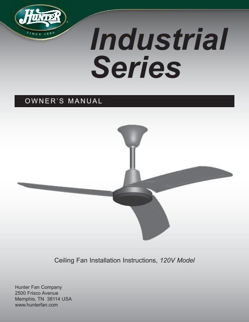
IndustrialSeriesOWNER’S <strong>MANUAL</strong>Ceiling <strong>Fan</strong> Installation Instructions, 120V Model<strong>Hunter</strong> <strong>Fan</strong> Company2500 Frisco AvenueMemphis, TN 38114 USAwww.hunterfan.com1 44200-01 02/06/2008
W a r n i n gTO REDUCE THE RISK OF ELECTRIC SHOCK OR INJURY, OBSERVE THE FOLLOWING:• Be cautious! Read all instructions and safety information before installing your new fan. Carefullyreview the assembly illustrations.• Use this unit only in the manner intended. If you have any questions, call your National Distributor.• All electrical work and installation must be in accordance with all applicable local electrical codes andstandards.• Before you begin installing the fan, switch power off at the switchboard and lock the switchboard to preventpower from being switched on accidentally during installation. When the switchboard cannot be locked,securely fasten a prominent warning device such as a danger tag to the switchboard.• When cutting or drilling into the wall or ceiling, be careful not to damage the electrical wiring and other hiddenutilities (such as cable and phone lines).• Make sure the installation site you choose allows the fan blades to rotate without any obstructions. Allow aminimum clearance of 2.1 metres from the floor to the tip of the blade.• To reduce the risk of fire, electric shock, or personal injury this fan must be mounted as marked and in an areasuitable for fan support. The mounting must support at least 16kg, using the screws provided.• Do not bend the blades during installation. Do not insert objects between rotating blades.• Attach the mounting bracket using only the hardware supplied.• Do not use this fan with any solid-state fan speed control device or variable speed control other than thedevice supplied with this fan. Using another controller, other than that supplied will void the manufacturerswarranty.• This fan is not intended for use by children or infirm persons without supervision.BEFORE BEGINNING, DISCONNECT THEPOWER SUPPLY AT THE SWITCHBOARD.FAILURE TO DO SO CAN RESULT INSERIOUS INJURY OR DEATH(16Kg/35 lb.min.)ENSURE THE STRUCTURE CANSUPPORT THE FULL WEIGHT OFTHE FAN (16 KG/35 LBS.)44200-01 02/06/20082
4Black White Ground / EarthSEE WIRING DIAGRAM ONPAGE 7These terminals arepre-wired at the factory.DO NOT REMOVE.5 6544200-01 02/06/2008
Line Out to<strong>Fan</strong>Main SupplyLineMainTerminal OutMainTerminal InGrey Green BrownC1C2Wiring Diagram for Wall Switch744200-01 02/06/2008
OPERATION<strong>Fan</strong> Speed ControlTo control the fan, set the fan speed control dial to the desired position as shown in Figure8. Positions are Off, High, Medium, and Low.OffHighLowMediumFigure 8<strong>Fan</strong> Directional ControlDuring cooler weather, place switch in the up position. During warmer weather, placeswitch in the down position.Cooler weatherposition.Warmer weatherposition.Figure 944200-01 02/06/20088