D-ATV DVB-S Transmitter Configuration File
D-ATV DVB-S Transmitter Configuration File
D-ATV DVB-S Transmitter Configuration File
- No tags were found...

Create successful ePaper yourself
Turn your PDF publications into a flip-book with our unique Google optimized e-Paper software.
3 The Old Teletext Encoder 113.1 Teletext section . . . . . . . . . . . . . . . . . . . . . . . . . . . . . . . . . . . . . . . . . . . . . . 113.1.1 Teletext Page Header . . . . . . . . . . . . . . . . . . . . . . . . . . . . . . . . . . . . . . 113.2 Teletext Page section . . . . . . . . . . . . . . . . . . . . . . . . . . . . . . . . . . . . . . . . . . . 123.2.1 Page Number . . . . . . . . . . . . . . . . . . . . . . . . . . . . . . . . . . . . . . . . . . . 123.2.2 Teletext Lines . . . . . . . . . . . . . . . . . . . . . . . . . . . . . . . . . . . . . . . . . . . 124 Sample <strong>Configuration</strong> 125 The New Teletext Encoder 125.1 C-Code . . . . . . . . . . . . . . . . . . . . . . . . . . . . . . . . . . . . . . . . . . . . . . . . . . 155.2 VM Built-In Library Functions . . . . . . . . . . . . . . . . . . . . . . . . . . . . . . . . . . . . . 155.2.1 C type sizes . . . . . . . . . . . . . . . . . . . . . . . . . . . . . . . . . . . . . . . . . . . . 155.2.2 C99 standard macros . . . . . . . . . . . . . . . . . . . . . . . . . . . . . . . . . . . . . . . 155.2.3 C99 standard types . . . . . . . . . . . . . . . . . . . . . . . . . . . . . . . . . . . . . . . . 155.2.4 C99 standard functions . . . . . . . . . . . . . . . . . . . . . . . . . . . . . . . . . . . . . 155.2.5 Event log functions . . . . . . . . . . . . . . . . . . . . . . . . . . . . . . . . . . . . . . . . 155.2.6 Time and Date functions . . . . . . . . . . . . . . . . . . . . . . . . . . . . . . . . . . . . 155.2.7 Parameters and Statistics functions . . . . . . . . . . . . . . . . . . . . . . . . . . . . . . . 165.2.8 Numeric to String conversion . . . . . . . . . . . . . . . . . . . . . . . . . . . . . . . . . . 165.2.9 TS1/TS2 table decoder . . . . . . . . . . . . . . . . . . . . . . . . . . . . . . . . . . . . . 165.2.10 Highlevel Teletext Enconding functions . . . . . . . . . . . . . . . . . . . . . . . . . . . . 175.2.11 Lowlevel Teletext Enconding functions . . . . . . . . . . . . . . . . . . . . . . . . . . . . . 176 Connecting the PC Parallel Port to a Transport Stream input 177 Acknowledgements 171 IntroductionThis document describes the file format and the semantics of the D-<strong>ATV</strong> <strong>Transmitter</strong> <strong>Configuration</strong> <strong>File</strong>. Thisconfiguration file is parsed by the fwtool utility and then written to the D-<strong>ATV</strong> transmitter onboard flashmemory through the serial interface.A typical invocation of fwtool looks as follows:fwtool -d /dev/com1 -c sample.conf -WThe -d Parameter indicates the serial port to which the D-<strong>ATV</strong> transmitter is connected. Port names arelisted in table 1.Port Windows Name Linux NameCOM1 /dev/com1 /dev/ttyS0COM2 /dev/com2 /dev/ttyS1Table 1: Port NamesThe following sections describe the configuration file format and the parameters. Parameters not documentedherein are considered experimental and may there not work or be removed anytime.1.1 TerminologyTransport Stream Data stream consisting of transport stream packets and containing any number of video,audio and/or data streams.Transport Stream Packet A fixed length 188 byte packet (4 bytes header, 184 bytes useable data) thatcarries the video, audio and other data. A PID indicates to the receiver to which stream the data belongsto.2
PID The Packet IDentifier (PID) is a 13 bit number (0–8191) that identifies the stream to which a TransportStream Packet belongs to. PID 8191 (hexadecimal 0x1fff) indicates a packet that does not contain usefuldata. It is used to fill transport streams when there is no useful data to transmit. PIDs 0–31 (0x00–0x1f)are reserved for system tables.FEC Forward Error Correction (FEC) adds redundant bits at the transmitter to enable the receiver to correcta few transmission errors.SI Tables System Information (SI) Tables are data structures present in every transport stream that enablethe receiver to find the programs. They are essentially the table of contents of the transport stream.2 The <strong>Configuration</strong> <strong>File</strong>2.1 General StructureFigure 1 shows the general structure of the configuration file. Lines starting with a hash mark # are commentlines and are not interpreted by fwtool. The board section groups parameters belonging to the D-<strong>ATV</strong> basebandboard. The modulator section groups modulation parameters. The transportstream parameters group parametersbelonging to the numbered transport stream input. Finally, the teletext section contains the parametersfor the teletext encoder and the still picture transmitter.# Sample D-<strong>ATV</strong> configuration fileboard {};modulator {};transportstream 1 {};transportstream 2 {};transportstream 3 {};transportstream 4 {};teletext {};Figure 1: General <strong>Configuration</strong> <strong>File</strong> StructureParameters are specified using the syntax parameter = value;. Number values may be decimal integers orhexadecimal integers with a 0x prefix. A k or M suffix multiplies the number with 1000 or 1000000 respectively.Text string values must be enclosed in double quotes "".Figure 2 shows the signal paths through the D-<strong>ATV</strong> transmitter. The baseband board interfaces to the datasources (such as MPEG2 encoders) through the transport stream interfaces. The transport stream (TS) inter-3
TS1ClockGenerationand SyncPID Filter128kByteFIFOtransportstream 1TS2ClockGenerationand SyncPID Filter128kByteFIFOtransportstream 2TS3ClockGenerationPID FilterModulatortransportstream 3TS4ClockGenerationPID Filtertransportstream 4TeletextEncoderStillPictureEncoderteletextFigure 2: Blockdiagramm4
faces are byte parallel interfaces consisting of eight data lines, a clock line, and several optional synchronisationlines. Table 2 shows the transport stream connector signal assignment.Signal Pins SignalV5.0 1 2 V5.0V5.0 3 4 V5.0SDA 5 6 XERROR or IRQ VCSCL 7 8 XRESETGND 9 10 GNDCK 11 12 SYVL 13 14 END6 15 16 D7D4 17 18 D5D2 19 20 D3D0 21 22 D1GND 23 24 GNDSDOUT 25 26 PLLTHRSCLK 27 28 SDINGND 29 30 GNDMCLKI 31 32 ASCLKRSTDA 33 34 BCLKTable 2: Transportstream-ConnectorTS1 and TS2 both have a FIFO in the signal path. The direction of the TS clock signal (CK) is thereforeconfigurable, that is, it can either be sourced by the D-<strong>ATV</strong> baseband board or the data source.TS3 and TS4, on the other hand, do not have a FIFO. The TS clock signal must therefore be driven by theD-<strong>ATV</strong> baseband board to avoid data loss. These ports are therefore mainly for use with the D-<strong>ATV</strong> MPEG2encoder.2.2 Board section2.2.1 Clock FrequencyThe clock parameter indicates the frequency of the crystal oscillator on the D-<strong>ATV</strong> baseband board. All timingsare derived from this crystal. The D-<strong>ATV</strong> board is normally shipped with a 60 MHz crystal, but for very lowbitrate applications, this crystal frequency may be reduced. The maximum is 62 MHz.Example:2.3 Modulator section2.3.1 FEC Rateclock = 60000000;This parameter specifies the inner Forward Error Correction code rate. It allows a trade-off between user bitrate and robustness of the modulation signal. Possible values are 1/2, 2/3, 3/4, 5/6 and 7/8.Example:2.3.2 <strong>Transmitter</strong> Frequencyfec = 5/6;The frequency parameter specifies the transmission frequency. It must lie either within the 23cm or the 13cmamateur radio band.Example:frequency = 1275M;5
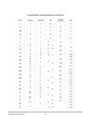
2.4.2 Active Clock EdgeThis parameter only has an effect if the port is in extclock mode. It specifies the active edge(s) of the TS clock(CK) signal. Valid values are falling, rising and both.Example:2.4.3 Clock Debounce Filterclock edge = rising;This parameter specifies the action of the clock debounce filter. Set the value to the largest N that satisfies thefollowing conditions: 1 ≤ N ≤ 4 and F T SCK < F clk2N .F T SCK Frequency of the Transport Stream Clock SignalN Clock Debounce Filter Parameter (see section 2.4.3)F clk Crystal Oscillator Frequency (see section 2.2.1)Example:2.4.4 Bitrateclock filter = 4;This parameter specifies the total useful bitrate sent into the port.Example:2.4.5 Video Input Selectionbitrate = 4500k;This parameter only has an effect in datvencoder mode. It specifies the characteristics of the video input signal.It consists of one or more keywords from the list below, separated by commas.d1 D1 resolutionhd1 HD1 resolutionsif SIF resolutionqsif QSIF resolutionntsc Input signal is NTSCpal Input signal is PALcomposite Use Composite portsvideo Use S-Video portExample:2.4.6 Video GOP <strong>Configuration</strong>video input = d1, pal, svideo;This parameter specifies the picture encoding sequence of the Encoder. The default mode provides good encodingefficiency at the expense of a higher encoding latency. Tuning this parameter, eg. by shortening the GOP size,latency may be reduced at the expense of the bitrate. This parameter should only be changed by experts whounderstand MPEG2 encoding.Example:2.4.7 Audio Encoder Bitratevideo gop = "IBBPBBPBBPBBPBB";This parameter only has an effect in datvencoder mode. It specifies the bitrate of the MPEG2 Layer 2 audioencoder. Valid bitrates depend on the encoding mode (subsection 2.4.8):7
Audio Encoding ModeBit Rate stereo joint stereo dual channel single channel√32k – – –√48k – – –√56k – – –√ √ √ √64k√80k – – –√ √ √ √96k√ √ √ √112k√ √ √ √128k√ √ √ √160k√ √ √ √192k√ √ √224k–√ √ √256k–√ √ √320k–√ √ √384k–Example:2.4.8 Audio Encoder Encoding Modeaudio bitrate = 384k;This parameter only has an effect in datvencoder mode. It specifies the encoding mode of the MPEG2 Layer2 audio encoder. The value must be one of the following keywords:stereoInput is a stereo signal.joint stereo Input is a stereo signal. Encoder shall use redundancies between both channels.dual channel Both channels are unrelated.single channel Only a single channel present.Example:2.4.9 Audio Encoder Sampling Rateaudio mode = joint stereo;This parameter only has an effect in datvencoder mode. It specifies the sampling rate of the MPEG2 Layer 2audio encoder. The value must be either 48000, 44100, or 32000.Example:2.4.10 Program Clock Reference (PCR) PIDaudio sample rate = 44100;This parameter sets the PID of the Program Clock Reference (PCR). It is normally set to the PID that containsthe video stream.Example:2.4.11 Video PIDThis parameter sets the PID of the video stream.Example:2.4.12 Audio PIDThis parameter sets the PID of the audio stream.Example:pcr pid = 0x20;video pid = 0x20;audio pid = 0x21;8
2.4.13 Program Map Table (PMT) PIDThis parameter sets the PID of the program map table (PMT). The PMT tells the receiver which PIDs belongto the TV channel and requires its own distinct PID.Example:2.4.14 Program Callsignpmt pid = 0x22;This parameter sets the callsign of the TV channel. The callsign is encoded into the SI tables, which allows thereceiver to display the channel identification.Example:2.4.15 Languagecallsign = "HB9JNX";This parameter identifies the language of the TV channel. It should be set to "eng" for english or to "DEU" forgerman.Example:2.4.16 PID filterlanguage = "eng";The PID filter allows the user to selectively reject PIDs on the corresponding TS input. Two strategies arepossible:1. pass all PIDs by default, list exceptions to reject2. reject all PIDs by default, list exceptions to passThe default is indicated by all or none, the exception terms are minus pid/mask and plus pid/mask. pidspecifies the PID number to match, and mask specifies which bits shall be compared.The resulting PID filter must reject the PID 8191 (0x1fff), the Null Packet PID.Examples:2.4.17 Tuner Modepidfilter = all minus 0x1ffe/0x1ffe;pidfilter = none plus 0x0020/0x1ffe;This parameter specifies whether a tuner is connected to the port. The following tuner modes exist:off No tuner connected to the portdfm DFM analog tuner connected to D-<strong>ATV</strong> MPEG2 encodermb86a15 Fujitsu <strong>DVB</strong>-S tuner connected directly to TS portExample:2.4.18 Tuner Frequencytuner mode = off;This parameter only has an effect if the tuner mode (section 2.4.17) is not set to off. It specifies the frequencyto which the tuner shall be tuned to.Example:tuner frequency = 1260M;9
2.4.19 Tuner FEC ModeThis parameter only has an effect if the tuner mode (section 2.4.17) is set to mb86a15. It specifies which innerFEC settings should be tried until a valid signal is found. Its value can either be auto or an inner FEC rate.Examples:2.4.20 Tuner Symbol Ratetuner fec = auto;tuner fec = 1/2;This parameter only has an effect if the tuner mode (section 2.4.17) is set to mb86a15. It specifies which symbolrate should be expected..Example:2.5 Teletext section2.5.1 Program Clock Reference (PCR) PIDtuner symrate = 3000k;This parameter sets the PID of the Program Clock Reference (PCR). It is normally set to the PID that containsthe video stream.Example:2.5.2 Video PIDpcr pid = 0x20;This parameter sets the PID of the video stream that contains the still picture.Example:2.5.3 Teletext PIDThis parameter sets the PID of the teletext stream.Example:2.5.4 Program Map Table (PMT) PIDvideo pid = 0x20;teletext pid = 0x21;This parameter sets the PID of the program map table (PMT). The PMT tells the receiver which PIDs belongto the TV channel and requires its own distinct PID.Example:2.5.5 Program Callsignpmt pid = 0x22;This parameter sets the callsign of the teletext/still picture channel. The callsign is encoded into the SI tables,which allows the receiver to display the channel identification.Example:2.5.6 Languagecallsign = "HB9JNX";This parameter identifies the language of the teletext/still picture channel. It should be set to "eng" for englishor to "DEU" for german.Example:language = "eng";10
2.5.7 Picture <strong>File</strong>This parameter specifies the file containing the picture that shall be transmitted on the still picture channel.This channel is intended to display eg. the logo of the operator. Note that this channel is not strictly <strong>DVB</strong>compliant, so there is no guarantee that every receiver is able to display the channel.The file must either be a JPEG file or contain an MPEG2 elementary stream. Note that software MPEG2encoders normally produce program stream files, which are incompatible. If the file contains a JPEG image(which must have 704×576 pixels), the mpeg2enc program from the mjpegtools package is used to convert theimage to an MPEG2 elementary stream. The mpeg2enc binary must be in the same directory as fwtool onWindows or in the /usr/bin directory under Linux.Example:2.5.8 VM Codepicture file = "mylogo.jpg";This parameter specifies the file containing the teletext encoder virtual machine bytecode. See section 5 foradditional information.Example:3 The Old Teletext Encodervm code = "teletext.o";The old teletext encoder is driven by a static table of teletext pages and their lines. It allows little dynamiccontent and no control over the encoding process itself. It will likely be removed in the future. Figure 3 showsthe configuration file instructions to encode an example teletext page.teletext {page header = "www.D-<strong>ATV</strong>.de \x92\x20\x08";page {number = 100;line 1 = "";line 2 = "\x01 www.D-<strong>ATV</strong>.de";line 3 = "";line 4 = "Digital Baseband:";line 5 = " Thomas Sailer, HB9JNX/AE4WA";line 6 = "";line 7 = "RF";line 8 = " Wolf-Henning Rech, DF9IC/N1EOW";line 9 = " Jens Geisler, DL8SDL";line 10 = "";line 11 = "Schematics, Boards &";line 12 = " Connections to Fujitsu";line 13 = " Stefan Reimann, DG8FAC";line 14 = "";line 15 = "\x03adacom e.V.";};};Figure 3: Old Teletext Encoder <strong>Configuration</strong> Lines3.1 Teletext section3.1.1 Teletext Page HeaderThis parameter sets the contents of the topmost teletext line that is displayed right of the page number.Example:page header = "www.D-<strong>ATV</strong>.de \x92\x20\x08";11
3.2 Teletext Page sectionThe teletext section may contain page { }; subsections, each specifying a single teletext page.3.2.1 Page NumberThis parameter specifies the teletext page number. Its value must be between 100 and 899 inclusive. Teletextdecoders start with page 100, so a page with number 100 should be present and display introductory material.Example:3.2.2 Teletext Linespage number = 100;These parameters specify the teletext page lines. The lines are numbered from 1 to 24 inclusive. Teletext linescan be up to 40 characters long. Shorter lines are padded with space characters. Nonprinting characters can beentered by a slash, followed by an “x”, and a two digit hexadecimal number that encodes the character code.For example, to enter character 1 (0x01), type “\x01”. Character codes 0–31 (0x00–0x1f) are used for ETSITeletext Attribute markup (eg. colours), and character codes 128–255 (0x80–0xff) are used to insert dynamicdata, such as packet counters. TODO: describe dynamic data insertion in more detail.Example:4 Sample <strong>Configuration</strong>line 2 = "\x01 www.D-<strong>ATV</strong>.de";Figure 4 shows a simple minimalistic configuration file. It assumes that there is one MPEG2 encoder connectedto TS1, and that TS2–TS4 are left unconnected.5 The New Teletext EncoderThe new teletext encoder allows full control over the encoding process and arbitrary dynamic content. It isdriven by a user bytecode program that is interpreted by a stack-based virtual machine.Bytecode teletext programs need not be written in the stack-based assembly language of the virtual machine(VM). They can be written in the C programming language and then compiled to bytecode.The following table shows the executables that constitute the bytecode development system:cpp C Preprocessorrcc C Compiler propervm VM Simulatorvmar Bytecode Archivervmas Bytecode Assemblervmdisass Bytecode Disassemblervmld Bytecode Linkeratv2txtvm Conversion utility from DG9MHZ <strong>ATV</strong> files to VM Teletext source codeAssuming the teletext encoder C code is contained in a file named teletext.c, the C code can be compiledand assembled into the object code file teletext.o using the following command:The object code file can be disassembled with:The object code file can be simulated with:vmas -c -o teletext.o teletext.cvmdisass teletext.ovm -c -1 -m teletext teletext.oFigure 5 shows an example source code of a teletext encoder.DG9MHZ <strong>ATV</strong> files [?] can be converted to VM teletext object code using:atv2txtvm -c -o teletext.o -i "D-<strong>ATV</strong>" -p 10 100 0000.<strong>ATV</strong> 101 0000.<strong>ATV</strong><strong>ATV</strong> files can be written by vtedit from [?].12
# Minimal D-<strong>ATV</strong> configuration fileboard {};clock = 60000000;modulator {fec = 2/3;frequency = 1275M;symbol rate = 3750k;network name = "HB9JNX";};transportstream 1 {mode = datvencoder;bitrate = 4500k;callsign = "HB9JNX";language = "eng";};transportstream 2 {mode = off;};transportstream 3 {mode = off;};transportstream 4 {mode = off;};teletext {callsign = "HB9JNX";language = "eng";picture file = "mylogo.jpg";vm code = "teletext.o";};Figure 4: Simple <strong>Configuration</strong> <strong>File</strong>13
* sample teletext encoder */#include "dvbs.h"static const char pg_header[] = TXT_ARG0 " www.D-<strong>ATV</strong>.de" TXT_ARG1;static const char *pg_100[] = {pg_header,NULL,TXTATTR_ALPHA_RED " www.D-<strong>ATV</strong>.de",NULL,"Digital Baseband:"," Thomas Sailer, HB9JNX/AE4WA",NULL,"RF"," Wolf-Henning Rech, DF9IC/N1EOW"," Jens Geisler, DL8SDL",NULL,"Schematics, Boards &"," Connections to Fujitsu"," Stefan Reimann, DG8FAC",NULL,TXTATTR_ALPHA_YELLOW "adacom e.V.",NULL,NULL,NULL,NULL,NULL,NULL,NULL,NULL,NULL};void teletext(void){char t[9];}for (;;) {timedec(t, NULL, gettime());teletext_encodepage(0, 24, 0x100, 0, 0, pg_100, "100", t);teletext_encodepage(0, 0, 0x1ff, 0, 0, pg_100, "100", t);}Figure 5: Example Teletext Encoder Source Code14
5.1 C-CodeThe header file dvbs.h contains prototypes for the built-in library functions.The VM starts the teletext encoder by calling the function teletext, with the prototype voidteletext(void).5.2 VM Built-In Library Functions5.2.1 C type sizesType Bitschar 8short 16int 32long 325.2.2 C99 standard macrosNULL, offsetof5.2.3 C99 standard typesptrdiff t, size t, int8 t, u int8 t, int16 t, u int16 t, int32 t, u int32 t5.2.4 C99 standard functionsmemcpy, memmove, strcpy, strncpy, strcat, strncat, memcmp, strcmp, strncmp, memchr, strchr, strcspn,strpbrk, strrchr, strspn, strstr, memset, strlen, exit5.2.5 Event log functionsvoid logreadinit(unsigned int *p); rewinds the event log to the oldest log message still in the circularbuffer. p is a pointer to an opaque cookie of type unsigned int.unsigned int logreadline(unsigned int *p, char *buf, unsigned int bufsz); reads the nextevent log message. p is a pointer to the opaque cookie initialized by logreadinit, buf a pointer to a bufferof suitable size, and bufsz the size of the buffer. logreadline returns the number of characters stored in thebuffer, which may not be zero terminated. A zero return value means that there are no more events in the eventlog buffer.5.2.6 Time and Date functionsstruct timeday modified julian date (number of days since november 17th 1858)msec millisecondssec seconds since midnight (UTC)valid if set, time and date have been set via the serial interface or DCF77struct timehmsh hoursm minutess secondsstruct dated daym months yearstruct time gettime(void); returns the current time.u int32 t getjiffies(void); returns a monotonically increasing number. It increments HZ times per second.struct date mjdtodate(u int16 t mjd); converts a modified julian date to a standard gregorian date.u int16 t datetomjd(u int16 t d, u int16 t m, u int16 t y); converts a standard gregorian date toa modified julian date.15
char *timedec(char *buf, struct timehms *hms, u int32 t tm); takes the number of seconds sincemidnight and converts it to hours, minutes and seconds and to a human readable string of the form 01:23:45.Both hms and buf may be NULL. The function returns a pointer to buf[0].5.2.7 Parameters and Statistics functionsu int16 t getadc(unsigned int n); returns the value of A/D converter n. n ranges from 0 to 3, and thereturn value of the 10 bit A/D converter is between 0 and 1023, corresponding to 0 and 5V at the input.u int32 t readcounter(unsigned int n); returns the value of counter n.n Value0 Local PCR (Program Clock Reference)1 Total packet count2 Mux-generated NULL packets3 Table/Teletext packets4 Transport Stream 1 packets5 Transport Stream 2 packets6 Transport Stream 3 packets7 Transport Stream 4 packets8–15 unusedu int8 t get inversion(void); returns the spectral inversion setting.u int8 t get fecmode(void); returns the FEC mode.return value FEC mode0 1/21 2/32 3/43 5/64 7/8u int32 t get frequency(void); returns the transmitter center frequency in kHz.u int8 t get ptt(void); returns whether the PTT is keyed.5.2.8 Numeric to String conversionflagsINTCONV SIGNnumber is signedINTCONV PLUSwrite an explicit + if a signed number is positiveINTCONV PADZERO pad buffer to the left with zerosINTCONV PADSPACE pad buffer to the left with spacesINTCONV LOWERCASE use lower case hexadecimal characterschar *int2hex(char *buf, u int16 t len, u int32 t val, u int16 t flags); converts val to a decimalstring, which is stored into the buffer buf. Up to len characters are stored, and thus buf must be at leastlen + 1 characters big. The function returns a pointer to the beginning of the number string, which is anywherewithin buf, but not necessarily at the beginning.char *int2dec(char *buf, u int16 t len, u int32 t val, u int16 t flags); converts val to a hexadecimalstring, which is stored into the buffer buf. Up to len characters are stored, and thus buf must be atleast len + 1 characters big. The function returns a pointer to the beginning of the number string, which isanywhere within buf, but not necessarily at the beginning.5.2.9 TS1/TS2 table decoderThe TS1/TS2 table decoder tries to extract data from the System Information tables received on transportstream ports 1 and 2.struct portcaptureevent idincremented, whenever service descriptor table information is updatedtransport stream id Transport Stream IDnit pidPID where the Network Information Table is transmittedservice idService IDnetwork idNetwork IDservice provider name Service Provider Nameservice nameService Name16
For more detailed information about <strong>DVB</strong> System Information (SI) tables, see [1].struct portcapture getcapture(unsigned int port); returns SI table data for transport stream portport.port0 TS11 TS2Transport Stream5.2.10 Highlevel Teletext Enconding functionsvoid teletext encodepage(u int16 t startline, u int16 t endline, u int16 t pagenr, u int16 tsubnr, u int32 t flags, const char **lines, ...); encodes multiple teletext lines, from line numberstartline to endline. startline is usually 0, and endline 24. pagenr specifies the page number, and shouldbe between 0x100 and 0x8ff. Page numbers containing the hexadecimal characters A–F are not directlyaccessible by the receiver. subnr specifies the subpage number (normally 0). flags can be zero or multipleTXTPAGECTRL macros ored. TXTPAGECTRL are described in detail in [2, 9.3.1.3, p. 27]. lines contains a pointerto an array of endline-startline+1 strings. Each string specifies the contents of the corresponding line. ANULL pointer suppresses the encoding of the corresponding line. Teletext lines may contain TXTATTR macros(see [2, 12.2, p. 76–80]) or TXT ARGn to reference one of the optional arguments. ... can contain up to 64pointers to strings that can be referenced using the TXT ARGn macro.5.2.11 Lowlevel Teletext Enconding functionsvoid teletext oddparity(u int8 t *buf, const u int8 t *src, unsigned int len); encodes a databuffer pointed to by src of size len using the teletext odd parity code and stores it into buf.void teletext hamming84(u int8 t *buf, const u int8 t *src, unsigned int nibblelen); encodesa data buffer pointed to by src containing len nibbles using the teletext 8/4 hamming code and storesit into buf. It first encodes the low nibble of src[0], then the high nibble of src[0], then the low nibble ofsrc[1], and so on.void teletext hamming2418(u int8 t *buf, const u int8 t *src, unsigned int len); encodes adata buffer pointed to by src containing len triples using the teletext 24/18 hamming code and stores itinto buf. The src[0] contains the low 6 bits, src[1] the middle 6 bits, and src[2] the high 6 bits.u int8 t *teletext currentline(void); returns a pointer to the current line buffer. The line buffer sizeis 42 bytes, and it contains a complete teletext line without the clock run-in and the framing code [2, 7.1, p.17ff].u int8 t *teletext waitline(void); transmits the current line and returns a pointer to the line bufferof the next line.6 Connecting the PC Parallel Port to a Transport Stream inputThe PC Parallel port may be used as a simple means to inject low rate data into the transport stream. Up toabout 2MBit/s are possible. Table 3 shows how the parallel port signals should be wired to TS1 or TS2. Theinput port must be set to extclock mode, and thett clock filter should be set to 4, the maximum.7 AcknowledgementsThe Microcontroller Firmware contains uIP, Copyright (c) 2001, Adam Dunkels.The VM bytecode C compiler is based on LCC, written by Chris Fraser and David Hanson. LCC sourcescan be obtained free of charge from the LCC homepage [?].References[1] ETSI EN 300 468 V1.4.1 European Standard (Telecommunications series) Digital Video Broadcasting(<strong>DVB</strong>); Specification for Service Information (SI) in <strong>DVB</strong> systems, 07 2000.[2] European Telecommunications Standards Institute (ETSI). ETS 300 706: Enhanced Teletext Specification,May 1997.17
Pin Parport-Signal TS-Signal1 nStrobe CK2 D0 D03 D1 D14 D2 D25 D3 D36 D4 D47 D5 D58 D6 D69 D7 D710 nAck nStrobe11 Busy ASCLK12 PError SCLK13 Select SDIN14 nAutoFd SY15 nFault XRESET16 nInit VL17 nSelectIn EN18. . . 25 GND GNDTable 3: Parallel Port Connector Wiring18