Cryogenic Controls PDF (CAVMC-0514 - Cash Valve
Cryogenic Controls PDF (CAVMC-0514 - Cash Valve
Cryogenic Controls PDF (CAVMC-0514 - Cash Valve

Create successful ePaper yourself
Turn your PDF publications into a flip-book with our unique Google optimized e-Paper software.
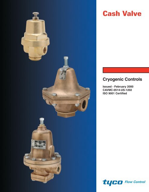
<strong>Cash</strong> <strong>Valve</strong><br />
<strong>Cryogenic</strong> <strong>Controls</strong><br />
Issued - February 2000<br />
<strong>CAVMC</strong>-<strong>0514</strong>-US-1202<br />
ISO 9001 Certified<br />
Flow Control
<strong>Cryogenic</strong> <strong>Controls</strong>/Pressure Reducing <strong>Valve</strong>s/Pressure Build-Up Regulators<br />
<strong>Cryogenic</strong>s – the science of materials at<br />
extremely low temperatures – has become more<br />
and more important to industry. One important<br />
aspect of this field is the liquification of normally<br />
gaseous elements, including the following,<br />
which are widely used throughout industry:<br />
OXYGEN – Used extensively in BOF furnaces<br />
in the steel industry, for metal cutting, as a<br />
rocket fuel and in medicine.<br />
ACETYLENE – Widely used in welding.<br />
NITROGEN – Used in refrigeration systems, for<br />
metal degassing, in aerosol packaging and in<br />
cryogenic surgery.<br />
HYDROGEN – Used as a rocket propellant and<br />
in the production of several metals.<br />
ARGON – Widely used in incandescent lamps<br />
and fluorescent tubes.<br />
HELIUM – Used for arc welding, in the<br />
manufacture of electron tubes and in cryogenic<br />
research.<br />
CARBON DIOXIDE – Used in refrigeration, to<br />
make aerosol tanks and in fire fighting.<br />
Other cryogenic fluids include liquefied natural<br />
gas, fluorine, krypton, neon, methane and<br />
ethane.<br />
Industrial gases were previously stored in large,<br />
bulky, pressurized metal containers, but now<br />
these gases are stored and shipped in their<br />
liquid state in cryogenic containers called<br />
“Dewars” or converters. Dewars are jacketed<br />
storage vessels that safely maintain liquids at<br />
cryogenic temperatures. The main advantage of<br />
cryogenic containers is a substantial saving of<br />
storage space as demonstrated by the following<br />
example: 162.8 standard cubic feet [4.61 cubic<br />
Construction<br />
Brass forged body and spring chamber; bronze trim and<br />
diaphragms; Teflon® seat disc and diaphragm gasket;<br />
stainless steel pressure spring. All parts are commercially<br />
cleaned for cryogenic service.<br />
NOTE: Also available in stainless steel and special<br />
construction for Hi-Purity service. Contact your sales<br />
representative.<br />
Temperature Rating<br />
+150°F to -320°F [339°K to 78°K]<br />
Maximum Initial Pressure<br />
600 psi [42.18 kg/sq cm]<br />
2<br />
meters] of gas at ambient temperature, when<br />
subjected to a pressure of 2,400 psi [168.72<br />
kg/sq cm] in a pressurized container, will have a<br />
measured volume of one cubic foot [0.028 cubic<br />
meter]; however, 696 standard cubic feet [19.1<br />
cubic meters] of the same gas can be stored in<br />
its liquid state at cryogenic temperatures in a<br />
Dewar with the same measured volume of one<br />
cubic foot [0.028 cubic meter]. This means that,<br />
under cryogenic conditions, the Dewar can<br />
accommodate 4.28 times the quantity of a<br />
normally gaseous element as a pressurized gas<br />
cylinder.<br />
<strong>Cryogenic</strong> converters are available in a variety<br />
of sizes and shapes and can be either<br />
stationary or installed on over-the-road transport<br />
trucks. They are generally used for liquids with a<br />
boiling point anywhere from -109.3°F [194.7°K]<br />
for carbon dioxide to -452°F [4.3°K] for helium.<br />
Dewars are supplied with inbuilt controls that<br />
allow the material to be drawn as either liquid or<br />
gas. The schematic located on the back cover<br />
illustrates a typical cryogenic container and<br />
controls. While there are many different versions<br />
of this basic system, the components remain<br />
fairly constant. <strong>Cash</strong> <strong>Valve</strong> manufactures a<br />
variety of controls for cryogenic systems,<br />
including liquid and gas line-pressure build-up<br />
regulators, economizer (heat leak) back<br />
pressure valves, temperature safety valves,<br />
combination valves, shut-off valves and finalline/service-line<br />
regulators. This data sheet<br />
presents a detailed description of <strong>Cash</strong> <strong>Valve</strong>’s<br />
line of cryogenic-service valves.<br />
The Pressure Build-up Circuit<br />
The purpose of the build-up circuit is to maintain<br />
in the converter a pressure approximately 25 psi<br />
[1.76 kg/sq cm] above that required to drive the<br />
liquid to the final vaporizer and to maintain a<br />
pressure differential of approximately 25 psi<br />
[1.76 kg/sq cm] or higher across the service line<br />
regulator. To do this, liquid is drawn into the<br />
pressure build-up coil, where it is warmed by<br />
ambient air and vaporized. The gas then passes<br />
1 the pressure build-up regulator and into the<br />
top of the tank, where it begins to build up<br />
pressure because expansion is limited by the<br />
fixed volume. When this pressure reaches the<br />
set point of the pressure build-up regulator, the<br />
regulator shuts off, stopping vaporization and<br />
pressure build-up. As liquid is forced from the<br />
tank to the final vaporizer, pressure in the tank<br />
begins to drop and the pressure build-up<br />
regulator again begins operating.<br />
The pressure build-up regulator may be located<br />
in the liquid line before the pressure build-up<br />
coil. Since it is now used for liquid rather than<br />
gas service, the regulator may have a smaller<br />
orifice or be a smaller-sized valve. The operation<br />
of a liquid pressure build-up regulator is the<br />
same as that of a gas regulator with the<br />
exception that it regulates the liquid flow before<br />
the pressure build-up coil rather than the gas<br />
flow after the coil. When pressure in the tank<br />
drops, the liquid pressure build-up regulator<br />
opens, allowing liquid to flow through the<br />
pressure build-up coil and vaporize.<br />
<strong>Cash</strong> <strong>Valve</strong> manufactures pressure build-up<br />
regulators for most cryogenic system<br />
applications. The Type A-32 is a small (1/4",<br />
8 mm) pressure build-up valve; the larger<br />
Type B, Type G-60 and Type E-55 can be used<br />
for either liquid or gas. The Type B is available<br />
in sizes from 1/4" to 2" [8 mm to 50 mm], the<br />
G-60 from 1/4" to 11/2" [8 mm toh 40 mm] and the<br />
Type E-55 from 11/4" to 2" [32 mm to 50 mm].<br />
A-32 Pressure Reducing or Pressure Build-Up Service ____________________________<br />
Reduced Pressure Ranges<br />
Maximum Working<br />
Spring Pressure<br />
Number psi [kg/sq cm]<br />
4764 2-25 [0.14-1.76]<br />
4765 15-65 [1.05-4.57]<br />
12447 40-100 [2.81-7.03]<br />
12108 50-150 [3.52-10.55]<br />
7337 75-175 [5.27-12.30]<br />
10661 100-250 [7.03-17.58]<br />
— 200-400 [14.06-28.12]<br />
— 300-600 [21.09-42.18]<br />
Dimensions<br />
Dimensions Shipping<br />
Size A B C Weight<br />
inches [mm] inches [mm] inches [mm] inches [mm] lbs (kgs)<br />
1/4 [8] 21/4 [57.15] 33/16 [80.96] 5/8 [15.88] 11/8 (0.51)<br />
3/8 [10] 21/4 [57.15] 33/16 [80.96] 5/8 [15.88] 11/8 (0.51)<br />
A<br />
B<br />
C<br />
<strong>CAVMC</strong>-<strong>0514</strong>
Pressure Reducing <strong>Valve</strong>s/Pressure Build-Up and Final Line Regulators<br />
A-36 Pressure Reducing or Pressure Build-Up Service ____________________________<br />
Construction<br />
Brass forged body and bronze spring chamber; bronze trim and<br />
diaphragms; Teflon® seat disc and gaskets; stainless steel pressure<br />
spring. All parts are commercially cleaned for cryogenic service.<br />
NOTE: Also available in stainless steel and special construction<br />
for Hi-Purity service. Contact your sales representative.<br />
Reduced Pressure Ranges<br />
<strong>Valve</strong> Spring Maximum Working Ranges<br />
Number Number psi [kg/sq cm]<br />
Dimensions<br />
8238 10-30 [0.70-2.11]<br />
8239 20-50 [1.41-3.52]<br />
11520 8240 40-80 [2.81-5.62]<br />
8241 75-150 [5.27-10.55]<br />
8242 100-250 [7.03-17.58]<br />
High Pressure Construction Only<br />
15299 14272 200-400 14.06-28.12<br />
Temperature Rating<br />
+150°F to -320°F [339°K to 78°K]<br />
Maximum Initial Pressure<br />
600 psi [42.18 kg/sq cm]<br />
Dimensions Shipping<br />
<strong>Valve</strong> Size A B C Weight<br />
Number inches [mm] inches [mm] inches [mm] inches [mm] lbs (kgs)<br />
11520 3/8 [10] 2 7/16 [61.91] 4 1/2 [114.30] 1 [25.40] 2 1/2 (1.13)<br />
15299 3/8 [10] 2 7/16 [61.91] 4 1/2 [114.30] 1 [25.40] 2 1/2 (1.13)<br />
A-401 Pressure Reducing or Pressure Build-Up Service __________________________<br />
Construction<br />
Bonze cast body and bronze spring chamber; bronze trim and<br />
Neoprene/Nylon diaphragms; Viton® seat disc and gaskets;<br />
stainless steel pressure spring. All parts are commercially<br />
cleaned for cryogenic service.<br />
Reduced Pressure Ranges<br />
<strong>Valve</strong> Spring Maximum Working Ranges<br />
Number psi [kg/sq cm]<br />
Dimensions<br />
8239 20 to 60 [1.41 to 4.22]<br />
8240 40 to 80 [2.81 to 5.62]<br />
21999 8241 75 to 125 [5.27 to 8.79]<br />
8242 100 to 250 [7.03 to 17.58]<br />
14272 200 to 400 [14.06 to 28.12]<br />
High Pressure Construction Only<br />
21971 14272 300 to 600 [21.09 to 42.18]<br />
Temperature Rating<br />
+150°F to -320°F [339°K to 78°K]<br />
Maximum Initial Pressure<br />
600 psi [42.18 kg/sq cm]<br />
Dimensions Shipping<br />
Size A B C Weight<br />
inches [mm] inches [mm] inches [mm] inches [mm] lbs (kgs)<br />
1/2 [15] 4 [101.6] 4.64 [117.80] 1.95 [49.6] 41/2 (1.68)<br />
<strong>CAVMC</strong>-<strong>0514</strong><br />
A<br />
A<br />
B<br />
C<br />
B<br />
C<br />
3
Pressure Reducing <strong>Valve</strong>s/Pressure Build-Up Regulators<br />
B Pressure Reducing or Pressure Build-Up Service __________________________________<br />
Construction<br />
Bronze body, spring chamber, trim and<br />
diaphragms; Teflon® seat and diaphragm gasket;<br />
stainless steel pressure spring; stainless steel<br />
bolts and nuts; Teflon® bottom-plug gasket;<br />
Monel® strainer screen. All parts are<br />
commercially cleaned for cryogenic service.<br />
Also available with BSP threads.<br />
Temperature Rating<br />
+150°F to -320°F [339°K to 78°K]<br />
Maximum Initial Pressure<br />
400 psi [28.12 kg/sq cm]<br />
Note: Type B95 available in stainless steel<br />
construction 1/2" thru 1" size.<br />
4<br />
B<br />
C<br />
A<br />
Reduced Pressure Ranges<br />
<strong>Valve</strong> Size Spring Maximum Working Ranges<br />
Inches [mm] Number psi [kg/sq cm]<br />
4765 10-30 [0.70-2.11]<br />
1/4 [8]<br />
7337<br />
8741<br />
25-100<br />
50-200<br />
[1.76-7.03]<br />
[3.52-14.06]<br />
10661 100-250 [7.03-17.58]<br />
11143 10-50 [0.70-3.52]<br />
3/8 [10] 8691 40-150 [2.81-10.55]<br />
14301 100-250 [7.03-17.58]<br />
11143 10-30 [0.70-2.11]<br />
10016 20-75 [1.41-5.27]<br />
1/2 [15] 10017 25-125 [1.76-8.79]<br />
10018 100-200 [7.03-14.06]<br />
10019 150-250 [10.55-17.58]<br />
11143 10-30 [0.70-2.11]<br />
10016 20-70 [1.41-4.92]<br />
3/4 [20]<br />
10017<br />
10018<br />
30-100<br />
50-150<br />
[2.11-7.03]<br />
[3.52-10.55]<br />
10019 100-225 [7.03-15.82]<br />
9983 150-250 [10.55-17.58]<br />
8484 10-35 [0.70-2.46]<br />
1 [25]<br />
8485<br />
8486<br />
20-60<br />
50-100<br />
[1.41-4.22]<br />
[2.52-7.03]<br />
8487 100-250 [7.03-17.58]<br />
8484 10-30 [0.70-2.11]<br />
1<br />
8485 20-40 [1.41-2.81]<br />
1/4 [32]<br />
8486 35-80 [2.46-5.62]<br />
8487 75-150 [3.52-10.55]<br />
8484 10-30 [0.70-2.11]<br />
11/2 [40]<br />
8485<br />
8486<br />
20-40<br />
35-80<br />
[1.41-2.81]<br />
[2.46-5.62]<br />
8487 75-150 [3.52-10.55]<br />
6301 5-20 [0.35-1.41]<br />
2 [50] 8773 10-50 [0.70-3.52]<br />
8490 20-100 [1.41-7.03]<br />
Dimensions<br />
Dimensions Shipping<br />
<strong>Valve</strong> Size A B C Weight<br />
Number inches [mm] inches [mm] inches [mm] inches [mm] lbs (kgs)<br />
12315 1/4 [8] 3 [76.2] 2 7/8 [73.03] 1 3/4 [44.45] 3 (1.35)<br />
12316 3/8 [10] 3 7/8 [98.43] 4 1/8 [104.78] 1 3/4 [44.45] 5 1/2 (2.47)<br />
12290 1/2 [15] 4 1/2 [114.3] 4 1/2 [114.3] 2 1/8 [53.98] 8 (3.6)<br />
12300 3/4 [20] 5 1/8 [130.18] 4 5/8 [117.48] 2 1/8 [53.98] 10 (4.5)<br />
12319 1 [25] 5 7/8 [149.23] 5 3/8 [136.53] 2 5/8 [66.68] 16 (7.2)<br />
12320 1 1/4 [32] 6 3/4 [171.45] 6 1/8 [155.58] 2 5/8 [66.68] 20 (9.0)<br />
12321 1 1/2 [40] 6 3/4 [171.45] 6 1/8 [155.58] 3 1/4 [82.55] 20 (9.0)<br />
8580 2 [50] 9 1/4 [234.95] 8 1/2 [215.9] 3 1/2 [88.90] 37 (16.65)<br />
<strong>CAVMC</strong>-<strong>0514</strong>
Reduced Pressure Ranges<br />
<strong>CAVMC</strong>-<strong>0514</strong><br />
Pressure Reducing <strong>Valve</strong>s/Pressure Build-Up Regulators<br />
G-60 Pressure Reducing or Pressure Build-Up Service ____________________________<br />
<strong>Valve</strong> Size Spring Maximum Working Ranges<br />
Inches [mm] Number psi [kg/sq cm]<br />
1/4 & 3/8 [8 & 10]<br />
8483 5-30 [0.35-2.11]<br />
8484 15-65 [1.05-4.57]<br />
8485 30-110 [2.11-7.73]<br />
8486 75-200 [5.27-14.06]<br />
10019* 100-400* [7.03-28.12*]<br />
8487* 100-600* [7.03-42.18*]<br />
8488 0-7 [0-0.49]<br />
8489 5-70 [0.35-4.92]<br />
1/2 [15] 8490 50-150 [3.52-10.55]<br />
3/4 [20]<br />
7806 50-250 [3.52-17.58]<br />
7806* 100-600* [7.03-42.18]<br />
8493 0-10 [0-0.70]<br />
8494 5-75 [0.35-5.27]<br />
8495 50-200 [3.52-14.06]<br />
8495* 100-600* [7.03-42.18]<br />
10672 10-50 [0.70-3.52]<br />
1 [25] 10751 50-200 [3.52-14.06]<br />
1 1/4 & 1 1/2 [32 & 40]<br />
10751* 100-600* [7.03-42.18]<br />
13577 5-15 [0.35-1.05]<br />
13579 10-50 [0.70-3.52]<br />
13581 30-75 [2.11-5.27]<br />
13583 50-120 [3.52-8.44]<br />
13575 75-150 [5.27-10.55]<br />
13575* 100-400* [7.03-28.12]<br />
* Note: Higher ranges are attained by modifying standard valve and/or using a different pressure<br />
spring. Contact your sales representative.<br />
Dimensions<br />
Dimensions Shipping<br />
Size A B C Weight<br />
inches[mm] inches[mm] inches [mm] inches [mm] lbs (kgs)<br />
1/4 [8] 4 [101.60] 65/8 [168.28] 23/16 [55.55] 9 (4.05)<br />
3/8 [10] 4 [101.60] 65/8 [168.28] 23/16 [55.55] 9 (4.05)<br />
1/2 [15] 43/4 [120.65] 75/8 [193.68] 25/16 [58.72] 16 (7.20)<br />
3/4 [20] 55/8 [142.88] 10 [254.00] 25/8 [66.68] 24 (10.80)<br />
1 [25] 61/2 [165.10] 103/4 [273.05] 27/8 [73.03] 35 (15.75)<br />
11/4 [32] 8 [203.20] 125/16 [312.74] 39/16 [90.49] 63 (28.35)<br />
11/2 [40] 8 [203.20] 125/16 [312.74] 39/16 [90.49] 63 (28.35)<br />
Construction<br />
Threaded ends; bronze body, spring chamber,<br />
diaphragms and trim; stainless steel pressure<br />
spring and body seat; Teflon® seat and gaskets;<br />
stainless steel bolts. Closing cap over screw<br />
provided. Also available with all system<br />
exposed internal parts in stainless steel. All<br />
parts are commercially cleaned for cryogenic<br />
service. Also available with BSP threads.<br />
NOTE: Also available in stainless steel and<br />
special construction for Hi-Purity service.<br />
Contact your sales representative.<br />
Temperature Rating<br />
+150°F to -320°F [339°K to 78°K]<br />
Maximum Initial Pressure<br />
600 psi [42.18 kg/sq cm]<br />
A<br />
B<br />
C<br />
5
Pressure Reducing/Pressure Build-up <strong>Valve</strong>s<br />
E-55 Pressure Reducing or Pressure Build-Up Service ____________________________<br />
6<br />
B<br />
C<br />
A<br />
Construction<br />
Bronze body, spring chamber, trim; stainless<br />
steel body seat and pressure spring; Teflon®<br />
seat, O-rings, and bottom plug gasket; Monel®<br />
diaphragms and strainer screen; stainless<br />
steel bolts. All parts are commercially cleaned<br />
for cryogenic service. Also available with BSP<br />
threads.<br />
Temperature Rating<br />
+150°F to -320°F [339°K to 78°K]<br />
Maximum Initial Pressure<br />
400 psi [28.12 kg/sq cm]<br />
Reduced Pressure Ranges<br />
Spring Maximum Working Ranges<br />
<strong>Valve</strong> Size Number psi [kg/sq cm]<br />
8773 20-70 [1.41-4.92]<br />
All Sizes 12913 50-150 [3.52-10.55]<br />
8774 75-300 [7.03-17.58]<br />
Dimensions<br />
Dimensions Shipping<br />
<strong>Valve</strong> Size A B C Weight<br />
Number inches [mm] inches [mm] inches [mm] inches [mm] lbs (kgs)<br />
11980 11/4 [32] 55/8 [142.88] 77/8 [200.0] 31/4 [82.55] 17 (7.65)<br />
11981 11/2 [40] 55/8 [142.88] 77/8 [200.0] 31/4 [82.55] 17 (7.65)<br />
11982 2 [50] 53/4 [146.05] 81/2 [215.9] 27/8 [73.03] 17 (7.65)<br />
<strong>CAVMC</strong>-<strong>0514</strong>
<strong>CAVMC</strong>-<strong>0514</strong><br />
Back Pressure/Economizer <strong>Valve</strong>s<br />
The Economizer Circuit ____________________________________________________________<br />
The Economizer Back Pressure Regulator is<br />
set from 10 to 25 psi (.70 to 1.76 kg/sq cm)<br />
above the set pressure of the pressure buildup<br />
regulator. When no gas is being used and<br />
heat leakage in the tank causes a gas<br />
pressure build-up, the excess pressure is<br />
Construction<br />
Threaded ends; 2-way, side inlet-side outlet;<br />
2-way, side inlet-bottom outlet; 3-way, 2 side<br />
inlets-bottom outlet; forged bronze body;<br />
bronze diaphragms; stainless steel seat disc,<br />
seat ring and pressure spring; Teflon®<br />
diaphragm gasket. All parts commercially<br />
cleaned for cryogenic service.<br />
NOTE: Also available in stainless steel<br />
and special construction for Hi-Purity<br />
service. Contact your sales<br />
representative.<br />
bypassed into the final vaporizer line to<br />
conserve gas rather than allow the safety valve<br />
in the pressure build-up circuit to relieve the<br />
excess gas into the atmosphere.<br />
<strong>Cash</strong> <strong>Valve</strong> offers five types of back pressure<br />
valves for this circuit: the Type FRM, low flows,<br />
Temperature Rating<br />
+150°F to -320°F [339°K to 78°K]<br />
Maximum Set Pressure<br />
600 psi [42.18 kg/sq cm]<br />
max. 600 psi (42.18 kg/sq cm), the FRM-2,<br />
medium flows, max. 250 psi (17.58 kg/sq cm),<br />
the FRM-2 High Pressure, medium flows, max.<br />
400 psi (28.12 kg/sq cm), the FR, large flows,<br />
max. 400 psi (28.12 kg/sq cm), and the FR-6,<br />
max. 600 psi (42.18 kg/sq cm).<br />
FRM Back Pressure or Economizer Service ______________________________________<br />
Pressure Ranges<br />
Spring Maximum Working Ranges<br />
Number psi [kg/sq cm]<br />
4764 2-25 [0.14-1.76]<br />
4765 15-65 [1.05-4.57]<br />
12447 40-100 [2.81-7.03]<br />
7337 75-175 [5.27-12.30]<br />
10661 100-250 [7.03-17.58]<br />
— 200-400 [14.06-28.12]<br />
— 300-600 [21.09-42.18]<br />
Dimensions<br />
<strong>Valve</strong> Size<br />
Shipping<br />
Weight<br />
Number* Description inches [mm] lbs (kgs)<br />
11224 Side inlet, Side outlet 1/4 [8] 11/8 (0.51)<br />
11225 Side inlet, Side outlet 3/8 [10] 11/8 (0.51)<br />
7335 Side inlet, Bottom outlet 1/4 [8] 11/8 (0.51)<br />
9172 Side inlet, Bottom outlet 3/8 [10] 11/8 (0.51)<br />
8250 2 Side inlets, Bottom outlet 1/4 [8] 11/8 (0.51)<br />
* Use valve numbers for pressures to 175 psi only. Consult factory for other numbers.<br />
33/8"<br />
[85.73 mm]<br />
1/2"<br />
[12.7 mm]<br />
21/4"<br />
[57.15 mm]<br />
7
Back Pressure/Economizer <strong>Valve</strong>s<br />
FRM-2, FRM-2 (HP) Back Pressure or Economizer Service ______________<br />
8<br />
C<br />
B<br />
A<br />
Construction<br />
Threaded ends; 2-way, side inlet-side outlet;<br />
2-way, side inlet-bottom outlet; 3-way, 2 side<br />
inlets-bottom outlet; forged bronze body; cast<br />
bronze spring chamber; stainless steel seat<br />
disc, seat ring and pressure spring; bronze<br />
diaphragms; Teflon® diaphragm gasket. All<br />
parts commercially cleaned for cryogenic<br />
service.<br />
Pressure Ranges<br />
Spring Maximum Working Ranges<br />
Number Size psi [kg/sq cm]<br />
FRM-2<br />
8238 All Sizes 0-30 [0-2.11]<br />
8239 All Sizes 20-50 [1.41-3.52]<br />
8240 All Sizes 40-80 [2.81-5.62]<br />
8241 All Sizes 75-150 [5.27-10.55]<br />
8242 All Sizes 100-275 [7.03-19.34]<br />
FRM-2HP<br />
NOTE: FRM-2 available in stainless steel<br />
and special construction for Hi-Purity<br />
service. Contact your sales<br />
representative.<br />
Temperature Rating<br />
+150°F to -320°F [339°K to 78°K]<br />
Maximum Set Pressure<br />
FRM-2: 250 psi [17.58 kg/sq cm]<br />
FRM-2HP: 400 psi [28.12 kg/sq cm]<br />
14272 All Sizes 200-400 [14.06-28.12]<br />
Dimensions<br />
Dimensions Shipping<br />
<strong>Valve</strong> Size A B C Weight<br />
Number* Description inches [mm] inches [mm]<br />
FRM-2<br />
inches [mm] inches [mm] lbs (kgs)<br />
12790 Side inlet, Side outlet 1/4 [8] 211/16 [68.26] 41/2 [114.3] 3/4 [19.05] 21/2 (1.13)<br />
11831 Side inlet, Side outlet 3/8 [10] 211/16 [68.26] 41/2 [114.3] 3/4 [19.05] 21/2 (1.13)<br />
10673 Side inlet, Side outlet 1/2 [15] 27/8 [73.03] 41/2 [114.3] 11/8 [28.58] 31/2 (1.58)<br />
8702 Side inlet, Bottom outlet 1/4 [8] 211/16 [68.26] 41/2 [114.3] 3/4 [19.05 21/2 (1.13)<br />
8703 Side inlet, Bottom outlet 3/8 [10] 211/16 [68.26] 41/2 [114.3] 3/4 [19.05] 21/2 (1.13)<br />
8704 Side inlet, Bottom outlet 1/2 [15] 27/8 [73.03] 41/2 [114.3] 11/8 [28.58] 31/2 (1.58)<br />
12605 2 Side inlets, Bottom outlet 1/4 [8] 211/16 [68.26] 41/2 [114.3] 3/4 19.05] 21/2 (1.13)<br />
8245 2 Side inlets, Bottom outlet 3/8 [10] 211/16 [68.26] 41/2 [114.3] 3/4 [19.05] 21/2 (1.13)<br />
12070 2 Side inlets, Bottom outlet 1/2 [15] 27/8 [73.03] 41/2 [114.3] 11/8 [28.58] 31/2 (1.58)<br />
FRM-2HP<br />
14275 Side inlet, Side outlet 1/4 [8] 211/16 [68.26] 41/2 [114.3] 25/32 [19.84] 21/2 (1.13)<br />
15555 Side inlet, Bottom outlet 1/4 [8] 211/16 [68.26] 41/2 [114.3] 25/32 [19.84] 21/2 (1.13)<br />
15392 Side inlet, Side outlet 3/8 [10] 211/16 [68.26] 41/2 [114.3] 25/32 [19.84] 21/2 (1.13)<br />
16719 Side inlet, Bottom outlet 3/8 [10] 211/16 [68.26] 41/2 [114.3] 25/32 [19.84] 21/2 (1.13)<br />
15895 Side inlet, Side outlet 1/2 [15] 211/16 [68.26] 41/2 [114.3] 11/8 [28.585] 31/2 (1.58)<br />
15425 Side inlet, Bottom outlet 1/2 [15] 211/16 [68.26] 41/2 [114.3] 25/32 [19.84] 31/2 (1.58)<br />
<strong>CAVMC</strong>-<strong>0514</strong>
<strong>CAVMC</strong>-<strong>0514</strong><br />
Back Pressure/Economizer <strong>Valve</strong>s<br />
FR, FR-6 Back Pressure or Economizer Service ________________________________<br />
Construction<br />
Threaded ends; 3-way, 2 side inlets-bottom outlet;<br />
bronze body, spring chamber and diaphragms;<br />
brass body seat; stainless steel seat disc, seat ring<br />
and pressure spring; Teflon® O-ring and diaphragm<br />
gasket; stainless steel bolts; pressure-tight closing<br />
cap. All parts are commercially cleaned for<br />
cryogenic service. Also available with BSP<br />
threads.<br />
NOTE: Also available in stainless steel and<br />
special construction for Hi-Purity systems.<br />
Contact your sales representative.<br />
Dimensions<br />
FR-6 FR Dimensions Shipping<br />
<strong>Valve</strong> <strong>Valve</strong> Size A B C Weight<br />
No. No. in. [mm] in. [mm] in. [mm] in. [mm] lbs (kgs)<br />
21787 13782 1/2 [15] 4 3/4 [120.65] 6 3/4 [171.45] 1 5/8 [41.28] 9 1/2 (4.27)<br />
16360 13784 3/4 [20] 5 5/8 [142.88] 8 [203.20] 2 [50.80] 14 3/4 (6.64)<br />
15897 13785 1 [25] 6 1/2 [165.1] 10 5/16 [261.94] 2 1/4 [57.15] 23 1/2 (10.58)<br />
16361 13786 1 1/4 [32] 6 1/2 [165.1] 10 7/8 [276.23] 2 3/8 [60.33] 24 1/2 (11.03)<br />
16362 13789 1 1/2 [40] 7 1/2 [190.5] 10 3/4 [273.05] 2 5/8 [66.68] 33 (14.85)<br />
16363 13790 2 [50] 7 1/2 [190.5] 11 [279.40] 2 5/8 [66.68] 35 1/2 (15.98)<br />
Pressure Ranges<br />
<strong>Valve</strong> Size Spring Maximum Working Ranges<br />
inches [mm] Number psi [kg/sq cm]<br />
1/2 [15]<br />
8483 0-20 [0-1.41]<br />
8484 10-50 [0.70-3.52]<br />
8485 40-90 [2.81-6.33]<br />
8486 75-200 [5.27-14.06]<br />
8487 100-400 [7.03-28.12]<br />
8487* 300-600 [21.09-42.18]<br />
8488 0-10 [0-.70]<br />
8489 10-70 [0.70-4.92]<br />
3/4 [20] 8490 50-175 [3.52-12.30]<br />
7806 100-265 [7.03-18.63]<br />
7806* 200-400* [14.06-28.12*]<br />
8493 0-15 [0-1.06]<br />
8494 20-75 [1.41-5.27]<br />
1 [25] 6964 40-200 [2.81-14.06]<br />
8495 50-250 [3.51-17.58]<br />
8495* 200-400* [14.06-28.12*]<br />
* NOTE: Requires special diaphragm ring and pressure plate.<br />
Temperature Rating<br />
+150°F to -320°F [339°K to 78°K]<br />
Maximum Initial Pressure<br />
Type FR: 250 psi [17.58 kg/sq cm]<br />
Type FR- 1/2”: 400 psi [28.12 kg/sq cm]<br />
Type FR- 3/4”: 265 psi [18.64 kg/sq cm]<br />
Type FR-1-2”: 250 psi [17.58 kg/sq cm]<br />
Type FR-6: 400 psi [28.12 kg/sq cm]<br />
600 psi [42.18 kg/sq cm] on 1 /2”<br />
Maximum Set Pressure<br />
See pressure range chart below. For<br />
higher pressure, Contact your sales<br />
representative.<br />
<strong>Valve</strong> Size Spring Maximum Working Ranges<br />
inches [mm] Number psi [kg/sq cm]<br />
8493 0-15 [0-1.06]<br />
8494 20-85 [1.41-5.98]<br />
1 1/4 [15] 6964 40-125 [2.81-8.79]<br />
8495 50-250 [3.52-17.58]<br />
8495* 200-400* [14.06-28.12]*<br />
1 1/2 [40]<br />
2 [50]<br />
8493 0-15 [0-1.06]<br />
8494 10-55 [0.70-3.87]<br />
6964 30-100 [2.11-7.03]<br />
8495 40-160 [2.81-11.25]<br />
14300 100-250 [7.03-17.58]<br />
14300* 200-400* [14.06-28.12]*<br />
8493 0-15 [0-1.06]<br />
8494 10-55 [0.70-3.87]<br />
6964 30-100 [2.11-7.03]<br />
8495 40-160 [2.81-11.25]<br />
14300 100-250 [7.03-17.58]<br />
14300* 200-400* [14.06-28.12]*<br />
A<br />
B<br />
C<br />
9
Combination <strong>Valve</strong>s<br />
Combination Pressure Builder-Economizer<br />
The new PBE Series regulators combine the<br />
pressure building and economizer functions<br />
into one unit. In the smaller PBE-1, the<br />
economizer function starts before the pressure<br />
build function stops. However, a restriction<br />
PBE1 Combination Pressure Builder-Economizer ________________________________<br />
10<br />
C<br />
B<br />
Construction<br />
Forged brass body and spring chamber; brass<br />
and stainless steel trim. Teflon®/Armalon or<br />
bronze diaphragm. Stainless steel pressure<br />
spring. All parts are commercially cleaned for<br />
oxygen service.<br />
Temperature Rating<br />
+150°F to -320°F [339°K to 78°K]<br />
Maximum Initial Pressure<br />
600 psi [42.18 kg/sq cm]<br />
PBE2 Combination Pressure Builder-Economizer<br />
B<br />
C<br />
A<br />
A<br />
orifice limits the economizer output, to prevent it<br />
from overpowering the pressure build function.<br />
In the larger PBE-2, the economizer phase<br />
starts at the point at which the pressure build<br />
Construction<br />
Bronze body, spring chamber, trim and<br />
diaphragms. Teflon® seat and diaphragm<br />
gasket. Stainless steel economizer seat.<br />
Stainless steel spring, nuts and bolts. All<br />
parts are commercially cleaned for oxygen<br />
service.<br />
Temperature Rating<br />
+150°F to -320°F [339°K to 78°K]<br />
Maximum Initial Pressure<br />
400 psi [28.12 kg/sq cm]<br />
level is reached, thus assuring a smooth<br />
transition between the two functions. For sizing<br />
information, request engineering data sheets<br />
1074 (PBE-1) and 1077 (PBE-2).<br />
Pressure Ranges<br />
Spring Max. Working Pressure<br />
Number psi [kg/sq cm]<br />
12108 50-175 [3.52-12.32]<br />
19295 150-350 [10.55-24.61]<br />
Other ranges Consult Factory<br />
Dimensions<br />
Dimensions Shipping<br />
<strong>Valve</strong> Size A B C Weight<br />
Number inches [mm] inches [mm] inches [mm] inches [mm] lbs (kg)<br />
1/4 [8] 21/4 [57.15] 31/8 [79.38] 7/8 [22.29] 1.4 (0.65)<br />
19264 Low Pressure - Ranges to 175 psig<br />
19276 High Pressure - Ranges 150 - 350 psig<br />
______________________________<br />
Pressure Ranges<br />
Spring Max. Working Pressure<br />
Number psi [kg/sq cm]<br />
11143 10-30 [0.70-2.11]<br />
10016 20-75 [1.41-5.27]<br />
10017 25-125 [1.76-8.79]<br />
10018 100-200 [7.03-14.06]<br />
10019 150-250 [10.55-17.58]<br />
Dimensions<br />
Dimensions Shipping<br />
<strong>Valve</strong> Size A B C Weight<br />
Number inches [mm] inches [mm] inches [mm] inches [mm] lbs (kgs)<br />
19405 1/2 [15] 41/2 [114.30] 51/4 [133.35] 3 [76.20] 9 (4.08)<br />
<strong>CAVMC</strong>-<strong>0514</strong>
The temperature control valve between the<br />
vaporizer and service line regulator is<br />
designed to shut off the gas flow if the gas<br />
temperature drops below a pre-determined<br />
point, usually -20°F [144.4°K]. Such a<br />
temperature drop is often caused by a rapid or<br />
quick gas draw. If the temperature drops<br />
below the setting of the temperature control<br />
valve, the valve closes to prevent excessively<br />
cold gas from reaching the service end of the<br />
system. In particular, the cold gas is prevented<br />
<strong>CAVMC</strong>-<strong>0514</strong><br />
from contacting the final-line regulator,<br />
which is not constructed or intended for<br />
such low-temperature conditions. The valve<br />
automatically opens when gas temperature<br />
rises above the set point.<br />
For low temperature cut-off, <strong>Cash</strong> <strong>Valve</strong> offers<br />
the Type LTC temperature control valve, a<br />
double-port valve with a range of 0°F to -40°F<br />
[255°K to 233°K]. The Type LTC is subject to<br />
ambient temperature under normal conditions;<br />
Combination <strong>Valve</strong>s<br />
PBE5 Combination Pressure Builder-Economizer ________________________________<br />
B<br />
C<br />
B<br />
C<br />
A<br />
A<br />
NPT<br />
Bullnose<br />
Construction<br />
Forged brass body, bronze spring chamber;<br />
brass and stainless steel trim. Bronze<br />
diaphragms. Stainless steel pressure spring.<br />
Graduated adjustment screw. All parts are<br />
commercially cleaned for oxygen service.<br />
Temperature Rating<br />
+150°F to -320°F [339°K to 78°K]<br />
Maximum Initial Pressure<br />
650 psi [45.7 kg/sq cm]<br />
Pressure Ranges<br />
Spring Max. Working Pressure<br />
Number psi [kg/sq cm]<br />
8238 0 to 30 [0.00 to 2.11]<br />
8239 20 to 50 [1.41 to 3.52]<br />
8240 40 to 80 [2.81 to 5.62]<br />
8241 75 to 150 [5.27 to 10.55]<br />
8242 100 to 275 [70.3 to 17.58]<br />
14272 200 to 350 [14.06 to 24.61]<br />
14272 300 to 600 [21.09 to 42.18]<br />
Dimensions<br />
Dimensions Shipping<br />
<strong>Valve</strong> Size A B C Weight<br />
Number<br />
NPT<br />
inches [mm] inches [mm] inches [mm] inches [mm] lbs (kg)<br />
22939 1/2 [15] 5.19 [131.8] 5.23 [132.9] 2.76 [70.2] 7 (3.2)<br />
22940 1/2 [15] 5.19 [131.8] 5.23 [132.9] 2.76 [70.2] 7 (3.2)<br />
Note: 22939 – 300 to 600 psi range, High Pressure<br />
22940 – Ranges to 350 psi, Low Pressure<br />
Bullnose<br />
22777 0.839 [21.3] 9.81 [149.2] 5.13 [130.3] 4.48 [113.8] 8 (3.6)<br />
22778 0.839 [21.3] 9.81 [149.2] 5.13 [130.3] 4.48 [113.8] 8 (3.6)<br />
Note: 22777 – 300-600 psi range, High Pressure<br />
22778 – Ranges to 350 psi, Low Pressure<br />
Low Temperature Cut-Off <strong>Valve</strong>s<br />
therefore, it will normally be in a wide-open<br />
position. A copper well is recommended for<br />
each installation; this allows the removal of the<br />
capillary bulb without depressurizing the<br />
system.<br />
NOTE: <strong>Valve</strong> seat closure may take several<br />
seconds under normal operating conditions.<br />
In addition, Type LTC fails in the closed<br />
position.<br />
LTC Reverse-Acting Temperature Regulator For <strong>Cryogenic</strong> Service __________________<br />
Construction<br />
Brass union ends; bronze body and trim;<br />
copper capillary armor and bellows; Teflon®<br />
gasket and packing; stainless steel spring;<br />
copper bulb and capillary. Copper bulb is<br />
1/2" x 5.82" [15 mm x 147.83 mm]. All parts<br />
are commercially cleaned for oxygen service.<br />
A copper well is available as an option and is<br />
recommended for each cryogenic<br />
application.<br />
Maximum Operating Limits<br />
Operating temperature range is<br />
0°F to -40°F [255°K to 233°K]; standard<br />
setting is -20°F [244°K]. Maximum<br />
temperature limit is 300°F [408°K];<br />
minimum temperature limit is -320°F [78°K].<br />
Maximum body pressure on all sizes is<br />
400 psi [28.12 kg/sq cm]; however, for proper<br />
operation, maximum pressure differentials as<br />
shown in the following table must be<br />
observed.<br />
Continued on next page ><br />
11
Low Temperature Cut-Off <strong>Valve</strong>s<br />
Type LTC Maximum Pressure Differentials<br />
Temperature Setting<br />
<strong>Valve</strong> Size 0°F [255°K] -20°F [244.4°K] -40°F [233°K]<br />
inches [mm] psi [kg/sq cm] psi [kg/sq cm] psi [kg/sq cm]<br />
1/2- 3/4 [15-20] 400 [28.12] 400 [28.12] 400 [28.12]<br />
To Determine Capacity<br />
Determine operating pressure level at the<br />
valve and the maximum allowable pressure<br />
drop across the valve. Then refer to table<br />
above reading down the appropriate column<br />
to the selected pipe size. As an example:<br />
You are operating at a 150 psi pressure level<br />
and the maximum allowable pressure drop<br />
across the valve is 2 psi. You would look at<br />
the second table under the 150 psi level and<br />
12<br />
1 [25] 275 [19.23] 400 [28.12] 400 [28.12]<br />
1 1/4-1 1/2 [32-40] 275 [19.23] 350 [24.61] 350 [24.61]<br />
2 [50] 275 [19.23] 275 [19.23] 300 [21.09]<br />
NOTE: It requires approximately 15°F change in temperature to fully close valve.<br />
Dimensions<br />
Dimensions<br />
<strong>Valve</strong> Size A B C D E<br />
Number in.[mm] in. [mm] in. [mm] in. [mm] in. [mm] in. [mm]<br />
18131 1/2 [15] 6.04 [153.42] 2.08 [52.84] 9.80 [248.92] 4.31 [109.48] 2.50 [63.50]<br />
18127 3/4 [20] 6.04 [153.42] 2.08 [52.84] 9.80 [248.92] 4.31 [109.48] 2.50 [63.50]<br />
18112 1 [25] 6.04 [153.42] 2.08 [52.84] 9.80 [248.92] 4.31 [109.48] 2.50 [63.50]<br />
18108 1 1/4 [32] 7.61 [193.30] 2.75 [69.85] 10.47 [265.94] 4.31 [109.48] 3.56 [90.43]<br />
18042 1 1/2 [40] 7.61 [193.30] 2.75 [69.85] 10.47 [265.94] 4.31 [109.48] 3.56 [90.43]<br />
18178 2 [50] 8.58 [217.43] 3.12 [79.25] 10.84 [275.34] 4.31 [109.48] 4.31[109.48]<br />
NOTE: Also available: Separable well - ask for part number 17960.<br />
Thermal system repair kit - ask for part number 18052.<br />
Type LTC Capacity Information (SCFH) Oxygen Service – 50 psi and 100 psi Levels<br />
50 psi Level 100 psi Level<br />
Size Cv 1 psid 2 psid 5 psid 10 psid 1 psid 2 psid 5 psid 10 psid<br />
1/2" 9.0 4109 5788 9044 12530 5480 7734 12147 16986<br />
3/4" 9.0 4109 5788 9044 12530 5480 7734 12147 16986<br />
1" 13.0 5935 8361 13064 18100 7916 11171 17546 24535<br />
1 1/4" 37.5 17122 24119 37684 52211 22835 32223 50612 70775<br />
1 1/2" 37.5 17122 24119 37684 52211 22835 32223 50612 70775<br />
2" 52.5 23970 33767 52757 73095 31969 45113 70857 99085<br />
Type LTC Capacity Information (SCFH) Oxygen Service – 150 psi and 200 psi Levels<br />
150 psi Level 200 psi Level<br />
Size Cv 1 psid 2 psid 5 psid 10 psid 1 psid 2 psid 5 psid 10 psid<br />
1/2" 9.0 6572 9280 14605 20495 7506 10602 16705 23485<br />
3/4" 9.0 6572 9280 14605 20495 7506 10602 16705 23485<br />
1" 13.0 9492 13404 21096 29603 10842 15315 24129 33922<br />
1 1/4" 37.5 27382 38665 60853 85394 31274 44177 69604 97853<br />
1 1/2" 37.5 27382 38665 60853 85394 31274 44177 69604 97853<br />
2" 52.5 38334 54130 85195 119552 43784 61847 97445 136994<br />
NOTE: psid values are pressure drops across valve.<br />
2 psid column. For a 11/4" pipe size, the<br />
capacity would be 28,665 SCFH. Note: The<br />
values shown in the table are for oxygen gas;<br />
all capacity figures are standard cubic feet<br />
Gas Conversion Factors<br />
per hour. To determine capacity figures for<br />
other gases, consult the conversion chart<br />
below and multiply the chart capacities by<br />
the factor given.<br />
Gas Oxygen Nitrogen Hydrogen Helium Argon<br />
Factor 1.000 1.075 4.000 2.860 0.893<br />
B<br />
C<br />
DIA.<br />
D<br />
E<br />
5.82”<br />
6 FT. APPROX.<br />
1/2”<br />
NPT<br />
A<br />
<strong>CAVMC</strong>-<strong>0514</strong>
Final Line Circuit (House Line)<br />
Liquid is forced into the vaporizer through the<br />
liquid line by the action of the vapor pressure<br />
in the tank. The liquid in the vaporizer is<br />
warmed by ambient air (or sometimes by<br />
steam) and changed into gas, which is then<br />
Construction<br />
Brass forged body, brass piston.<br />
BUNA-N seat disc and diaphragm, aluminum<br />
spring chamber, stainless steel spring. All parts<br />
are commercially cleaned for oxygen service.<br />
Standard valve has side inlet-side outlet<br />
connections. Also available with side gauge<br />
connections.<br />
<strong>CAVMC</strong>-<strong>0514</strong><br />
distributed through the final-line regulator.<br />
Since the gas is at or near ambient<br />
temperature, the diaphragm and seat in the<br />
regulator can be furnished in standard rubber<br />
materials.<br />
Temperature Rating<br />
+150°F to 0°F [339°K to 255°K]<br />
Maximum Initial Pressure<br />
400 psi [28.12 kg/sq cm]<br />
Dimensions<br />
Dimensions Shipping<br />
<strong>Valve</strong> Size A B C Weight<br />
Number inches [mm] inches [mm] inches [mm] inches [mm] lbs (kgs)<br />
14422 1/4 [8] 21/4 [57.15] 33/16 [80.96] 5/8 [15.88] 11/8 (0.51)<br />
Final Line Regulators<br />
A-31 Pressure reducing valve for final-line gas service ______________________________<br />
Reduced Pressure Ranges<br />
Spring Maximum Working Ranges<br />
Chamber psi [kg/sq cm]<br />
4764 2-25 [0.14-1.76]<br />
4765 15-65 [1.05-4.57]<br />
12447 40-100 [2.81-7.03]<br />
12108 50-150 [3.52-10.55]<br />
7337 75-175 [5.27-12.30] B<br />
A<br />
C<br />
13
Final Line Regulators<br />
E-55 Pressure Reducing <strong>Valve</strong> For Final-Line Gas Service<br />
High Purity Regulating <strong>Valve</strong>s ______________________________________________________<br />
<strong>Cash</strong> <strong>Valve</strong> also offers a line of high purity<br />
regulating valves for electronic grade and<br />
other high purity gases. This high purity line<br />
includes pressure reducing valves, back<br />
pressure valves and valves suitable for<br />
differential service.<br />
<strong>Valve</strong> bodies are investment cast 316L<br />
stainless steel, with internal trim 316L bar<br />
stock. Interior (wetted) surface finish is<br />
15 micro inch or better. The finish is<br />
electropolished. Also, all maintenance<br />
may be done without removing the valve<br />
from the line.<br />
14<br />
B<br />
C<br />
A<br />
Construction<br />
Bronze body, spring chamber and trim;<br />
stainless steel body seat and pressure<br />
spring; Viton® seat disc, and Teflon® bottom<br />
plug gasket; Viton® O-ring and Neoprene<br />
diaphragm with Viton® liner; Monel® strainer<br />
screen. All parts are commercially cleaned<br />
for oxygen service. Also available with BSP<br />
threads.<br />
Sizes are 1/2" to 11/2", butt weld ends, 0.065<br />
wall (1/2" size, 0.049 wall). Spring ranges are<br />
typically up to 400 psig control. Temperature<br />
limits are 400°F [478°K] to -425°F [19°K]. All<br />
valves are cleaned for high purity gas<br />
compatibility.<br />
Contact the factory or your <strong>Cash</strong> <strong>Valve</strong><br />
representative for additional information and<br />
pricing.<br />
Reference:<br />
G60HP-Pressure Build Service<br />
FRHP-Economizer Service<br />
Temperature Rating<br />
+150°F to 0°F [339°K to 255°K]<br />
Maximum Initial Pressure<br />
400 psi [28.12 kg/sq cm]<br />
NOTE: Not for use on cold gas or<br />
liquid (less than 0°F). See E-55 (page 6)<br />
for pressure reducing or pressure<br />
build-up service.<br />
Reduced Pressure Ranges<br />
<strong>Valve</strong> Size Spring Maximum Working Ranges<br />
Inches [mm] Number psi [kg/sq cm]<br />
8238 10-35 [0.70-2.46]<br />
8239 20-75 [1.41-5.27]<br />
1/2", 3/4", 1" [15, 20, 25] 8240 75-125 [5.27-8.79]<br />
8241 125-175 [8.79-12.30]<br />
8242 75-250 [5.27-17.58]<br />
8773 20-70 [1.41-4.92]<br />
11/4", 11/2", 2" [32, 40, 50] 12913 50-150 [3.52-10.55]<br />
8774 75-300 [5.27-17.58]<br />
Dimensions<br />
Dimensions Shipping<br />
<strong>Valve</strong> Size A B C Weight<br />
Number inches [mm] inches [mm] inches [mm] inches [mm] lbs (kgs)<br />
18937 1/2 [15] 4 [101.6] 71/4 [184.15] 21/4 [57.15] 6 (2.7)<br />
18938 3/4 [20] 4 [101.6] 71/4 [184.15] 21/4 [57.15] 6 (2.7)<br />
18939 1 [25] 4 [101.6] 71/4 [184.15] 21/4 [57.15] 6 (2.7)<br />
18940 11/4 [32] 55/8 [142.88] 111/8 [282.58] 31/4 [82.55] 17 (7.7)<br />
18941 11/2 [40] 55/8 [142.88] 111/8 [282.58] 31/4 [82.55] 17 (7.7)<br />
18942 2 [50] 53/4 [146.05] 113/8 [288.93] 27/8 [73.03] 17 (7.7)<br />
<strong>CAVMC</strong>-<strong>0514</strong>
<strong>Cash</strong> <strong>Valve</strong> bronze strainers are suited for<br />
most cryogenic applications. Installed in the<br />
line ahead of automatic regulators, they<br />
protect valve seats, gauges, meters,<br />
<strong>Cash</strong> <strong>Valve</strong> also offers a line of cryogenic<br />
safety valves, the Type C-776. Available in<br />
sizes from 1/2" thru 2".<br />
<strong>CAVMC</strong>-<strong>0514</strong><br />
regulators and other equipment from most<br />
foreign material to reduce maintenance costs<br />
and replacement expense.<br />
Request Data sheet <strong>CAVMC</strong>-0515 for details.<br />
Strainers/High Purity <strong>Valve</strong>s<br />
Strainers ________________________________________________________________________<br />
SY-70C “Y” pattern strainers ________________________________________________<br />
Construction<br />
ASTM B62 high-tensile cast bronze body,<br />
100 mesh Monel® strainer screen; a brass<br />
blowoff plug is shipped with each strainer. All<br />
parts are commercially cleaned for<br />
cryogenic service.<br />
Temperature Rating<br />
+150°F to -320°F [339°K to 78°K]<br />
Maximum Set Pressure<br />
400 psi [28.12 kg/sq cm]<br />
Dimensions<br />
Blow Off Dimensions Shipping<br />
Strainer Size Plug Size A B Weight<br />
inches [mm] inches [mm] inches [mm] inches [mm] lbs (kgs)<br />
1/2 [15] 1/4 [8] 215/16 [74.68] 127/32 [46.99] 0.6 (0.27)<br />
3/4 [20] 1/4 [8] 35/8 [91.95] 115/16 [49.53] 1.3 (0.59)<br />
1 [25] 3/8 [10] 41/2 [114.30] 23/4 [69.85] 2 (0.91)<br />
11/4 [32] 3/8 [10] 51/8 [130.30] 311/32 [85.09] 3.1 (1.41)<br />
11/2 [40] 1/2 [15] 513/16 [147.58] 33/4 [95.25] 4.1 (1.86)<br />
2* [50] 3/4 [20] 613/16 [172.58] 413/16 [122.68] 9 (4.08)<br />
Safety C776 ______________________________________________________________________<br />
2300 Shut-Off <strong>Valve</strong> ______________________________________________________________<br />
<strong>Cash</strong> <strong>Valve</strong> offers a brass shut-off globe<br />
style valves. 1/4", 3/8", and 1/2" NPT<br />
connections. Offering an option of a<br />
stainless steel stub end inlet connection<br />
with a 3/8" NPT outlet connection.<br />
Temperature Rating<br />
-320°F to +150°F<br />
Maximum Inlet Pressure<br />
700 psig<br />
B<br />
A<br />
15
System Schematic/How To Order<br />
Liquid-Gas Distribution System Schematic Diagram<br />
16<br />
**<br />
BOTTOM<br />
FILL VALVE<br />
FILL<br />
LINE CHECK<br />
VALVE<br />
LIQUID<br />
DRAW<br />
SAFETY<br />
VALVE<br />
FULL<br />
TRYCOCK<br />
VALVE<br />
TOP LINE<br />
VALVE<br />
FILL LINE<br />
DRAIN<br />
STRAINER<br />
LIQUID WITHDRAWAL<br />
VALVE<br />
ANNULAR SPACE<br />
SAFETY RELIEF<br />
VACUUM GAGE<br />
CONNECTION<br />
VACUUM PUMP<br />
CONNECTION<br />
VAPOR<br />
LIQUID LINE<br />
PRESS BUILD-UP<br />
COIL INLET VALVE<br />
LIQUID<br />
VAPORIZER INLET VALVE<br />
SAFETY RUPTURE<br />
VALVE DISC PLUGGED OPENING<br />
LIQUID<br />
LEVEL<br />
GAGE<br />
EQUALIZE<br />
R<br />
LIQUID<br />
PRESSURE<br />
BUILD-UP COIL<br />
VAPOR PRESS<br />
LIQUID<br />
PRESSU<br />
RE<br />
HEAD<br />
VAPOR<br />
VENT VALVE<br />
ECONOMIZE<br />
R<br />
BACK PRESS<br />
REGULATOR<br />
SAFETY<br />
VALVE<br />
VAPOR<br />
CHECK<br />
VALVE<br />
PRESSURE BUILD-UP<br />
REGULATOR<br />
VAPORIZER<br />
LIQUID<br />
SAFETY<br />
VALVE<br />
TEMPERATURE<br />
CONTROL<br />
VALVE<br />
BYPASS<br />
SERVICE LINE<br />
REGULATOR<br />
* C-776 <strong>Cryogenic</strong> safety relief valve - For additional information, write or call for data sheet CRY-C776.<br />
** Shut-off valve - For additional information, see page 15.<br />
SERVICE LINE<br />
PRESSURE<br />
TO CUSTOMER<br />
How To Order ____________________________________________________________________<br />
Specify “<strong>Cash</strong> <strong>Valve</strong> regulator for cryogenic<br />
service” and the following:<br />
1. <strong>Valve</strong> Type (A-31, A-32, A-36, B, E-<br />
55, FR, FRM, FRM-2, FRM-2<br />
High Pressure, G-60, PBE-1,<br />
PBE-2, LTC, SY-70C)<br />
2. <strong>Valve</strong> Size<br />
3. <strong>Valve</strong> Number<br />
4. Intended use:<br />
Pressure build-up regulator, Back<br />
pressure (economizer) regulator,<br />
Low temperature cut-off, Final-line<br />
(house-line) regulator, Strainer<br />
<strong>Cash</strong> <strong>Valve</strong><br />
953 Old U.S. Highway 70<br />
Black Mountain, NC 28771<br />
Phone: 800-879-2042 • 828-669-3700<br />
Fax: 800-879-2057 • 828-669-0586<br />
5. Service (liquid or gas)<br />
6. Liquid or gas to be controlled<br />
7. Set pressure<br />
8. Range of pressure adjustment<br />
(or temperature adjustment<br />
for Type LTC)<br />
9. Temperature<br />
*<br />
PLUGGED<br />
OPENING<br />
Also specify height of liquid column in<br />
cryogenic container.<br />
Capacity Information:<br />
Capacity information is available upon<br />
request. Write factory and supply the “how<br />
to order” information.<br />
www.cashvalve.com<br />
Tyco Flow Control (TFC) provides the information herein in good faith but makes no representation as to its comprehensiveness or accuracy. This data sheet is intended only as a guide to TFC products and services.<br />
Individuals using this data sheet must exercise their independent judgment in evaluating product selection and determining product appropriateness for their particular purpose and system requirements. TFC<br />
MAKES NO REPRESENTATIONS OR WARRANTIES, EITHER EXPRESS OR IMPLIED, INCLUDING WITHOUT LIMITATION ANY WARRANTIES OF MERCHANTABILITY OR FITNESS FOR A PARTICULAR PURPOSE<br />
WITH RESPECT TO THE INFORMATION SET FORTH HEREIN OR THE PRODUCT(S) TO WHICH THE INFORMATION REFERS. ACCORDINGLY, TFC WILL NOT BE RESPONSIBLE FOR DAMAGES (OF ANY KIND OR<br />
NATURE, INCLUDING INCIDENTAL, INDIRECT, OR CONSEQUENTIAL DAMAGES) RESULTING FROM THE USE OF OR RELIANCE UPON THIS INFORMATION. Patents and Patents Pending in the U.S. and<br />
foreign countries. Tyco reserves the right to change product designs and specifications without notice.<br />
<strong>CAVMC</strong>-<strong>0514</strong>-US-1009