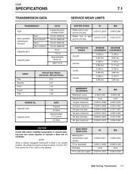
TURN SIGNALS 8.1 - harley-davidson-sweden.se
TURN SIGNALS 8.1 - harley-davidson-sweden.se
TURN SIGNALS 8.1 - harley-davidson-sweden.se
- No tags were found...

You also want an ePaper? Increase the reach of your titles
YUMPU automatically turns print PDFs into web optimized ePapers that Google loves.
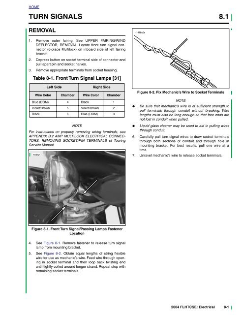
2HOME<strong>TURN</strong> <strong>SIGNALS</strong> <strong>8.1</strong>REMOVALf1418x2x1. Remove outer fairing. See UPPER FAIRING/WINDDEFLECTOR, REMOVAL. Locate front turn signal connector(6-place Multilock) on inboard side of left fairingbracket.2. Depress button on socket terminal side of connector andpull apart pin and socket halves.3. Remove appropriate terminals from socket housing.Table 8-1. Front Turn Signal Lamps [31]Left SideRight SideWire Color Chamber Wire Color ChamberBlue (DOM) 4 Black 1Violet/Brown 5 Violet/Brown 2Black 6 Blue (DOM) 3NOTEFor instructions on properly removing wiring terminals, <strong>se</strong>eAPPENDIX B.2 AMP MULTILOCK ELECTRICAL CONNEC-TORS, REMOVING SOCKET/PIN TERMINALS of TouringService Manual.10552●●Figure 8-2. Fix Mechanic’s Wire to Socket TerminalsNOTEBe sure that mechanic’s wire is of sufficient strength topull terminals through conduit without breaking. Wirelengths must also be long enough so that free ends arenot lost in conduit when pulled.Liquid glass cleaner may be u<strong>se</strong>d to aid in pulling wiresthrough conduit.6. Carefully pull turn signal wires to draw socket terminalsthrough both <strong>se</strong>ctions of conduit and through hole inmounting bracket. For best results, pull one wire at atime.7. Unravel mechanic’s wire to relea<strong>se</strong> socket terminals.Figure 8-1. Front Turn Signal/Passing Lamps FastenerLocation4. See Figure 8-1. Remove fastener to relea<strong>se</strong> turn signallamp from mounting bracket.5. See Figure 8-2. Obtain equal lengths of string flexiblewire for u<strong>se</strong> as mechanic’s wire. Feed wire through openingin socket terminal and then loop back twisting enduntil tightly coiled around longer strand. Repeat step withremaining socket terminals.2004 FLHTCSE: Electrical 8-1
HOMEINSTALLATION1. Lay old turn signal lamp next to new turn signal lamp andcut wires to length.2. Strip 3/16 inch (4.8 mm) of insulation off new lamp wiresand crimp on new socket terminals.NOTEFor instructions on crimping wire terminals, <strong>se</strong>e APPENDIXB.2 AMP MULTILOCK ELECTRICAL CONNECTORS,CRIMPING INSTRUCTIONS in Touring Service Manual.3. Reattach mechanic’s wire to socket terminals and carefullypull ends of mechanic’s wire to draw socket terminalsback through mounting bracket and conduit.4. Carefully remove mechanic’s wire to avoid damage toterminals.5. Install terminals into proper location of socket housing.6. Mate pin and socket halves of front turn signal connector.NOTEFor instructions on properly installing wire terminals, <strong>se</strong>eAPPENDIX B.2 AMP MULTILOCK ELECTRICAL CONNEC-TORS, INSTALLING SOCKET/PIN TERMINALS.7. Install fastener to <strong>se</strong>cure turn signal lamp to mountingbracket. Tighten to 96-120 in-lbs (10.8-13.6 Nm)8. Turn Ignition/Light Key Switch to IGNITION and test forproper operation.8-2 2004 FLHTCSE: Electrical
HOMEPASSING LAMPS AND BRACKET 8.2REMOVAL1. Remove outer fairing. See UPPER FAIRING/WIND-SHIELD REMOVAL in Touring Models Service Manual.2. Locate front passing lamp connector.3. Depress button on socket terminal side of connector andpull apart pin and socket halves.4. See Figure 8-1. Remove fasteners from bottom of passinglamp.5. Remove complete passing lamp from bracket whileslowly pulling wires through bracket.INSTALLATIONNOTEFor instructions on properly installing wire terminals, <strong>se</strong>eAPPENDIX B.2 AMP MULTILOCK ELECTRICAL CONNEC-TORS, INSTALLING SOCKET/PIN TERMINALS in TouringModels Service Manual.1. Install new2. See Figure 8-2. Attach mechanic’s wire to socket terminalsand carefully pull ends of mechanic’s wire to drawsocket terminals back through mounting bracket andconduit.3. Carefully remove mechanic’s wire to avoid damage toterminals.4. Seat passing lamp onto passing lamp bracket, installpassing lamp fasteners and tighten to 15-18 ft-lbs(20.3-24.4 Nm).5. Install terminals into proper location of socket housing6. Mate pin and socket halves of passing lamp connector.2004 FLHTCSE: Electrical 8-3
HOMEz0064a19678921345101119181213171615141. Fastener2. Washer3. Fastener4. Washer5. Socket terminal6. Housing, passing lamp7. Ring, passing lamp8. Passing lamp9. Bezel ring, passing lamp10. Fastener11. Nut12. Washer13. Nut14. Lens, turn signal15. Bulb, amber16. Socket, turn signal17. Housing, turn signal18. Stand off19. BracketFigure 8-3. Front Turn Signal and Passing Lamp Components8-4 2004 FLHTCSE: Electrical
HOMEFRONT PASSING LAMP BRACKETS 8.3REMOVAL1. See Figure 8-3. Remove passing and front turn signallamps per procedures in the manual.2. Remove fasteners from bracket and remove bracket frommotorcycle.INSTALLATION1. Align bracket with mounting holes.2. Install washers and fasteners.3. Tighten fasteners to 15-20 ft-lbs (20.3-27.1 Nm).2004 FLHTCSE: Electrical 8-5
HOMEGARAGE DOOR OPENER 8.4TRANSMITTERRemoval1. Remove outer fairing. See Touring Models Service Manual.2. Locate transmitter on inner left side of fairing.3. Disconnect wiring harness connector.4. Remove transmitter from adhesive tape mount.InstallationNOTEBe certain to apply pressure to adhesive tape when installingtransmitter.1. Clean surface and apply new transmitter.2. Connect wires to harness.3. Verify correct function by verifying that the LED light ontransmitter blinks when the high-low beam switch is activated.4. Install outer fairing according to procedure in TouringModels Service Manual.RECEIVERInstallation1. Unplug power cord from garage door drive unit to preventdoor activation during installation.2. Find an unswitched 110V power outlet in garage that islocated either highest in the garage, or clo<strong>se</strong>st to front ofgarage, or both. Locate the Harley-Davidson remotecontrolgarage-door opener receiver here.NOTEWith some brands of garage door opener systems, it may benecessary to plug in the Harley-Davidson receiver at a locationsome distance away from the door opener. If the Harley-Davidson receiver is plugged in too clo<strong>se</strong> to the originalopener receiver, effective transmission range may be significantlyreduced on both systems.3. Find the two garage-door-activation switch terminals onone of the<strong>se</strong> locations:a. The existing wall-mounted, hard wired garage dooropener buttonb. The garage-door drive unit to which the garagedoor-openerbutton is connected4. Fasten stripped end of Harley-Davidson garage-dooropener receiver wires to door-opener terminals that activatedoor opener drive unit. Refer to door-opener manufacturer’sdocumentation for terminal locations andconnections.i04101Figure 8-4. Garage Door Opener Receiver, Back ViewNOTEDo not remove original wires from original connections on thedoor-opener button or on drive-unit terminals.5. As<strong>se</strong>mble and install garage-door opener button in itsoriginal location.6. Route Harley-Davidson garage-door opener wires connectedin step 4 to power outlet <strong>se</strong>lected in step 2.7. See Figure 8-4. Plug connector on Harley-Davidsongarage-door opener receiver wires into back of Harley-Davidson garage-door opener receiver.8. Plug garage-door opener receiver into <strong>se</strong>lected poweroutlet.9. Plug power cord from garage-door drive unit into poweroutlet.10. Press wall-mounted garage-door-opener button to testbutton operation.REMOTE CONTROL GARAGE DOOROPENERFCC NoticesNOTEChanges or modifications to this unit not expressly approvedby the manufacturer could void the u<strong>se</strong>r’s authority to operatethe equipment.This equipment has been tested and found to comply with thelimits for Class B digital devices pursuant to Part 15, SubpartB of the FCC Rules. The<strong>se</strong> limits are designed to provide reasonableprotection against harmful interference in a residentialenvironment. This equipment generates, u<strong>se</strong>s, and canradiate radio frequency energy, and if not installed and u<strong>se</strong>din accordance with the instruction manual, may cau<strong>se</strong> harmfulinterference to radio communications. However, there is no8-6 2004 FLHTCSE: Electrical
HOMEguarantee that interference will not occur in a particular installation.If this equipment does cau<strong>se</strong> harmful interference toradio or television reception, which can be determined byturning the equipment off and on, the u<strong>se</strong>r is encouraged totry to correct the interference by one or more of the followingmeasures.• Reorient or relocate the receiving antenna.• Increa<strong>se</strong> the distance between the equipment and thereceiver.• Connect the equipment to an outlet on a circuit differentfrom that to which the receiver is connected.Program the Receiver and TransmitterThe receiver must be programmed to receive the transmitterfrequency. This process may require two people, dependingon how far apart the receiver and transmitter are during theprogramming process.1. Check that a red light is visible on the front of the Harley-Davidson garage door opener receiver, indicating powerto the receiver.i04102• Consult the dealer or an experienced radio/TV technicianfor help.NOTEWith some brands of garage door opener systems, it may benecessary to plug in the Harley-Davidson receiver at a locationsome distance from the door opener. If the Harley-Davidsonreceiver is plugged in too clo<strong>se</strong> to the original openerreceiver, effective transmission range may be significantlyreduced on both systems.11. Find the two garage door activation switch terminals onone of the<strong>se</strong> locations:a. The existing wall mounted, hand wired garage dooropener button.b. The garage door drive unit to which the garage dooropener button is connected.12. Fasten the stripped end of the Harley-Davidson garagedoor opener receiver wires to the door opener terminalsthat activate the door opener drive unit. Refer to the dooropener manufacturer’s documentation for terminal locationsand connections.NOTEDo not remove original wires from the original connections onthe door opener button or on the drive unit terminals.13. As<strong>se</strong>mble and install the garage door opener button in itsoriginal location.14. Route the Harley-Davidson garage door opener receiverwires connected in Step 4 to the power outlet <strong>se</strong>lected inStep 2.15. See Figure 8-5. Plug the connector on the Harley-Davidsongarage door opener receiver wires into the back ofthe Harley-Davidson garage door opener receiver.16. Plug the garage door opener receiver into the <strong>se</strong>lectedpower outlet.17. Plug the power cord from the garage door drive unit intothe power outlet.18. Press the wall mounted garage door opener button to <strong>se</strong>tthe button operation.Figure 8-5. Garage Door Opener Receiver, Front View2. See Figure 8-5. Press and hold the Set button the Harley-Davidsongarage door opener receiver. The LEDblinks continuously while the Set button is pres<strong>se</strong>d.3. Set the motorcycle ignition switch to IGN. Switch theheadlamp beam switch using one of the<strong>se</strong> <strong>se</strong>quences:a. Starting from Low beam, switch High, then Lowb. Starting from high beam, switch Low, then HighNOTEWhen the receiver receives a signal from the transmitter, theLED on the transmitter turns off.4. Relea<strong>se</strong> the Set button on the receiver.11WARNING 1WARNINGCheck for proper lighting and switch operation beforeriding motorcycle. Visibility is a major concern for motorcyclists.Failure to have proper lighting and signal lampoperation could result in death or <strong>se</strong>rious injury.NOTEClear all obstructions away from between the transmitter andreceiver before testing the operation of the garage dooropener.5. Test the garage door opener, high beam, and low beamheadlamp operation.NOTEWhen the transmitter is activated by toggling the headlampswitch, the red LED on the transmitter illuminates for one <strong>se</strong>condto indicate that the transmitter is functioning correctly.6. Set the motorcycle ignition switch to OFF.2004 FLHTCSE: Electrical 8-7
HOMEWIRING HARNESS OVERLAY 8.5f2282x0x1 23541. Ground stud (left) [GRND1]2. Fu<strong>se</strong> relay block (cavity 2H) [64]3. Speaker, front (left) [35]4. Speaker, front (right) [34]5. Main harness connection [27]Figure 8-6. Wiring Harness Overlay8-8 2004 FLHTCSE: Electrical