System Implications in Designing a 60 GHz WLAN RF Front-End
System Implications in Designing a 60 GHz WLAN RF Front-End
System Implications in Designing a 60 GHz WLAN RF Front-End
- No tags were found...

You also want an ePaper? Increase the reach of your titles
YUMPU automatically turns print PDFs into web optimized ePapers that Google loves.
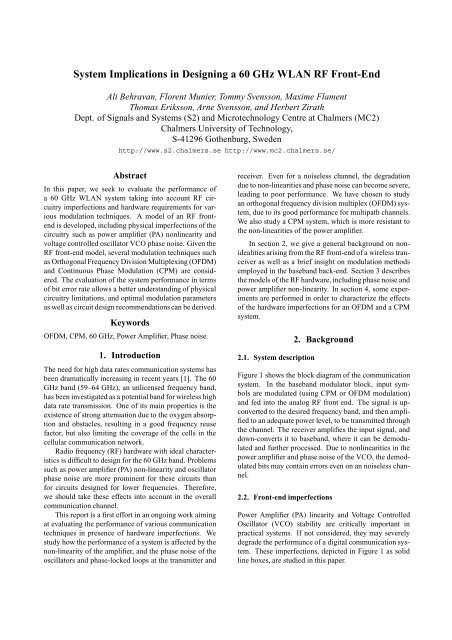
<strong>System</strong> <strong>Implications</strong> <strong>in</strong> Design<strong>in</strong>g a <strong>60</strong> <strong>GHz</strong> <strong>WLAN</strong> <strong>RF</strong> <strong>Front</strong>-<strong>End</strong>Ali Behravan, Florent Munier, Tommy Svensson, Maxime FlamentThomas Eriksson, Arne Svensson, and Herbert ZirathDept. of Signals and <strong>System</strong>s (S2) and Microtechnology Centre at Chalmers (MC2)Chalmers University of Technology,S-41296 Gothenburg, Swedenhttp://www.s2.chalmers.se http://www.mc2.chalmers.se/AbstractIn this paper, we seek to evaluate the performance ofa <strong>60</strong> <strong>GHz</strong> <strong>WLAN</strong> system tak<strong>in</strong>g <strong>in</strong>to account <strong>RF</strong> circuitryimperfections and hardware requirements for variousmodulation techniques. A model of an <strong>RF</strong> frontendis developed, <strong>in</strong>clud<strong>in</strong>g physical imperfections of thecircuitry such as power amplifier (PA) nonl<strong>in</strong>earity andvoltage controlled oscillator VCO phase noise. Given the<strong>RF</strong> front-end model, several modulation techniques suchas Orthogonal Frequency Division Multiplex<strong>in</strong>g (OFDM)and Cont<strong>in</strong>uous Phase Modulation (CPM) are considered.The evaluation of the system performance <strong>in</strong> termsof bit error rate allows a better understand<strong>in</strong>g of physicalcircuitry limitations, and optimal modulation parametersas well as circuit design recommendations can be derived.KeywordsOFDM, CPM, <strong>60</strong> <strong>GHz</strong>, Power Amplifier, Phase noise.1. IntroductionThe need for high data rates communication systems hasbeen dramatically <strong>in</strong>creas<strong>in</strong>g <strong>in</strong> recent years [1]. The <strong>60</strong><strong>GHz</strong> band (59–64 <strong>GHz</strong>), an unlicensed frequency band,has been <strong>in</strong>vestigated as a potential band for wireless highdata rate transmission. One of its ma<strong>in</strong> properties is theexistence of strong attenuation due to the oxygen absorptionand obstacles, result<strong>in</strong>g <strong>in</strong> a good frequency reusefactor, but also limit<strong>in</strong>g the coverage of the cells <strong>in</strong> thecellular communication network.Radio frequency (<strong>RF</strong>) hardware with ideal characteristicsis difficult to design for the <strong>60</strong> <strong>GHz</strong> band. Problemssuch as power amplifier (PA) non-l<strong>in</strong>earity and oscillatorphase noise are more prom<strong>in</strong>ent for these circuits thanfor circuits designed for lower frequencies. Therefore,we should take these effects <strong>in</strong>to account <strong>in</strong> the overallcommunication channel.This report is a first effort <strong>in</strong> an ongo<strong>in</strong>g work aim<strong>in</strong>gat evaluat<strong>in</strong>g the performance of various communicationtechniques <strong>in</strong> presence of hardware imperfections. Westudy how the performance of a system is affected by thenon-l<strong>in</strong>earity of the amplifier, and the phase noise of theoscillators and phase-locked loops at the transmitter andreceiver. Even for a noiseless channel, the degradationdue to non-l<strong>in</strong>earities and phase noise can become severe,lead<strong>in</strong>g to poor performance. We have chosen to studyan orthogonal frequency division multiplex (OFDM) system,due to its good performance for multipath channels.We also study a CPM system, which is more resistant tothe non-l<strong>in</strong>earities of the power amplifier.In section 2, we give a general background on nonidealitiesaris<strong>in</strong>g from the <strong>RF</strong> front-end of a wireless tranceiveras well as a brief <strong>in</strong>sight on modulation methodsemployed <strong>in</strong> the baseband back-end. Section 3 describesthe models of the <strong>RF</strong> hardware, <strong>in</strong>clud<strong>in</strong>g phase noise andpower amplifier non-l<strong>in</strong>earity. In section 4, some experimentsare performed <strong>in</strong> order to characterize the effectsof the hardware imperfections for an OFDM and a CPMsystem.2.1. <strong>System</strong> description2. BackgroundFigure 1 shows the block diagram of the communicationsystem. In the baseband modulator block, <strong>in</strong>put symbolsare modulated (us<strong>in</strong>g CPM or OFDM modulation)and fed <strong>in</strong>to the analog <strong>RF</strong> front end. The signal is upconvertedto the desired frequency band, and then amplifiedto an adequate power level, to be transmitted throughthe channel. The receiver amplifies the <strong>in</strong>put signal, anddown-converts it to baseband, where it can be demodulatedand further processed. Due to nonl<strong>in</strong>earities <strong>in</strong> thepower amplifier and phase noise of the VCO, the demodulatedbits may conta<strong>in</strong> errors even on an noiseless channel.2.2. <strong>Front</strong>-end imperfectionsPower Amplifier (PA) l<strong>in</strong>earity and Voltage ControlledOscillator (VCO) stability are critically important <strong>in</strong>practical systems. If not considered, they may severelydegrade the performance of a digital communication system.These imperfections, depicted <strong>in</strong> Figure 1 as solidl<strong>in</strong>e boxes, are studied <strong>in</strong> this paper.
Baseband ModulationIF AmpMixer<strong>RF</strong> PALeeson’s noise spectrum model described <strong>in</strong> [6]. Moreon this can be found <strong>in</strong> section 3.2.Baseband Demodulation4X2X"Black Box" <strong>60</strong><strong>GHz</strong> VCO modelIF AmpSplitterMixerLNA<strong>60</strong><strong>GHz</strong> ChannelFigure 1: <strong>60</strong> <strong>GHz</strong> transceiver front-end. Solid l<strong>in</strong>es boxes<strong>in</strong>clude non-ideal properties studied <strong>in</strong> this paper. Thebaseband modulation <strong>in</strong>vestigated are both QPSK/OFDMand CPM schemes.2.2.1. Amplifier nonl<strong>in</strong>earitiesMany transmission systems and particularly multicarriersystems show a notable sensitivity to the non-l<strong>in</strong>ear effectscaused by the use of non-l<strong>in</strong>ear amplifiers. Thenon-l<strong>in</strong>ear distortions cause signal compression creat<strong>in</strong>g<strong>in</strong>terference between subcarriers [2] called Inter-CarrierInterference (ICI). In order to ma<strong>in</strong>ta<strong>in</strong> acceptable performance<strong>in</strong> presence of nonl<strong>in</strong>earities, large <strong>in</strong>put back-offmay be required result<strong>in</strong>g <strong>in</strong> low power efficiency. Therefore,a study of the system is required to f<strong>in</strong>d a reasonabletrade-off between transmitted power and l<strong>in</strong>k performanceof the system.2.2.2. VCO phase noiseAnother important matter when it comes to design a wirelesstransceiver is the quality of the VCO. The amount ofphase noise present <strong>in</strong> the VCO is a measure of this quality,usually given as a ratio of power <strong>in</strong> one phase modulationsideband to the total power per unit bandwidth, ordBc/Hz at a certa<strong>in</strong> offset from the carrier frequency.1One can see phase noise as a random change <strong>in</strong> the phaseterm of the oscillator.The existence of this perturbation leads to a mismatchedup/down-conversion of the signal. In multicarrierschemes like OFDM, phase noise is a particularlysensitive factor that causes subcarriers to <strong>in</strong>terfere betweeneach other and hence <strong>in</strong>creases the error probabilityof the communication l<strong>in</strong>k. Another effect of phasenoise is <strong>in</strong>troduc<strong>in</strong>g some uncerta<strong>in</strong>ty <strong>in</strong> the modulatedsignal. Phase noise and more generally ½ « noise generationfor simulation has been extensively studied <strong>in</strong> [3]and [4]. Some results are reported regard<strong>in</strong>g effects onOFDM systems <strong>in</strong> [5]. There are several ways of model<strong>in</strong>gthe phase noise process such as an AR filter basedmodel [3], or by shap<strong>in</strong>g the frequency response of phasenoise accord<strong>in</strong>g to some practical measurements us<strong>in</strong>g1 dBc denotes the decibels relative to the carrier power.2.3. Modulation methodsAmong the exist<strong>in</strong>g modulation methods, we focused onOFDM and CPM. OFDM issues <strong>in</strong> broadband wirelesssystems have been widely discussed [1] and considerationsfor <strong>60</strong> <strong>GHz</strong> channel have been reported <strong>in</strong> [7].CPM is seen as an attractive modulation technique due toits constant envelope that makes it less sensitive to nonl<strong>in</strong>earities.2.3.1. OFDMOrthogonal Frequency Division Multiplex<strong>in</strong>g (OFDM) isa multicarrier transmission technique, which divides theavailable spectrum <strong>in</strong>to a number of subchannels, eachone be<strong>in</strong>g modulated by a low rate data stream. OFDMuses the spectrum efficiently by overlapp<strong>in</strong>g the subchannels<strong>in</strong> such a way that they are kept orthogonal [8].OFDM transmission schemes are particularly <strong>in</strong>terest<strong>in</strong>g<strong>in</strong> the presence of time dispersion of the channel due tomultiple paths arriv<strong>in</strong>g at different time. Another advantageis the possibility to adjust the data rate of each subcarrieraccord<strong>in</strong>g to their Signal-to-Noise ratio. On theother hand, OFDM presents several drawbacks of whichtwo of them are analyzed <strong>in</strong> this paper. First, the OFDMsignal is more sensitive to frequency mismatch and phasenoise compared to s<strong>in</strong>gle carrier schemes. Second, thehigh peak-to-average power ratio of an OFDM signal requiresl<strong>in</strong>ear amplifiers, which tend to be costly and toreduce the power efficiency. Both effects deteriorate theorthogonality between subcarriers and <strong>in</strong>troduce ICI.2.3.2. CPMIn Cont<strong>in</strong>uous Phase Modulation (CPM) the <strong>in</strong>formationsymbols are transmitted by chang<strong>in</strong>g the phase of a carriersignal. The transmitted phase function is cont<strong>in</strong>uousover time for all symbol sequences, which makes the envelopeof the transmitted signal to be constant. Therefore,non-l<strong>in</strong>ear amplifiers are not a problem. In addition, thecont<strong>in</strong>uous phase function <strong>in</strong> CPM creates small spectralside lobes as compared to e.g. the discont<strong>in</strong>uous phasefunction <strong>in</strong> constant amplitude PSK. Each CPM symbolis transmitted by a phase function called the phase responsefunction, hav<strong>in</strong>g an amplitude depend<strong>in</strong>g on theCPM symbol, and the transmitted phase is a superpositionof these phase functions. The total phase change foreach symbol depends on a parameter called the modulation<strong>in</strong>dex, . A common notation for CPM with a l<strong>in</strong>earphase response function of length one is Cont<strong>in</strong>uousPhase Frequency Shift Key<strong>in</strong>g (CPFSK). The cont<strong>in</strong>uousphase restriction and phase response functions longerthan one CPM symbol <strong>in</strong>troduces f<strong>in</strong>ite memory <strong>in</strong> themodulation. Hence, the Viterbi algorithm is an optimum
eceiver for CPM on the AWGN channel. A standard referenceof CPM is [9].3. Model<strong>in</strong>g the front-end imperfectionsIn this section, we describe the models we have employed<strong>in</strong> order to simulate the front-end. We focus our attentionon the power amplifier <strong>in</strong> the transmitter, and on theoscillators <strong>in</strong> the transmitter and the receiver. We havederived equivalent baseband models of the amplifier nonl<strong>in</strong>earitiesand the phase noise.3.1. Baseband equivalent model of the non-l<strong>in</strong>ear amplifierThe non-l<strong>in</strong>ear characteristic of the amplifier can befound us<strong>in</strong>g s<strong>in</strong>gle tone measurements. The nonl<strong>in</strong>earitiesare usually represented by a power series. The <strong>in</strong>putoutput relationship of a nonl<strong>in</strong>ear amplifier can thus bewritten asݴص ´Ü´Øµµ ÆÒ½ Ò Ü Ò´Øµ (1)where ܴص is the modulated signal at the <strong>in</strong>put of the amplifier,ܴص ´Øµ Ó×´¾ ¼ Ø · ´Øµµ (2)Both ´Øµ and ´Øµ are narrow band baseband signal.Writ<strong>in</strong>g ܴص <strong>in</strong> terms of its equivalent low-pass, andsubstitut<strong>in</strong>g <strong>in</strong> (1), it emerges that only odd terms <strong>in</strong> theseries contribute <strong>in</strong> the output around the desired frequencyband, and the equivalent <strong>in</strong>put-output relation <strong>in</strong>the baseband can be written asݴص ¾Æ ½Ñ¼ ¾Ñ·½¾ ¾Ñ ¾Ñ ·½Ñ ·½Ü´Øµ ¾Ñ·½ ´Øµ (3)where ܴص and ݴص are equivalent baseband <strong>in</strong>put andoutput of the nonl<strong>in</strong>ear amplifier.A similar procedure can be followed to f<strong>in</strong>d the effectof the <strong>in</strong>termodulation terms <strong>in</strong> the baseband [10] but thisis not considered <strong>in</strong> this study. The <strong>in</strong>put-output characteristicof the nonl<strong>in</strong>ear amplifier is shown <strong>in</strong> figure 2.The model was derived by fitt<strong>in</strong>g a power series to theamplitude and phase curves of a <strong>60</strong> <strong>GHz</strong> power amplifier.3.2. Baseband Representation of Phase NoisePhase noise orig<strong>in</strong>ates from several sources; one partstems from <strong>in</strong>stabilities <strong>in</strong> the transmitter oscillator, anotherpart from the receiver oscillator, but also Dopplereffects and channel noise pass<strong>in</strong>g through the phaselockedloop contributes to the total phase noise. In thisdocument, we generate the phase noise process ´Øµ asa Gaussian distributed random process with a variancePSD [dBc/Hz]0−20−40−<strong>60</strong>−80−100Pout (dBm)22201816141210864−4 −2 0 2 4 6 8 10 12 14P<strong>in</strong> (dBm)Figure 2: AM-AM effect <strong>in</strong> nonl<strong>in</strong>ear amplifier−12010 −1 10 0 10 1 10 2 10 3 10 4 10 5Frequency [Hz]Figure 3: Phase noise power spectral density.Ò ¾ . Its spectrum is def<strong>in</strong>ed by an AR filter whose transferfunction is given asÀ´Þµ (4)½ «Þ ½where and « are parameters used to control the cutofffrequency and the power of the phase noise. The spectrumof phase noise generated by this model is shown <strong>in</strong>figure (3).We also def<strong>in</strong>e a phase SNR asËÆÊ ½¼ÐÓ ½¼´ ¾ ¾ Òµ (5)where ¾ Ò is the phase noise power. Here it is important tonotice that a VCO with phase noise will have a result<strong>in</strong>gbandwidth which is not only vary<strong>in</strong>g with the phase noisepower but also with the phase noise process bandwidththat is dictated by the AR filter.Ideally, a complex baseband signal ܴص ´Øµ ´Øµis upconverted by a phase noise-free VCO with center
frequency ¼ and the output of the mixer is given byܴص ʴص ¾¼Ø·´Øµ (6)However, due to physical imperfections present <strong>in</strong> theVCO, the phase of the carrier is not fixed but rather affectedby a random phase noise process ´Øµ so that ܴصbecomesQ3210−1ܴص ʴص ¾¼Ø·´Øµ·´Øµ (7)The equivalent complex baseband modulation affected byphase noise isܴص ´Øµ ´Øµ·´Øµ (8)This process can be used to simulate the total phase noiseexperienced by the modulation. We may look at ´Øµas the comb<strong>in</strong>ation of phase disturbances occur<strong>in</strong>g <strong>in</strong>the transmitter and receiver oscillators as well as disturbancesaris<strong>in</strong>g from the channel (e.g Doppler shift).4. Experiments4.1. Simulation setup4.1.1. OFDMThe system <strong>in</strong> figure 1 is used as the setup for this simulation.An OFDM signal with 256 subcarriers, each modulatedby 16QAM or DQPSK, is generated <strong>in</strong> the basebandmodulator. Dur<strong>in</strong>g upconversion phase noise is <strong>in</strong>troducedby the oscillator, and the power amplifier willfurther distort the signal.4.1.2. CPMA CPM system consist<strong>in</strong>g of a transmitter and a Viterbidetector perform<strong>in</strong>g coherent detection, comb<strong>in</strong>ed witha simple phase estimator, has been simulated with thephase noise process. The CPM system is: b<strong>in</strong>ary CPFSKwith ½¾ (MSK) or 4-ary CPFSK with ½ andGray mapp<strong>in</strong>g, which gives 2 bits per CPM symbol.4.2. Results4.2.1. OFDMThe effect of amplifier non-l<strong>in</strong>earity on the OFDM signalcan be seen by look<strong>in</strong>g at the received signal constellationafter the FFT block. As shown <strong>in</strong> figure 4, due to therandomness of the nonconstant amplitude signal <strong>in</strong> eachsubcarrier <strong>in</strong>terval, a distribution of signal po<strong>in</strong>ts is received,<strong>in</strong>stead of a s<strong>in</strong>gle po<strong>in</strong>t. Also because of the amplifierga<strong>in</strong> compression, the center of these clouds getscloser to the orig<strong>in</strong>. Another effect is the rotation of thesignal space due to AM-PM effect. The variance of thedistribution is a function of the number of subcarriers and−2−3−3 −2 −1 0 1 2 3IFigure 4: Received signal constellation for N=256 andIBO=3.27dB0.080.0<strong>60</strong>.040.020−3 −2 −1 0 1 2 3AmplitudeFigure 5: PDF of the amplitude of OFDM signal with 256subcarriersthe center depends on the power of the transmitted signal.When the number of subcarriers is <strong>in</strong>creased, a Gaussiandistribution will be a valid approximation for the distributionof the received po<strong>in</strong>ts <strong>in</strong> the signal space (figure5). Therefore, the effect of the nonl<strong>in</strong>earity on the performanceof the system can be completely described by themean and the variance of the signal po<strong>in</strong>ts.Us<strong>in</strong>g a Gaussian approximation, the bit error rate ofan OFDM system with 256 subcarriers <strong>in</strong> the presence ofa non-l<strong>in</strong>earity has been computed. Note that because ofthe rotation of the signal space and the power compression,the received signal constellation is not symmetricaland the distance between adjacent po<strong>in</strong>ts <strong>in</strong> the signalconstellation are not the same. Therefore we can not usethe standard methods of calculat<strong>in</strong>g bit error rate for 16QAM. The conditional symbol error probability must befound first and then the total symbol error rate can bederived by averag<strong>in</strong>g the conditional probabilities. Figure6 shows simulation results for the bit error rate versusamplifier <strong>in</strong>put back-off <strong>in</strong> a noise-free system. TheBER versus SNR for a system <strong>in</strong>clud<strong>in</strong>g AWGN channelisshown<strong>in</strong>figure8.Figure 7 present BER results of an OFDM system us<strong>in</strong>gDQPSK, and of a standard DQPSK system, for differentphase SNR as def<strong>in</strong>ed <strong>in</strong> equation 5. In this simulation,we <strong>in</strong>ject a phase noise <strong>in</strong> the transmitted basebandsignal. We assume that phase noise is <strong>in</strong>troduced by the
transmitter and receiver VCOs without contribution fromthe channel.the OFDM system is highly sensitive to amplifier nonl<strong>in</strong>earitiesand oscillator phase noise. The CPM system isimmune towards amplifier nonl<strong>in</strong>earities, and less sensitivethan OFDM towards phase noise.10 −2 IBO (dB)BER10 −410 −610 −8IBO=3.27IBO=3.9IBO=4.6IBO=5.36IBO=6.19Without NL10 −2 Eb/No (dB)10 −100 2 4 610 −4Figure 6: Bit error rate versus amplifier <strong>in</strong>put backoff fora noise-free systemBER10 −610 0 Phase SNR (dB)10 −110 −810 −2Bit Error Probability10 −310 −410 −510 −610 −105 10 15 20 25 30QPSKOFDM−QPSK10 −7−10 −5 0 5 10 15 20 25 30Figure 8: Bit error rate versus SNR for different IBOsFigure 7: BER vs phase SNR for QPSK andQPSK/OFDM10 0 Phase SNR [dB]4.2.2. CPMIn the CPM system simulations, the phase noise processhas the same bandwidth as <strong>in</strong> the OFDM system simulations.Furthermore, the bandwidths of the CPM systemand the OFDM system are the same. This means thatwhen QPSK or DQPSK is used <strong>in</strong> the OFDM system and4-ary CPM is used <strong>in</strong> the CPM system, the bit rates arethe same.In figure 9 the bit error rate for CPM caused by thephase noise is shown. It is clearly seen that the 4-aryCPFSK is more sensitive to the phase noise, which is nosurprise s<strong>in</strong>ce the phase trajectories are much more densethan <strong>in</strong> MSK. However, the bit rate is twice as high withthe 4-ary CPFSK as compared to MSK.Bit Error Probability10 −210 −410 −6MSK4−ary CPFSK h=1/410 −8−25 −20 −15 −10 −5 0 5Figure 9: BER vs. phase SNR for MSK and 4-ary CPFSK ½.5. ConclusionsWe have performed system simulations of OFDM, CPM,and s<strong>in</strong>gle-carrier QPSK, <strong>in</strong>clud<strong>in</strong>g <strong>RF</strong> circuitry imperfections.The results show that with the assumed models,
6. References[1] Luis M. Correia and Ramjee Prasad, “An overviewof wireless broadband communication,” IEEE CommunicationsMagaz<strong>in</strong>e, pp. 28–33, Jan. 1997.[2] A. Vaccardi D. Dardari, V. Tralli, “A theoreticalcharacterization of nonl<strong>in</strong>ear distortion effects <strong>in</strong>ofdm systems,” <strong>in</strong> IEICE Transactions Communications.IEEE, Oct. 2000, vol. 48, pp. 1755–1764.[3] N.J Kasd<strong>in</strong>, “Discrete simulation of colored noiseand stochastic processes and 1/ « power law noisegeneration,” <strong>in</strong> Proceed<strong>in</strong>gs of the IEEE. IEEE,May 1995, vol. 83, pp. 802–827.[4] P.Balaban M.C Jeruchim and K.S Shanmugan, Simulationof Communication <strong>System</strong>s, Plenum Press,1992.[5] M. Van Bladel T. Pollet and M. Moeneclaey, “Bersensitivity of ofdm systems to carrier frequency offsetand wiener phase noise,” <strong>in</strong> IEICE TransactionsCommunications. IEEE, feb,mar,apr 1995, vol. 43,pp. 192–193.[6] D.B Leeson, “A simple model of feedback oscillatornoise spectrum,” <strong>in</strong> Proceed<strong>in</strong>gs of the IEEE. IEEE,1966, vol. 54, pp. 329–330.[7] Maxime Flament, On <strong>60</strong> <strong>GHz</strong> Wireless Communication<strong>System</strong>s, Licenciate thesis, Chalmers Universityof Technology, Gothenburg, Sweden, Dec.2000.[8] R. van Nee and R. Prasad, OFDM for Wireless MultimediaCommunications, Artech House, 2001.[9] J.B. Andersson, T. Aul<strong>in</strong>, and C.-E. Sundberg, DigitalPhase Modulation, Plenum Press, 1986.[10] K.G. Gard H. Gutierrez and M.B Steer, “Characterizationof spectral regrowth <strong>in</strong> microwave amplifiersbased on the non-l<strong>in</strong>ear transformation of a complexgaussian process,” <strong>in</strong> IEEE Transactions on MicrowaveTheory and Techniques. IEEE, July 1999,vol. 47, pp. 1059–1069.