Safety Switches with Separate Actuator, Plastic Housing
Safety Switches with Separate Actuator, Plastic Housing
Safety Switches with Separate Actuator, Plastic Housing

You also want an ePaper? Increase the reach of your titles
YUMPU automatically turns print PDFs into web optimized ePapers that Google loves.
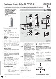
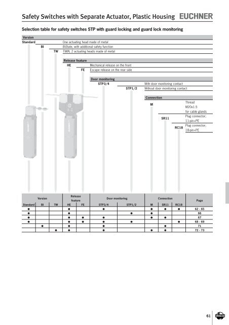
v<strong>Safety</strong> <strong>Switches</strong> <strong>with</strong> <strong>Separate</strong> <strong>Actuator</strong>, <strong>Plastic</strong> <strong>Housing</strong><strong>Safety</strong> switch STP <strong>with</strong> guard locking and guard lock monitoring1) Actuating head made of metal Mechanical release on the front With door monitoring contactCable entry M20 x 1.5Dimension drawing30InsertiondepthhInsertion depthvApproach direction435,341,30,5Horizontal and verticalCan be adjusted in 90° stepsMechanical releaseIs used for releasing the guard locking <strong>with</strong> the aid ofa tool. The mechanical release is sealed <strong>with</strong>sealing lacquer to prevent tampering.Solenoid operating voltage AC/DC 24 V +10%, -15% AC 110 V +10%, -15% AC 230 V +10%, -15%190LED indicator(optional)22M20x1,5 (3x)144For M5 > 35 mmISO 1207 (DIN 84)ISO 4762 (DIN 912)Mechanical releaseLocking screw43035,545,519h194LED function display (optional)A function display (2 LEDs, red and green) isavailable for the following voltage ranges: AC/DC 24 V +10%, -15%161630194Dimensions <strong>with</strong> insertion funnelGuard locking typesSTP3 Closed-circuit current principle, guard lockingby spring force. Release by applying voltageto the interlocking solenoid.STP4 Open-circuit current principle, guard lockingby applying voltage to the interlockingsolenoid. Release by spring force.Switching elements 537 Slow-action switching element1 NC + 1 NC (door monitoring contact)2131 Slow-action switching element2 NC + 1 NO + 1 NC (door monit. contact)4121 Slow-action switching element2 NC + 1 NC / 1 NO (door monit. contact)4131 Slow-action switching element2 NC + 1 NO + 1 NO (door monit. contact)4141 Slow-action switching element2 NC + 2NC (door monit. contacts)Please orderactuator separately(see pages 94-96)Wiring diagrams <strong>Actuator</strong> inserted and locked537LED22211211E1E2KL1KL2KL3KL453721 2211 12LEDs optionalRDGNFor switching functions see technical data on page 1352131LED1211424134332221E1E2KL1KL2KL3KL42131411 1241 4233 3421 22LEDs optionalRDGN932311441211342412221E1E2412131 3213 1441 4221 220,54131(<strong>with</strong> doormonitoring contact)41311413424134332221E1E213 1441 4233 3421 22For cable glands see page 104LED32311241411142412221E1E2414131 3211 1241 4221 22KL1RDKL2KL3GNKL4LEDs optionalSolenoid monitoringDoor monitoringOrdering tableSeries Connection Guard locking Switching element VersionSolenoid operating voltageAC/DC 24 V AC 110 V AC 230 V024L537 LED display AC/DC 24 V 0972101 NC + 1 NC D STP3D-537A024L024M On requestOn requestWith insertion funnel091493 099326 1059722131 STP3A-2131A024M STP3A-2131A110M STP3A-2131A230M2 NC + 1 NO + 1 NC 024L 091748LED display AC/DC 24 V STP3A-2131A024L024M On requestOn requestM4121 096890094792Cable 3 2 NC + 1 NC / 1 NO STP3A-4121A024M On request STP3A-4121A230MSTP entry Mechanical 4131 0917763 x2 NC + 1 NO + 1 NO STP3A-4131A024M On requestOn requestM20x1.5099272STP3A-4141A024M On requestOn requestD 0978914141 With insertion funnel STP3D-4141A024M On requestOn request2 NC + 2 NC 024LLED display AC/DC 24 V 099412DSTP3D-4141A024L024M On requestOn requestWith insertion funnel1) With cable entry M, DC 24 V / AC 110 V62Subject to technical modifications; no responsibility is accepted for the accuracy of this information.
<strong>Safety</strong> <strong>Switches</strong> <strong>with</strong> <strong>Separate</strong> <strong>Actuator</strong>, <strong>Plastic</strong> <strong>Housing</strong>Plug connector RC1818-pin + PEDimension drawing30InsertiondepthhInsertion depthvPlease orderactuator separately(see pages 82-84)435,341,30,5For M5 > 35 mmISO 1207 (DIN 84)ISO 4762 (DIN 912)Mechanical releasePlease orderactuator separately(see pages 94-96)For plug connectors see page 101/102Wiring diagrams <strong>Actuator</strong> inserted and lockedSolenoid monitoringFor switching functions see technical data on page 135Door monitoringFor safety precautions see page 160For technical data see page 117190LaLED indicator(optional)M20x1,5 (3x)14430Locking screw22221616490,5213151111 128RC1871441 42131033 34921 221719LED1516GNRDLEDs optionalOrdering tableSeries Connection Guard locking Switching element VersionSTPRC18PlugConnectorSolenoid operating voltageAC/DC 24 V3 2131 024L 099644Mechanical 2 NC + 1 NO + 1 NC LED display AC/DC 24 V STP3A-2131A024L024RC18Subject to technical modifications; no responsibility is accepted for the accuracy of this information. 65
<strong>Safety</strong> <strong>Switches</strong> <strong>with</strong> <strong>Separate</strong> <strong>Actuator</strong>, <strong>Plastic</strong> <strong>Housing</strong><strong>Safety</strong> switch STP <strong>with</strong> guard locking and guard lock monitoring Actuating head made of metal Mechanical release on the front Without door monitoring contactCable entry M20 x 1.5Dimension drawing30InsertiondepthhInsertion depthApproach directionHorizontal and verticalCan be adjusted in 90° steps4v35,341,30,5For M5 > 35 mmISO 1207 (DIN 84)ISO 4762 (DIN 912)Mechanical releaseMechanical releaseIs used for releasing the guard locking <strong>with</strong> the aid ofa tool. The mechanical release is sealed <strong>with</strong>sealing lacquer to prevent tampering.190M20x1,5 (3x)144Locking screwSolenoid operating voltage AC/DC 24 V +10%, -15% AC 110 V +10%, -15% AC 230 V +10%, -15%LED function display (optional)A function display (2 LEDs, red and green) isavailable for the following voltage ranges: AC/DC 24 V +10%, -15%Guard locking typesSTP1 Closed-circuit current principle, guard lockingby spring force. Release by applying voltageto the interlocking solenoid.STP2 Open-circuit current principle, guard lockingby applying voltage to the interlockingsolenoid. Release by spring force.Switching elements 528 Slow-action switching element1 NC + 1 NO538 Slow-action switching element2 NC4131 Slow-action switching element2 NC + 2 NOPlease orderactuator separately(see pages 94-96)22Wiring diagrams <strong>Actuator</strong> inserted and locked52814132221E1E25281613 1421 22538LED12112221E1E2KL1KL2KL3KL45381611 1221 22LEDs optionalRDGN43094131(<strong>with</strong>out doormonitoring contact)4131LED4241343322211413E1E2KL1KL2KL3KL441 4233 3421 2213 14LED display (optional)RDGN0,5For cable glands see page 104LEDs optionalSolenoid monitoringFor switching functions see technical data on page 134Door monitoringOrdering tableSeries Connection Guard locking Switching element VersionSolenoid operating voltageAC/DC 24 V AC 110 V AC 230 V528 0922661 NC + 1 NO STP1A-528A024MOn requestOn request092258STP1A-538A024MOn requestOn request538 024L1 2 NC LED display AC/DC 24 V 092489Mechanical <strong>with</strong> pre-assembled STP1D-538A024L024MOn requestOn requestinsertion funnelSTP091491MOn requestOn request4131 STP1A-4131A024MCable entry2 NC + 2 NO 024L 0917463 x M20 x 1.5On requestOn requestLED display AC/DC 24 V STP1A-4131A024L024M528 0998551 NC + 1 NO STP2A-528A024MOn requestOn request092260538 STP2A-538A024MOn requestOn request2 NC 024L 0924902 LED display AC/DC 24 V STP2A-538A024L024MOn requestOn requestElectrical 0914924131 STP2A-4131A024MOn requestOn request2 NC + 2 NO 024L 091747LED display AC/DC 24 V STP2A-4131A024L024MOn requestOn request66Subject to technical modifications; no responsibility is accepted for the accuracy of this information.
<strong>Safety</strong> <strong>Switches</strong> <strong>with</strong> <strong>Separate</strong> <strong>Actuator</strong>, <strong>Plastic</strong> <strong>Housing</strong><strong>Safety</strong> switch STP <strong>with</strong> guard locking and guard lock monitoring Escape release on the rear side With door monitoring contactCable entry M20 x 1.5Plug connector SR1111-pin + PEDimension drawing30InsertiondepthhInsertion depth435,5v41,50,5Approach directionHorizontal and verticalCan be adjusted in 90° steps1903661,553Ø 1467,5144144For M5 > 35 mmISO 1207 (DIN 84)ISO 4762 (DIN 912)Mechanical releaseEscape releaseIs used for the manual release of the guard lockingfrom <strong>with</strong>in the danger area <strong>with</strong>out tools. Withidentification of On/Off position.2274,730Locking screwSolenoid operating voltage AC/DC 24 V +10%, -15%16M20x1,5 (3x)28Guard locking typesSTP3 Closed-circuit current principle, guardlocking by spring force. Release byapplying voltage to the interlockingsolenoid.STP4 Open-circuit current principle, guard lockingby applying voltage to the interlockingsolenoid. Release by spring force.Please orderactuator separately(see pages 94-96) For cable glands see page 104Wiring diagrams <strong>Actuator</strong> inserted and locked16Please orderactuator separately(see pages 94-96)40,59For plug connectors see page 100Switching elements2131 Slow-action switching element2 NC + 1 NO + 1 NC(door monitoring contact)4121 Slow-action switching element2 NC + 1 NC / 1 NO(door monitoring contact)21311211424134332221E1E2213111 1241 4233 3421 2232311441211342412221E1E2412131 3213 1441 4221 22SR1121876543910213111 1241 4233 3421 22Solenoid monitoringSolenoid monitoringDoor monitoringDoor monitoringFor switching functions see technical data on page 135 For switching functions see technical data on page 135Ordering tableSeries Connection Guard locking Switching element VersionSolenoid operating voltageAC/DC 24 V2131 C1993 102267M3 2 Ö + 1 S + 1 Ö Long actuator shaft STP3A-2131A024MC1993CableMechanical 4121 C1993 096885entry2 Ö + 1 Ö / 1 S Long actuator shaft STP3A-4121A024MC1993STP3 x4 4121 C1993 100322M20 x 1.5Electrical 2 Ö + 1 Ö / 1 S Long actuator shaft STP4A-4121A024MC1993SR11Plug3 2131 C1993 103223Mechanical 2 Ö + 1 S + 1 ÖLong actuator shaftconnectorSTP3A-2131A024SR11C1993For safety precautions see page 160For technical data see page 117Subject to technical modifications; no responsibility is accepted for the accuracy of this information. 67
<strong>Safety</strong> <strong>Switches</strong> <strong>with</strong> <strong>Separate</strong> <strong>Actuator</strong>, <strong>Plastic</strong> <strong>Housing</strong><strong>Safety</strong> switch STP <strong>with</strong> guard locking and guard lock monitoring Actuating head made of metal Mechanical release on the front Pushbutton and cover for indicator With door monitoring contactPlug connector RC1818-pin + PEDimension drawing30InsertiondepthhInsertion depth435,541,530For safety precautions see page 160For technical data see page 117v0,5Approach directionHorizontal and verticalCan be adjusted in 90° stepsMechanical releaseIs used for releasing the guard locking <strong>with</strong> the aid ofa tool. The mechanical release is sealed <strong>with</strong>sealing lacquer to prevent tampering.Solenoid operating voltage AC/DC 24 V +10%, -15%Cover for indicatorA cover for indicators (1 LED, green) is availablefor following voltage ranges: DC 24 V +10%, -15%Guard locking typesSTP3 Closed-circuit current principle, guardlocking by spring force. Release byapplying voltage to the interlockingsolenoid.Switching elements4141 Slow-action switching element2 NC + 2NC (door monit. contacts)Please orderactuator separately(see pages 94-96)19022465616M20x1,5 (3x)Wiring Anschlusspläne diagrams Betätiger <strong>Actuator</strong> gesteckt inserted und and zugehalten lockedSolenoid monitoring144Pos. 1Pos. 2For M5 > 35 mmISO 1207 (DIN 84)ISO 4762 (DIN 912)Mechanical releaseLocking screwGreen coverfor indicatorBlack buttonDoor monitoringSchaltfunktionen For switching functions siehe technische see technical Daten data Seite on page 135 135Ordering tableSeries Connection Guard locking Switching element VersionSolenoid operating voltageAC/DC 24 VSTPPos. 1:RC183 4141 Green cover for indicator 104995PlugMechanical 2 NC + 2 NC Pos. 2: STP3A-4141A024RC18EXT1connectorBlack buttonRC184141 EXT1652187439191113141531 3211 1241 4221 22GNFor plug connectors see page 101/102Subject to technical modifications; no responsibility is accepted for the accuracy of this information. 69
<strong>Safety</strong> <strong>Switches</strong> <strong>with</strong> <strong>Separate</strong> <strong>Actuator</strong>, <strong>Plastic</strong> <strong>Housing</strong><strong>Safety</strong> switch STP <strong>with</strong> guard locking and guard lock monitoring Actuating head made of metal Escape release on the rear side 2 illuminated pushbuttons With door monitoring contactPlug connector RC1818-pin + PEDimension drawing30InsertiondepthhInsertion depthApproach directionHorizontal and verticalCan be adjusted in 90° steps190,3435,841,81461,55374,7Escapereleasenorm. position67,5144 vPos. 10,5For M5 > 35 mmISO 1207 (DIN 84)ISO 4762 (DIN 912)Mechanical releaseLocking screwButtonilluminated yellowEscape releaseIs used for the manual release of the guardlocking from <strong>with</strong>in the danger area <strong>with</strong>out tools.With identification of On/Off position.Solenoid operating voltage AC/DC 24 V +10%, -15%LED buttonA cover for indicators (1 LED, green) is availablefor following voltage ranges: DC 24 V +10%, -15%Guard locking typesSTP3 Closed-circuit current principle, guardlocking by spring force. Release byapplying voltage to the interlockingsolenoid.Switching elements4141 Slow-action switching element2 NC + 2NC (door monit. contacts)22Please orderactuator separately(see pages 94-96)22164656M20x1,5 (3x)UnlockedAnschlusspläne Wiring diagramsBetätiger gesteckt und zugehalten4141 EXT4<strong>Actuator</strong> inserted and locked6RC1852187439191117131631 3211 1241 4221 22YEWHPos. 230Buttonilluminated whiteFor plug connectors see page 101/102MagnetüberwachungSolenoid monitoringDoor Türüberwachung monitoring1514Schaltfunktionen For switching functions siehe technische see technical Daten data Seite on page 135 113Ordering tableSeries Connection Guard locking Switching element VersionSolenoid operating voltageAC/DC 24 VC1993STPLong actuator shaftRC183 4141 Pos. 1: 109399PlugMechanical 2 NC + 2 NC Yellow button STP3A-4141A024RC18C1993EXT4connectorPos. 2:White button70Subject to technical modifications; no responsibility is accepted for the accuracy of this information.
<strong>Safety</strong> <strong>Switches</strong> <strong>with</strong> <strong>Separate</strong> <strong>Actuator</strong>, <strong>Plastic</strong> <strong>Housing</strong><strong>Safety</strong> switch STP-BI <strong>with</strong> guard locking and guard lock monitoring Actuating head made of metal Mechanical release on the front Additional function BI-State With door monitoring contactPlug connector SR1111-pin + PEDimension drawingInsertiondepthhInsertion depthv0,5For M5 > 35 mmISO 1207 (DIN 84)ISO 4762 (DIN 912)Mechanical releaseApproach directionHorizontal and verticalCan be adjusted in 90° steps144Locking screw30Mechanical releaseIs used for releasing the guard locking <strong>with</strong> the aid ofa tool. The mechanical release is sealed <strong>with</strong>sealing lacquer to prevent tampering.28Additional function BI-StateIn addition, the STP-BI has a function to prevent persons unintentionally locking themselvesinside if the safety guard is open in the eventof a power failure or when the machine isswitched off the activated guard locking being deactivatedin the event of a power failure.Please orderactuator separately(see pages 94-96)Wiring diagrams <strong>Actuator</strong> inserted and locked16490,5For plug connectors see page 100Solenoid operating voltage AC/DC 24 V +10%, -15%Guard locking typesSTP3 Closed-circuit current principle, guardlocking by spring force. Release byapplying voltage to the interlockingsolenoid.Switching elements2131 Slow-action switching element2 NC + 1 NO + 1 NC (door monit. contact)For switching functions see technical data on page 135SR112187654213111 1241 4233 34321 229 0VU10 S+24VUB11 +24VSolenoid monitoringDoor monitoringOrdering tableSeries Connection Guard locking Switching element VersionSolenoid operating voltageAC/DC 24 VSTP-BISR113 2131 100105PlugMechanical 2 NC + 1 NO + 1 NC STP-BI-3A-2131A024SR11connectorFor safety precautions see page 160For technical data see page 117Subject to technical modifications; no responsibility is accepted for the accuracy of this information. 71
vv<strong>Safety</strong> <strong>Switches</strong> <strong>with</strong> <strong>Separate</strong> <strong>Actuator</strong>, <strong>Plastic</strong> <strong>Housing</strong>Cable entry M20 x 1.5Plug connector SR1111-pin + PEDimension drawing0,3300,3hh1712730164vv30hh27Mechanical releaseLocking screwM20x1,5 (3x)144171LED indicator(optional)223016164Mechanical releaseLocking screwM20x1,5 (3x)1442216Please orderactuator separately(see pages 94-96)2042040,3For cable glands see page 104Please orderactuator separately(see pages 94-96)2042040,3For plug connectors see page 100Wiring diagrams <strong>Actuator</strong> inserted and locked213141314141213121311211424134332221E1E211 1241 4233 3421 2241311413424134332221E1E213 1441 4233 3421 2232311241411142412221E1E231 3211 1241 4221 22SR112187654391011 1241 4233 3421 22KL1RDLEDKL2KL3GNKL4LEDs optionalFor switching functions see technical data on page 137Solenoid monitoringDoor monitoringFor switching functions see technical data on page 137Solenoid monitoringDoor monitoringOrdering tableSeries Connection Guard locking Switching element VersionSolenoid operating voltageAC/DC 24 V1008492131 STP-TW-4A-2131AC024MM<strong>with</strong> mechanicalCable2 NC + 1 NO + 1 NC key release100850entry4(identical locking)STP-TW-4A-2131AC024M-S1M20x1.5 Electrical4131 103910STP-TW 2 NC + 1 NO + 1 NO STP-TW-4A-4131AC024M4141 024L 1036362 NC + 2 NC LED display AC/DC 24 V STP-TW-4A-4141AC024L024MSR113 2131 106547PlugconnectorMechanical 2 NC + 1 NO + 1 NC STP-TW-3A-2131AC024SR114 2131 102565Elektrical 2 NC + 1 NO + 1 NC STP-TW-4A-2131AC024SR11For safety precautions see page 160For technical data see page 11773
Technical Data<strong>Safety</strong> switch STP.../STP-BI <strong>with</strong> guard locking and guard lock monitoringThe technical data on switches, switching elements and guard lockingapply to all connections. Further technical data are given for the connectionselected.Reliability values acc. to EN ISO 13849-1Parameter Value UnitB10d STP 5 x 10 6 operating cyclesSTP-BI2 x 10 6 operating cyclesSwitchParameter Value UnitMaterial <strong>Housing</strong> Reinforced thermoplasticActuating headDie-cast aluminumCam in actuating headStainless steelMechanical life1 x 10 6 operating cyclesAmbient temperature - 20 ... + 55 °CWeight approx. 0.5 kgMax. approach speed 20 m/minActuating force 35 NExtraction force (not locked) 30 NRetention force 20 NLocking force, max.Approach directionFrom top (v) Side (h) N2500 2500Locking force F Zh in accordance <strong>with</strong> test principles GS-ET-19Approach directionFrom top (v) Side (h) NStraight actuator 2000 2000Insertion depth (minimum required travel + permissible overtravel) <strong>Actuator</strong> S standard <strong>Actuator</strong> L for insertion funnelApproach direction side (h) 24.5 + 5 28.5 + 5 mmApproach direction from top (v) 24.5 + 5 28.5 + 5 mmSwitching element2 4Parameter Value UnitSwitching principleSlow-action switching elementSwitching elements 528 537 538<strong>with</strong> 2 switching elements 1 NC + 1 NO 1 NC + 1NC 1 NC + 1NCSwitching elements 2131 4121 4131 4141<strong>with</strong> 4 switching elements 2 NC + 1 NO + 1 NC 2 NC + 1 NC + 1 NO 2 NC + 2 NO 4 NCSwitching current, min., at DC 24 V 1 mASwitching voltage, min., at 10 mA 12 VContact materialSilver alloy, gold flashedGuard lockingParameter Value UnitSolenoid operating voltage AC/DC 24 V +10/-15% AC 110 V +10/-15% AC 230 V +10/-15%ConnectionReverse polarity protected, integrated bridge rectifierDuty cycle ED 100 %Power consumption 8 WConnection, cable entry M20 x 1.5M20x1,5Parameter Value UnitConnectionScrew terminalVersion M20 x 1.5Conductor cross-section max. 0.34 ... 1.5 mm²Degree of protection according to IEC 60529 IP 67Rated impulse <strong>with</strong>stand voltage Uimp 2.5 kVRated insulation voltage Ui 250 V AC/DCConventional thermal current Ith 4 AShort circuit protection according to IEC 60269-1(control circuit fuse)4 A gGUtilization category to IEC 60947-5-1 AC15 Ie 4 A Ue 230 VDC13Ie 4 A Ue 24 VSubject to technical modifications; no responsibility is accepted for the accuracy of this information. 133
Technical DataSwitching functions STP3/STP4<strong>with</strong> door monitoring contactDoor closedandlockedDoor closedandnot lockedDoor openE1E2E1E2E1E221 2221 2211 1211 1221 2211 1253741 4233 342111221241332111423422124133211142342212213141 4231 322113221441312113423222144131211342322214412141 4233 342113221441332113423422144133211342342214413141 4231 3221112212413121114232221241312111423222124141Switching functions STP-BIContactassignmentplug connectorSR11<strong>Actuator</strong>: Inserted Inserted RemovedSwitching position: Locked Not locked Not lockedPin 9Pin 10Pin 110 VControl voltage + 24 VOperating voltage + 24 VTypevh9 10 11E1E2E1E2E1E2STP-BI-3-2131..Ordinal numbersof switching elementsSubject to technical modifications; no responsibility is accepted for the accuracy of this information. 135
Technical Data<strong>Safety</strong> switch STP-TW <strong>with</strong> guard locking and guard lock monitoringThe technical data on switches, switching elements and guard lockingapply to all connections. Further technical data are given for the connectionselected.Reliability values acc. to EN ISO 13849-1Parameter Value UnitB10d4.5 x 10 6 operating cyclesSwitchParameter Value UnitMaterial <strong>Housing</strong> Reinforced thermoplasticActuating headDie-cast aluminumCam in actuating headStainless steelMechanical life1 x 10 6 operating cyclesAmbient temperature - 20 ... + 55 °CWeight approx. 0.65 kgMax. approach speed 20 m/minActuating force 35 NExtraction force (not locked) 30 NRetention force 20 NLocking force, max.Approach directionFrom top (v) Side (h) N2500 2500Locking force F Zh in accordance <strong>with</strong> test principles GS-ET-19Approach directionFrom top (v) Side (h) NStraight actuator 2000 2000Insertion depth (minimum required travel + permissible overtravel)<strong>Actuator</strong> S standardApproach direction side (h) 24.5 + 5 mmApproach direction from top (v) 24.5 + 5 mmSwitching element4Parameter Value UnitSwitching principleSlow-action switching elementSwitching elements 2131<strong>with</strong> 4 switching elements 2 NC + 1 NO + 1 NCSwitching current, min., at DC 24 V 1 mASwitching voltage, min., at 10 mA 12 VContact materialSilver alloy, gold flashedGuard lockingParameter Value UnitSolenoid operating voltage AC/DC 24 V +10/-15%ConnectionReverse polarity protected, integrated bridge rectifierDuty cycle ED 100 %Power consumption 8 WConnection, cable entry M20 x 1.5M20x1,5Parameter Value UnitConnectionScrew terminalVersion M20 x 1.5Conductor cross-section max. 0.34 ... 1.5 mm²Degree of protection according to IEC 60529 IP 67Rated impulse <strong>with</strong>stand voltage Uimp 2.5 kVRated insulation voltage Ui 250 V AC/DCConventional thermal current Ith 4 AShort circuit protection according to IEC 60269-1(control circuit fuse)4 A gGUtilization category to IEC 60947-5-1 AC15 Ie 4 A Ue 230 VDC13Ie 4 A Ue 24 V136Subject to technical modifications; no responsibility is accepted for the accuracy of this information.
Technical DataSwitching functions STP-TW<strong>Actuator</strong>: Inserted Inserted RemovedSwitching position: Locked Not locked Not lockedTypeE1E2E1E2E1E2STP-TW3-2131..STP-TW4-2131..41 4233 342111221241332111423422124133211142342212STP-TW3-4131..STP-TW4-4131..41 4233 34413342344133423421222122212213 1413141314STP-TW3-4141..STP-TW4-4141..41 4231 3221 2241312142322241312142322211 1211121112Subject to technical modifications; no responsibility is accepted for the accuracy of this information. 137