Notch Filters
Notch Filters
Notch Filters

You also want an ePaper? Increase the reach of your titles
YUMPU automatically turns print PDFs into web optimized ePapers that Google loves.
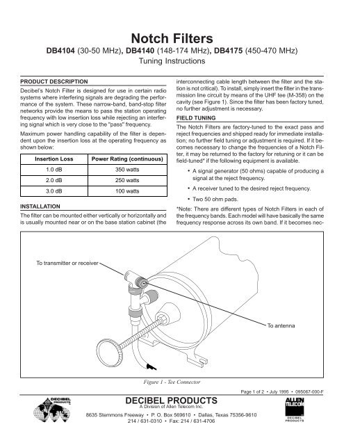
<strong>Notch</strong> <strong>Filters</strong>DB4104 (30-50 MHz), DB4140 (148-174 MHz), DB4175 (450-470 MHz)Tuning InstructionsPRODUCT DESCRIPTIONDecibel’s <strong>Notch</strong> Filter is designed for use in certain radiosystems where interfering signals are degrading the performanceof the system. These narrow-band, band-stop filternetworks provide the means to pass the station operatingfrequency with low insertion loss while rejecting an interferingsignal which is very close to the "pass" frequency.Maximum power handling capability of the filter is dependentupon the insertion loss at the operating frequency asshown below:Insertion LossPower Rating (continuous)1.0 dB 350 watts2.0 dB 250 watts3.0 dB 100 wattsINSTALLATIONThe filter can be mounted either vertically or horizontally andis usually mounted near or on the base station cabinet (theinterconnecting cable length between the filter and the stationis not critical). To install, simply insert the filter in the transmissionline circuit by means of the UHF tee (M-358) on thecavity (see Figure 1). Since the filter has been factory tuned,no further adjustment is necessary.FIELD TUNINGThe <strong>Notch</strong> <strong>Filters</strong> are factory-tuned to the exact pass andreject frequencies and shipped ready for immediate installation;no further field tuning or adjustment is required. If it becomesnecessary to change the frequencies of a <strong>Notch</strong> Filter,it may be returned to the factory for retuning or it can befield-tuned* if the following equipment is available.• A signal generator (50 ohms) capable of producing asignal at the reject frequency.• A receiver tuned to the desired reject frequency.• Two 50 ohm pads.*Note: There are different types of <strong>Notch</strong> <strong>Filters</strong> in each ofthe frequency bands. Each model will have basically the samefrequency response across its own band. If it becomes nec-To transmitter or receiverTo antennaFigure 1 - Tee ConnectorDECIBEL PRODUCTSA Division of Allen Telecom Inc.8635 Stemmons Freeway • P. O. Box 569610 • Dallas, Texas 75356-9610214 / 631-0310 • Fax: 214 / 631-4706Page 1 of 2 • July 1995 • 095067-000-F
DB4104, DB4140, DB4175 <strong>Notch</strong> <strong>Filters</strong>essary to change the frequency response, a different stubharnessconfiguration will be needed.FIELD TUNING PROCEDURE1. Connect equipment as shown in Figure 2.2. Tune the signal generator to the desired reject frequency.3. Tune each cavity for minimum signal into the receiver.(Clockwise on tuning screw decreases resonant frequencyof cavity.)4. Lock tuning screw nut after tuning each cavity.LABORATORY TUNING PROCEDURE1. Connect equipment as shown in Figure 3.2. Connect the 3 dB pads to the <strong>Notch</strong> Filter terminals.3. Tune signal generator to within 1 KHz of the reject frequencyusing the frequency counter.4. Tune the local oscillator 30 MHz below the reject frequencyto obtain a reading on the 30 MHz I.F. amplifier.Add or remove attenuation with the decade attenuatorsuntil I.F. amplifier reads on scale.Decibel Products5. Tune each cavity for a minimum signal into the I.F. amplifier.(Clockwise on tuning screw lowers resonant frequencyof cavity.)6. Set reference reading on I.F. amplifier meter and noteattenuation in decade attenuators.7. Remove <strong>Notch</strong> Filter from setup and connect the 3 dBpads together. Add attenuation in the decade attenuatorsuntil the reference reading on I.F. amplifier isachieved. The difference in the decade attenuation readingsfrom step 6 is the amount of attenuation throughthe filter at the reject frequency.8. Lock tuning screw shaft after tuning each cavity.9. With test equipment tuned to the pass frequency, measureinsertion loss of the filter at the pass frequency.Warning!Installation of this product near electrical power linesis dangerous. For your safety,follow the installation procedures.<strong>Notch</strong>FilterSignalGenerator50 OhmPad< < > >50 OhmPadReceiverFigure 2 - Field Tuning Equipment<strong>Notch</strong>FilterSignalGeneratorCoupler3 dBPad< >3 dBPadDecadeAtten.0-100 dBDecadeAtten.0-10 dBLocalOsc.Freq.Counter30 MHzI.F. Amp.30 MHzMixerFigure 3 - Laboratory Tuning EquipmentDECIBEL PRODUCTSA Division of Allen Telecom Inc.8635 Stemmons Freeway • P. O. Box 569610 • Dallas, Texas 75356-9610214 / 631-0310 • Fax: 214 / 631-4706Page 2 of 2 • July 1995 • 095067-000-F