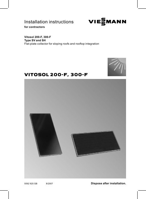
Vitosol 200-F installation instructions - Viessmann
Vitosol 200-F installation instructions - Viessmann
Vitosol 200-F installation instructions - Viessmann

You also want an ePaper? Increase the reach of your titles
YUMPU automatically turns print PDFs into web optimized ePapers that Google loves.
Safety <strong>instructions</strong>Please follow these safety <strong>instructions</strong> closely to prevent accidents andmaterial losses.Safety <strong>instructions</strong> explained!Please noteThis symbol warns against therisk of material losses andenvironmental pollution.NoteDetails identified by the word "Note"contain additional information.Target groupThese <strong>instructions</strong> are exclusivelydesigned for qualified personnel.& Work on gas appliances must onlybe carried out by a qualified gas fitter.& Work on electrical equipment mustonly be carried out by a qualifiedelectrician.Regulations& theCodeofPracticeofrelevanttrade associations,& all current safety regulations asdefined by DIN, EN, DVGW, TRGI,TRF, VDE and all locally applicablestandards.Workingonthesystem& Isolate the system from the powersupply and check that it is no longer'live', e.g. by removing a separatefuse or by means of a mains isolator.& Safeguard the system againstunauthorised reconnection.& When using gas as fuel, also closethe main gas shut‐off valve andsafeguard against unauthorisedreopening.Observe the following when workingon this system& all legal <strong>instructions</strong> regarding theprevention of accidents,& all legal <strong>instructions</strong> regardingenvironmental protection,5592 925 GB2
IndexPreparing for <strong>installation</strong>.......................................................................... 4Installation sequenceRoof tile cover ............................................................................................ 5& Component overview ............................................................................... 5& Fitting the covering frame......................................................................... 8& Collector <strong>installation</strong> ................................................................................ 17& Covering the roof ..................................................................................... 20Slate cover ................................................................................................. 22& Component overview ............................................................................... 22& Fitting the covering frame......................................................................... 24& Collector <strong>installation</strong> ................................................................................ 31& Covering the roof ..................................................................................... 34Plain tile cover ............................................................................................ 35& Component overview ............................................................................... 35& Fitting the covering frame......................................................................... 38& Collector <strong>installation</strong> ................................................................................ 44& Covering the roof ..................................................................................... 47Installing the connection set and collector temperature sensor .................... 49Installation.................................................................................................. 50Commissioning and adjustment .................................................................. 535592 925 GB3
Preparing for <strong>installation</strong>Space requirementType SV3000 mm height and 2100 mmwidth + 1080 mm for each additionalcollectorType SH1700 mm height and 3400 mmwidth + 2400 mm for each additionalcollectorLeave that area free on new buildings.Where roofs are already covered,remove the cover.To prevent damage to the ridge coverand to ensure good ventilation belowthe roof, leave enough room towardsthe ridge.Fit a snow grille above the collectorswhere there is a larger gap betweenthe collectors and the roof ridge.Provide a roof hatch near the collectorsfor inspection and maintenance.Earthing and lightning protection of the solar heating systemCreate an electrically conductive connectionbetween the solar circuit pipeworkand in the lower part of thebuildinginaccordancewithVDE[orlocal] regulations.The connection of the collector systemto a new or existing lightning protectionsystem or the provision oflocal earthing must only be carried outby authorised trained personnel, whomust take into account the conditionsapplicable on site.5592 925 GB4
Roof tile coverComponent overviewType a mm b mm c mm d mm e mmSV1 2829 1526 1363 1076 1078SH1 1505 865 702 2394 23965592 925 GB1 Roof cover frame, l.h. section2 Roof cover frame, lower centresection3 Roof cover frame, upper centresection4 Roof cover frame, r.h. section5 Timber 24 x 48 x 2600 mm6 Wedge strut39 x 120 x 1<strong>200</strong>/2400 mm7 Wire nail8 Retaining plate9 Mounting bracketqP Zinc-plated countersunk chipboardscrew (Spax-s) 4 x 30 mmqQ Butyl stripqW Cover stripqE Special screw 4.5 x 45 mmqR Special screw 4.5 x 35 mmqT Spacer plugqZ Diagonal sealing stripqU Clamping bracket5
Roof tile cover (cont.)qI WasherqO Hexagon nutAccessories for one collector arraywQ Connecting pipeConnection set:wW Connecting pipe (long)wE Connecting pipe (short)wR PlugwT Profile clipwZ Locking ring fitting (elbow 90 °),7 22 mmwU Support sleeveAccessories for one solar heatingsystemSensor well set, comprising:wU Support sleevewI Lockingringfitting(tee), 7 22 mmwO Sensor welleP Strain relief fittingeQ Thermal insulation5592 925 GB6
Roof tile cover (cont.)NoteDeduct dimension x on site.A CollectorB Covering frameC Existing roof battensD TimberE Topedge,frame=topedgetimberF Additional batten (on site),only where tiles do not need to betrimmedG Wedge strutH Lead flashing; must be positionedevenly between the roof coverframe and the tile row (water runoff)5592 925 GBType f mm g mm h mm k mmSV 2380 1439 2541 2748SH 1056 778 1217 14247
Roof tile cover (cont.)Fitting the covering frameType g mm h mm k mmSV 1439 2541 2748SH 778 1217 14241. Remove the protective foil fromthe covering frame.2. Nail the timber and the wedgestrut over the entire width of thecovering frame.NoteMaintainthesideclearancetothecovering frame (to be fitted later)of 250 mm (see the diagram onpage 10).5592 925 GB8
Roof tile cover (cont.)A Edge of cutB L.h. sectionC R.h. section3. Mark dimension x for the tilecover on the upper timber, so thatthe tiles butt onto the l.h. and r.h.section.NoteShould it become necessary totrim the tiles, arrange dimensionsx so that the tiles will be trimmedin front of the corrugation.Type x mmNumber of collectors1 2 3 4 5 6 8 10SV 1382 2466 3550 4634 5718 6802 8970 11138SH 2706 5114 7523 9931 12340 14748 19564 243805592 925 GB9
Roof tile cover (cont.)4. Butt the l.h. section to the upperedge of the timber.5. Provisionally position two tilesandpushthel.h.sectionuptothelarge return edge underneath thetile.Level the section horizontally.NoteNever step onto the coveringframe sections.5592 925 GB10
Roof tile cover (cont.)6. Secure the l.h. section in theupper area of the diagonal sealingstrip (to be fitted later) (see alsothe diagram on page 16) togetherwith the retaining plate, using thescrews provided.7. Secure the side retaining plateswith screws.NoteFor type SV, there is a total of 4retaining plates per side section;for type SH there is a total of 3retaining plates per side section.5592 925 GB11
Roof tile cover (cont.)8. Position the lower centre section,so that the plugs in the side sectionbutt against the centre section.9. Removetheprotectivetapefromthe sealing strip of the mountingbracket.10. Secure the mounting bracket (fortype SH 2bracketssidebyside)with screws in accordance withthe markings.11. Secure the butyl strip.5592 925 GB12
Roof tile cover (cont.)A Press profiles12. Position the upper centre partagainst the press profiles of thelower part.13. Removetheprotectivetapefromthe sealing strip of the mountingbracket.14. Secure the mounting bracket (fortype SH 2bracketssidebyside)with screws in accordance withthe markings.15. Push the upper centre sectionagainst the butyl strip.5592 925 GB13
Roof tile cover (cont.)16. Secure the top of the centre platewith the retaining plate using thescrews provided.18. Secure the spacer plug.19. Fit further centre sections.17. Secure the cover strip withscrewsoverthesideandcentresections.5592 925 GB14
Roof tile cover (cont.)20. Secure the r.h. section like the l.h.section.5592 925 GB15
Roof tile cover (cont.)A Lead flashing21. Affix the diagonal sealing strip tothe external edge of the coveringframe array.& Butt joints should not be locatedat corners.& The vertical side of the stripshould point inwards.& Affix approx. 100 to 150 mm ofthe strip to the lead flashing.5592 925 GB16
Roof tile cover (cont.)Collector <strong>installation</strong>& The side with the type plate must be on the outside of the first and last collector.& Secure the pipework on only one collector opposite the side with the typeplate.1. Position the collector on the mountingbracket and push down with aneven pressure.2. Secure the collector with clampingbrackets to the mounting bracket.5592 925 GB17
Roof tile cover (cont.)3.!Please noteConnecting pipes should notshow any signs of damage.Lubricate all plug-in connectors(O-rings) found on thecollectors only with the specialgrease supplied with theconnection set.Insert the connecting pipes into theflow and return connections.5592 925 GB18
Roof tile cover (cont.)A Type plate4. Position the next collector, so thatthe connecting pipes enter theswaged pipe ends of the former.Secure the collector as describedin points 1 and 2.5592 925 GB19
Roof tile cover (cont.)Covering the roof1. Match the lead flashing to the contoursof the roof tiles and foldtowards the outside at the side sectionsand over onto the lower row oftiles.2. Slightly lift the lead flashing,remove the paper backing from thebutyl strip and lightly press downon the flashing.5592 925 GB20
Roof tile cover (cont.)3. Position the roof tiles and slightlypress the diagonal sealing striptowards the collector.Where necessary, trim the tiles oruse half tiles (see the informationon page 9).Continue with chapter "installing theconnection set and collector temperaturesensor".NoteTrim head tile A that lies on theedge of the lead flashing by knockingoff or grinding off part of the tile.5592 925 GB21
Slate coverComponent overview1 Roof cover frame, l.h. section2 Roof cover frame, lower centresection3 Roof cover frame, upper centresection4 Roof cover frame, r.h. section8 Retaining plate9 Mounting bracketqP Zinc-plated countersunk chipboardscrew (Spax-s) 4 x 30 mmqQ Butyl stripqW Cover stripqE Special screw 4.5 x 45 mmqR Special screw 4.5 x 35 mmqT Spacer plugqZ Diagonal sealing stripqU Clamping bracketqI WasherqO Hexagon nut5592 925 GB22
Slate cover (cont.)Accessories for one collector arraywQ Connecting pipeConnection set:wW Connecting pipe (long)wE Connecting pipe (short)wR PlugwT Profile clipwZ Locking ring fitting (elbow 90 °),7 22 mmwU Support sleeveAccessories for one solar heatingsystemSensor well set, comprising:wU Support sleevewI Lockingringfitting(tee), 7 22 mmwO Sensor welleP Strain relief fittingeQ Thermal insulation5592 925 GB23
Slate cover (cont.)A Lead flashing; must be positionedlevel between the roof coverframe and the slate (water run-off)B Covering frameC CollectorFitting the covering frame1. Remove the protective foil fromthe covering frame.5592 925 GB24
Slate cover (cont.)2. Level the l.h. section with a spiritlevel and secure at the top in thearea of the diagonal sealing strip(to be affixed later) (see also thediagram on page 30) togetherwith the retaining plate.3. Secure the side retaining plateswith screws.NoteNever step onto the coveringframe sections.5592 925 GB25
Slate cover (cont.)4. Position the lower centre section,so that the plugs in the side sectionbutt against the centre section.6. Secure the mounting bracket inaccordance with the markings.7. Secure the butyl strip.5. Removetheprotectivetapefromthe sealing strip of the mountingbracket.5592 925 GB26
Slate cover (cont.)A Press profiles8. Position the upper centre partagainst the press profiles of thelower part.9. Removetheprotectivetapefromthe sealing strip of the mountingbracket.10. Secure the mounting bracket inaccordance with the markings.11. Push the upper centre sectionagainst the butyl strip.5592 925 GB27
Slate cover (cont.)12. Secure the top of the centre platewith the retaining plate using thescrews provided.14. Secure the spacer plug.15. Fit further centre sections.13. Secure the cover strip withscrewsoverthesideandcentresections.5592 925 GB28
Slate cover (cont.)16. Secure the r.h. section like the l.h.section.5592 925 GB29
Slate cover (cont.)A Lead flashing17. Affix the diagonal sealing strip tothe external edge of the coveringframe array.& Butt joints should not be locatedat corners.& The vertical side of the stripshould point inwards.& Affix approx. 100 to 150 mm ofthe strip to the lead flashing.5592 925 GB30
Slate cover (cont.)Collector <strong>installation</strong>& The side with the type plate must be on the outside of the first and last collector.& Secure the pipework on only one collector opposite the side with the typeplate.1. Position the collector on the mountingbracket and push down with aneven pressure.2. Secure the collector with clampingbrackets to the mounting bracket.5592 925 GB31
Slate cover (cont.)3.!Please noteConnecting pipes should notshow any signs of damage.Lubricate all plug-in connectors(O-rings) found on thecollectors only with the specialgrease supplied with theconnection set.Insert the connecting pipes into theflow and return connections.5592 925 GB32
Slate cover (cont.)A Type plate4. Position the next collector, so thatthe connecting pipes enter theswaged pipe ends of the former.Secure the collector as describedin points 1 and 2.5592 925 GB33
Slate cover (cont.)Covering the roof1. Match the lead flashing to the contoursof the slate and fold over theoutsideofbothsidesections.2. Slightly lift the lead flashing,remove the paper backing from thebutyl strip and lightly press downon the flashing.3. Position the slate up to the centreedge of the side section; during theapplication, press the diagonalsealing strip slightly against thecollector.Continue with chapter "installing theconnection set and collector temperaturesensor".5592 925 GB34
Plain tile coverComponent overview1 Roof cover frame, l.h. section2 Roof cover frame, lower centresection3 Roof cover frame, upper centresection4 Roof cover frame, r.h. section5 Timber 24 x 48 x 2600 mm6 Wedge strut40 x 45 x 1<strong>200</strong>/2400 mm7 Wire nail8 Retaining plate9 Mounting bracketqP Zinc-plated countersunk chipboardscrew (Spax-s) 4 x 30 mmqQ Butyl stripqW Cover stripqE Special screw 4.5 x 45 mmqR Special screw 4.5 x 35 mmqT Spacer plugqZ Diagonal sealing stripqU Clamping bracketqI WasherqO Hexagon nutwP Nocky panel5592 925 GB35
Plain tile cover (cont.)Accessories for one collector arraywQ Connecting pipeConnection set:wW Connecting pipe (long)wE Connecting pipe (short)wR PlugwT Profile clipwZ Locking ring fitting (elbow 90 °),7 22 mmwU Support sleeveAccessories for one solar heatingsystemSensor well set, comprising:wU Support sleevewI Lockingringfitting(tee), 7 22 mmwO Sensor welleP Strain relief fittingeQ Thermal insulation5592 925 GB36
Plain tile cover (cont.)A CollectorB Covering frameC Existing roof battensD TimberE Topedge,frame=topedgetimberF Wedge strutG Lead flashing; must be positionedevenly between the roof coverframe and the tile row (water runoff)5592 925 GB37
Plain tile cover (cont.)Fitting the covering frame1. Remove the protective foil fromthe covering frame.2. Nail the timber and the wedgestrut over the entire width of thecovering frame.A Edge of cutB L.h. sectionC R.h. section3. Mark dimension x for the tilecover on the upper timber, so thatthe tiles butt onto the l.h. and r.h.section.5592 925 GB38
Plain tile cover (cont.)xmmNumber of collectors1 2 3 4 5 6 8 101348 2432 3516 4600 5684 6768 8936 111044. Butt the l.h. side section to theupper edge of the timber and levelusing a spirit level.NoteNever step onto the coveringframe sections.5. Secure the l.h. section in theupper area of the diagonal sealingstrip (to be fitted later) (see alsothe diagram on page 43) togetherwith the retaining plate, using thescrews provided.5592 925 GB39
Plain tile cover (cont.)6. Position the lower centre section,so that the plugs in the side sectionbutt against the centre section.8. Secure the mounting bracket inaccordance with the markings.9. Secure the butyl strip.7. Removetheprotectivetapefromthe sealing strip of the mountingbracket.5592 925 GB40
Plain tile cover (cont.)A Press profiles10. Position the upper centre partagainst the press profiles of thelower part.11. Removetheprotectivetapefromthe sealing strip of the mountingbracket.12. Secure the mounting bracket inaccordance with the markings.13. Push the upper centre sectionagainst the butyl strip.5592 925 GB41
Plain tile cover (cont.)14. Secure the top of the centre platewith the retaining plate using thescrews provided.16. Secure the spacer plug.17. Fit further centre sections.15. Secure the cover strip withscrewsoverthesideandcentresections.5592 925 GB42
Plain tile cover (cont.)18. Secure the r.h. section like the l.h.section.5592 925 GB43
Plain tile cover (cont.)19. Affix the diagonal sealing strip atthe top of the external edge of thecovering frame array.Theverticalsideofthestripshould point inwards.Collector <strong>installation</strong>& The side with the type plate must be on the outside of the first and last collector.& Secure the pipework on only one collector opposite the side with the typeplate.1. Position the collector on the mountingbracket and push down with aneven pressure.2. Secure the collector with clampingbrackets to the mounting bracket.5592 925 GB44
Plain tile cover (cont.)3.!Please noteConnecting pipes should notshow any signs of damage.Lubricate all plug-in connectors(O-rings) found on thecollectors only with the specialgrease supplied with theconnection set.Insert the connecting pipes into theflow and return connections.5592 925 GB45
Plain tile cover (cont.)A Type plate4. Position the next collector, so thatthe connecting pipes enter theswaged pipe ends of the former.Secure the collector as describedin points 1 and 2.5592 925 GB46
Plain tile cover (cont.)Covering the roof1. Match the lead flashing to the contoursof the roof tiles and fold overthe outside of both side sectionsand over onto the lower row of tiles.2. Slightly lift the lead flashing,remove the paper backing from thebutyl strip and lightly press downon the flashing.5592 925 GB47
Plain tile cover (cont.)3. Startatthebottom.Hook in the tiles and position theNocky panel on the tile.4. Hook the next tile into the battenand position the Nocky panel onthe tile. When doing this ensurethat the panels overlap.5. Trim the final Nocky panel to theshape of the side panel and position.6. Bend the return of the side panelover all Nocky panels.NoteRepeat this process until the penultimateNocky panel.5592 925 GB48
Installing the connection set and collector temperature sensorObserve the following when installingthe locking ring fitting:& All pipes must be cut at a right angleand deburred.& Push the union nut and the lockingring onto the pipe and lightly lubricatethe threads with oil.& Pushthepipeintothelockingringfitting as far as it will go.& Initially turn the union nut by hand,thentightenwithanopenendedspanner by a further ¾ turn.Never fit annealed copper pipes ontothe locking ring fittings.5592 925 GBA Flow connectionB Return connectionC Swaged connectionD Type plate49
Installing the connection set and collector . . . (cont.)1. Insert the plug as far as possible,then secure it with hose clips.2. Insert the connecting pipes as faras possible, then secure them withprofile clips.3. Fit the elbow to the return connector.4. Fit the tee onto the flow connector.5. Insert the sensor well into the tee,counterholding the tee.6. Insert the strain relief fitting into thesensor well.7. Insert the collector temperaturesensor as far as possible into thesensor well and secure with strainrelief fitting.8. Insert the support sleeves into theconnecting pipes of the solar circuit.Make the connection between thecollector array and pipework of thesolar heating circuit.9. Fit the thermal insulation and joinits cut faces with adhesive.!Please noteThe collectors may bedamaged if the solar heatingsystem is not filled with heattransfer medium immediatelyafter <strong>installation</strong>.Therefore, protect the collectorsagainst solar irradiationby covering them up.Installation!Please noteIncorrect <strong>installation</strong> can lead to collector damage.Use only gunmetal or brass fittings and copper pipes for the <strong>installation</strong>.Use hemp only in conjunction with pressure and temperature-resistantsealants (e.g. Viscotex Solarpaste from Locher, CH-9450 Altstätten,Switzerland).Never step onto solar panels.Never solder near or on the collector.5592 925 GB50
Installation (cont.)1. Position pipes so that completeventilation is guaranteed. Werecommend the <strong>installation</strong> of anair vent valve with shut-off facilityat the highest point of the system.Install an air separator at an accessiblepoint in the pipework (see thefollowing diagram).2. Equip systems to EN 12975 withexpansion vessel, safety valve andcirculation pump.3. The expansion vessel must beapproved to DIN 4807 [or local regulations]and must be installed witha thermal insulating loop. The diaphragmsand seals of the expansionvessel and the safety valvemust be suitable for the heat transfermedium.For the calculation of theinlet pressure, see the"<strong>Vitosol</strong>" service <strong>instructions</strong>.4. When operating without Solar-Divicon,only use safety valvesdesigned for 120 °C, a max. pressureof 6 bar, which carry the "S"(Solar) designation.5. Make all connections pressure andtemperature-resistant (observe themax. idle temperature of the collector).5592 925 GB51
Installation (cont.)A CollectorB Solar-DiviconC Drip containerD Expansion vesselE Pre-cooling vesselF Shut-off valveG Filling facilityH Manual solar fill pumpK Fill valve (F, G, L)L DrainM Air separatorN DHW cylinderO Solar control unitP Air vent valve5592 925 GB52
Commissioning and adjustmentService <strong>instructions</strong> "<strong>Vitosol</strong>-F"5592 925 GB53
545592 925 GB
5592 925 GB55
Printed on environmentally friendly,chlorine-free bleached paper<strong>Viessmann</strong> Werke GmbH&Co KGD-35107 AllendorfTelephone: +49 6452 70-0Fax: +49 6452 70-2780www.viessmann.com<strong>Viessmann</strong> LimitedHortonwood 30, TelfordShropshire, TF1 7YP, GBTelephone: +44 1952 675000Fax: +44 1952 675040E-mail: info-uk@viessmann.com5592 925 GB Subject to technical modifications.56