radiance 100mbps single interface line cards
radiance 100mbps single interface line cards
radiance 100mbps single interface line cards

Create successful ePaper yourself
Turn your PDF publications into a flip-book with our unique Google optimized e-Paper software.
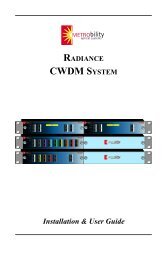
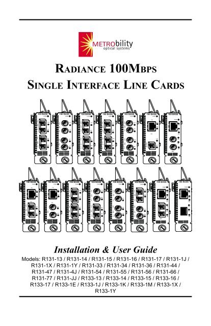
RADIANCE 100MBPSSINGLE INTERFACE LINE CARDS100 BASEPWR100 BASEPWR100 BASEPWR100 BASEPWR100 BASEPWR100 BASEPWR100 BASERXMMTXLKATRXSMTXLKATRXLHTXLKATRXSMTXLKATRXMMTXLKATTXLKATTXPWRLKATFXFDRXMMTXLKATRXSMTXLKATRXLHTXLKATRXELHTXLKATRXMMTXLKATBWDMLKATLKATLBMM100 BASEPWR100 BASEPWR100 BASEPWR100 BASEPWR100 BASEPWR100 BASEPWR100 BASE100 BASETXTXPWRPWRFXLKATTXFXLKATRXMMTXLKATRXMMTXLKATRXMMTXLKATRXMMTXLKATTXLKATFDTXLKATFDRXSMTXLKATMMLKATRXSMTXLKATRXSMTXLKATRXSMTXLKATRXSMTXLKATLKATLBLKATLBSMInstallation & User GuideModels: R131-13 / R131-14 / R131-15 / R131-16 / R131-17 / R131-1J /R131-1X / R131-1Y / R131-33 / R131-34 / R131-36 / R131-44 /R131-47 / R131-4J / R131-54 / R131-55 / R131-56 / R131-66 /R131-77 / R131-JJ / R133-13 / R133-14 / R133-15 / R133-16 /R133-17 / R133-1E / R133-1J / R133-1K / R133-1M / R133-1X /R133-1Y
Radiance 100Mbps Single Interface Line CardsFull-Featured Copper to Fiber with LLCF, FEF, Remote Loopback, Auto-Negotiation, and Auto-Crossover:R133-13 ___ RJ-45 to FX multimode SCR133-14 ___ RJ-45 to FX <strong>single</strong>mode SCR133-15 ___ RJ-45 to FX multimode STR133-16 ___ RJ-45 to FX <strong>single</strong>mode STR133-17 ___ RJ-45 to FX <strong>single</strong>mode SC (40km)R133-1E ___ RJ-45 to FX multimode MT-RJR133-1J ___ RJ-45 to FX <strong>single</strong>mode SC (100km)R133-1K ___ RJ-45 to FX multimode LCR133-1M __ RJ-45 to FX <strong>single</strong>mode LCR133-1X ___ RJ-45 to FX <strong>single</strong>mode SC 1550/1310nm bidirectionalwavelength division multiplexed (BWDM)R133-1Y ___ RJ-45 to FX <strong>single</strong>mode SC 1310/1550nm BWDMCopper to Fiber with LLCF:R131-13 ___ RJ-45 to FX multimode SCR131-14 ___ RJ-45 to FX <strong>single</strong>mode SCR131-15 ___ RJ-45 to FX multimode STR131-16 ___ RJ-45 to FX <strong>single</strong>mode STR131-17 ___ RJ-45 to FX <strong>single</strong>mode SC (40km)R131-1J ___ RJ-45 to FX <strong>single</strong>mode SC (100km)R131-1X ___ RJ-45 to FX <strong>single</strong>mode SC 1550/1310nm BWDMR131-1Y ___ RJ-45 to FX <strong>single</strong>mode SC 1310/1550nm BWDMFiber to Fiber with LLCF:R131-33 ___ FX multimode SC to FX multimode SCR131-34 ___ FX multimode SC to FX <strong>single</strong>mode SCR131-36 ___ FX multimode SC to FX <strong>single</strong>mode STR131-44 ___ FX <strong>single</strong>mode SC to FX <strong>single</strong>mode SCR131-47 ___ FX <strong>single</strong>mode SC to FX <strong>single</strong>mode SC (40km)R131-4J ___ FX <strong>single</strong>mode SC to FX <strong>single</strong>mode SC (100km)R131-54 ___ FX multimode ST to FX <strong>single</strong>mode SCR131-55 ___ FX multimode ST to FX multimode STR131-56 ___ FX multimode ST to FX <strong>single</strong>mode STR131-66 ___ FX <strong>single</strong>mode ST to FX <strong>single</strong>mode STR131-77 ___ FX <strong>single</strong>mode SC (40km) to FX <strong>single</strong>mode SC (40km)R131-JJ ___ FX <strong>single</strong>mode SC (100km) to FX <strong>single</strong>mode SC (100km)This publication is protected by the copyright laws of the United States and other countries, with all rightsreserved. No part of this publication may be reproduced, stored in a retrieval system, translated,transcribed, or transmitted, in any form, or by any means manual, electric, electronic, electromagnetic,mechanical, chemical, optical or otherwise, without prior explicit written permission of Metrobility OpticalSystems, Inc.© 2001-2004 Metrobility Optical Systems, Inc. All rights reserved. Printed in USA.
Table of ContentsRadiance 100Mbps Single Interface Line CardsInstallation & User GuideOverview .............................................................................................................. 4Installation Guide ............................................................................................... 5STEP 1: Unpack the Line Card ............................................................. 5STEP 2: Set the Jumper (R131 Only) ................................................... 5STEP 3: Set the MDI-II/MDI-X Switch(R131-1x twisted-pair ports only) .......................................... 6STEP 4: Set the DIP Switches (R133 Only) ......................................... 7STEP 5: Install the Line Card ............................................................... 9STEP 6: Connect to the Network ........................................................ 10User Guide ........................................................................................................ 13LED Indicators .................................................................................... 13Link Loss Carry Forward (LLCF) ...................................................... 14Far End Fault (FEF—R133 Only) ...................................................... 16Remote Loopback (R133 Only) .......................................................... 17Topology Solutions ............................................................................. 18Technical Specifications...................................................................... 19Product Safety, EMC and Compliance Statements ............................. 21Warranty and Servicing ....................................................................... 22Metrobility, Metrobility Optical Systems, and NetBeacon are trademarks of Metrobility Optical Systems,Inc. The Metrobility Optical Systems logo is a trademark of Metrobility Optical Systems, Inc. All othersare trademarks of their respective owners.The information contained in this document is assumed to be correct and current. The manufacturer isnot responsible for errors or omissions and reserves the right to change specifications at any timewithout notice.
OverviewFor updating or expanding an existing network, Metrobility® offers theRadiance 100Mbps <strong>single</strong> <strong>interface</strong> <strong>line</strong> <strong>cards</strong> in various combinations includingcopper to fiber, multimode to <strong>single</strong>mode, and fiber optic distance extension.Use the optical extender units to increase your network reach up to 100km over<strong>single</strong>mode cables at full duplex without the need for repeaters. These <strong>line</strong> <strong>cards</strong>allow you to maximize your Fast Ethernet segments and transparently transmitall signal activity for multimode-to-multimode or <strong>single</strong>mode-to-<strong>single</strong>modeconfigurations.The mixed-media <strong>line</strong> <strong>cards</strong> offer seamless integration of copper and fiber connectionsin copper-to-fiber networks. This innovative solution provides full signalrestoration ensuring accurate data transmission and guaranteeing maximum cablelength support. All <strong>line</strong> <strong>cards</strong> are compatible with any Fast Ethernet device.Through Metrobility’s unique management functionality, you can manageremote connections through console commands, our NetBeacon ® or WebBeaconsoftware, or with any standard SNMP application. This end-to-end visibility ofyour network not only simplifies network management but also increasesnetwork reliability.The Radiance 100Mbps <strong>line</strong> card provides the following key features:• Fused power on each <strong>line</strong> card to protect the rest of the <strong>cards</strong> in thechassis from a short circuit. The power (PWR) LED on an affected cardwill not be lit if its fuse is blown.• Half and full duplex support.• Auto polarity support on all twisted-pair ports.• Link Loss Carry Forward functionality to aid in troubleshooting.• MDI-II/MDI-X switch on all R131 twisted-pair ports. The R133 providesbuilt-in crossover to automatically perform the function of the switch.• On the R133, the copper port supports auto-negotiation and the fiber portsupports both Far End Fault (FEF) and remote loopback.• Data frame size transparency.• Numerous connectivity options, including bidirectional wavelengthmultiplexed (BWDM) fiber.4
Installation GuideFollow the simple steps out<strong>line</strong>d in this section to install and start using theRadiance 100Mbps <strong>single</strong> <strong>interface</strong> <strong>line</strong> card.NOTE: Electrostatic discharge precautions should be taken when handling any<strong>line</strong> card. Proper grounding is recommended (i.e., wear a wrist strap).1Unpack the Line CardYour order has been provided with the safest possible packaging, butshipping damage does occasionally occur. Inspect your <strong>line</strong> cardcarefully. If you discover any shipping damage, notify your carrier andfollow their instructions for damage and claims. Save the originalshipping carton if return or storage of the unit is necessary.2Set the Jumper (R131 Only)All Radiance 100Mbps <strong>single</strong> <strong>interface</strong> <strong>line</strong> <strong>cards</strong> incorporate LLCF(Link Loss Carry Forward) functionality as an aid in troubleshooting aremote connection. A jumper configures LLCF * operation on the R131models.Jumper SettingsSee the diagram below for the location of the LLCF jumper.• Connect pins 1 and 2 to enable LLCF.• Connect pins 2 and 3 to disable LLCF. (default)LLCF3 OFF21 ONLLCFJumperPort 1This is a generalized diagram of a Radiance R131100Mbps <strong>single</strong> <strong>interface</strong> <strong>line</strong> card and is not specific toany particular model.Port 2*LLCF also can be controlled through console commands or with Metrobility’s NetBeacon or WebBeacon managementsoftware. Refer to the Command Line Interface Reference Guide, NetBeacon Element Management Software Installation& User’s Guide or WebBeacon Management Software Installation & User’s Guide for software management information.Radiance 100Mbps Single Interface Line Cards 5
3Set the MDI-II/MDI-X Switch(R131-1x twisted-pair ports only)To eliminate the need for crossover cables, the R131-1x <strong>line</strong> card hasan MDI-II to MDI-X slide switch for its twisted-pair port. The switch ispositioned directly behind its associated RJ-45 connector and allowssimple setup in either straight-through (default) or crossover configurations.See the diagram below for the location of the switch.3 OFF21 ONLLCFMDI-X PositionSlide SwitchRJ-45MDI-II Position (default)When setting the MDI-II to MDI-X switch, observe the positioning ofthe following symbols:• The parallel symbol (II) indicates a straight-through or parallelconnection. (default)• The cross symbol (X) indicates a crossover connection.These symbols are clearly marked on the printed circuit board. Simplyslide the switch in the direction of the appropriate symbol. Use thefollowing table as a guide.A device that is wired straight through needs one crossover connection:If the cable isthe MDI-II to MDI-X Switch Setting should bestraight throughXcrossoverIIA device that is wired crossover needs a parallel connection:If the cable isthe MDI-II to MDI-X Switch Setting should bestraight throughIIcrossoverX6 Installation Guide
4Set the DIP Switches (R133 only)The R133 provides a set of six DIP switches located on the back of theboard. These switches allow you to select from several modes ofoperation. To enable a function, set the switch UP (lever pushed awayfrom the printed circuit board); to disable a function, set the switchDOWN (lever pushed toward the circuit board). The default settings areshown below.DefaultL D LCF F A F SLBREF N1 D1LBKDIP SwitchSettingsIOI=ONO = OFFLink Loss Carry Forward Switch (LLCF)The R133 incorporates Link Loss Carry Forward functionality as an aidin troubleshooting remote connections. When LLCF is enabled, the lossof inbound link pulses on a port stops the transmission of outbound linkpulses from the opposite port. For example, if LLCF is enabled, the lossof incoming link pulses at Port 1 will stop the transmission of linkpulses out of Port 2. Conversely, if Port 2 stops receiving link pulses,Port 1 will not transmit link pulses.Link Loss Carry Forward is enabled simultaneously on both ports whenswitch LLCF is enabled. The unit is shipped with LLCF disabled. Referto Link Loss Carry Forward in the User Guide section of this manualfor further details.Far End Fault Switch (FEF)The R133 supports Far End Fault functionality to detect the loss of linkby the remote unit’s fiber port receiver.FEF is only applicable to the fiber port (Port 2). When FEF is enabledon a port, the loss of the inbound link pulses on that port generates analarm, which is sent out the port’s transmitter. FEF also enables a portto read the alarm. To function properly, the FEF setting on both thelocal and remote R133 <strong>line</strong> <strong>cards</strong> must be the same.For example, if FEF is enabled on both <strong>line</strong> <strong>cards</strong> and the remote unit’sfiber receiver (RX) stops detecting link pulses, then its fiber transmitter(TX) will send an alarm. The local <strong>line</strong> card will receive the alarm andreport it through its fiber port FEF LED, which will turn amber. NoRadiance 100Mbps Single Interface Line Cards 7
alarm will be issued if FEF is disabled on the remote card. The FEFLED will not turn amber if FEF is disabled on the local R133 <strong>line</strong> cardbecause it will not be able to detect the alarm.Far End Fault is enabled on Port 2 when switch FEF is ON. The unit isshipped with FEF disabled. Refer to Far End Fault in the User Guidesection of this manual for more information.Auto-Negotiation Switch (AN1)Switch AN1 controls the use of auto-negotiation on the copper port.Auto-negotiation determines whether the port operates at half or fullduplex. When AN1 is enabled, the copper port advertises full duplexcapabilities to its connected device, if the duplex switch, FD1, isenabled. The port will advertise half duplex capabilities if FD1 isdisabled. If AN1 is disabled, the duplex switch will determine the port’sduplex mode. By default, auto-negotiation is enabled.Duplex Switch (FD1)Switch FD1 sets the duplex mode for the copper port when autonegotiationis disabled. The port operates at full duplex when FD1 isenabled; and it operates at half duplex when FD1 is disabled. If autonegotiationis enabled, the FD1 switch setting will determine whetherthe port advertises full or half duplex (refer to Auto-Negotiation above).The default is set to full duplex enabled.Copper Port Configuration TableUse the table below to set the duplex and auto-negotiation DIPswitches to obtain specific modes of operation for the copper port.CopperPort Configuration FD1AN1FullDuplexHalfDuplexAuto-NegotiateFull DuplexAuto-NegotiateHalf DuplexONOFFONOFFOFFOFFDisable Loopback Switch (DSLB)This switch determines the response of the fiber port when it receivesthe remote loopback command. If the DSLB switch is enabled, the portwill ignore all remote loopback commands. When the switch isdisabled, the port will permit remote loopback to occur. By default, theresponse switch is disabled, which allows remote loopback.ONON8 Installation Guide
TXxIIxIITXPWR100 FD100 FDRXLKTXRXLKTXMMxIITXFLPWR100 FDRXLKTXRXLKTXTXxIIMMPWR100 FDRXFXLKTXRXLKTXPWR100 FDRRX LKXTXMMLKTXxIITXRXMSMTXFXLKRXLKTXMMSMSXLXPWRLKLKMMRXSMTXSXLXPWRLKLKRXMMTXRXSMTXPWRLKLKMMMMFLPWRFXRXTTXXRXLKTX TXRXLKTXFXMMPWRMMLKATLKATFLFXPWRRXLKTXRXLKTXMMMMFLFXPWRRXLKTXRXLKTXMMMMFLFXPWRRXLKTXRXLKTXRXMMTXRXSMTXPWRLKLKRXMMTXRXSMTXPWRLKLKRXMMTXRXSMTXPWRLKLKRemote Loopback Switch (RLBK)The remote loopback switch allows you to test the fiber connectionbetween two Metrobility x133 units. Enabling the switch sends aloopback request to the remote fiber port. To run the remote loopbacktest properly, the following conditions must be met:• The remote unit must be a Metrobility x133. The remote unitmay be either a standalone converter or <strong>line</strong> card.• The DSLB response switch on the remote unit must be disabled.If the conditions are satisfied, the remote loopback sequence will begin.The remote fiber port will go into loopback mode. Next, the local cardwill generate a test pattern that is sent to the remote unit and thenlooped back. The local card will read the returned data to verify propertransmission. The LB LED on the local card will indicate whether thetest passed (green) or failed (amber). Refer to Remote Loopback forfurther information.If the conditions for remote loopback are not met, the remote loopbacktest will always fail. By default, remote loopback is disabled.5Install the Line CardThe Radiance 100Mbps <strong>single</strong> <strong>interface</strong> <strong>line</strong> card offers the ease ofplug-and-play installation and is hot-swappable. The card must befirmly secured to the chassis before network connections are made.Follow the simple steps out<strong>line</strong>d below to install your <strong>line</strong> card.• Grasp the card by the front panel as shown.Card GuideSlot for Management Card10/10010/10010/10010/100 OC-121000BASE1000BASEOC-1210/10010/10010/10010/100OC-12OC-12OC-12MGT-10LK100 BASETPCONSOLEATPWRABRERIMPORTANT! Thumb ScrewTighten thumb screwCard Guideto secure each card firmlyto chassis before makingBlank Panelnetwork connections.Radiance 100Mbps Single Interface Line Cards 9
xIIBWDMTXPWRRXLKTXMMxIITXFLPWR100 FDRXLKTXRXLKTXTXPWRLKATFDLKATLBTXxIIMMPWR100 FDRXFXLKTXRXLKTXRXMMTXTXFXPWRLKATLKATTXxIIMMPWR100 FDRXFXLKTXRXLKTXRXSMTXPWRTX FDRXFXLKATTXxIIMMPWR100 FDRXFXLKTXRXLKTXTXxIIMMPWR100 FDRXFXLKTXRXLKTXMMTXSMPWRATLKRXLKTXMMMMFLFXPWRRXLKTXRXLKTXTXxIIMMPWR100 FDRXFXLKTXRXLKTXTXxIIMMPWR100 FDRXFXLKTXRXLKTXRXMMTXRXMMTXPWRLKATLKATMMMMFLFXPWRRXLKTXRXLKTXTXxIIMMPWR100 FDRXFXLKTXRXLKTX• Insert the card into a slot on the chassis making sure that the topand bottom edges of the board are aligned with the top andbottom card guides in the chassis. Do not force the card into thechassis unnecessarily. It should slide in easily and evenly.• Slide the card in until the top and bottom edges of the frontpanel are flush and even with the top and bottom edges of thechassis.• To secure the <strong>line</strong> card to the chassis, turn the thumbscrewclockwise until it is snug. The card is now properly installed andready for connection to the network.6Connect to the NetworkTo connect the Radiance <strong>line</strong> card to the network, insert the cables intothe appropriate connectors as illustrated below. Be sure the card issecured to the chassis before making network connections. Once poweris applied to the unit, correct connectivity can be verified via the LK(link) LED.100 BASE10/100100 BASE10/100100 BASE10/100100 BASE10/10010/100100 BASE10/10010/10010/100100 BASE10/10010/100MGT-10RXTPLKATRXTXCONSOLEPWRABRERTwisted-Pair InterfacesAll twisted-pair ports provide a shielded RJ-45 connector that supportsa maximum segment length of 100 meters. Use only Category 5 cables.Fiber Optic InterfacesWhen making network connections, make sure that the transmit (TX)port of the card connects to the receive (RX) port of the connecteddevice. Be sure that the transmit (TX) port of the connected deviceconnects to the receive (RX) port of the card.10 Installation Guide
All multimode (MM) fiber optic <strong>interface</strong>s support a maximumsegment length of 2km for remote links.The <strong>single</strong>mode (SM) <strong>interface</strong> supports a maximum segment length of20km, 40km, or 100km. Refer to the Network Connections list belowfor the maximum cable length supported by each model number.BWDM InterfacesThe bidirectional wavelength division multiplexed (BWDM) portprovides one <strong>single</strong>mode SC connector that supports a maximumsegment length of 20km. BWDM <strong>line</strong> <strong>cards</strong> must always be used incomplementary pairs. That is, a -1X model must always be connectedto a -1Y. The -1X <strong>cards</strong> are designed to transmit data at a wavelength of1550nm and receive at 1310nm. Correspondingly, the -1Y <strong>cards</strong>transmit data at 1310nm and receive at 1550nm.Network ConnectionsTX-to-FX:Max DistanceR131-13 RJ-45 to FX multimode SC _________________ 100m/2kmR131-14 RJ-45 to FX <strong>single</strong>mode SC________________ 100m/20kmR131-15 RJ-45 to FX multimode ST _________________ 100m/2kmR131-16 RJ-45 to FX <strong>single</strong>mode ST ________________ 100m/20kmR131-17 RJ-45 to FX <strong>single</strong>mode SC________________ 100m/40kmR131-1J RJ-45 to FX <strong>single</strong>mode SC _______________ 100m/100kmR131-1X RJ-45 to FX <strong>single</strong>mode BWDM SC _________ 100m/20kmR131-1Y RJ-45 to FX <strong>single</strong>mode BWDM SC _________ 100m/20kmR133-13 RJ-45 to FX multimode SC _________________ 100m/2kmR133-14 RJ-45 to FX <strong>single</strong>mode SC________________ 100m/20kmR133-15 RJ-45 to FX multimode ST _________________ 100m/2kmR133-16 RJ-45 to FX <strong>single</strong>mode ST ________________ 100m/20kmR133-17 RJ-45 to FX <strong>single</strong>mode SC________________ 100m/40kmR133-1E RJ-45 to FX multimode MT-RJ ______________ 100m/2kmR133-1J RJ-45 to FX <strong>single</strong>mode SC _______________ 100m/100kmR133-1K RJ-45 to FX multimode LC_________________ 100m/2kmR133-1M RJ-45 to FX <strong>single</strong>mode LC _______________ 100m/20kmR133-1X RJ-45 to FX <strong>single</strong>mode BWDM SC _________ 100m/20kmR133-1Y RJ-45 to FX <strong>single</strong>mode BWDM SC _________ 100m/20kmMM-to-MM:R131-33 FX multimode SC to FX multimode SC ________ 2km/2kmR131-55 FX multimode ST to FX multimode ST ________ 2km/2kmRadiance 100Mbps Single Interface Line Cards 11
MM-to-SM:R131-34 FX multimode SC to FX <strong>single</strong>mode SC _______ 2km/20kmR131-36 FX multimode SC to FX <strong>single</strong>mode ST _______ 2km/20kmR131-54 FX multimode ST to FX <strong>single</strong>mode SC _______ 2km/20kmR131-56 FX multimode ST to FX <strong>single</strong>mode ST _______ 2km/20kmSM-to-SM:R131-44 FX <strong>single</strong>mode SC to FX <strong>single</strong>mode SC _____ 20km/20kmR131-47 FX <strong>single</strong>mode SC to FX <strong>single</strong>mode SC _____ 20km/40kmR131-4J FX <strong>single</strong>mode SC to FX <strong>single</strong>mode SC ____ 20km/100kmR131-66 FX <strong>single</strong>mode ST to FX <strong>single</strong>mode ST _____ 20km/20kmR131-77 FX <strong>single</strong>mode SC to FX <strong>single</strong>mode SC _____ 40km/40kmR131-JJ FX <strong>single</strong>mode SC to FX <strong>single</strong>mode SC____ 100km/100km12 Installation Guide
User GuideThis section contains information about the operating features of theRadiance 100Mbps <strong>single</strong> <strong>interface</strong> <strong>line</strong> <strong>cards</strong>.LED IndicatorsThe Radiance 100Mbps <strong>single</strong> <strong>interface</strong> <strong>line</strong> <strong>cards</strong> provide several LEDs for thevisible verification of unit status and proper functionality. These LEDs can helpwith troubleshooting and overall network diagnosis and management. There areseparate activity (AT) and link (LK) indicators for each port. Once power isapplied to the card, verify correct connectivity via the LK LED.R131 LEDsLEDLabelPWRLEDN ame Color (Status)p owerg reen (steady)The unit is ON.IndicationLKATl inkg reen (steady)Verifies that the port has link established.a ctivityg reen (flashing)The port is receiving data.R133 LEDsLEDLabelLEDN ame Color (Status)IndicationPWRp owerg reen (steady)The unit is ON.Copper Port LEDsLKATl inkg reen (steady)Verifies that the port has link established.a ctivityg reen (flashing)The port is receiving data.FDd uplexgreen (steady)The port is in full-duplex modeduplex mode when not lit.when lit. It is in half-Fiber Port LEDsLKlinkg reen (steady) Verifies that the port has link established.amber (steady)Far end fault detected. The remote fiber portreceiving a valid signal from the local unit.is notATa ctivityg reen (flashing)The port is receiving data.LBremoteloopbackgreen (steady)amber (steady)Remote loopback test was successful; OR on theremote card, fiber port is receiving test pattern.Remote loopback test has failed; OR on the remotecard, fiber port is not receiving test pattern.o ffNormal operation.Radiance 100Mbps Single Interface Line Cards 13
Link Loss Carry Forward (LLCF) *The Radiance 100Mbps <strong>single</strong> <strong>interface</strong> <strong>line</strong> <strong>cards</strong> incorporate an LLCF functionfor troubleshooting a remote connection. When LLCF is enabled, the ports donot transmit a link signal until they receive a link signal from the opposite port.The diagram below shows a typical network configuration with a good linkstatus using Radiance <strong>line</strong> <strong>cards</strong> for remote connectivity. Note that LLCF isenabled as indicated in the diagram.ManagementStationSwitch/Hubw/SNMPRadianceLine CardRadianceLine CardSwitch/Hubw/SNMPManagementStationLLCF is ONLLCF is ONTXFXRemoteCableLED lit = established link LED unlit = no linkTXIf the fiber connection breaks, the <strong>line</strong> <strong>cards</strong> carry the link loss forward to aswitch/hub which generates a trap to the management station. The networkadministrator can then determine the source of the problem.ManagementStationSwitch/Hubw/SNMPRadianceLine CardRadianceLine CardSwitch/Hubw/SNMPManagementStationTXLLCF is ONBrokenFX RemoteCableLLCF is ONTXLink Loss Carried ForwardLink Loss Carried ForwardLED lit = established linkLED unlit = no linkManagementStationSwitch/Hubw/SNMPRadianceLine CardRadianceLine CardSwitch/Hubw/SNMPManagementStationLLCF is ONLLCF is ONTXFXRemoteCableBrokenTXCableLink Loss Carried ForwardLED lit = established linkLED unlit = no linkImportant: When connecting a Radiance <strong>line</strong> card with LLCF enabled to anauto-negotiating device, force both sides of the configuration to 100Mbps andeither full or half duplex. This allows the card to immediately see link pulses andstart passing data.* Line <strong>cards</strong> are shipped with LLCF disabled.14 User Guide
LLCF with Auto-Negotiation (R133 only)Important: To prevent synchronization problems, we recommend that you donot enable both LLCF and auto-negotiation at the same time on both the localand remote Radiance <strong>line</strong> <strong>cards</strong>. Disable one of the functions on either card toensure quick link establishment.When LLCF and auto-negotiation (AN) are enabled simultaneously on both thelocal and remote Radiance <strong>line</strong> <strong>cards</strong>, as shown in the following diagram, it maytake a few seconds for the <strong>cards</strong> to establish link.AN is ONCopperCableRadianceLine CardRadianceLine CardLLCF is ONLLCF is ONAN is ON AN is ON AN is ONFiberCableCopperCableLED lit = established linkLED unlit = no linkAs connections are created, the <strong>line</strong> <strong>cards</strong> may enter a situation in which theLLCF and auto-negotiation functions become synchronized but slightly out ofphase. This will cause continuous up-down link conditions on all ports. That is,the link (LK) LEDs on the ports will blink on and off.If the condition lasts more than 10 seconds, reset one of the Radiance <strong>line</strong> <strong>cards</strong>,or unplug and then reconnect one of the connectors. The links should beestablished within a few seconds.Radiance 100Mbps Single Interface Line Cards 15
Far End Fault (FEF—R133 Only)The R133 is designed with Far End Fault * functionality to identify the loss oflink in the remote unit’s fiber receiver. FEF is not applicable to the copper port.Setting FEF on the fiber optic port enables two operations:1. It allows the fiber transmitter to issue a FEF alarm when the fiberreceiver fails to detect a valid link.2. It enables the port to read the FEF alarm, so it can report the condition bychanging the color of the LK LED to amber.Important: To function properly, the FEF setting on both the local and remoteR133 <strong>line</strong> card must be the same.The diagram below shows a typical network configuration with good link statususing two Radiance R133 <strong>line</strong> <strong>cards</strong> with FEF enabled.PCSwitch/Hubw/SNMPRadianceLine Card ARadianceLine Card BSwitch/Hubw/SNMPRemoteStationCopperFEF is ONFiberCableFEF is ONCopperLK LED green = established linkLK LED unlit = no linkLK LED amber = FEF detectedIf one of the optical conductors is bad (as shown in the diagram box below),Card B will send a FEF alarm to its link partner on Card A. The condition willbe indicated on Card A through its amber LK LED on the fiber port.PCSwitch/Hubw/SNMPRadianceLine Card ARadianceLine Card BSwitch/Hubw/SNMPRemoteStationCopperFEF is ONBrokenFiberConductorFEF Alarm SentFEF is ONCopperLK LED green = established linkLK LED unlit = no linkLK LED amber = FEF detectedIn the example described above, if FEF is disabled on Card B, the FEF alarmwill not be transmitted to Card A. If FEF is disabled on Card A, it will not beable to read the FEF alarm and its LK LED will remain green.*Line <strong>cards</strong> are shipped with the FEF function disabled.16 User Guide
Remote Loopback (R133 Only)The Radiance R133 <strong>line</strong> card supports remote loopback testing, which istypically used to verify the integrity of the fiber link to and from a remote unit.Use this feature to remotely initiate loopback testing from a central office and tomonitor the results without making a trip to the remote site.Remote loopback is enabled through software commands or through the DIPswitch labeled RLBK on the locally managed <strong>line</strong> card. When it is set, a requestfor loopback is sent to the remote fiber port. To run the loopback test properly,the following conditions must be met:• The remote unit connected to the fiber port is another Metrobility x133.The remote unit may be either a standalone converter or another <strong>line</strong> card.• The disable loopback (DSLB) response switch on the remote unit isdisabled. DSLB determines whether commands to enter remote loopbackare executed or ignored.If the two conditions are not met, the remote loopback test will always fail.If the conditions are satisfied, the remote loopback sequence begins:• The remote unit goes into loopback mode, in which the fiber port returnsthe incoming traffic back to the sender.• The local <strong>line</strong> card generates a test pattern that is sent to the remote portand then looped back.Local RadianceLine CardRemote RadianceLine CardRLBK = ONtestFibertestDSLB = OFF• The local <strong>line</strong> card reads the returned data to see if there are any errors orproblems.• The LB LED color on the local <strong>line</strong> card indicates whether the operationsucceeded (green) or failed (amber). On the remote unit, the LB LED isgreen when it receives the test pattern and amber when it does not.Remote Loopback Time OutThe fiber port is designed to resume normal data transmission within 15 secondsafter receiving the remote loopback command. If the RLBK switch is stillenabled on the local <strong>line</strong> card after time-out period occurs, the remote port willrepeat the loopback sequence. During this transitional period, when the remoteRadiance 100Mbps Single Interface Line Cards 17
port has reset itself and is no longer looping back the test pattern, the LB LEDon the local card may briefly turn amber. For example, if the RLBK switch isON for 40 seconds, the LB LED may briefly turn amber after 15 seconds andagain after 30 seconds.If the RLBK switch setting on the local <strong>line</strong> card is changed from ON to OFFbefore the remote card resets itself, the LB LED on the remote unit may beamber for a few seconds. This is because the remote port has not timed out andis still in loopback mode waiting to receive test patterns. The remote port willresume normal operation after the time out occurs, which will be in less than 15seconds.Time Out IndicationsLocalColor(status)Amber(brief)LB LEDIndicationRemote port has resetitself to begin passingdata, however, theremote loopbackswitch is still enabledon the local unit.Remote LB LEDColor(status)Amber(lessthan 15seconds)IndicationThe remote loopback switchon the local unit has beendisabled, but the remote porthas not timed out yet.Topology SolutionsRadiance R5000 with 100Mbps Line CardsCENTRAL OFFICE20kmCPE40kmPOPPOPRadianceR5000RadianceR5000CPECPECPECPECPE100kmCPEMetrobility StandaloneMedia Converter18 User Guide
Technical SpecificationsData RateData Rate ____________________ 100Mbps half duplex; 200Mbps full duplexPowerInput _________________________________ 5V @1.0A, 5W average (R131)______________________________ 5V @ 0.5A, 2.5W average (R133)Network ConnectionsTwisted-Pair InterfaceConnector __________________________________ Shielded RJ-45, 8-pin jackImpedance________________________________________ 100 Ohms nominalSignal Level Output (differential) __________________________ .95 to 1.05VSignal Level Input ____________________________ 350mV minimum (R131)_____________________________ 200mV minimum (R133)Supported Link Length _________________________________________100mCable Type ________________________________ Category 5 or 5E UTP/STP(R131-1x: For NEBS Level III and EN55024:1998 compliance, useonly Category 5 STP cables.)Multimode F/O InterfaceConnector _____________________________________ LC, MT-RJ, SC, or STWavelength ________________________________________________1310nmRX Input Sensitivity ________________________________ -31 dBm minimum______________________ -32 dBm minimum (R133-1K)Output Power______________________ -23.5 dBm to -14 dBm (50/125 µm)______________________ -20 dBm to -14 dBm (62.5/125 µm)___________________________________ -20 dBm (R133-1K)Supported Link Length ____________________________ up to 2km full duplexCable Type ________________________________ 50/125 or 62.5/125 µm F/OSinglemode F/O InterfaceConnector ____________________________________________ LC, SC, or STWavelength ________________________________________________1310nmRX Input Sensitivity __________________________ -35 dBm minimum (R131)____________________________-31 dBm (R133-14, -16)______________________________ -32 dBm (R133-1M)Output Power ____________________________________ -15 dBm to -8 dBmSupported Link Length ___________________________ up to 20km full duplexCable Type ___________________________________________ 9/125 µm F/ORadiance 100Mbps Single Interface Line Cards 19
Singlemode F/O Interface — long haul distance supportConnector _____________________________________________________ SCWavelength ________________________________________________1310nmRX Input Sensitivity ________________ -35 dBm minimum (R131-17, -47, -77)_______________________ -34 dBm minimum (R133-17)Output Power ______________________ -5 dBm to 0 dBm (R131-17, -47, -77)_____________________________ -6 dBm to 0 dBm (R133-17)Supported Link Length ___________________________ up to 40km full duplexCable Type _______________________________________ 9/125 µm SM F/OSinglemode F/O Interface — extended long haul distance supportConnector _____________________________________________________ SCWavelength ________________________________________________1550nmRX Input Sensitivity ________________ -37 dBm minimum (R131-1J, -4J, -JJ)_______________________ -34 dBm minimum (R133-1J)Output Power _______________________ -3 dBm to 0 dBm (R131-1J, -4J, -JJ)__________________________________ -5 to 0 dBm (R133-1J)Supported Link Length __________________________ up to 100km full duplexCable Type _______________________________________ 9/125 µm SM F/OSinglemode BWDM Fiber Optic InterfaceConnector _____________________________________________________ SCRX Input Sensitivity ________________________________ -32 dBm minimumOutput Power ____________________________________ -15 dBm to -8 dBmSupported Link Length ___________________________ up to 20km full duplexCable Type ___________________________________________ 9/125 µm F/O(R131-1X, R133-1X)TX Wavelength ________________________________________ 1550 nmRX Wavelength ________________________________________ 1310 nm(R131-1Y, R133-1Y)TX Wavelength ________________________________________ 1310 nmRX Wavelength ________________________________________ 1550 nmEnvironmentalOperating Temperature _________________________ 0° to 50° C (R131 series)_______________________ -20° to 70° C (R133 series)Storage Temperature ____________________________________ -30° to 70° COperating Humidity _________________________ 5% to 95% non-condensingWeight _______________________________________________ 5 oz (0.14 kg)RegulatoryCompliance ___________________________________ IEEE 802.3 and 802.3u20 User Guide
Product Safety, EMC and ComplianceStatementsThis equipment complies with the following requirements:• UL• CE• CSA• EN60950 (safety)• EN55024: 1998 (immunity) • Class 1 Laser Product• IEC 825-1 Classification• FCC Part 15, Class A• DOC Class A (emissions)• EN55022 Class A (emissions)• NEBS Level III (excludes R133, R131-1X and R131-1Y)This product shall be handled, stored and disposed of in accordance with all governingand applicable safety and environmental regulatory agency requirements.The following FCC and Industry Canada compliance information is applicableto North American customers only.USA FCC Radio Frequency Interference StatementThis equipment has been tested and found to comply with the limits for a ClassA digital device, pursuant to Part 15 of the FCC Rules. These limits are designedto provide reasonable protection against harmful interference when the equipmentis operated in a commercial environment. This equipment generates, usesand can radiate radio frequency energy, and if not installed and used in accordancewith the instruction manual, may cause harmful interference to radiocommunications. Operation of this equipment in a residential area is likely tocause harmful interference in which case the user will be required to correct theinterference at his own expense.Caution: Changes or modifications to this equipment not expressly approved bythe party responsible for compliance could void the user’s authority to operatethe equipment.Canadian Radio Frequency Interference StatementThis Class A digital apparatus meets all requirements of the Canadian Interference-CausingEquipment Regulations.Cet appareil numérique de la classe A respecte toutes les exigences duRéglement sur le matériel brouilleur du Canada.Radiance 100Mbps Single Interface Line Cards 21
Warranty and ServicingThree-Year Warranty for Radiance 100Mbps Single Interface Line CardsMetrobility Optical Systems, Inc. warrants that every Radiance 100Mbps <strong>single</strong><strong>interface</strong> <strong>line</strong> card will be free from defects in material and workmanship for aperiod of THREE YEARS from the date of Metrobility shipment. This warrantycovers the original user only and is not transferable. Should the unit fail at anytime during this warranty period, Metrobility will, at its sole discretion, replace,repair, or refund the purchase price of the product. This warranty is limited todefects in workmanship and materials and does not cover damage from accident,acts of God, neglect, contamination, misuse or abnormal conditions of operationor handling, including overvoltage failures caused by use outside of theproduct’s specified rating, or normal wear and tear of mechanical components.To establish original ownership and provide date of purchase, complete andreturn the registration card or register the product on<strong>line</strong> atwww.metrobility.com. If product was not purchased directly from Metrobility,please provide source, invoice number and date of purchase.To return a defective product for warranty coverage, contact MetrobilityCustomer Service for a return materials authorization (RMA) number. Send thedefective product postage and insurance prepaid to the address provided to youby the Metrobility Technical Support Representative. Failure to properly protectthe product during shipping may void this warranty. The Metrobility RMAnumber must be clearly on the outside of the carton to ensure its acceptance.Metrobility will pay return transportation for product repaired or replaced inwarranty.Before making any repair not covered by the warranty, Metrobilitywill estimate cost and obtain authorization, then invoice for repair and returntransportation. Metrobility reserves the right to charge for all testing andshipping costs incurred, if test results determine that the unit is without defect.This warranty constitutes the buyer’s sole remedy. No other warranties, such asfitness for a particular purpose, are expressed or implied. Under no circumstanceswill Metrobility be liable for any damages incurred by the use of thisproduct including, but not limited to, lost profits, lost savings, and incidental orconsequential damages arising from the use of, or inability to use, this product.Authorized resellers are not authorized to extend any other warranty onMetrobility’s behalf.22 User Guide
Radiance 100Mbps Single Interface Line Cards 23
Product ManualsThe most recent version of this manual is available on<strong>line</strong> athttp://www.metrobility.com/support/manuals.htmTo obtain additional copies of this manual, contact your reseller, or call1.877.526.2278 or 1.603.880.1833Product RegistrationTo register your product, go tohttp://www.metrobility.com/support/registration.asp25 Manchester Street, Merrimack, NH 03054 USAtel: 1.603.880.1833 • fax: 1.603.594.2887www.metrobility.com5660-000017 G2/04