AKS 3004 stabiliser, new type (410kb) - Swift Owners Club
AKS 3004 stabiliser, new type (410kb) - Swift Owners Club
AKS 3004 stabiliser, new type (410kb) - Swift Owners Club

Create successful ePaper yourself
Turn your PDF publications into a flip-book with our unique Google optimized e-Paper software.
CONTENTS3 REGULATIONS4 RESTRICTIONS OF USE5 SAFETY WARNINGS6 FITMENT INSTRUCTIONS8 FITMENT NOTES10 OPERATING INSTRUCTIONS14 SERVICING & CLEANING19 FAQS22 COMPLEMENTARY PRODUCTS2
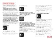
RESTRICTIONS OF USE1. The trailer coupling may only be connected to towingvehicles where the clearances for the <strong>stabiliser</strong> can beobserved, in accordance with EC Directive 94/20 (DIN74058). If these clearances are infringed by specialattachments, then the use must be checked separately.The area above the towball of the vehicle must be freefrom vehicle components or attachments (A) (e.g. sparewheels, platforms etc.)The clearance for the <strong>stabiliser</strong> lever must be at least330mm (B) + the stroke movement (D) (85mm-100mm), which equates to 440mm when used inconjunction with an AL-KO overrun.A B DMIN. 60mmFig 20 Clearances for Stabiliser leverMIN. 67mmFig 1 Necessary ClearancesCMax. 50mm (C) clearance between the centre of thetowball and top of the overrun assembly or fairing, toensure both coupling handle and <strong>stabiliser</strong> lever do notfoul on operation.Maintain the same clearances for othermanufacturers’ overrun assemblies.2. May not be suitable for use with overrun devices which canrevolve above 25° (Fig 2) or BPW overruns fitted with gas struthandbrakes from 2001 model year onwards. (If in any doubtabout usage consult your manufacturer).3. Swan Neck towbars (fixed or detachable) are suitable for use withthe <strong>AKS</strong> <strong>3004</strong> providing they comply to EC Directive 94/20 andhave the required minimum 60mm clearance, measured from thecentre of the towball (Fig 2).4
SAFETY WARNINGS1. In accordance with EC Directive 94/20, couplings of <strong>type</strong>A 50-1 cannot be used (see Fig 3), your warranty will beinvalid if this <strong>type</strong> of towball is used.25°2. For UK use, use the extended neck towball (<strong>type</strong> A50-X).3. A bolted-in <strong>type</strong> ball coupling (Fig 4) is only permissible ifthe thread is locked or welded.Fig 3 A 50-1 Couplings4. The <strong>AKS</strong> <strong>3004</strong> cannot be used with a laterally attachedreversing lever, on the left side, when facing thedirection of traffic.5. The towball must be free from grease, paint and otherresidue, otherwise the stabilising effect is greatly reduced.Coated towballs must have the coating completelyremoved (use 100 or 120 grain emery paper). If this is notdone increased towball wear will occur and may causedamage, or reduce the efficiency of the <strong>stabiliser</strong>.6. If friction pads become contaminated with grease, theyshould be replaced.7. The <strong>AKS</strong> <strong>3004</strong> should only be operated by one person,when opening or closing the handle, to reduce injury risks.Min.60mmFig 2 Max suitable rotation of overrun device is 25°Fig 4 Bolted In Coupling5
FITMENT INSTRUCTIONSStep 5Step 6Step 7Step 9Step 11Step 8 Step 10Step 127
FITMENT NOTES1 Always insert the bolts from the right hand side (whenfacing caravan), to ensure the correct clearances areallowed if fitting AL-KO Security Device (sold separately).2 For non AL-KO overruns, with one horizontal and onevertical fixing bolt, insert the front bolt through thewasher, overrun shaft and internal spacer (where used).Finally, fit hexagonal self-locking nut and torque to120Nm for 10,9 class bolts or 86Nm for 8,8 class bolts.PLEASE NOTE THAT ON MOST OVERRUN ASSEMBLIES, THEDAMPER IS SECURED BY THE REAR RETAINING BOLT ANDTELESCOPES OUT INDEPENDENTLY.NOTE: The <strong>AKS</strong> <strong>3004</strong> is designed for 50mm draw shafts.For smaller diameter shafts, spacers must be used.These are provided with your <strong>stabiliser</strong> kit.Shaft Dia. RequirementsTake Mushroom Headed Coachbolt and insert fromtop, fit original curved washer (from your overrun) andhexagonal self-locking nut and torque to 86Nm (8,8 classbolt supplied).NOTEThe class of bolt will be stamped onto the bolt head.50mm35mm46mmNo spacers required7.5mm spacer2.0mm spacer - non AL-KO8
FITMENT NOTESIt may also be necessary to replace the gaiter accordingto the different diameter draw shafts, see below for details(refers to AL-KO overruns only).Shaft Dia. Gaiter Amendments35mm50mmNo amendments necessary, use existing gaiter.Fit smaller diameter of gaiter flush to end of<strong>stabiliser</strong> and secure larger diameter of gaiterwith the retaining ring included with this kit.Gaiters as per Fig 5/Item A, this is securedimmediately after the coupling and cantherefore be used again.Gaiters as per Fig 5/Item B, cannot be usedagain. Replace with gaiter included with this kit.SPARE PARTS1 Spare parts are safety critical! For this reason when fittingspare parts in our products we recommend the use oforiginal AL-KO parts. The reliability, safety and suitabilityof parts designed especially for our products, has beendetermined using a special test procedure. In spite ofconstantly monitoring the market we are unable to assessor vouch for any other products.2 Repairs should only be carried out by trained and qualifiedworkshop personnel. A list of AL-KO Approved ServiceCentres is available online at www.al-ko.co.uk.3 Always quote the ETI number printed on this product,when enquiring about spare parts.FOR YOUR OWN SAFETY PLEASE CHECK THE FOLLOWING:ABabEnsure in both cases that the damper is correctlyconnected, push the drawshaft in and out - you will feelresistance when the damper is correctly located.Self-locking nuts must only be used once - if removedreplaced with <strong>new</strong> ones.Fig 5 Gaiter Amendments9
OPERATING INSTRUCTIONS<strong>AKS</strong> <strong>3004</strong> SPECIFICATIONSCoupling Handle (Fig 7/Item 1)Stabiliser Lever (Fig 7/Item 2)PREPARATION FOR COUPLING/UNCOUPLINGThe Stabiliser lever (Fig 7/Item 2) must be in theuppermost position (open).COUPLING UPPull the coupling handle (Fig 8/Item 1) up in the directionof arrow. The coupling mechanism has an open position, aslong as the <strong>AKS</strong> <strong>3004</strong> is not placed on the ball, the handlewill remain open. Put the opened coupling onto the cleantowball. The handle must now make an audible click andreturn to the flat position.WARNINGThe coupling is correctly engaged when the green edge ofthe safety indicator button is visible (Fig 9/Item 2).STABILISER UNITTo operate the <strong>stabiliser</strong> (once coupled to the towball), simplypress the <strong>stabiliser</strong> lever down as far as it will go (Fig 9/Item 3).To ensure the <strong>stabiliser</strong> is correctly coupled, check the arrowheadlines up with the black line marked 2 (Fig 9 /Item 4 and Fig 13/C).UNCOUPLINGPull the <strong>stabiliser</strong> lever up as far as it will go, open the couplinghandle and lift the <strong>AKS</strong> <strong>3004</strong> from the towball. With larger noseloads, coupling and uncoupling can be made easier by using thejockey wheel to assist lifting.NOTEThe friction pads (Fig 10/Items 1, 2 & 3) are pressed against thetowball and hence generate a stabilising/damping force. Thesepads are therefore subject to wear over time, however they willhave a long service life (circa.30,000 miles), provided they are wellmaintained and kept free of grease/dirt.10
OPERATING INSTRUCTIONSAL-KO11AL-KOFig 6 <strong>AKS</strong> <strong>3004</strong> StabiliserFig 8 Pull Coupling Handle Up2312432Fig 7 Raise Stabiliser LeverFig 9 Correct Engagement With TowballFig 10 <strong>AKS</strong> <strong>3004</strong> Friction Pads11
OPERATING INSTRUCTIONSMANOEUVRINGFor easier manoeuvring (on campsites etc), pull the <strong>stabiliser</strong>lever to the ‘up’ position.Please do not use the <strong>stabiliser</strong> lever as a manoeuvringhandle. Please use the handles on the caravan or fit the AL-KOmanoeuvring handle to your jockey wheel (available separately).1. During opening or closing, the <strong>AKS</strong> must only beoperated by one person.2. Press <strong>stabiliser</strong> lever down by hand force only. DO NOTuse your foot or an extension bar, this will damage thecomponents (Fig 11).3. When opening or closing the <strong>stabiliser</strong> lever, pleaseensure your hand does not touch the coupling handle -you may accidentally trap your fingers (Fig 11).Fig 11 How NOT to operate the <strong>stabiliser</strong> lever12
OPERATING INSTRUCTIONSNOISES WHILST DRIVINGAs a rule, the friction pads of the <strong>AKS</strong> <strong>3004</strong> do not make a noiseduring driving. Any clicking, creaking or squeaking noises thatdo arise may be due to the following:a. Foreign bodies, dirt or exhaust particle build up between thefriction pad and towball.b. Dry operation of the drawshaft inside the overrun device.c. A detachable towball which has too much play in thelocking mechanism.REMEDIAL ACTIONa. Clean the towball and friction pads before each journey bylightly rubbing the surfaces with a light emery paper (100-120 grit) or use brake cleaning fluid to remove the build up.b. Lubricate the drawshaft sleeve via the grease nipples. Inaddition, push the gaiter forward and grease (DIN 51 825KTA 3K) the exposed part of the shaft (Fig 12).c. Visit a specialist workshop to have the ball holding areachecked for damage and the locking mechanism forfunction. If necessary, change the towball.Fig 12 Remedial Action13
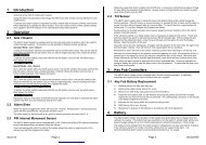
SERVICING AND CLEANINGCHECKING THE EFFICIENCY OFTHE SIDE FRICTION PADS11. Check that the <strong>stabiliser</strong> is correctly coupled by ensuringthe coupling handle is fully down and the red indicatorbutton is in the raised position.2. Push the <strong>stabiliser</strong> lever (Fig 13/Item 1) down untilresistance is felt (i.e. The friction pads are in contact withthe ball but not yet under pressure).3. Check the position of the arrowhead on the arm of the<strong>stabiliser</strong>. If it lines up with the two green lines then thefriction pads are still as <strong>new</strong> (Fig 13/A).4. If the arrowhead lines up with the two red lines then thefriction pads are worn and should be replaced immediately(Fig 13/B).A2B2C2NOTEWhen the <strong>stabiliser</strong> lever is correctly applied, the arrowheadshould line up with the black line marked 2 (Fig 13/C).NOTEThe friction pads do not require any form of lubrication andshould be cleaned with a fine emery paper prior to everyjourney. It is not necessary to adjust the friction pads.1111Fig 13 Checking Left/Right Friction Pads1114
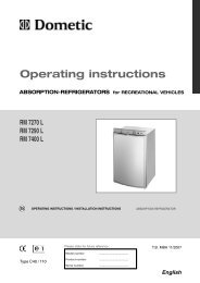
SERVICING AND CLEANINGCHECKING THE EFFICIENCY OF THEFRONT/REAR FRICTION PADS1. Couple the <strong>AKS</strong> <strong>3004</strong> <strong>stabiliser</strong> to the towball but do notactivate the <strong>stabiliser</strong>.2. If a green indicator is visible (on the handle), then the<strong>AKS</strong> <strong>3004</strong> is in a <strong>new</strong> condition or the pads and towballare within the permissible limits (Fig 16/Item 2).3. If only a red indicator is visible (Fig 17/Item 3), then thismay have the following causes:a. <strong>AKS</strong> <strong>3004</strong> is okay but the towball has reached thelowest limit of 49.61mm.b. <strong>AKS</strong> <strong>3004</strong> <strong>stabiliser</strong> shows signs of wear.c. Towball is in a <strong>new</strong> condition (50mm) but the front/rear friction pads show a high degree of wear.Establish the diameter of the towball so thatconclusions may be drawn as to the wear of thefriction pads (ball diameter must not be less than49.61mm).FRICTION PAD REPLACEMENT (FRONT/REAR)1. Uncouple the <strong>AKS</strong> <strong>3004</strong> <strong>stabiliser</strong>.2. Remove the soft dock (pull up & off), (Fig 20/Item 1).3. Press the safety indicator outwards and secure with SW14 hex.spanner (not included), (Fig 20/ Item 2).4. Remove cheese-head screw (Fig 20/Item 3 & Fig 18), usingspecial torx tool.5. Press friction lining recess (Fig 20/Item 4) inwards and pulldown and out.6. Open coupling handle (Fig 20/Item 5).7. Remove countersunk head cap screw using special torx tool(Fig 20/Item 6 & Fig 19).8. Press friction pad inwards with a screwdriver and remove.9. Fit <strong>new</strong> friction pads in reverse. Tighten screws to 5Nm (Fig 20/Items 3&6)10. Replace rubber soft dock, insert top section then bottom.16
SERVICING AND CLEANING2512Fig 33 16 Wear indicator - good conditionFig 18 Cheese-head screw revealed3346Fig 17 Wear indicator - poor conditionFig 19 Remove Head Cap ScrewFig 20 Friction Pad Replacement17
SERVICING AND CLEANINGIMPORTANT MAINTENANCE & CLEANING ADVICE1. The towball should be cleaned regularly to remove greaseor other residue, to maintain the efficiency of the frictionpads. The use of thinners, white spirit or brake cleaner isrecommended for cleaning the towball and friction pads.2. If friction pads are contaminated, they should not becleaned but replaced.3. The surface of the towball must be free of grooves, rustor seizing marks.LUBRICATIONShould lubrication of the <strong>stabiliser</strong> parts become necessary,then the following must be observed.a. Clean all parts thoroughly.b. Areas may only be covered with a thin film of grease (Fig 21).c. Use multipurpose grease DIN 51825 KTA 3K.184. Towballs coated with paint or similar, must have thissurface completely removed (use 100 or 120 grainemery paper). If this is not done, increased towball wearwill occur and may cause damage to the <strong>AKS</strong> <strong>3004</strong><strong>stabiliser</strong> components.5. In winter, you should carefully spray only the visualindicator with de-icer.Fig 21 Lubrication pointsWARNINGWhen lubricating,ensure none gets intothe friction pad ortowball holding area.
FAQSSTABILISERCAN THE RED AND/OR GREEN INDICATORBUTTONS BE REPLACED IF BROKEN/MISSING?This is usually caused by catching the button with the hitchlock when fitting the hitch lock. The green section can insome circumstances be replaced. Please contact AL-KO forfurther advice.The red part cannot be replaced.THE STABILISER ARMS KEEP LIFTINGUP WHEN I TRAVEL.The most likely cause is the handbrake handle catching onthe <strong>stabiliser</strong> lever when braking.Gently tease the handle away from the contact point - 5mmshould be sufficient. Whilst doing this, make sure yousupport the base of the handbrake with a block of wood tostop it coming off the ratchet plate.FRICTION PADSWHEN SHOULD I CHANGE MY FRICTION PADS?The friction pad life expectancy is around 30,000 miles and can beprolonged by regular cleaning with fine grade emery paper. Simplyremove them according to the instructions on pages 15-17, cleanthem and replace.However, they will wear out and this can be monitored via wearindicators on your <strong>stabiliser</strong>. See pages 14-17 for wear indicatorinformation, and instructions on changing them.MY FRICTION PADS LOOK ‘GLASSY’WITH BITS FLAKING OFF.Contamination has built up on the pads. This could be due togrease on the towball, spray from the road, diesel fumes or failureto remove all of the coating on the towball.You need to remove the friction pads according to the instructionson pages 15-17, and rub them lightly with a fine grade emerypaper. AL-KO recommend cleaning the pads in this way after everyjourney to prevent build up and prolong friction pad life.19
FAQSWHEN TOWING I CAN HEARLOUD CREAKING OR GROANING.2 possible causes:1 The incorrect towball could be fitted. Check your towballis compatible with your <strong>stabiliser</strong>, and if it isn’t replaceit immediately. Failure to do so could result in yourcaravan becoming unhitched during towing.The necessary clearances are outlined on page 4, andAL-KO recommends the AL-KO extended neck towballwhich complies to all the necessary specifications.2 Contamination may have built up on the friction pads.This could be due to grease on the towball, spray fromthe road, diesel fumes or failure to remove all of thecoating on the towball.You need to remove the friction pads according to theinstructions on pages 15-17 and rub them lightly with a finegrade emery paper.AL-KO recommend cleaning the pads in this way after everyjourney to prevent build up and prolong friction pad life.THE END HAS SNAPPED OFF OF MY FRICTION PAD.This usually happens when the pads have not been fullydisengaged before dropping the <strong>stabiliser</strong> onto the towball. Youwill need to replace the friction pad with a <strong>new</strong> one. To avoid thisin future always place, rather than drop, the <strong>stabiliser</strong> onto thetowball and ensure the <strong>stabiliser</strong> lever has been lifted fully.CAN I TOW MY CARAVAN WITHOUT ACTIVATING THEFRICTION PADS?Yes, but AL-KO do not recommend it. It is the hitch handle thatattaches the <strong>stabiliser</strong> to the towball. If you do not activate yourfriction pads then you will have no damping benefits.TOWBALLMY TOWBALL HAS GREASE ON IT. CAN I USE IT WITHAN <strong>AKS</strong> STABILISER?Under no circumstances can a greased towball be used with an<strong>AKS</strong> <strong>stabiliser</strong>. Ensure you remove all grease before hitching up.Use a cloth to remove the excess grease, and use brake cleaner toremove any residue. We do not recommend methylated spirit asthis can leave a greasy residue.20
COMPLEMENTARY PRODUCTSAL-KO SECURITY DEVICEAL-KO Security Devices provide a substantial deterrentagainst the theft of the caravan or trailer. They lock over thecoupling handle, preventing unauthorised uncoupling.Fitting the supplied Safety Ball into the coupling head whenthe Security Device is applied, prevents the caravan or trailerfrom being coupled to another vehicle.The Security Device is manufactured from high density steeland is TUV approved.Visit www.al-ko.co.ukfor more information.FRICTION PADSMade from low-wear material, four specially engineered frictionpads surround the towball and continue to ensure optimumfriction damping.EXTENDED NECK TOWBALLDesigned especially for use with the AL-KO<strong>AKS</strong> <strong>stabiliser</strong>s the Extended Neck Towball hasan extended machined neck to allow correct<strong>stabiliser</strong> articulation and clearances.HITCH COVERDesigned to fit the <strong>AKS</strong> <strong>3004</strong>Stabilisers, the hitch cover willhelp protect your <strong>stabiliser</strong> fromthe elements.The water/fade resistant padded foam fabric has a velcro fasteningand eyelet for padlock security (padlock not included).Visit www.al-ko.co.uk for more information.22
COMPLEMENTARY PRODUCTSAL-KO ATC TRAILER CONTROLATC Trailer Control is an electronic braking device for caravansand works in a similar way to ESP on some tow cars. ATCmonitors for instability and takes the necessary action toprevent the caravan from snaking by gently applying thecaravan brakes, extending the distance between the tow carand caravan and bringing the caravan back into line. ATC hasbeen fitted as standard on a wide range of caravans since itslaunch in 2007 and is also available for retrofit.For more information on how ATC works, please visit ourwebsite at www.al-ko.co.uk.THE AL-KO FORMULA FOR OPTIMUM SAFETYThe AL-KO Formula for Optimum Safety is a combination ofindustry leading technology that ensures the safest possible drivingconditions for caravan owners. When used in conjunction withAL-KO <strong>AKS</strong>, there is no safer package for towing a caravan.The AL-KO <strong>AKS</strong> Stabiliser device permanently suppresses smallswinging and pitching movements in the trailer and increases thecritical driving speed by approx 20%.As an emergency system, AL-KO ATC automatically safeguardsagainst a number of critical driving conditions.A safe driving style and correct loading combine with AL-KO’sadvanced technology to ensure optimum safety and unparalleledtowing stability.23