Performance Evaluation of Time Hopping UWB ... - Ripublication.com
Performance Evaluation of Time Hopping UWB ... - Ripublication.com
Performance Evaluation of Time Hopping UWB ... - Ripublication.com
Create successful ePaper yourself
Turn your PDF publications into a flip-book with our unique Google optimized e-Paper software.
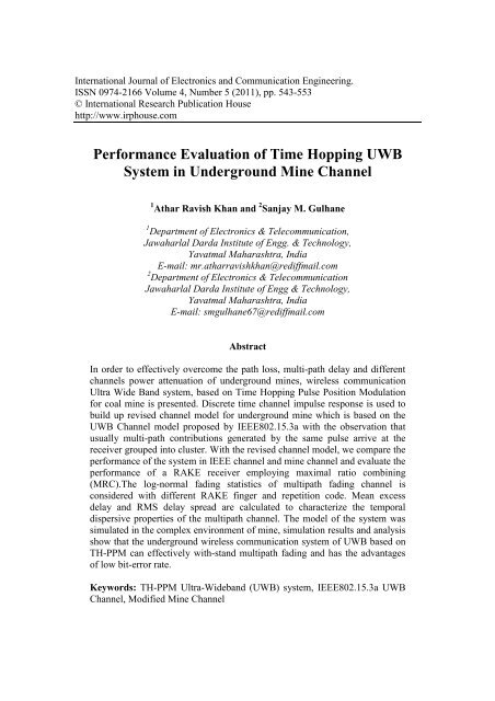
International Journal <strong>of</strong> Electronics and Communication Engineering.ISSN 0974-2166 Volume 4, Number 5 (2011), pp. 543-553© International Research Publication Househttp://www.irphouse.<strong>com</strong><strong>Performance</strong> <strong>Evaluation</strong> <strong>of</strong> <strong>Time</strong> <strong>Hopping</strong> <strong>UWB</strong>System in Underground Mine Channel1 Athar Ravish Khan and 2 Sanjay M. Gulhane1 Department <strong>of</strong> Electronics & Tele<strong>com</strong>munication,Jawaharlal Darda Institute <strong>of</strong> Engg. & Technology,Yavatmal Maharashtra, IndiaE-mail: mr.atharravishkhan@rediffmail.<strong>com</strong>2 Department <strong>of</strong> Electronics & Tele<strong>com</strong>municationJawaharlal Darda Institute <strong>of</strong> Engg & Technology,Yavatmal Maharashtra, IndiaE-mail: smgulhane67@rediffmail.<strong>com</strong>AbstractIn order to effectively over<strong>com</strong>e the path loss, multi-path delay and differentchannels power attenuation <strong>of</strong> underground mines, wireless <strong>com</strong>municationUltra Wide Band system, based on <strong>Time</strong> <strong>Hopping</strong> Pulse Position Modulationfor coal mine is presented. Discrete time channel impulse response is used tobuild up revised channel model for underground mine which is based on the<strong>UWB</strong> Channel model proposed by IEEE802.15.3a with the observation thatusually multi-path contributions generated by the same pulse arrive at thereceiver grouped into cluster. With the revised channel model, we <strong>com</strong>pare theperformance <strong>of</strong> the system in IEEE channel and mine channel and evaluate theperformance <strong>of</strong> a RAKE receiver employing maximal ratio <strong>com</strong>bining(MRC).The log-normal fading statistics <strong>of</strong> multipath fading channel isconsidered with different RAKE finger and repetition code. Mean excessdelay and RMS delay spread are calculated to characterize the temporaldispersive properties <strong>of</strong> the multipath channel. The model <strong>of</strong> the system wassimulated in the <strong>com</strong>plex environment <strong>of</strong> mine, simulation results and analysisshow that the underground wireless <strong>com</strong>munication system <strong>of</strong> <strong>UWB</strong> based onTH-PPM can effectively with-stand multipath fading and has the advantages<strong>of</strong> low bit-error rate.Keywords: TH-PPM Ultra-Wideband (<strong>UWB</strong>) system, IEEE802.15.3a <strong>UWB</strong>Channel, Modified Mine Channel
544 Athar Ravish Khan and Sanjay M. GulhaneIntroductionThe <strong>com</strong>plex natural environment and operating conditions in coal mine restrict thedevelopment <strong>of</strong> mine wireless <strong>com</strong>munication seriously. Ultra-Wide band (<strong>UWB</strong>)Wireless Communication with a high transfer rate, low power consumption, antiinterferenceis conducive to resolve the issue <strong>of</strong> radio <strong>com</strong>munication under the<strong>com</strong>plex environment in underground mines. Ultra-Wideband (<strong>UWB</strong>) technology hasgained much interest for its applications in wireless <strong>com</strong>munications. The necessityfor wireless <strong>com</strong>munications in underground mines is well understood. Some<strong>com</strong>panies have started to deploy modern wireless networks in mine galleries with theobjective <strong>of</strong> increasing safety and productivity. Ultra wide band (<strong>UWB</strong>) wireless<strong>com</strong>munication system has became the principal scheme <strong>of</strong> short distance high speeddigital transmission, resisting on multipath interference as well as its low powerconsumption. The analysis and design <strong>of</strong> a <strong>UWB</strong> <strong>com</strong>munication system requires, anaccurate channel model to determine the maximum achievable data rate, efficientmodulation schemes, and associated signal processing algorithms [1]. This paperevaluate a performance <strong>of</strong> an Ultra-Wideband (<strong>UWB</strong>) system in an underground minechannel. The remainder <strong>of</strong> the paper is organized as follows. In the next section wepresent modulate technique and Choice <strong>of</strong> <strong>UWB</strong> wave in coal mine. Section 3 dealswith channel modeling and receiver structure in Underground Mine and in Section. 4the paper ends with simulation results and conclusion.Choice <strong>of</strong> <strong>UWB</strong> Wave and Modulate Technique in UndergroundMineChoice <strong>of</strong> Modulate Technique and channel coderIn TH-<strong>UWB</strong> <strong>com</strong>bine with binary PPM (2PPM-TH-<strong>UWB</strong>), the <strong>UWB</strong> signal can beschematized to be generated as shown in Figure(1).Given the binary sequence to betransmitted b= (..,b 0 ,b 1 ,…b k ,b k+1 ,…),generate at rate <strong>of</strong> R b =1/T b bits/sec, a firstsystem repeats each bit N s times and generates a binarysequence(.,b 0 ,b 0 ,…b 0 ,b 1 ,b 1 ,..,b k+1 ,b k+1 …b k+1 ,.)=(..a 0 ,a 1 …..a j ,a j+1 ) = a at the rate <strong>of</strong>R cb =N s /T b =1/T s bits/s. This system introduce the redundancy and is a(N s ,1) blockcoder indicated as a code repetition coder in classical terminology this is channelcoder. A second block called a transmission coder applies an integer-valued codec=(..c 0 ,c 1, …c j ,c j+1 ,…) to the binary sequence a=(..a 0 , a1…..a j , aj +1 ) and generate a newsequence d. The generic element <strong>of</strong> the sequence d is express asd j =c j T c +a j ε (1)where T c and ε are constant terms that satisfy the condition c j T c + ε < T s for all c j Onealso has, in general, ε< T c , d is a real-valued sequence as opposed to a, which isbinary and to c, which is integer-valued, assume that c is a pseudorandom code, itsgeneric element c j being an integer verifying 0 ≤ c j ≤ N h - 1. The code c might beperiodic, and in that case, its period is indicated by N p . Two particular cases are worthdiscussing. The first corresponds to the absence <strong>of</strong> periodicity in the code, that is, N ptends to ∞ and the second to N p = N s . In the second case, which is the most <strong>com</strong>monly
<strong>Performance</strong> <strong>Evaluation</strong> <strong>of</strong> <strong>Time</strong> <strong>Hopping</strong> <strong>UWB</strong> System 545adopted, the periodicity <strong>of</strong> the code coincides with the length <strong>of</strong> the repetition code[7]. The coded real-valued sequence d enters a third system, the PPM modulator,which generates a sequence <strong>of</strong> unit pulses (Dirac pulses δ(t) ) at a rate <strong>of</strong> R p = N s /T b =1/T s pulses/s. These pulses are located at times jT s +d j , and are therefore shifted intime from nominal positions jT s by d j . Pulses occur at times (jT s +c j T c +a j ε). Note thatcode c introduces a TH shift on the generated signal, and it is for this reason that it isindicated as TH code. Note that the shift introduced by the PPM modulator, a j ε, isusually much smaller than the shift introduced by the TH code, c j T c , that is, a j ε < c j T c ,except for c j = 0. T c is called chip time refer figure(2). The last system is the pulseshaper filter with impulse response p(t). The impulse response p(t) must be such thatthe signal at the output <strong>of</strong> the pulse shaper filter is a sequence <strong>of</strong> strictly nonoverlappingpulses. The most <strong>com</strong>monly adopted pulse shapes is second derivative <strong>of</strong>a Gaussian function.Figure 1: Proposed 2PPM-TH-<strong>UWB</strong> System model for Underground Mine0.080.06Ts= Frame timeTc =Chip <strong>Time</strong>Example: THcode = [ 2 0 1 1 2 ]numbits = 2 number <strong>of</strong> bits generated by the source [1 0]Ns = 3; number <strong>of</strong> pulses per bitNp = 5; periodicity <strong>of</strong> the TH codeAmplitude [V]0.040.02Bit=1Tm =Pulse DurationBit=00-0.02TH1=2TH1=2TH2=0TH3=1 TH4=1 TH5=20 0.2 0.4 0.6 0.8 1 1.2 1.4 1.6 1.8<strong>Time</strong> [s]x 10 -8Figure 2: 2PPM-TH with Pulse Shape.
546 Athar Ravish Khan and Sanjay M. GulhaneNarrow impulse waveNarrow impulse wave has great infection in <strong>UWB</strong> <strong>com</strong>munication system, so it isvery important to choose the narrow impulse. The narrow impulse signal waves in<strong>com</strong>mon used now include the Guass wave, Cosine wave, multi-period impulse waveand so on. The Gauss wave applied most <strong>com</strong>monly <strong>of</strong> these [1]. In the non-carrierwave impulse <strong>UWB</strong> <strong>com</strong>munications, we usually modeling the transmitting andreceiving antenna to a differential operation. The Gauss impulse signal can beexpressed aspt 1e √2πσ √2αe Where α 2 =4πσ 2 is shape factor and σ 2 is variance ,to be radiate in efficient wayGaussian derivatives are suitable [7] the most currently adopted pulse shape ismodeled as the second derivative <strong>of</strong> a Gaussian function described byd ptdt 14π te α 3Ideally, a second derivative Gaussian pulse can be obtained at transmittingantenna if the antenna is fed with a current pulse shaped as the first derivative <strong>of</strong>Gaussian waveform ,the radiating pulse being proportional to the derivative <strong>of</strong> thedrive current in an ideal antenna(Immoreev and Sinyavin 2002) [7]. The signal s(t) atthe output <strong>of</strong> the cascade <strong>of</strong> the systems shown in Figure(1) can be expressed asfollows:st ptjT c T a εNote that the bit interval, or bit duration, that is, the time used to transmit one bitT b is: T b = N s T s . Also note that in Eq. (4), the term c j T c defines pulse randomization ordithering with respect to the nominal instances <strong>of</strong> time occurring at multiples <strong>of</strong> T s . Ifwe represent the time shift introduced by the TH code c j T c by a random TH dither η j ,which can be assumed to be distributed between 0 and T η < Ts, we obtain:st ptjT η a εAs noticed above, η j is usually much larger than ε. The global effect <strong>of</strong> these twoterms is to introduce a random time shift, distributed between 0 and T η + ε < Ts, whichwill be indicated by θ j leading to the following expression for the transmitted signalst ptjT θ 2456
<strong>Performance</strong> <strong>Evaluation</strong> <strong>of</strong> <strong>Time</strong> <strong>Hopping</strong> <strong>UWB</strong> System 547Receiver Structure and Channel Modeling in Underground MineChannel ModelingIn July 2003, the Channel-Modeling sub-<strong>com</strong>mettee <strong>of</strong> study group IEEE 802.15.SGapublished the final report regarding the <strong>UWB</strong> indoor multi-path channel model (IEEE802.15.SG3a,2003).This model should be used for evaluating the performance <strong>of</strong>different physical layers as submitted to the IEEE 802.15.3 task group. IEEE channel-Modeling sub-<strong>com</strong>mettee finally converged an a model based on the cluster approchproposed by Turin and others in 1972(Turin et.al.1972)and further formalized bySaleh and Valenzuela in 1987(Saleh and Valenzuela,1987)[7]in the seminal work onstatistical modeling for indoor multi-path propagation .The S-V model is based on theobservation that usually multi-path contributions generated by the same pulse arrive atthe receiver grouped into cluster. In this model the gain <strong>of</strong> the n th ray <strong>of</strong> k th cluster is a<strong>com</strong>plex random variable.To better fit the data resulting from <strong>UWB</strong> measurement campaign, the IEEEgroup proposed a few modifications to S-V model. In particular, a log-normaldistribution was suggested for characterizing the multi-path gain amplitude, and anadditional log-normal variable was introduced for representing the fluctuations <strong>of</strong> thetotal multipath gain. Finally, the channel coefficient was assumed to be real variablesrather than <strong>com</strong>plex variables. The channel impulse response <strong>of</strong> the IEEE model canbe express as Where X is a lognormal distributed random variable representing the magnitude<strong>of</strong> channel gain. N is the observed number <strong>of</strong> clusters. K(n) is the received number <strong>of</strong>multipath in the n th cluster. α nk is coefficients <strong>of</strong> the k th path in the n th cluster. T n is thearrival time <strong>of</strong> the nth cluster. τ nk is the k th path delay in the n th cluster. Table 1 showsthe parameter required for the setting <strong>of</strong> IEEE <strong>UWB</strong> Channel and Table 2 ShowsParameter for environmental characteristics <strong>of</strong> Underground Mine [6].7Table 1: Parameter required for the setting <strong>of</strong> IEEE <strong>UWB</strong> Channel.IEEE <strong>UWB</strong> ChannelΛ λ Г γ(1/ns) (1/ns)0.0233 2.5 7.1 4.3σ ξ (dB) σ ζ (dB) σ g (dB) Type3.3941 3.3941 3 LOSWhere Λ is the cluster average arrival rate, λ in pulse average arrival rate ,Г ispower delay factor for cluster, γ is power delay factor for pulse within a cluster, σ ξ isstandard deviation <strong>of</strong> the fluctuation <strong>of</strong> the channel coefficient for the clusters, σ ζ is
548 Athar Ravish Khan and Sanjay M. Gulhanestandard deviation <strong>of</strong> the fluctuation <strong>of</strong> the channel coefficient for pulse within a theclusters, σ g , is standard deviation <strong>of</strong> the channel amplitude gain.Table 2 Parameter for environmental characteristics <strong>of</strong> Underground MineModified <strong>UWB</strong> Channel forUnderground MineΛ λ Г γ(1/ns) (1/ns)0.0667 2.1 36 24σ ξ (dB) σ ζ (dB) σ g (dB) Type3.3941 3.3941 3 LOSThe mean excess delay and RMS delay spread are two important parameters useto characterize the temporal dispersive properties <strong>of</strong> the multipath channel. The RMSdelay spread parameter determines the frequency selectively <strong>of</strong> the channel whichdegrades the performance <strong>of</strong> digital <strong>com</strong>munication systems. The RMS delay spreadlimits the maximum data transmission rate that can be reliably supported by thechannel figure (5) shows the RMS delay <strong>of</strong> Underground Mine Channel and figure (6)shows the Excess delay <strong>of</strong> Underground Mine Channel, simulated for 100 number <strong>of</strong>channel. The clustering <strong>of</strong> the multipath arrivals is evidence observed in figure (3),this validates the multi-paths arriving in clusters <strong>of</strong> <strong>UWB</strong> channel measurement data.It is the typical result in the multipath attenuation channel, any more the amplitudefading statistics <strong>of</strong> the channel impulse response are exponential. It can be seen thatbefore 300ns the amplitude fading lentamente, here the model is able to best fit thechannel propagation law, but after 300ns, the amplitude fading prick up and almostnear zero.Discrete <strong>Time</strong> Mine Channel Impulse Response10.80.60.4Amplitude G ain0.20-0.2-0.4-0.6-0.8-10 100 200 300 400<strong>Time</strong> [ns]Figure 3 Discrete time impulse response <strong>of</strong> Underground Mine Channel.
<strong>Performance</strong> <strong>Evaluation</strong> <strong>of</strong> <strong>Time</strong> <strong>Hopping</strong> <strong>UWB</strong> System 549IEEE <strong>UWB</strong> Channel Impulse Response10.80.60.4Amplitude Gain0.20-0.2-0.4-0.6-0.8-10 100 200 300 400<strong>Time</strong> [ns]Figure 4 Discrete time impulse response <strong>of</strong> IEEE <strong>UWB</strong> channel55RMS delay (nS)5045403530250 10 20 30 40 50 60 70 80 90 100Channel numberFigure 5 Root Mean Square delay <strong>of</strong> Underground Mine Channel.70Excess delay (nS)6560555045403530250 10 20 30 40 50 60 70 80 90 100Channel numberFigure 6 Excess delay <strong>of</strong> Underground Mine Channel.
<strong>Performance</strong> <strong>Evaluation</strong> <strong>of</strong> <strong>Time</strong> <strong>Hopping</strong> <strong>UWB</strong> System 551rt a s t τ nt9where n(t) is AWGN at the receiver input. Equation (8) can be rewritten for IRtransmission on the basis <strong>of</strong> statistical channel model discussed equation(7)rt X E a a p t jT φ τ nt10Where E TX Transmitted energy per pulse ,a j amplitude <strong>of</strong> j th transmitted pulse T s isaverage pulse repetition time, φ j is time dithering .Simulation ResultsFigure 8 is the curve <strong>of</strong> bit error rate (BER) with signal noise ratio (SNR) <strong>of</strong> the abovesystem for IEEE <strong>UWB</strong> Channel and Modified Underground Mine channelenvironment.10 0 E b/N 0IEEE ChannelMine Channel10 -1P r e10 -210 -310 -40 2 4 6 8 10 12 14 16 18 20Figure 8 BER performance in IEEE channel Vs Underground Mine ChannelFigure 9 and figure 10 is the curve <strong>of</strong> bit error rate (BER) with signal noise ratio(SNR) which evaluate the performance <strong>of</strong> RAKE receiver for different RAKE fingerand different value <strong>of</strong> repeat bits in the transmission coder respectively for modifiedUnderground Mine channel environment.
552 Athar Ravish Khan and Sanjay M. Gulhaneyg10 0 E b/N 0Srake(10-Branches)Srake(8-Branches)Srake(5-Branches)Srake(3-Branches)10 -1Pr e10 -210 -310 -40 2 4 6 8 10 12 14 16 18 20Figure 9: BER performance in Underground Mine Channel for different RAKEfinger10 0 10 -1E b/N 0Ns=50Ns=40Ns=30Ns=20P r e10 -210 -310 -40 2 4 6 8 10 12 14 16 18 20Figure 10: BER performance in Underground Mine Channel for different repetitioncoderConclusionIn this paper, the propagation <strong>of</strong> the <strong>UWB</strong> signal in Underground Mine is analyzed.The performance <strong>of</strong> a RAKE receiver for 2PPM-TH- <strong>UWB</strong> system was analyzed inUnderground Mine channel model and IEEE <strong>UWB</strong> channel based on an extensive set<strong>of</strong> indoor channel measurements. Simulation results and analysis show that theunderground wireless <strong>com</strong>munication system <strong>of</strong> <strong>UWB</strong> based on TH-PPM can
<strong>Performance</strong> <strong>Evaluation</strong> <strong>of</strong> <strong>Time</strong> <strong>Hopping</strong> <strong>UWB</strong> System 553effectively with-stand multipath fading and has the advantages <strong>of</strong> low bit-error rate.Research is continuing into developing effective RAKE architectures to <strong>com</strong>binelarge numbers <strong>of</strong> multipath <strong>com</strong>ponents with low <strong>com</strong>plexity.AcknowledgmentThe authors would like to thank firstly, our GOD, and all friends who gave us anyhelp related to this work. Finally, the most thank is to our families and to our countryINDIA which born us.References[1] SUN Yanjing, PENG Li, LIU Xue “Wireless Channel Model <strong>of</strong> <strong>UWB</strong> forUnderground Tunnels in Coal Mine” IEEE 2009 978-1-4244-3693[2] A Saleh, R Valenzuela., “A Statistical Model for Indoor MultipathPropagation,” IEEE JSAC, 1987, vol.5, pp. 128-137.[3] Mathieu Boutin, Ahmed Benzakour, Charles L. Despins, “Radio WaveCharacterization and Modeling in Underground Mine Tunnels” IEEETransactions On Antennas And Propagation, pp-540-549 VOL. 56, NO. 2,February 2008[4] Rajeswaran A, Somayazulu V S, Foerster J R, “Rake performance for a pulsebased <strong>UWB</strong> system in a realistic <strong>UWB</strong> indoor channel,”ICC’03[C]. 2003,pp.2879-2883.[5] Abdellah Chehri, Paul Fortier, Pierre-Martin Tardif, “An Investigation <strong>of</strong><strong>UWB</strong>-Based Wireless Networks in Industrial Automation” IJCSNSInternational Journal <strong>of</strong> Computer Science and Network Security, VOL.8 No.2,February 2008[6] Yanjing Sun, Beibei Zhang “System Model <strong>of</strong> Underground <strong>UWB</strong> Based onMB-OFDM” Int. J. Communications, Network and System Sciences, 2011, 4,59-64[7] M.-G. Di Benedetto, G. Gianloca,“Understanding ultra wideband radi<strong>of</strong>undamentals”, Pearson Education LPE 2008 ISBN 978-81-317-2279-4[8] Wei Li, T. Aaron Gulliver and Hao Zhang, “<strong>Performance</strong> <strong>of</strong> Ultra-WidebandTransmission with Pulse Position Amplitude Modulation and RAKEReception” IEEE- ©2005 0-7803-9068[9] Ph. Mariage, M. Lienard, and P. Degauque, “Theoretic a1 and ExperimentalApproach <strong>of</strong> the Propagation <strong>of</strong> High Frequency Waves in Road Tunnels”IEEE Transactions On Antennas And Propagation, Vol. 42, No. 1 , January1994[10] A. Nezampour, M. Nasiri-Kenari and M.G. Shayesteh “Internally coded TH–<strong>UWB</strong>–CDMA system and its performance evaluation” IET Commun., 2007, 1,(2), pp. 225–232


