Manual PDF - Innova Pro
Manual PDF - Innova Pro
Manual PDF - Innova Pro
- No tags were found...

Create successful ePaper yourself
Turn your PDF publications into a flip-book with our unique Google optimized e-Paper software.
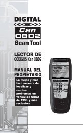
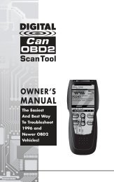
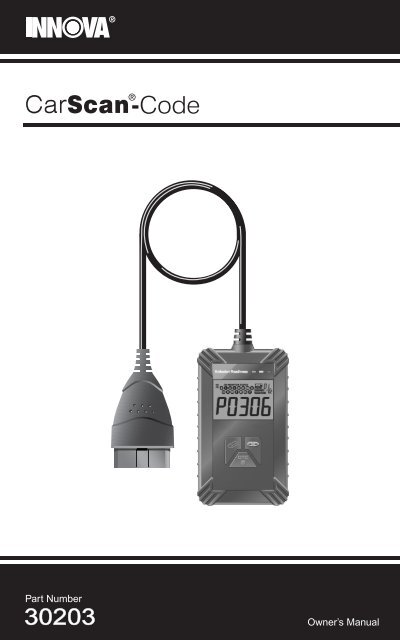
Part Number30203Owner’s <strong>Manual</strong>
Table of ContentsYOU CAN DO IT! .............................................................................. 1SAFETY PRECAUTIONSSAFETY FIRST! ....................................................................... 2ABOUT THE CARSCANVEHICLES COVERED ............................................................. 3CONTROLS AND INDICATORS ............................................. 4DISPLAY FUNCTIONS ............................................................ 5ONBOARD DIAGNOSTICSCOMPUTER ENGINE CONTROLS ......................................... 7DIAGNOSTIC TROUBLE CODES (DTCs) .............................. 12OBD2 MONITORS ................................................................... 15PREPARATION FOR TESTINGBEFORE YOU BEGIN .............................................................. 24VEHICLE SERVICE MANUALS ............................................... 24USING THE CARSCANCODE RETRIEVAL PROCEDURE .......................................... 26ERASING DIAGNOSTIC TROUBLE CODES (DTCs) ............. 28WARRANTY AND SERVICINGLIMITED ONE YEAR WARRANTY........................................... 33SERVICE PROCEDURES ....................................................... 33iOBD2
You Can Do It!EASY TO USE - EASY TO VIEW - EASY TO DEFINEEasy To Use . . . .• Connect the CarScan to the vehicle’stest connector.• Turn the ignition key "On.” DO NOT startthe engine.• The CarScan will automatically link tothe vehicle’s computer.Easy To View . . . .• The CarScan retrieves stored codes anddisplays I/M Readiness status.• Codes are displayed on the CarScan’sLCD display screen; I/M Readiness statusis displayed by LED indicators.Easy To Define . . . .• Visit www.pro.innova.com or the manufacturer'swebsite for Fault CodeDefinitions.OBD2 1
Safety PrecautionsSAFETY FIRSTSAFETY FIRST!This manual describes common test procedures used by experiencedservice technicians. Many test procedures require precautions to avoidaccidents that can result in personal injury, and/or damage to yourvehicle or test equipment. Always read your vehicle's service manualand follow its safety precautions before and during any test or serviceprocedure. ALWAYS observe the following general safety precautions:When an engine is running, it produces carbon monoxide, atoxic and poisonous gas. To prevent serious injury or deathfrom carbon monoxide poisoning, operate the vehicle ONLYin a well-ventilated area.To protect your eyes from propelled objects as well as hotor caustic liquids, always wear approved safety eyeprotection.When an engine is running, many parts (such as the coolantfan, pulleys, fan belt etc.) turn at high speed. To avoid seriousinjury, always be aware of moving parts. Keep a safe distancefrom these parts as well as other potentially moving objects.Engine parts become very hot when the engine is running.To prevent severe burns, avoid contact with hot engineparts.PRNDLBefore starting an engine for testing or trouble-shooting, makesure the parking brake is engaged. Put the transmission inpark (for automatic transmission) or neutral (for manualtransmission). Block the drive wheels with suitable blocks.Connecting or disconnecting test equipment when theignition is ON can damage test equipment and the vehicle'selectronic components. Turn the ignition OFF beforeconnecting the CarScan to or disconnecting the CarScanfrom the vehicle’s Data Link Connector (DLC).To prevent damage to the on-board computer when takingvehicle electrical measurements, always use a digitalmultimeter with at least 10 MegOhms of impedance.The vehicle's battery produces highly flammable hydrogengas. To prevent an explosion, keep all sparks, heated itemsand open flames away from the battery.Don't wear loose clothing or jewelry when working on anengine. Loose clothing can become caught in the fan,pulleys, belts, etc. Jewelry is highly conductive, and cancause a severe burn if it makes contact between a powersource and ground.2 OBD2
About the CarScanVEHICLES COVEREDVEHICLES COVEREDThe CarScan is designed to work on all OBD 2 compliant vehicles. All1996 and newer vehicles (cars and light trucks) sold in the United Statesare OBD 2 compliant. This includes all Domestic, Asian and Europeanvehicles.Some 1994 and 1995 vehicles are OBD 2 compliant. To find out if a1994 or 1995 vehicle is OBD 2 compliant, check the following:1. The Vehicle Emissions Control Information (VECI) Label. This labelis located under the hood or by the radiator of most vehicles. If thevehicle is OBD 2 compliant, the label will state “OBD II Certified.”VEHICLE EMISSION CONTROL INFORMATIONVEHICLEMANUFACTURERENGINE FAMILY EFN2.6YBT2BADISPLACEMENT 2.6LOBD IICERTIFIEDTHIS VEHICLE CONFORMS TO U.S. EPA AND STATEOF CALIFORNIA REGULATIONS APPLICABLE TO1999 MODEL YEAR NEW TLEV PASSENGER CARS.REFER TO SERVICE MANUAL FOR ADDITIONAL INFORMATIONTUNE-UP CONDITIONS: NORMAL OPERATING ENGINE TEMPERATURE,ACCESSORIES OFF, COOLING FAN OFF, TRANSMISSION IN NEUTRALEXHAUST EMISSIONS STANDARDS STANDARD CATEGORYCERTIFICATIONIN-USETLEVTLEV INTERMEDIATEOBD IICERTIFIEDSPARK PLUGTYPE NGK BPRE-11GAP: 1.1MMCATALYST2. Government Regulations require that allOBD2 compliant vehicles must have a“common” sixteen-pin Data LinkConnector (DLC).1 2 3 4 5 6 7 89 10111213141516Some 1994 and 1995 vehicles have 16-pin connectors but are notOBD2 compliant. Only those vehicles with a Vehicle EmissionsControl Label stating “OBD II Certified” are OBD2 compliant.Data Link Connector (DLC) LocationThe 16-pin DLC is usuallylocated under the instrumentpanel (dash), within 12 inches(300 mm) of center of the panel,on the driver’s side of mostvehicles. It should be easilyaccessible and visible from akneeling position outside thevehicle with the door open.LEFT CORNEROF DASHNEARCENTEROF DASHBEHINDASHTRAYOn some Asian and European vehicles the DLC is locatedbehind the “ashtray” (the ashtray must be removed to access it)or on the far left corner of the dash. If the DLC cannot belocated, consult the vehicle’s service manual for the location.OBD2 3
About the CarScanSAFETY FIRSTCONTROLS AND INDICATORS45671328Figure 1. Controls and IndicatorsSee Figure 1 for the locations of items 1 through 9, below.1. ERASE button - Erases Diagnostic Trouble Codes (DTCs)and "Freeze Frame" data from your vehicle's computer, and resetsMonitor status.2. SCROLL button - Scrolls the LCD display to view DTCswhen more than one DTC is present.3. LINK button - Links the CarScan with the vehicle's PCM toretrieve DTCs from the computer's memory, and to view I/MReadiness Monitor status.4. GREEN LED - Indicates that all engine systems are runningnormally (all Monitors on the vehicle are active and performing theirdiagnostic testing, and no DTCs are present).4 OBD2
About the CarScanDISPLAY FUNCTIONS5. YELLOW LED - Indicates there is a possible problem. A “Pending”DTC is present and/or some of the vehicle's emission monitors havenot run their diagnostic testing.6. RED LED - Indicates there is a problem in one or more of thevehicle's systems. The red LED is also used to show that DTC(s)are present. DTCs are shown on the CarScan’s LCD display. In thiscase, the Multifunction Indicator (“Check Engine”) lamp on thevehicle's instrument panel will light steady on.7. LCD Display - Displays test results, CarScan functions and Monitorstatus information. See DISPLAY FUNCTIONS, below, for details.8. CABLE - Connects the CarScan to the vehicle's Data LinkConnector (DLC).DISPLAY FUNCTIONS10 5 4 6128973Figure 2. Display FunctionsSee Figure 2 for the locations of items 1 through 13, below.1. Vehicle icon - Indicates whether or not the CarScan is beingproperly powered through the vehicle's Data Link Connector (DLC).A visible icon indicates that the CarScan is being powered throughthe vehicle's DLC connector.2. Link icon - Indicates whether or not the CarScan iscommunicating (linked) with the vehicle's on-board computer. Whenvisible, the CarScan is communicating with the computer. If the Linkicon is not visible, the CarScan is not communicating with thecomputer.3. DTC Display Area - Displays the Diagnostic Trouble Code (DTC)number. Each fault is assigned a code number that is specific to thatfault.4. MIL icon - Indicates the status of the Malfunction Indicator Lamp(MIL). The MIL icon is visible only when a DTC has commanded theMIL on the vehicle's dashboard to light.5. Pending icon - Indicates the currently displayed DTC is a "Pending"code.OBD2 5
About the CarScanDISPLAY FUNCTIONS6. PERMANENT icon - Indicates the currently displayed DTC is a“Permanent” code.7. FREEZE FRAME icon - Indicates that “Freeze Frame” data has beenstored in the vehicle’s computer for the currently displayed DTC.8. Code Number Sequence - The CarScan assigns a sequencenumber to each DTC that is present in the computer's memory,starting with "01.” This helps keep track of the number of DTCspresent in the computer's memory. Code number "01" is always thehighest priority code, and the one for which "Freeze Frame" datahas been stored.9. Code Enumerator - Indicates the total number of codes retrievedfrom the vehicle’s computer.10. Monitor icons - Indicates which Monitors are supported by thevehicle under test, and whether or not the associated Monitor hasrun its diagnostic testing (Monitor status). When a Monitor icon issolid, it indicates that the associated Monitor has completed itsdiagnostic testing. When a Monitor icon is flashing, it indicates thatthe vehicle supports the associated Monitor, but the Monitor has notyet run its diagnostic testing.The I/M Monitor Status icons are associated with INSPECTIONand MAINTENANCE (I/M) READINESS STATUS. Some statesrequire that all vehicle Monitors have run and completed theirdiagnostic testing before a vehicle can be tested for Emissions(Smog Check). A maximum of eleven Monitors are used on OBD2 systems. Not all vehicles support all eleven Monitors. When theCarScan is linked to a vehicle, only the icons for Monitors that aresupported by the vehicle under test are visible on the display.6 OBD2
Onboard DiagnosticsCOMPUTER ENGINE CONTROLSCOMPUTER ENGINE CONTROLSThe Introduction of Electronic Engine ControlsAs a result of increased air pollution (smog) in large cities, such as LosAngeles, the California Air Resources Board (CARB) and theEnvironmental <strong>Pro</strong>tection Agency (EPA) set new regulations and airpollution standards to deal with the problem. To further complicate matters,the energy crisis of the early 1970s caused a sharp increase in fuel pricesover a short period. As a result, vehicle manufacturers were not onlyrequired to comply with the new emissions standards, they also had tomake their vehicles more fuel-efficient. Most vehicles were required tomeet a miles-per-gallon (MPG) standard set by the U.S. FederalGovernment.Precise fuel delivery and spark timing are needed to reduce vehicleemissions. Mechanical engine controls in use at the time (such asignition points, mechanical spark advance and the carburetor)responded too slowly to driving conditions to properly control fueldelivery and spark timing. This made it difficult for vehicle manufacturersto meet the new standards.A new Engine Control System had to be designed and integrated withthe engine controls to meet the stricter standards. The new system hadto:• Respond instantly to supply the proper mixture of air and fuel for anydriving condition (idle, cruising, low-speed driving, high-speeddriving, etc.).• Calculate instantly the best time to “ignite” the air/fuel mixture formaximum engine efficiency.• Perform both these tasks without affecting vehicle performance orfuel economy.Vehicle Computer Control Systems can perform millions of calculationseach second. This makes them an ideal substitute for the slowermechanical engine controls. By switching from mechanical to electronicengine controls, vehicle manufacturers are able to control fuel deliveryand spark timing more precisely. Some newer Computer ControlSystems also provide control over other vehicle functions, such astransmission, brakes, charging, body, and suspension systems.The Basic Engine Computer Control SystemThe on-board computer is the heart of the Computer Control System.The computer contains several programs with preset reference valuesfor air/fuel ratio, spark or ignition timing, injector pulse width, enginespeed, etc. Separate values are provided for various driving conditions,such as idle, low speed driving, high-speed driving, low load, or highload. The preset reference values represent the ideal air/fuel mixture,spark timing, transmission gear selection, etc., for any driving condition.These values are programmed by the vehicle manufacturer, and arespecific to each vehicle model.OBD2 7
Onboard DiagnosticsCOMPUTER ENGINE CONTROLSMost on-board computers are located inside the vehicle behind the dashboard,under the passenger’s or driver’s seat, or behind the right kick panel. However,some manufacturers may still position it in the engine compartment.Vehicle sensors, switches, and actuators are located throughout theengine, and are connected by electrical wiring to the on-board computer.These devices include oxygen sensors, coolant temperature sensors,throttle position sensors, fuel injectors, etc. Sensors and switches areinput devices. They provide signals representing current engineoperating conditions to the computer. Actuators are output devices. Theyperform actions in response to commands received from the computer.The on-board computer receives information inputs from sensors andswitches located throughout the engine. These devices monitor criticalengine conditions such as coolant temperature, engine speed, engineload, throttle position, air/fuel ratio etc.The computer compares the values received from these sensors with itspreset reference values, and makes corrective actions as needed sothat the sensor values always match the preset reference values for thecurrent driving condition. The computer makes adjustments bycommanding other devices such as the fuel injectors, idle air control,EGR valve or Ignition Module to perform these actions.Vehicle operating conditions are constantly changing. The computercontinuously makes adjustments or corrections (especially to the air/fuelmixture and spark timing) to keep all the engine systems operatingwithin the preset reference values.OUTPUT DEVICESFuel InjectorsIdle Air ControlEGR ValveIgnition ModuleTYPICAL COMPUTERCONTROL SYSTEMOn-BoardComputerINPUT DEVICESCoolant Temperature SensorThrottle Position SensorFuel InjectorsINPUT DEVICESOxygen SensorsOn-Board Diagnostics - First Generation (OBD1)Beginning in 1988, California’s Air Resources Board (CARB), and laterthe Environmental <strong>Pro</strong>tection Agency (EPA) required vehiclemanufacturers to include a self-diagnostic program in their on-boardcomputers. The program would be capable of identifying emissionsrelatedfaults in a system. The first generation of Onboard Diagnosticscame to be known as OBD1.8 OBD2
Onboard DiagnosticsCOMPUTER ENGINE CONTROLSOBD1 is a set of self-testing and diagnostic instructions programmedinto the vehicle’s on-board computer. The programs are specificallydesigned to detect failures in the sensors, actuators, switches andwiring of the various vehicle emissions-related systems. If the computerdetects a failure in any of these components or systems, it lights anindicator on the dashboard to alert the driver. The indicator lights onlywhen an emissions-related problem is detected.The computer also assigns a numeric code for each specific problemthat it detects, and stores these codes in its memory for later retrieval.These codes can be retrieved from the computer’s memory with the useof a “Code Reader” or a “Scan Tool.”On-Board Diagnostics - Second Generation (OBD2)In addition to performing all the functions of the OBD1 System, theOBD2 System has been enhanced with new Diagnostic <strong>Pro</strong>grams.These programs closely monitor the functions of various emissionsrelatedcomponents and systems (as well as other systems) and makethis information readily available (with the proper equipment) to thetechnician for evaluation.The California Air Resources Board (CARB) conducted studies onOBD1 equipped vehicles. The information that was gathered from thesestudies showed the following:• A large number of vehicles had deteriorating or degradedemissions-related components. These components were causing anincrease in emissions.• Because OBD1 systems only detect failed components, thedegraded components were not setting codes.• Some emissions problems related to degraded components onlyoccur when the vehicle is being driven under a load. The emissionchecks being conducted at the time were not performed undersimulated driving conditions. As a result, a significant number ofvehicles with degraded components were passing Emissions Tests.• Codes, code definitions, diagnostic connectors, communicationprotocols and emissions terminology were different for eachmanufacturer. This caused confusion for the technicians working ondifferent make and model vehicles.To address the problems made evident by this study, CARB and theEPA passed new laws and standardization requirements. These lawsrequired that vehicle manufacturers to equip their new vehicles withdevices capable of meeting all of the new emissions standards andregulations. It was also decided that an enhanced on-board diagnosticsystem, capable of addressing all of these problems, was needed. Thisnew system is known as “On-Board Diagnostics Generation Two(OBD2).” The primary objective of the OBD2 system is to comply withthe latest regulations and emissions standards established by CARBand the EPA.OBD2 9
Onboard DiagnosticsCOMPUTER ENGINE CONTROLSThe Main Objectives of the OBD2 System are:• To detect degraded and/or failed emissions-related components orsystems that could cause tailpipe emissions to exceed by 1.5 timesthe Federal Test <strong>Pro</strong>cedure (FTP) standard.• To expand emissions-related system monitoring. This includes a setof computer run diagnostics called Monitors. Monitors performdiagnostics and testing to verify that all emissions-relatedcomponents and/or systems are operating correctly and within themanufacturer’s specifications.• To use a standardized Diagnostic Link Connector (DLC) in allvehicles. (Before OBD2, DLCs were of different shapes and sizes.)• To standardize the code numbers, code definitions and languageused to describe faults. (Before OBD2, each vehicle manufacturerused their own code numbers, code definitions and language todescribe the same faults.)• To expand the operation of the Malfunction Indicator Lamp (MIL).• To standardize communication procedures and protocols betweenthe diagnostic equipment (Scan Tools, Code Readers, etc.) and thevehicle’s on-board computer.OBD2 TerminologyThe following terms and their definitions are related to OBD2 systems.Read and reference this list as needed to aid in the understanding ofOBD2 systems.• Powertrain Control Module (PCM) - The PCM is the OBD2accepted term for the vehicle’s “on-board computer.” In additionto controlling the engine management and emissions systems,the PCM also participates in controlling the powertrain(transmission) operation. Most PCMs also have the ability tocommunicate with other computers on the vehicle (ABS, ridecontrol, body, etc.).• Monitor - Monitors are “diagnostic routines” programmed into thePCM. The PCM utilizes these programs to run diagnostic tests, andto monitor operation of the vehicle’s emissions-related componentsor systems to ensure they are operating correctly and within thevehicle’s manufacturer specifications. Currently, up to elevenMonitors are used in OBD2 systems. Additional Monitors will beadded as the OBD2 system is further developed.Not all vehicles support all eleven Monitors.10 OBD2
Onboard DiagnosticsCOMPUTER ENGINE CONTROLS• Enabling Criteria - Each Monitor is designed to test and monitorthe operation of a specific part of the vehicle’s emissions system(EGR system, oxygen sensor, catalytic converter, etc.). A specificset of “conditions” or “driving procedures” must be met before thecomputer can command a Monitor to run tests on its related system.These “conditions” are known as “Enabling Criteria.” Therequirements and procedures vary for each Monitor. Some Monitorsonly require the ignition key to be turned “On” for them to run andcomplete their diagnostic testing. Others may require a set ofcomplex procedures, such as, starting the vehicle when cold,bringing it to operating temperature, and driving the vehicle underspecific conditions before the Monitor can run and complete itsdiagnostic testing.• Monitor Has/Has Not Run - The terms “Monitor has run” or“Monitor has not run” are used throughout this manual. “Monitorhas run,” means the PCM has commanded a particular Monitor toperform the required diagnostic testing on a system to ensure thesystem is operating correctly (within factory specifications). The term“Monitor has not run” means the PCM has not yet commanded aparticular Monitor to perform diagnostic testing on its associated partof the emissions system.• Trip - A Trip for a particular Monitor requires that the vehicle isbeing driven in such a way that all the required “Enabling Criteria”for the Monitor to run and complete its diagnostic testing are met.The “Trip Drive Cycle” for a particular Monitor begins when theignition key is turned “On.” It is successfully completed when all the“Enabling Criteria” for the Monitor to run and complete its diagnostictesting are met by the time the ignition key is turned “Off.” Sinceeach of the eleven monitors is designed to run diagnostics andtesting on a different part of the engine or emissions system, the“Trip Drive Cycle” needed for each individual Monitor to run andcomplete varies.• OBD2 Drive Cycle - An OBD2 Drive Cycle is an extended set ofdriving procedures that takes into consideration the various types ofdriving conditions encountered in real life. These conditions mayinclude starting the vehicle when it is cold, driving the vehicle at asteady speed (cruising), accelerating, etc. An OBD2 Drive Cyclebegins when the ignition key is turned “On” (when cold) and endswhen the vehicle has been driven in such a way as to have all the“Enabling Criteria” met for all its applicable Monitors. Only thosetrips that provide the Enabling Criteria for all Monitors applicable tothe vehicle to run and complete their individual diagnostic testsqualify as an OBD2 Drive Cycle. OBD2 Drive Cycle requirementsvary from one model of vehicle to another. Vehicle manufacturersset these procedures. Consult your vehicle’s service manual forOBD2 Drive Cycle procedures.Do not confuse a “Trip” Drive Cycle with an OBD2 Drive Cycle.A “Trip” Drive Cycle provides the “Enabling Criteria” for onespecific Monitor to run and complete its diagnostic testing. AnOBD2 Drive Cycle must meet the “Enabling Criteria” for allMonitors on a particular vehicle to run and complete theirdiagnostic testing.OBD2 11
Onboard DiagnosticsDIAGNOSTIC TROUBLE CODES (DTCs)• Warm-up Cycle - Vehicle operation after an engine off period whereengine temperature rises at least 40°F (22°C) from its temperaturebefore starting, and reaches at least 160°F (70°C). The PCM useswarm-up cycles as a counter to automatically erase a specific codeand related data from its memory. When no faults related to theoriginal problem are detected within a specified number of warm-upcycles, the code is erased automatically.DIAGNOSTIC TROUBLE CODES (DTCs)Diagnostic Trouble Codes (DTCs) are meant to guide you to the properservice procedure in the vehicle’s service manual. DO NOT replaceparts based only on DTCs without first consulting the vehicle’s servicemanual for proper testing procedures for that particular system, circuit orcomponent.DTCs are alphanumeric codes that are used to identify a problem that ispresent in any of the systems that are monitored by the on-boardcomputer (PCM). Each trouble code has an assigned message thatidentifies the circuit, component or system area where the problem wasfound.OBD2 diagnostic trouble codes are made up of five characters:• The 1st character is a letter. It identifies the “main system” wherethe fault occurred (Body, Chassis, Powertrain, or Network).• The 2nd character is a numeric digit. It identifies the “type” of code(Generic or Manufacturer-Specific).Generic DTCs are codes that are used by all vehicle manufacturers.The standards for generic DTCs, as well as theirdefinitions, are set by the Society of Automotive Engineers (SAE).Manufacturer-Specific DTCs are codes that are controlled bythe vehicle manufacturers. The Federal Government does notrequire vehicle manufacturers to go beyond the standardizedgeneric DTCs in order to comply with the new OBD2 emissionsstandards. However, manufacturers are free to expand beyondthe standardized codes to make their systems easier todiagnose.• The 3rd character is a numeric digit. It identifies the specificsystem or sub-system where the problem is located.• The 4th and 5th characters are numeric digits. They identify thesection of the system that is malfunctioning.12 OBD2
Onboard DiagnosticsDIAGNOSTIC TROUBLE CODES (DTCs)OBD2 DTC EXAMPLEP0201 - Injector Circuit Malfunction, Cylinder 1BCPU- Body---ChassisPowertrainNetworkP 0 2 0 10123----GenericManufacturer SpecificGenericIncludes both Generic and ManufacturerSpecific CodesIdentifies the system where theproblem is located:12345678--------Fuel and Air MeteringFuel and Air Metering (injector circuitmalfunction only)Ignition System or MisfireAuxiliary Emission Control SystemVehicle Speed Control and Idle ControlSystemComputer Output CircuitsTransmissionTransmissionIdentifies what section of the systemis malfunctioningDTCs and MIL StatusWhen the vehicle’s on-board computer detectsa failure in an emissions-related component orsystem, the computer’s internal diagnosticprogram assigns a diagnostic trouble code(DTC) that points to the system (and subsystem)where the fault was found. The diagnosticprogram saves the code in the computer’smemory. It records a “Freeze Frame” of conditionspresent when the fault was found, and lights the MalfunctionIndicator Lamp (MIL). Some faults require detection for two trips in a rowbefore the MIL is turned on.The “Malfunction Indicator Lamp” (MIL) is the accepted termused to describe the lamp on the dashboard that lights to warnthe driver that an emissions-related fault has been found.Some manufacturers may still call this lamp a “Check Engine”or “Service Engine Soon” light.OBD2 13
Onboard DiagnosticsDIAGNOSTIC TROUBLE CODES (DTCs)There are two types of DTCs used for emissions-related faults: Type “A”and Type “B.” Type “A” codes are “One-Trip” codes; Type “B” DTCs areusually Two-Trip DTCs.When a Type “A” DTC is found on the First Trip, the following eventstake place:• The computer commands the MIL “On” when the failure is first found.• If the failure causes a severe misfire that may cause damage to thecatalytic converter, the MIL “flashes” once per second. The MILcontinues to flash as long as the condition exists. If the conditionthat caused the MIL to flash is no longer present, the MIL will light“steady” On.• A DTC is saved in the computer’s memory for later retrieval.• A “Freeze Frame” of the conditions present in the engine or emissionssystem when the MIL was ordered “On” is saved in the computer’smemory for later retrieval. This information shows fuel system status(closed loop or open loop), engine load, coolant temperature, fuel trimvalue, MAP vacuum, engine RPM and DTC priority.When a Type “B” DTC is found on the First Trip, the following eventstake place:• The computer sets a Pending DTC, but the MIL is not ordered “On.”“Freeze Frame” data may or may not be saved at this timedepending on manufacturer. The Pending DTC is saved in thecomputer’s memory for later retrieval.• If the failure is found on the second consecutive trip, the MIL isordered “On.” “Freeze Frame” data is saved in the computer’smemory.• If the failure is not found on the second Trip, the Pending DTC iserased from the computer’s memory.The MIL will stay lit for both Type “A” and Type “B” codes until one ofthe following conditions occurs:• If the conditions that caused the MIL to light are no longer presentfor the next three trips in a row, the computer automatically turns theMIL “Off” if no other emissions-related faults are present. However,the DTCs remain in the computer’s memory as a history code for 40warm-up cycles (80 warm-up cycles for fuel and misfire faults). TheDTCs are automatically erased if the fault that caused them to beset is not detected again during that period.• Misfire and fuel system faults require three trips with “similarconditions” before the MIL is turned “Off.” These are trips where theengine load, RPM and temperature are similar to the conditionspresent when the fault was first found.After the MIL has been turned off, DTCs and Freeze Framedata stay in the computer’s memory.• Erasing the DTCs from the computer’s memory can also turn off theMIL. See ERASING DIAGNOSTIC TROUBLE CODES (DTCs) onpage 28, before erasing codes from the computer’s memory. If aDiagnostic Tool or Scan Tool is used to erase the codes, FreezeFrame data will also be erased.14 OBD2
Onboard DiagnosticsOBD2 MONITORSOBD2 MONITORSTo ensure the correct operation of the various emissions-relatedcomponents and systems, a diagnostic program was developed andinstalled in the vehicle’s on-board computer. The program has severalprocedures and diagnostic strategies. Each procedure or diagnosticstrategy is made to monitor the operation of, and run diagnostic tests on,a specific emissions-related component or system. These tests ensurethe system is running correctly and is within the manufacturer’sspecifications. On OBD2 systems, these procedures and diagnosticstrategies are called “Monitors.”Currently, fifteen Monitors are supported by OBD2 systems. Additionalmonitors may be added as a result of Government regulations as theOBD2 system grows and matures. Not all vehicles support all fifteenMonitors. Additionally, some Monitors are supported by “spark ignition”vehicles only, while others are supported by “compression ignition”vehicles only.Monitor operation is either “Continuous” or “Non-Continuous,”depending on the specific monitor.Continuous MonitorsThree of these Monitors are designed to constantly monitor theirassociated components and/or systems for proper operation.Continuous Monitors run constantly when the engine is running. TheContinuous Monitors are:Comprehensive Component Monitor (CCM)Misfire MonitorFuel System MonitorNon-Continuous MonitorsThe other twelve Monitors are “non-continuous” Monitors. “Noncontinuous”Monitors perform and complete their testing once per trip.The “non-continuous” Monitors are:Oxygen Sensor MonitorOxygen Sensor Heater MonitorCatalyst MonitorHeated Catalyst MonitorEGR System MonitorEVAP System MonitorSecondary Air System MonitorThe following Monitors will be standard beginning in 2010. Themajority of vehicles produced before this time will not supportthese Monitors.OBD2 15
Onboard DiagnosticsOBD2 MONITORSNMHC MonitorNOx Adsorber MonitorBoost Pressure System MonitorExhaust Gas Sensor MonitorPM Filter MonitorThe following provides a brief explanation of the function of each Monitor:Comprehensive Component Monitor (CCM) - This Monitorcontinuously checks all inputs and outputs from sensors,actuators, switches and other devices that provide a signal to thecomputer. The Monitor checks for shorts, opens, out of range value,functionality and “rationality.”Rationality: Each input signal is compared against all otherinputs and against information in the computer’s memory to seeif it makes sense under the current operating conditions.Example: The signal from the throttle position sensor indicatesthe vehicle is in a wide-open throttle condition, but the vehicle isreally at idle, and the idle condition is confirmed by the signalsfrom all other sensors. Based on the input data, the computerdetermines that the signal from the throttle position sensor is notrational (does not make sense when compared to the otherinputs). In this case, the signal would fail the rationality test.The CCM is supported by both “spark ignition” vehicles and“compression ignition” vehicles. The CCM may be either a “One-Trip” ora “Two-Trip” Monitor, depending on the component.Fuel System Monitor - This Monitor uses a Fuel SystemCorrection program, called Fuel Trim, inside the on-boardcomputer. Fuel Trim is a set of positive and negative values thatrepresent adding or subtracting fuel from the engine. This program isused to correct for a lean (too much air/not enough fuel) or rich (toomuch fuel/not enough air) air-fuel mixture. The program is designed toadd or subtract fuel, as needed, up to a certain percent. If the correctionneeded is too large and exceeds the time and percent allowed by theprogram, a fault is indicated by the computer.The Fuel System Monitor is supported by both “spark ignition” vehiclesand “compression ignition” vehicles. The Fuel System Monitor may be a“One-Trip” or “Two-Trip” Monitor, depending on the severity of theproblem.Misfire Monitor - This Monitor continuously checks for engine misfires. Amisfire occurs when the air-fuel mixture in the cylinder does not ignite. Themisfire Monitor uses changes in crankshaft speed to sense an engine misfire.When a cylinder misfires, it no longer contributes to the speed of the engine,and engine speed decreases each time the affected cylinder(s) misfire. Themisfire Monitor is designed to sense engine speed fluctuations and determinefrom which cylinder(s) the misfire is coming, as well as how bad the misfire is.There are three types of engine misfires, Types 1, 2, and 3.16 OBD2
Onboard DiagnosticsOBD2 MONITORS- Type 1 and Type 3 misfires are two-trip monitor faults. If a fault is sensedon the first trip, the computer temporarily saves the fault in its memory asa Pending Code. The MIL is not commanded on at this time. If the fault isfound again on the second trip, under similar conditions of engine speed,load and temperature, the computer commands the MIL “On,” and thecode is saved in its long term memory.- Type 2 misfires are the most severe type of misfire. When a Type 2misfire is sensed on the first trip, the computer commands the MIL tolight when the misfire is sensed. If the computer determines that aType 2 misfire is severe , and may cause catalytic converter damage,it commands the MIL to “flash” once per second as soon as themisfire is sensed. When the misfire is no longer present, the MILreverts to steady “On” condition.The Misfire Monitor is supported by both “spark ignition” vehicles and“compression ignition” vehicles.Catalyst Monitor - The catalytic converter is a device that isinstalled downstream of the exhaust manifold. It helps to oxidize(burn) the unburned fuel (hydrocarbons) and partially burned fuel(carbon monoxide) left over from the combustion process. Toaccomplish this, heat and catalyst materials inside the converter reactwith the exhaust gases to burn the remaining fuel. Some materialsinside the catalytic converter also have the ability to store oxygen, andrelease it as needed to oxidize hydrocarbons and carbon monoxide. Inthe process, it reduces vehicle emissions by converting the pollutinggases into carbon dioxide and water.The computer checks the efficiency of the catalytic converter bymonitoring the oxygen sensors used by the system. One sensor is locatedbefore (upstream of) the converter; the other is located after (downstreamof) the converter. If the catalytic converter loses its ability to store oxygen,the downstream sensor signal voltage becomes almost the same as theupstream sensor signal. In this case, the monitor fails the test.The Catalyst Monitor is supported by “spark ignition” vehicles only. TheCatalyst Monitor is a “Two-Trip” Monitor. If a fault is found on the firsttrip, the computer temporarily saves the fault in its memory as aPending Code. The computer does not command the MIL on at this time.If the fault is sensed again on the second trip, the computer commandsthe MIL “On” and saves the code in its long-term memory.Heated Catalyst Monitor - Operation of the “heated” catalyticconverter is similar to the catalytic converter. The main differenceis that a heater is added to bring the catalytic converter to its operatingtemperature more quickly. This helps reduce emissions by reducing theconverter’s down time when the engine is cold. The Heated CatalystMonitor performs the same diagnostic tests as the catalyst Monitor, andalso tests the catalytic converter’s heater for proper operation.The Heated Catalyst Monitor is supported by “spark ignition” vehiclesonly. This Monitor is also a “Two-Trip” Monitor.OBD2 17
Onboard DiagnosticsOBD2 MONITORSExhaust Gas Recirculation (EGR) Monitor - The Exhaust GasRecirculation (EGR) system helps reduce the formation of Oxidesof Nitrogen during combustion. Temperatures above 2500°F causenitrogen and oxygen to combine and form Oxides of Nitrogen in thecombustion chamber. To reduce the formation of Oxides of Nitrogen,combustion temperatures must be kept below 2500°F. The EGR systemrecirculates small amounts of exhaust gas back into the intake manifold,where it is mixed with the incoming air/fuel mixture. This reducescombustion temperatures by up to 500°F. The computer determineswhen, for how long, and how much exhaust gas is recirculated back tothe intake manifold. The EGR Monitor performs EGR system functiontests at preset times during vehicle operation.The EGR Monitor is supported by both “spark ignition” vehicles and“compression ignition” vehicles. The EGR Monitor is a “Two-Trip”Monitor. If a fault is found on the first trip, the computer temporarilysaves the fault in its memory as a Pending Code. The computer doesnot command the MIL on at this time. If the fault is sensed again on thesecond trip, the computer commands the MIL “On,” and saves the codein its long-term memory.Evaporative System (EVAP) Monitor - OBD2 vehicles areequipped with a fuel Evaporative system (EVAP) that helpsprevent fuel vapors from evaporating into the air. The EVAP systemcarries fumes from the fuel tank to the engine where they are burnedduring combustion. The EVAP system may consist of a charcoalcanister, fuel tank cap, purge solenoid, vent solenoid, flow monitor, leakdetector and connecting tubes, lines and hoses.Fumes are carried from the fuel tank to the charcoal canister by hosesor tubes. The fumes are stored in the charcoal canister. The computercontrols the flow of fuel vapors from the charcoal canister to the enginevia a purge solenoid. The computer energizes or de-energizes the purgesolenoid (depending on solenoid design). The purge solenoid opens avalve to allow engine vacuum to draw the fuel vapors from the canisterinto the engine where the vapors are burned. The EVAP Monitor checksfor proper fuel vapor flow to the engine, and pressurizes the system totest for leaks. The computer runs this Monitor once per trip.The EVAP Monitor is supported by “spark ignition” vehicles only. TheEVAP Monitor is a “Two-Trip” Monitor. If a fault is found on the first trip,the computer temporarily saves the fault in its memory as a PendingCode. The computer does not command the MIL on at this time. If thefault is sensed again on the second trip, the PCM commands the MIL“On,” and saves the code in its long-term memory.Oxygen Sensor Heater Monitor - The Oxygen Sensor HeaterMonitor tests the operation of the oxygen sensor’s heater. Thereare two modes of operation on a computer-controlled vehicle: “openloop”and “closed-loop.” The vehicle operates in open-loop when theengine is cold, before it reaches normal operating temperature. Thevehicle also goes to open-loop mode at other times, such as heavy loadand full throttle conditions. When the vehicle is running in open-loop, theoxygen sensor signal is ignored by the computer for air/fuel mixture18 OBD2
Onboard DiagnosticsOBD2 MONITORScorrections. Engine efficiency during open-loop operation is very low,and results in the production of more vehicle emissions.Closed-loop operation is the best condition for both vehicle emissionsand vehicle operation. When the vehicle is operating in closed-loop, thecomputer uses the oxygen sensor signal for air/fuel mixture corrections.In order for the computer to enter closed-loop operation, the oxygensensor must reach a temperature of at least 600°F. The oxygen sensorheater helps the oxygen sensor reach and maintain its minimumoperating temperature (600°F) more quickly, to bring the vehicle intoclosed-loop operation as soon as possible.The Oxygen Sensor Heater Monitor is supported by “spark ignition”vehicles only. The Oxygen Sensor Heater Monitor is a “Two-Trip”Monitor. If a fault is found on the first trip, the computer temporarilysaves the fault in its memory as a Pending Code. The computer doesnot command the MIL on at this time. If the fault is sensed again on thesecond trip, the computer commands the MIL “On,” and saves the codein its long-term memory.Oxygen Sensor Monitor - The Oxygen Sensor monitors howmuch oxygen is in the vehicle’s exhaust. It generates a varyingvoltage of up to one volt, based on how much oxygen is in the exhaustgas, and sends the signal to the computer. The computer uses thissignal to make corrections to the air/fuel mixture. If the exhaust gas hasa large amount of oxygen (a lean air/fuel mixture), the oxygen sensorgenerates a “low” voltage signal. If the exhaust gas has very littleoxygen (a rich mixture condition), the oxygen sensor generates a “high”voltage signal. A 450mV signal indicates the most efficient, and leastpolluting, air/fuel ratio of 14.7 parts of air to one part of fuel.The oxygen sensor must reach a temperature of at least 600-650°F,and the engine must reach normal operating temperature, for thecomputer to enter into closed-loop operation. The oxygen sensor onlyfunctions when the computer is in closed-loop. A properly operatingoxygen sensor reacts quickly to any change in oxygen content in theexhaust stream. A faulty oxygen sensor reacts slowly, or its voltagesignal is weak or missing.The Oxygen Sensor Monitor is supported by “spark ignition” vehiclesonly. The Oxygen Sensor Monitor is a “Two-Trip” monitor. If a fault isfound on the first trip, the computer temporarily saves the fault in itsmemory as a Pending Code. The computer does not command the MILon at this time. If the fault is sensed again on the second trip, thecomputer commands the MIL “On,” and saves the code in its long-termmemory.Secondary Air System Monitor - When a cold engine is firststarted, it runs in open-loop mode. During open-loop operation,the engine usually runs rich. A vehicle running rich wastes fuel andcreates increased emissions, such as carbon monoxide and somehydrocarbons. A Secondary Air System injects air into the exhauststream to aid catalytic converter operation:OBD2 19
Onboard DiagnosticsOBD2 MONITORS1. It supplies the catalytic converter with the oxygen it needs to oxidizethe carbon monoxide and hydrocarbons left over from thecombustion process during engine warm-up.2. The extra oxygen injected into the exhaust stream also helps thecatalytic converter reach operating temperature more quickly duringwarm-up periods. The catalytic converter must heat to operatingtemperature to work properly.The Secondary Air System Monitor checks for component integrity andsystem operation, and tests for faults in the system. The computer runsthis Monitor once per trip.The Secondary Air System Monitor is a “Two-Trip” monitor. If a fault isfound on the first trip, the computer temporarily saves this fault in itsmemory as a Pending Code. The computer does not command the MILon at this time. If the fault is sensed again on the second trip, thecomputer commands the MIL “On,” and saves the code in its long-termmemory.Non-Methane Hydrocarbon Catalyst (NMHC) Monitor - Thenon-methane hydrocarbon catalyst is a type of catalytic converter.It helps to remove non-methane hydrocarbons (NMH) left over from thecombustion process from the exhaust stream. To accomplish this, heatand catalyst materials react with the exhaust gases to convert NMH toless harmful compounds. The computer checks the efficiency of thecatalyst by monitoring the quantity of NMH in the exhaust stream. Themonitor also verifies that sufficient temperature is present to aid inparticulate matter (PM) filter regeneration.The NMHC Monitor is supported by “compression ignition” vehicles only.The NMHC Monitor is a “Two-Trip” Monitor. If a fault is found on the firsttrip, the computer temporarily saves the fault in its memory as aPending Code. The computer does not command the MIL on at this time.If the fault is sensed again on the second trip, the computer commandsthe MIL “On,” and saves the code in its long-term memory.NOx Aftertreatment Monitor - NOx aftertreatment is based on acatalytic converter support that has been coated with a specialwashcoat containing zeolites. NOx Aftertreatment is designed to reduceoxides of nitrogen emitted in the exhaust stream. The zeolite acts as amolecular "sponge" to trap the NO and NO2 molecules in the exhauststream. In some implementations, injection of a reactant before theaftertreatment purges it. NO2 in particular is unstable, and will join withhydrocarbons to produce H2O and N2. The NOx Aftertreatment Monitormonitors the function of the NOx aftertreatment to ensure that tailpipeemissions remain within acceptable limits.The NOx Aftertreatment Monitor is supported by “compression ignition”vehicles only. The NOx Aftertreatment Monitor is a “Two-Trip” Monitor. Ifa fault is found on the first trip, the computer temporarily saves the faultin its memory as a Pending Code. The computer does not command theMIL on at this time. If the fault is sensed again on the second trip, thecomputer commands the MIL “On,” and saves the code in its long-termmemory.20 OBD2
Onboard DiagnosticsOBD2 MONITORSBoost Pressure System Monitor - The boost pressure systemserves to increase the pressure produced inside the intakemanifold to a level greater than atmospheric pressure. This increase inpressure helps to ensure compete combustion of the air-fuel mixture.The Boost Pressure System Monitor checks for component integrity andsystem operation, and tests for faults in the system. The computer runsthis Monitor once per trip.The Boost Pressure System Monitor is supported by “compressionignition” vehicles only. The Boost Pressure System Monitor is a “Two-Trip” Monitor. If a fault is found on the first trip, the computer temporarilysaves the fault in its memory as a Pending Code. The computer doesnot command the MIL on at this time. If the fault is sensed again on thesecond trip, the computer commands the MIL “On,” and saves the codein its long-term memory.Exhaust Gas Sensor Monitor - The exhaust gas sensor is usedby a number of systems/monitors to determine the content of theexhaust stream. The computer checks for component integrity, systemoperation, and tests for faults in the system, as well as feedback faultsthat may affect other emission control systems.The Exhaust Gas Sensor Monitor is supported by “compression ignition”vehicles only. The Exhaust Gas Sensor Monitor is a “Two-Trip” Monitor.If a fault is found on the first trip, the computer temporarily saves thefault in its memory as a Pending Code. The computer does notcommand the MIL on at this time. If the fault is sensed again on thesecond trip, the computer commands the MIL “On,” and saves the codein its long-term memory.PM Filter Monitor - The particulate matter (PM) filter removesparticulate matter from the exhaust stream by filtration. The filterhas a honeycomb structure similar to a catalyst substrate, but with thechannels blocked at alternate ends. This forces the exhaust gas to flowthrough the walls between the channels, filtering the particulate matterout. The filters are self-cleaning by periodic modification of the exhaustgas concentration in order to burn off the trapped particles (oxidizing theparticles to form CO2 and water). The computer monitors the efficiencyof the filter in trapping particulate matter, as well as the ability of the filterto regenerate (self-clean).The PM Filter Monitor is supported by “compression ignition” vehiclesonly. The PM Filter Monitor is a “Two-Trip” Monitor. If a fault is found onthe first trip, the computer temporarily saves the fault in its memory as aPending Code. The computer does not command the MIL on at this time.If the fault is sensed again on the second trip, the computer commandsthe MIL “On,” and saves the code in its long-term memory.OBD2 21
Onboard DiagnosticsOBD2 MONITORSOBD2 Reference TableThe table below lists current OBD2 Monitors, and indicates the followingfor each Monitor:A. Monitor Type (how often does the Monitor run; Continuous orOnce per trip)B. Number of trips needed, with a fault present, to set a pending DTCC. Number of consecutive trips needed, with a fault present, tocommand the MIL “On” and store a DTCD. Number of trips needed, with no faults present, to erase a PendingDTCE. Number and type of trips or drive cycles needed, with no faultspresent, to turn off the MILF. Number of warm-up periods needed to erase the DTC from thecomputer’s memory after the MIL is turned off22 OBD2
Onboard DiagnosticsOBD2 MONITORSName ofMonitor A B C D E FComprehensiveComponent MonitorMisfire Monitor(Type 1 and 3)Misfire Monitor(Type 2)Fuel System MonitorCatalytic ConverterMonitorOxygen SensorMonitorOxygen SensorHeater MonitorExhaust GasRecirculation (EGR)MonitorEvaporativeEmissions ControlsMonitorSecondary AirSystem (AIR) MonitorNMHC MonitorNOx AdsorberMonitorBoost PressureSystem MonitorExhaust Gas SensorMonitorPM Filter MonitorContinuous 1 2 1 3 40Continuous 1 2 1Continuous 1Continuous 1 1 or 2 1Once pertripOnce pertripOnce pertripOnce pertripOnce pertripOnce pertripOnce pertripOnce pertripOnce pertripOnce pertripOnce pertrip3 - similarconditions3 - similarconditions3 - similarconditions8080801 2 1 3 trips 401 2 1 3 trips 401 2 1 3 trips 401 2 1 3 trips 401 2 1 3 trips 401 2 1 3 trips 401 2 1 3 trips 401 2 1 3 trips 401 2 1 3 trips 401 2 1 3 trips 401 2 1 3 trips 40OBD2 23
Preparation for TestingBEFORE YOU BEGIN - VEHICLE SERVICE MANUALSBEFORE YOU BEGINFix any known mechanical problems before performing any test. Seeyour vehicle's service manual or a mechanic for more information.Check the following areas before starting any test:• Check the engine oil, power steering fluid, transmission fluid (ifapplicable), engine coolant and other fluids for proper levels. Top offlow fluid levels if needed.• Make sure the air filter is clean and in good condition. Make sure allair filter ducts are properly connected. Check the air filter ducts forholes, rips or cracks.• Make sure all engine belts are in good condition. Check for cracked,torn, brittle, loose or missing belts.• Make sure mechanical linkages to engine sensors (throttle, gearshiftposition, transmission, etc.) are secure and properly connected. Seeyour vehicle's service manual for locations.• Check all rubber hoses (radiator) and steel hoses (vacuum/fuel) forleaks, cracks, blockage or other damage. Make sure all hoses arerouted and connected properly.• Make sure all spark plugs are clean and in good condition. Checkfor damaged, loose, disconnected or missing spark plug wires.• Make sure the battery terminals are clean and tight. Check forcorrosion or broken connections. Check for proper battery andcharging system voltages.• Check all electrical wiring and harnesses for proper connection. Makesure wire insulation is in good condition, and there are no bare wires.• Make sure the engine is mechanically sound. If needed, perform a compressioncheck, engine vacuum check, timing check (if applicable), etc.VEHICLE SERVICE MANUALSAlways refer to the manufacturer's service manual for your vehiclebefore performing any test or repair procedures. Contact your local cardealership, auto parts store or bookstore for availability of thesemanuals. The following companies publish valuable repair manuals:• Haynes Publications861 Lawrence DriveNewbury Park, California 91320Phone: 800-442-9637Web: www.haynes.com• Mitchell 114145 Danielson StreetPoway, California 92064Phone: 888-724-6742Web: www.m1products.com24 OBD2
Preparation for TestingVEHICLE SERVICE MANUALS• Motor Publications5600 Crooks Road, Suite 200Troy, Michigan 48098Phone: 800-426-6867Web: www.motor.comFACTORY SOURCESFord, GM, Chrysler, Honda, Isuzu, Hyundai and Subaru Service <strong>Manual</strong>s• Helm Inc.14310 Hamilton AvenueHighland Park, Michigan 48203Phone: 800-782-4356Web: www.helminc.comOBD2 25
Using the CarScanCODE RETRIEVAL PROCEDURE• If an error message (Err, Err1 orErr2) is shown on the CarScan’sLCD display, it indicates there is acommunication problem. This meansthat the CarScan is unable tocommunicate with the vehicle'scomputer. Do the following:- Turn the ignition key off, wait 5 seconds and turn the keyback on to reset the computer.- Make sure your vehicle is OBD 2 compliant. See VEHICLESCOVERED on page 3 for vehicle compliance verificationinformation.6. Read and interpret the Diagnostic Trouble Codes using the LCDdisplay and the green, yellow and red LEDs.The green, yellow and red LEDs are used (with the LCDdisplay) as visual aids to make it easier for the user todetermine engine system conditions.• Green LED - Indicates that allengine systems are "OK" andrunning normally. All monitors on thevehicle are active and are performingtheir diagnostic testing, and notrouble codes are present. A zero willshow on the CarScan’s LCD displayfor further confirmation.• Yellow LED - Indicates one of the following conditions:PENDING CODE PRESENT - If theyellow LED is lit, it may indicate theexistence of a pending code. Checkthe CarScan’s LCD display forconfirmation. A pending code isconfirmed by the presence of anumeric code and the word PENDINGon the CarScan’s LCD display. If nopending code is shown, the yellowLED indicates Monitor Status (see thefollowing).MONITOR STATUS - If theCarScan’s LCD display shows a zero(indicating there are no DTCs presentin the vehicle's computer), but theyellow LED is lit, it indicates a"Monitor Has Not Run" status. Thismeans that some of the Monitors onthe vehicle have not yet finished theirdiagnostic self-testing. This conditionis confirmed by one or more blinkingOBD2 27
Using the CarScanERASING DIAGNOSTIC TROUBLE CODES (DTCs)Monitor icons on the LCD display. Ablinking Monitor icon means theMonitor has not yet run and finishedits diagnostic self-testing. All Monitoricons that are solid have completedtheir diagnostic self-testing.• Red LED - Indicates there is a problemwith one or more of the vehicle'ssystems. The red LED is also used toshow that DTC(s) are present (displayed on the CarScan’s LCDdisplay). In this case, the Multifunction Indicator (Check Engine)lamp on the vehicle's instrument panel will light steady on.The CarScan will automatically re-link to the vehicle'scomputer every 15 seconds to refresh the data beingretrieved. When data is being refreshed, a single beepwill sound, and "rEAd" will be shown on the LCDdisplay for 5-6 seconds. The CarScan will then beeptwice and return to displaying codes. This actionrepeats as long as the CarScan is in communicationwith the vehicle's computer.The CarScan will display a code only if codes arepresent in the vehicle's computer memory. If no codesare present, a "0" will be displayed.7. If more than one code is present, press and release the DTCSCROLL button, as necessary, to display additional codes.• Whenever the SCROLL function is used to view additionalcodes, the CarScan’s communication link with the vehicle'scomputer disconnects. To re-establish communication, press theLINK button again.Use the included software or visit the manufacturer's website for FaultCode Definitions. Match the retrieved DTC(s) with those listed. Read theassociated definition(s), and see the vehicle's service manual for furtherevaluation.ERASING DIAGNOSTIC TROUBLE CODES (DTCs)When the CarScan’s ERASE function is used to erase theDTCs from the vehicle's on-board computer, "FreezeFrame" data and manufacturer-specific enhanced data arealso erased.If you plan to take the vehicle to a Service Center for repair, DO NOTerase the codes from the vehicle's computer. If the codes are erased,valuable information that might help the technician troubleshoot theproblem will also be erased.Erase DTCs from the computer's memory as follows:28 OBD2
Using the CarScanABOUT REPAIRSOLUTIONS®When DTCs are erased from the vehicle's computer memory,the I/M Readiness Monitor Status program resets status of allthe Monitors to a not run "flashing" condition. To set all of theMonitors to a DONE status, an OBD 2 Drive Cycle must beperformed. Refer to your vehicle's service manual forinformation on how to perform an OBD 2 Drive Cycle for thevehicle under test.1. If not connected already, connect theCarScan to the vehicle's DLC. (If theCarScan is already connected andlinked to the vehicle's computer, proceeddirectly to step 4. If not, continue to step2.)2. Turn the ignition on. DO NOT start theengine. The CarScan will automaticallylink to the vehicle’s computer.3. Press and release the CarScan’sERASE button. The LCD displaywill indicate "SurE" for your confirmation.• If you change your mind and do notwish to erase the codes, press theLINK button to return to thecode retrieval function.• If you wish to continue, press theERASE button again. When allretrievable information, includingDTCs, has been cleared from thecomputer’s memory, the CarScanwill re-link to the vehicle’s computer,and the LCD display will show"rEAd.”Erasing DTCs does not fix the problem(s) that caused thecode(s) to be set. If proper repairs to correct the problem thatcaused the code(s) to be set are not made, the code(s) willappear again (and the check engine light will illuminate) assoon as the vehicle is driven long enough for its Monitors tocomplete their testing.OBD2 29
Notes30 OBD2
NotesOBD2 31
Notes32 OBD2
Warranty and ServicingLIMITED ONE YEAR WARRANTYThe Manufacturer warrants to the original purchaser that this unit is freeof defects in materials and workmanship under normal use andmaintenance for a period of one (1) year from the date of originalpurchase.If the unit fails within the one (1) year period, it will be repaired orreplaced, at the Manufacturer’s option, at no charge, when returnedprepaid to the Service Center with <strong>Pro</strong>of of Purchase. The sales receiptmay be used for this purpose. Installation labor is not covered under thiswarranty. All replacement parts, whether new or remanufactured,assume as their warranty period only the remaining time of this warranty.This warranty does not apply to damage caused by improper use,accident, abuse, improper voltage, service, fire, flood, lightning, or otheracts of God, or if the product was altered or repaired by anyone otherthan the Manufacturer’s Service Center.The Manufacturer, under no circumstances shall be liable for anyconsequential damages for breach of any written warranty of this unit.This warranty gives you specific legal rights, and you may also haverights, which vary from state to state. This manual is copyrighted with allrights reserved. No portion of this document may be copied orreproduced by any means without the express written permission of theManufacturer. THIS WARRANTY IS NOT TRANSFERABLE. Forservice, send via U.P.S. (if possible) prepaid to Manufacturer. Allow 3-4weeks for service/repair.SERVICE PROCEDURESIf you have any questions, require technical support or information onUPDATES and OPTIONAL ACCESSORIES, please contact your localstore, distributor or the Service Center.USA & Canada:(877) 227-7226 (6:00 AM-6:00 PM, Monday-Saturday PST)All others: (714) 241-6802 (6:00 AM-6:00 PM, Monday- Saturday PST)FAX: (714) 432-7511 (24 hr.)Web: www.pro.innova.comOBD2 33
17352 Von Karman AvenueIrvine, CA 92614MRP #93-0357Copyright © 2011 IEC. All Rights Reserved.