Emulation Command Set Reference Manual - Hengstler GmbH
Emulation Command Set Reference Manual - Hengstler GmbH
Emulation Command Set Reference Manual - Hengstler GmbH
- No tags were found...

Create successful ePaper yourself
Turn your PDF publications into a flip-book with our unique Google optimized e-Paper software.
XPM <strong>Emulation</strong> <strong>Command</strong> <strong>Set</strong> <strong>Reference</strong>4 Additional Information .................................................................................... 1044.1 Hex/Dec ASCII Table ............................................................................................................104INDEX ..................................................................................................................... 105Part No. D 690 004 Page 8 of 112 Mod.Nr. 4 240512 HOR1
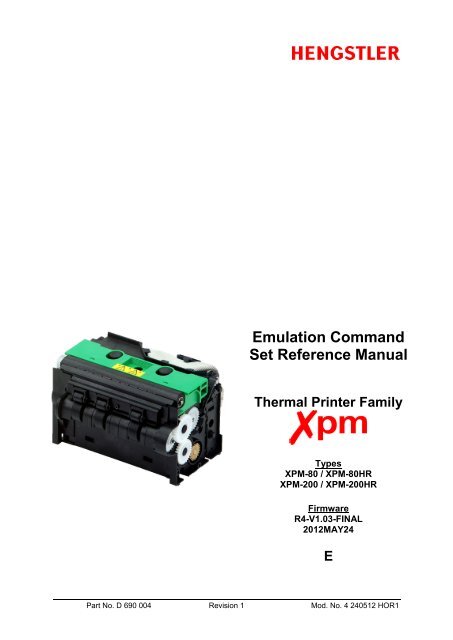
XPM <strong>Emulation</strong> <strong>Command</strong> <strong>Set</strong> <strong>Reference</strong>1 IntroductionThis XPM <strong>Emulation</strong> <strong>Command</strong> <strong>Set</strong> <strong>Reference</strong> describes the command set of the<strong>Hengstler</strong> XPM thermal printers. Please read this reference manual thoroughlybefore using the XPM and communicating with the printer.Comments:• Communication with the host is accomplished either through a USB or RS232 interface.• XPM printers can print graphic data with or without compression.• Burn time (“on” time of the thermal printhead) can be adjusted to control the printing intensity.• Drivers are available for easy operation by PC. The Windows XP driver contains an API foreasy integration to the host application.• Upload of firmware revisions can be accomplished with a tool that accompanies the WindowsXP driver.• Note that when data is sent from the external equipment to the XPM printer, all data must besent as binary data.• Note that the XPM series of printers use advanced printing and positioning features, allowingthe placement of images, bar codes, text, etc., anywhere on the printout. As a result, the XPMseries does not automatically wrap text that exceeds its margins. Proper design of print locationon the printout should eliminate the need for text wrapping.• When using RS232 communications, the question of whether handshaking is requiredsometimes occurs. XPM printers employ large buffers and, in many cases, will work withoutany handshaking at all. However, to ensure that there is no data loss and to optimizeperformance of your XPM printer, we recommend that hardware handshaking always beemployed and that the host queries the status of the XPM printer at appropriate times.Part No. D 690 004 Page 9 of 112 Mod.Nr. 4 240512 HOR1
XPM <strong>Emulation</strong> <strong>Command</strong> <strong>Set</strong> <strong>Reference</strong>2 Printer <strong>Command</strong> Overview (<strong>Emulation</strong>)Each command is explained using the following conventions:[Name] <strong>Command</strong> name[Function] Function of command[Code] Control code represented in hexadecimal or decimal notation.[X] 16 Hexadecimal notation (‘0’..’9’, ‘A’..’F’)[X] 10 Decimal notation (‘0’..’9’)[X] 2 Binary notation (‘0’..’1’)[Description] Explanation of command function2.1 Firmware Feature CodeThe XPM family of thermal printers is offered with either a Basic or an Advancedfirmware set. Some commands listed in this manual function only with the Advancedfirmware set, and are marked “Advanced Firmware <strong>Set</strong> only”.To determine if your printer has the Advanced or Basic firmware set, look at the shortprintout that is generated when paper is loaded. In the section under “PRINTER”,locate the field “FEATURE CODE”. This code shows 8 digits. If the 5 th digit is a “0”,then the printer has the advanced firmware set. If the 5 th digit is a “1”, then the printerhas the Basic firmware set. See example below.This “1” character indicates limited print speedFEATURE CODE : [00011000]This “1” character indicates basic firmware setPart No. D 690 004 Page 10 of 112 Mod.Nr. 4 240512 HOR1
XPM <strong>Emulation</strong> <strong>Command</strong> <strong>Set</strong> <strong>Reference</strong>2.2 <strong>Emulation</strong> <strong>Command</strong> <strong>Set</strong>The following commands are used when communicating with the printer controller. Allother commands are ignoredPart No. D 690 004 Page 11 of 112 Mod.Nr. 4 240512 HOR1
XPM <strong>Emulation</strong> <strong>Command</strong> <strong>Set</strong> <strong>Reference</strong>2.2.1 Horizontal tab TAB HT[Name]Horizontal tab[Function] This command moves the printing position to the next horizontal tab position.[Code] [09] 16[9] 10[Description]1. <strong>Command</strong> “HT” moves the printing position to the next tab position.2. The horizontal tab positions are set with command „ESC ‘D’ ”.3. If the next horizontal tab position is not set, the HT command is ignored.4. If the next horizontal tab position is outside the printing area, the printing position is shifted to thenext line.Part No. D 690 004 Page 12 of 112 Mod.Nr. 4 240512 HOR1
XPM <strong>Emulation</strong> <strong>Command</strong> <strong>Set</strong> <strong>Reference</strong>2.2.2 Line feed LF[Name][Function]Line feed[Code] [0A] 16This command prints the data already contained in the print buffer, then sets thenext-data receive position at the left most column on the next line.[10] 10[Description]1. <strong>Command</strong> “LF” prints the data already contained in the print buffer, then sets the next-datareceive position at the leftmost column on the next line.2. In the initial state, the line spacing is set to approx. 1/8 inch.3. When there is no data in the print buffer, only a line feed operation is executed.4. When different-height character typefaces are to be printed on the same line, these charactertypefaces are arranged so that their bottom ends are aligned at the same level.5. If line spacing during printing/line-feeding is shorter than the character height, a length equal tothe character height feeds the paper.Part No. D 690 004 Page 13 of 112 Mod.Nr. 4 240512 HOR1
XPM <strong>Emulation</strong> <strong>Command</strong> <strong>Set</strong> <strong>Reference</strong>2.2.3 Carriage Return CR[Name]Carriage Return[Function] This command resets the printing position to the leftmost column on the same line.[Code] [0D] 16[14] 10[Description]1. <strong>Command</strong> “CR” resets the printing position to the leftmost column on the same line. Please notethat it does not cause the line to print. Use the Line Feed (LF) command to print the current lineand advance to the next line.Part No. D 690 004 Page 14 of 112 Mod.Nr. 4 240512 HOR1
XPM <strong>Emulation</strong> <strong>Command</strong> <strong>Set</strong> <strong>Reference</strong>2.2.4 Form Feed (new page) FF FF[Name]Form Feed (new page)[Function] This command feeds paper by the specified page length.[Code] [0C] 16[12] 10[Description]1. The “FF” command prints the data already contained in the print buffer, after which it feedsforward to the end of form.2. The form length is defined with use of the Xpm-ConfigTool.3. When mark control is enabled, then this command feeds to the mark offset, which is defined withuse of the Xpm-ConfigTool.Part No. D 690 004 Page 15 of 112 Mod.Nr. 4 240512 HOR1
XPM <strong>Emulation</strong> <strong>Command</strong> <strong>Set</strong> <strong>Reference</strong>2.2.5 Character set and country code selection ESC ‘%’ [n][Name][Function]Character set and country code selectionThis command selects the character set and the country code[Code] [1B] 16 [25] 16 [n][Description][27] 10 [37] 10 [n]1. <strong>Command</strong> „ESC ‘%’ [n]“ selects the primary or secondary character set and the country codewithin this character set.2. Either character set can be changed by uploading a new character set to the printer using thesupplied font upload tool.3. Parameter [n] specifies character set and country code. The following figure shows therelationship between the bits of parameter [n] and character set and country code:Parameter [n], bit Value Printing mode(LSB)b0 – b2b3 – b7(MSB)0 Primary character set (default)1 Secondary character set2 – 7 Reserved for future use0 Country code disabled (default)1 USA2 France3 Germany4 U.K.5 Denmark 16 Sweden7 Italy8 Spain 19 Japan 110 Norway11 Denmark 212 Spain 213 Latin America14 Japan 215 - 31 Reserved for future use4. The country code characters are available from firmware version R2-V1.01f or up.5. The country code characters are positioned in row 9 and 10 of the primary and secondarycharacter set:Primary character setSecondary character setPart No. D 690 004 Page 16 of 112 Mod.Nr. 4 240512 HOR1
XPM <strong>Emulation</strong> <strong>Command</strong> <strong>Set</strong> <strong>Reference</strong>6. Note that from firmware version R2-V1.02f or up all character sets have been extended with 3additional rows.7. If a country code is enabled, then the ASCII characters indexes [23] 16 , [24] 16 , [40] 16 , [5B] 16 , [5C]16 , [5D] 16 , [5E] 16 , [60] 16 , [7B] 16 , [7D] 16 and [7E] 16 (all codes in HEX) are mapped tocorresponding characters in row 9 and 10 of the primary or secondary character set.8. The corresponding country characters for each country code are as follows:CharacterIndex (HEX)23 24 40 5B 5C 5D 5E 60 7B 7C 7D 7ECountryCode0 Disabled # $ @ [ \ ] ^ ` { | } ~1 USA # $ @ [ \ ] ^ ` { | } ~2 France # $ à ° ç § ^ ` é ù è ~3 Germany # $ § Ä Ö Ü ^ ` ä ö ü ~4 U.K. £ $ @ [ \ ] ^ ` { | } ~5 Denmark 1 # $ @ Æ Ø Ǻ ^ ` æ ø ǻ ~6 Sweden # ¤ É Ä Ö Ǻ Ü é ä ö ǻ ù7 Italy # $ @ ° \ é ^ ù ä ò è ì8 Spain 1 Pt $ @ ¡ Ñ ¿ ^ ` ˝ ñ } ~9 Japan 1 # $ @ [ ¥ ] ^ ` { | } ~10 Norway # ¤ É Æ Ø Ǻ Ü é æ ø ǻ ù11 Denmark 2 # $ É Æ Ø Ǻ Ü é æ ø ǻ ù12 Spain 2 # $ á ¡ ñ ¿ é ` í ñ ó ú13 Latin America # $ á ¡ ñ ¿ é Ü í ñ ó ú14 Japan 2 # $ @ [ ¥ ] ^ ` { | } ~9. The type of primary/secondary character set (e.g. 8x16, 12x24, 16x32, 20x40) required isselected with the print mode command (see command „ESC ’!’ ...”).Printing mode specification(command „ESC ‘!’ ...”, lower 4 bits)Primary character setSecondary character set08 x 16 08 x 16 08 x 1612 x 24 12 x 24 12 x 2416 x 32 16 x 32 16 x 3220 x 40 20 x 40 20 x 40Part No. D 690 004 Page 17 of 112 Mod.Nr. 4 240512 HOR1
XPM <strong>Emulation</strong> <strong>Command</strong> <strong>Set</strong> <strong>Reference</strong>2.2.6 Character size specification ESC ‘!’ [n][Name]Character size specification[Function] This command specifies character size for text output.[Code] [1B] 16 [21] 16 [n][27] 10 [33] 10 [n][Description]1. <strong>Command</strong> „ESC ‘!’ [n]“ specifies character size.2. The following figure shows the relationship between the bits of parameter [n] and character size:Parameter [n], bit Value Printing mode(LSB)b0 - b1[00] 2 08x16-dot character typeface[01] 2 12x24-dot character typeface[10] 2 16x32-dot character typeface[11] 2 20x40-dot character typefaceb2 - b3 [00] 2 No magnification[01] 2 2 X magnification[10] 2 3 X magnification[11] 2 4 X magnificationb4 0 Double width disabled1 Double width enabledb5 0 Double height disabledb6 – b7(MSB)1 Double height enabledReserved for future use; must be set to “0”3. When one line contains different-height character typefaces, the character typefaces arearranged so that their bottom ends are aligned at the same level.Part No. D 690 004 Page 18 of 112 Mod.Nr. 4 240512 HOR1
XPM <strong>Emulation</strong> <strong>Command</strong> <strong>Set</strong> <strong>Reference</strong>2.2.7 Black-on-white reversed printing specification GS ‘B’ [n][Name]Black-on-white reversed printing specification[Function] This command enables and disables black-on-white reversed printing.[Code] [1D] 16 [42] 16 [n][29] 10 [66] 10 [n][Description]1. <strong>Command</strong> „GS ‘B’ [n]“ Enables or disables black-on-white (reversed) printing.2. Permissible values of [n] are “0” and “1”.3. If n = 0, black-on-white reversed printing is off. If n = 1, black-on-white reverse printing is on.4. The default value for [n] is “0”.5. The command can be used in all character modes and all character sets.6. The line-spacing (line pitch) area does not appear in reverse format.7. A single text-line can contain both normal printed characters and reverse printed characters.8. No character spacing (except for character blanks, e.g. tabs, margins), appears reversed.Part No. D 690 004 Page 19 of 112 Mod.Nr. 4 240512 HOR1
XPM <strong>Emulation</strong> <strong>Command</strong> <strong>Set</strong> <strong>Reference</strong>2.2.8 1/6-inch line pitch setting ESC ‘2’[Name]1/6-inch line pitch setting[Function] This command sets the single line pitch to 1/6 inch.[Code] [1B] 16 [32] 16[27] 10 [50] 10[Description]1. <strong>Command</strong> „ESC ‘2’” sets single line pitch to 1/6 inch.2. Please note that “line pitch” is defined as the distance from the top of one character line to the topof the next character line.3. This command invalidates the line pitch previously set with command „ESC ‘3’ ...”.4. This command invalidates the line spacing previously set with the command „ESC ‘A’ ...”.Part No. D 690 004 Page 20 of 112 Mod.Nr. 4 240512 HOR1
XPM <strong>Emulation</strong> <strong>Command</strong> <strong>Set</strong> <strong>Reference</strong>2.2.9 Line pitch setting ESC ‘3’ [n][Name]Line pitch setting[Function] This command sets the single line pitch in dot lines.[Code] [1B] 16 [33] 16 [n][27] 10 [51] 10 [n][Description]1. <strong>Command</strong> „ESC ‘3’ [n]“ sets the single line pitch to n dot lines.2. Please note that “line pitch” is defined as the distance from the top of one character line to the topof the next character line.3. This command invalidates the line pitch previously set with command „ESC ‘2’”.4. This command invalidates the line spacing previously set command „ESC ‘A’ [n]“.5. Parameter [n] defines the line pitch in dot lines.6. Parameter [n] must match following conditions:[0] 10
XPM <strong>Emulation</strong> <strong>Command</strong> <strong>Set</strong> <strong>Reference</strong>2.2.10 Line spacing setting ESC ‘A’ [n][Name]Line spacing setting[Function] This command sets the line spacing to a specific amount of dot lines.[Code] [1B] 16 [41] 16 [n][27] 10 [65] 10 [n][Description]1. <strong>Command</strong> „ESC ‘A’ [n]“ sets the line spacing to [n] dot lines.2. Condition [0] 10 ≤ [n] ≤ [255] 10 must be satisfied.3. If this command is set two or more times for the same line, the last set line spacing is valid.4. When line pitch is set with command „ESC ‘3’” or „ESC ‘2’”, the line spacing set with thiscommand is invalidated.5. Please note that “line spacing” is defined as the distance from the bottom of one character line tothe top of the next character line. Note the difference between line pitch and line spacing:LinePitchLINE 1LINE 2LineSpacingPart No. D 690 004 Page 22 of 112 Mod.Nr. 4 240512 HOR1
XPM <strong>Emulation</strong> <strong>Command</strong> <strong>Set</strong> <strong>Reference</strong>2.2.11 Left margin specification GS ‘L’ [n] [m][Name][Function]Left margin specificationThis command sets the left margin.[Code] [1D] 16 [4C] 16 [n] [m][29] 10 [76] 10 [n] [m][Description]1. <strong>Command</strong> „GS ‘L’ [n] [m]“ specifies the left margin in dots.2. Both parameters [n] and [m] specify the left margin, whereas this margin is calculated as follows:“left margin” = [n] + [m] * [256] 10 .3. The range of parameter [n] is [0] 10 ≤ [n] ≤ [255] 10 .4. The range of parameter [m] is as follows.XPM-80 (203 dpi): [0] 10 ≤ [m] ≤ [2] 10XPM-200 (203 dpi): [0] 10 ≤ [m] ≤ [6] 10XPM-200HR (300 dpi): [0] 10 ≤ [m] ≤ [10] 105. If the result of the calculation [n] [m] * [256] 10 is greater than the number of dots in the dot row(640 for the XPM-80/203 dpi, 1680 for the XPM-200/203 dpi, 2592 for the XPM-200HR/300 dpi,),then this command will be ignored.Part No. D 690 004 Page 23 of 112 Mod.Nr. 4 240512 HOR1
XPM <strong>Emulation</strong> <strong>Command</strong> <strong>Set</strong> <strong>Reference</strong>2.2.12 Character spacing specification ESC SP [n][Name]Character spacing specification[Function] This command specifies the character spacing in dots.[Code] [1B] 16 [20] 16 [n][27] 10 [32] 10 [n][Description]1. <strong>Command</strong> „ESC SP [n]“ specifies the spacing between characters in dots.2. Parameter [n] specifies the number of blank dots between adjacent characters.3. Condition [0] 10 ≤ [n] ≤ [32] 10 must be satisfied.4. Initially the value for [n] is [0] 10 (no character spacing).Part No. D 690 004 Page 24 of 112 Mod.Nr. 4 240512 HOR1
XPM <strong>Emulation</strong> <strong>Command</strong> <strong>Set</strong> <strong>Reference</strong>2.2.13 Character underlining ESC ‘-‘ [n][Name][Function]Character underliningThis command turns character underlining on and off, and specifies the number ofdot rows to be used when underlining a character.[Code] [1B] 16 [2D] 16 [n][27] 10 [45] 10 [n][Description]1. <strong>Command</strong> „ESC ‘-‘ [n]“ controls character underlining and the number of dot rows used for theunderline.2. Parameter [n] specifies the number of dot rows to be used when underlining.3. Condition [0] 10 ≤ [n] ≤ [3] 10 must be satisfied; I.E., a maximum of three dot rows can be used forunderlining.4. The default value for [n] is [0] 10 (no underlining).5. Underlining remains in effect until a subsequent underline command changes the value.6. It is possible to mix underlining on a single line. For example, part of the line can be underlinedwith three dot rows, part with two, part with one, and part with none.Part No. D 690 004 Page 25 of 112 Mod.Nr. 4 240512 HOR1
XPM <strong>Emulation</strong> <strong>Command</strong> <strong>Set</strong> <strong>Reference</strong>2.2.14 Bold characters enable/disable ESC ‘E‘ [n][Name]Bold characters enable/disable[Function] This command enables/disables bold character printing[Code] [1B] 16 [45] 16 [n][27] 10 [69] 10 [n][Description]1. <strong>Command</strong> „ESC ‘E‘ [n]“ Enables or disables bold character printing.2. Bold characters are enabled when parameter [n] = [1] 10 , and disabled otherwise.3. Condition [0] 10 ≤ [n] ≤ [1] 10 must be satisfied.4. The default value for [n] is [0] 10 (bold characters disabled).Part No. D 690 004 Page 26 of 112 Mod.Nr. 4 240512 HOR1
XPM <strong>Emulation</strong> <strong>Command</strong> <strong>Set</strong> <strong>Reference</strong>2.2.15 Enable wide font printing ESC [F0] [07] [01] [n][Name][Function]Enable wide font printing (Note: Advanced Firmware <strong>Set</strong> only)This command enables/disables wide font printing with standard/ GB2312-Chinese/KS5601-Korean character sets.[Code] [1B] 16 [F0] 16 [07] 16 [01] 16 [n][27] 10 [240] 10 [7] 10 [1] 10 [n][Description]1. <strong>Command</strong> „ESC [F0] [07] [01] [n]“ Enables/disables wide font printing, where the wide font isrepresented by 7000 characters, each made up of 24X24 or 20X20 dots.2. If wide font printing is enabled, then each character in this font is represented by a specific 2 bytecode, which correlates to a specific wide font character. The selected wide font index specifieshow the two byte code is mapped onto an entry in the wide font.3. Four wide font indexes are available: standard 24X24, GB2312-Chinese 24X24, standard 20X20and KS5601-Korean 20X20. Wide font printing is automatically enabled if one of these indexes isselected.4. For both standard indexes, each two consecutive bytes that exceed [E0] 16 [00] 16 are regarded aswide font character code references, whereas the corresponding character in the wide font isselected by subtracting [E0] 16 [00] 16 (e.g. [E0] 16 [00] 16 is the 1 st character, [E0] 16 [01] 16 is the 2 ndcharacter, ..., [E0] 16 [FF] 16 is the 256 th character, [E1] 16 [00] 16 is the 257 th character, etc.).5. For the GB2312-Chinese index, each two consecutive bytes that exceed [A0] 16 [00] 16 are regardedas wide font character code references, whereas the corresponding character in the wide font isselected according to the “GB2312” Simplified Chinese character map. The GB2312-Chineseindex operates with a special preprocessed GB2312 type font only.6. For the KS5601-Korean index, each two consecutive bytes that exceed [A0] 16 [00] 16 are regardedas wide font character code references, whereas the corresponding character in the wide font isselected according to the “KS5601” Korean character map. The KS5601-Korean index operateswith a special preprocessed KS5601 type font only.7. Bytes that are not regarded as wide font character code references are regarded as normal singlebyte references in the internal/external character sets. If received, then the correspondinginternal/external character is printed.8. Escape commands that affect the internal/external character set (e.g. print mode) also affect thewide font printing (e.g. double width, 3X magnification, etc.).9. The default wide font index is stored in flash memory. Its value can be wide font disabled, widefont enabled with standard index or wide font enabled with Chinese index.10. The valid range for parameter [n] is [0] 10 ≤ [n] ≤ [4] 10 or [7] 10 . All other values are ignored. Themeaning of each value of [n] is as follows.n Result0 Wide font printing disabled1 Wide font printing enabled with standard 24 x 24 index2 Wide font printing enabled with GB3212 Chinese 24 x 24 index3 Wide font printing enabled with standard 20 x 20 index4 Wide font printing enabled with KS5601-Korean 20 x 20 index7 Wide font printing index is reset to its default value, which is stored in flash memory.11. The printer status information that is printed after paper insertion also contains information on theselected wide font index, provided that wide font printing is enabled.Part No. D 690 004 Page 27 of 112 Mod.Nr. 4 240512 HOR1
XPM <strong>Emulation</strong> <strong>Command</strong> <strong>Set</strong> <strong>Reference</strong>2.2.16 Form length setting “ESC ‘C’ [n1] [n2][Name][Function]Form length settingThis command sets the form length to a specific length.[Code] [1B] 16 [43] 16 [n1] [n2][Description][27] 10 [67] 10 [n1] [n2]1. <strong>Command</strong> „ESC ‘C’ [n1] [n2]“ sets the form length to a specific length.2. Parameter [n1] and [n2] represents the form length in 1/10 mm. (For example, “1234” = 123.4mm).3. Parameter [n1] and [n2] form a 16-bit, unsigned integer with a valid range up to 65,535.Parameter [n1] is the MSB and parameter [n2] the LSB of this value.4. With this command it is possible to represent a length of approx. 6.5 meters of paper (approx. 21feet). Care should be taken to avoid the paper wasted associated with accidentally setting thepage length so long.Part No. D 690 004 Page 28 of 112 Mod.Nr. 4 240512 HOR1
XPM <strong>Emulation</strong> <strong>Command</strong> <strong>Set</strong> <strong>Reference</strong>2.2.17 End of page ESC [F0] [06] [x] [n] [m][Function]This command signals the end of page, prints the buffer, initiates cutting (ifdesired), and allows the transmission of a parameter byte to be echoed back bythe printer after printing is completed[Code] [1B] 16 [F0] 16 [06] 16 [x] [n] [m][29] 10 [240] 10 [6] 10 [x] [n] [m][Description]1. <strong>Command</strong> „ESC [F0] [06] [x] [n] [m]“ signals the end of page, prints the buffer, initiates cutting (ifdesired), and allows the transmission of a parameter byte to be echoes back by the printer afterprinting is completed.2. Permissible values of [x] are “1” and “2”.If x = 1, then the command is to be used without a parameter byte to be echoed back. In thiscase, the syntax is [1B] 16 [F0] 16 [06] 16 [01] [n].If x = 2, then the command is to be used with a parameter byte. The syntax then is[1B] 16 [F0] 16 [06] 16 [02] [n] [m].3. Parameter [n] is broken into a most significant Nibble (MSN) and a least significant Nibble (LSN).The LSN controls cutting, as follows, and has the permissible values of “0”, “1” or “2”.If LSN[n] = 0, no cut will occur after printing.If LSN[n] = 1, a partial cut will occur after printing (if available).If LSN[n] = 2, a full cut will occur after printing (if available).The MSN of n determines whether the command is interpreted as an “End of Print” or an “End ofForm”.If MSN [n] = 0, the command is treated as an “End of Print”.If MSN [n] = 1, the command is treated as an “End of Form”.4. “End of Print” acts as follows. (Please note that the “End of Print” command generally causesimmediate movement of the paper and execution of the cut, as commanded. Also please notethat anytime the “Top of Page” is set, the “Top of Form” is also set to the same location. Whenthe “Top of Form” is set directly, it has no impact on the “Top of Page” location.)If End of Print is sent with no cut command, the current location will be set as “Top of Page”.If End of Print is sent with a partial cut command, this location will be set as “Top of Page”, thepaper will be advanced to the cut line, and a partial cut will occur. There will be no retracting tothe park position because the partially cut paper is still attached to the paper roll.If End of Print is sent with a full cut command, this location will be set as “Top of Page”, the paperwill be advanced to the cut line, and a full cut will occur. The paper will then be retracted to thepark position.5. “End of Form” acts as follows. (Please note that the “End of Form” command generally causes nomovement of the paper.)If End of Form is sent with no cut command, the current location will be set as “Top of Form”.If End of Form is sent with a partial cut command, this location will be set as “Top of Form” and apartial cut will occur when this location moves under the cut line due to other printing commands(additional data printed, line feeds, etc.).If End of Form is sent with a full cut command, this location will be set as “Top of Page”, and a fullcut will occur when this location moves under the cut line due to other printing commands(additional data printed, line feeds, etc.).6. The default value for [n] is “0”.7. Permissible values for [m] are in the range [0] 10
XPM <strong>Emulation</strong> <strong>Command</strong> <strong>Set</strong> <strong>Reference</strong>9. The status parameter [m] can also be set via the <strong>Set</strong> Status Parameter command. See the <strong>Set</strong>Status Parameter section for a more detailed discussion of how this parameter is used.Part No. D 690 004 Page 30 of 112 Mod.Nr. 4 240512 HOR1
XPM <strong>Emulation</strong> <strong>Command</strong> <strong>Set</strong> <strong>Reference</strong>2.2.18 Horizontal tab positions ESC D [d1] ... [dn] NUL[Name][Function]<strong>Set</strong>s Horizontal tab positionsThis command sets one or more horizontal tab positions or deletes all tabpositions.[Code] [1B] 16 [44] 16 [d1] .. [dn] [00] 16[27] 10 [68] 10 [d1] .. [dn] [0] 10[Description]1. <strong>Command</strong> „ESC ‘D’ [d1] ... [dn] NUL” sets one or more tab positions, which are used by thehorizontal tab command “HT”.2. The following conditions must be satisfied for the values of d1, d2, etc. (tab position).XPM-80 / 203 dpi Printer: [1] 10 ≤ [d] ≤ [80] 10XPM-200 / 203 dpi Printer: [1] 10 ≤ [d] ≤ [200] 10XPM-200HR / 300 dpi Printer: [1] 10 ≤ [d] ≤ [200] 103. The maximum number of tabs that can be set it 32. Therefore, the condition [1] 10 ≤ [n] ≤ [32] 10must be satisfied. Any data sent after the 32 nd horizontal tab position will be treated as ordinarydata.4. The horizontal tab position is set to [d] x 8 dots distant from the head of the line in the printingarea.5. When the horizontal tab is set with this command, all horizontal tab positions previously set aredeleted. Therefore, to add a tab, it is necessary to resend all the previous tab locations along withthe new tab location.6. The [d] values must be entered in ascending order, and the data string must end with NUL ([0] 10 ).7. All horizontal tab positions can be deleted with command „ESC ‘D’ NUL”.8. When the power to the printer is cycled or the printer is reset, the horizontal tab positions are setto intervals of 8 default characters as selected during initialization.Part No. D 690 004 Page 31 of 112 Mod.Nr. 4 240512 HOR1
XPM <strong>Emulation</strong> <strong>Command</strong> <strong>Set</strong> <strong>Reference</strong>2.2.19 Forward paper feed ESC ‘J’ [n][Name]Forward paper feed[Function] This command feeds paper in the forward direction.[Code] [1B] 16 [4A] 16 [n][27] 10 [74] 10 [n][Description]9. <strong>Command</strong> „ESC ‘J’ [n]“ feeds paper in the forward direction by [n] dot lines.10. Condition [0] 10 ≤ [n] ≤ [255] 10 must be satisfied.11. When there is data in the print buffer, this data will be printed first, and then the paper will be fedin the forward direction as specified by [n].12. If parameter [n] equals [0] 10 , the data contained in the buffer is printed but paper is not fed.Part No. D 690 004 Page 32 of 112 Mod.Nr. 4 240512 HOR1
XPM <strong>Emulation</strong> <strong>Command</strong> <strong>Set</strong> <strong>Reference</strong>2.2.20 Forward n-line feed ESC ‘d’ [n][Name][Function]Forward n-line feedThis command prints the data and feeds a line, then feeds the paper by [n]character lines.[Code] [1B] 16 [64] 16 [n][27] 10 [100] 10 [n][Description]1. <strong>Command</strong> „ESC ‘d’ [n]“ feeds paper by a character line count specified with parameter [n].2. Condition [0] 10 ≤ [n] ≤ [255] 10 must be satisfied.3. After [n] lines are fed, the next print position is located at the left edge on the line.4. When there is data in the print buffer, the data contained in the buffer is printed upon receipt ofthis command, after which paper is fed by [n] character lines.5. Pitch or spacing is also taken into account by this command.Part No. D 690 004 Page 33 of 112 Mod.Nr. 4 240512 HOR1
XPM <strong>Emulation</strong> <strong>Command</strong> <strong>Set</strong> <strong>Reference</strong>2.2.21 <strong>Set</strong> position ESC ‘$’ [n1] [n2] [m1] [m2][Name][Function]<strong>Set</strong> positionThis command specifies the position at which predefined objects such as graphics,text, bar codes, etc. will print.[Code] [1B] 16 [24] 16 [n1] [n2] [m1] [m2][27] 10 [36] 10 [n1] [n2] [m1] [m2][Description]1. <strong>Command</strong> „ESC ‘$’ [n1] [n2] [m1] [m2]“ specifies the position at which a predefined object, suchas graphics, text, bar codes, etc., will be printed.2. Parameters n1 and n2 define the X coordinate of the upper, left-hand corner of where the objectwill print, defined in tenths of a mm (0.1 mm). n1 is the MSB, while n2 is the LSB. The Xcoordinate is therefore defined as n1 * [256] 10 n2, in tenths of a mm.3. Parameters m1 and m2 define the Y coordinate of the upper, left-hand corner of where the objectwill print, defined in tenths of a mm (0.1 mm). m1 is the MSB, while m2 is the LSB. The Ycoordinate is therefore defined as m1 * [256] 10 m2, in tenths of a mm.4. The ranges of the four parameters are as follows. Also please note that if the value of n1 * 256 +n2 exceeds 800 for an XPM-80 / 203 dpi, 2000 for an XPM-200 / 203 dpi or 2000 for an XPM-200HR / 300 dpi, the upper left corner of the printing start position will be off the paper.5. Similarly, please note that the value of m1 * 256 + m2 can become quite large, positioning theupper left corner of the print start position over one meters down the paper. Care should be takento avoid this situation accidentally.ParameterValid Rangesn1 [0] 10 ≤ [n1] ≤ [255] 10n2 [0] 10 ≤ [n2] ≤ [255] 10m1 [0] 10 ≤ [m1] ≤ [40] 10m2 [0] 10 ≤ [m2] ≤ [255] 106. Note the red dot in the image below. This represents the position as defined by this commandand shows where the text, image, bar code, etc. will be oriented with regard to that position withdifferent degrees of rotation.Part No. D 690 004 Page 34 of 112 Mod.Nr. 4 240512 HOR1
XPM <strong>Emulation</strong> <strong>Command</strong> <strong>Set</strong> <strong>Reference</strong>2.2.22 Text, image, bar code and character rotationESC ‘V’ [n] [m][Name][Function]Text, image, bar code and character rotation(Note: Advanced Firmware <strong>Set</strong> only)This command specifies the rotation angle for text, images, bar codes andcharacters.[Code] [1B] 16 [56] 16 [n] [m][Description][27] 10 [86] 10 [n] [m]1. <strong>Command</strong> „ESC ‘V’ [n] [m]“ specifies the rotation angle for:- text rotation: 0°, 90°, 180° and 270°- image rotation: 0°, 90°, 180° and 270°- bar code rotation: 0°, 90°, 180° and 270°- character rotation: 0°, 90°, 180° and 270°2. Parameter [n] defines what is affected by the rotation:Parameter [n]Rotation[0] 10 Text[1] 10 Images[2] 10 Bar Codes[3] 10 Characters3. Parameter [m] defines the angle of rotation:Parameter [m]Angle of rotation[0] 10 0°[1] 10 90°[2] 10 180°[3] 10 270°4. All objects can be rotated in all available directions, whereas the left upper position is defined bythe “<strong>Set</strong> position” command „ESC $ [n1] [n2] [m1] [m2]“.5. Text rotation causes the entire text to be rotated as a unit.6. Character rotation causes only the individual characters to be rotated, not the entire text.7. All bar code settings (height, width, magnification) are effective when printing bar codes.Part No. D 690 004 Page 35 of 112 Mod.Nr. 4 240512 HOR1
XPM <strong>Emulation</strong> <strong>Command</strong> <strong>Set</strong> <strong>Reference</strong>2.2.23 Start block rotation ESC [F0] [0B] [01] [n][Name][Function]Start block rotation (Note: Advanced Firmware <strong>Set</strong> only)This command signifies that all commands sent after it are to be treated as a singleblock and rotated intact as specified below.[Code] [1B] 16 [F0] 16 [0B] 16 [01] 16 [n][Description][27] 10 [240] 10 [11] 10 [1] 10 [n]1. <strong>Command</strong> „ESC [F0] [0B] [01] [n]“ signifies that all commands and data sent after it, until receiptof the End Block Rotation command, are to be treated as a single block and rotated intact asspecified below.2. Parameter [n] defines the angle of rotation for the entire block:Parameter [n]Angle of rotation[FF] 16Disabled[00] 16 0°[01] 16 90°[02] 16 180°[03] 16 270°3. The upper left corner of the block is the key when rotating, and the block will start as far to theupper left as defined by the rotation of the objects sent.The “T” in “The” is theupper left hand cornerbefore rotation.The “T” in “The” is the upper left hand corner after rotation.4. Please note that all commands, including Line Feed, are stored and are used only to position andformat the data to be printed. Once this command has been sent, there will be no printing untilreceipt of the End Block Rotation command, which will cause the entire block to be printed.5. The commands “Print uncompressed graphics” and “Print RLE8 compressed graphics” areignored by the Start Block Rotation command.Part No. D 690 004 Page 36 of 112 Mod.Nr. 4 240512 HOR1
XPM <strong>Emulation</strong> <strong>Command</strong> <strong>Set</strong> <strong>Reference</strong>2.2.24 End block rotation ESC [F0] [0C] [00][Name][Function]End block rotation (Note: Advanced Firmware <strong>Set</strong> only)This command closes the Start Block Rotation command and immediately causesprinting of the data sent after the Start Block Rotation command was received.[Code] [1B] 16 [F0] 16 [0C] 16 [00] 16[Description][27] 10 [240] 10 [12] 10 [0] 101. <strong>Command</strong> „ESC [F0] [0C] [00]“ Ends the transmission of data to be printed as a block that wasinitiated by the Start Block Rotation command and causes it to be printed.Part No. D 690 004 Page 37 of 112 Mod.Nr. 4 240512 HOR1
XPM <strong>Emulation</strong> <strong>Command</strong> <strong>Set</strong> <strong>Reference</strong>2.2.25 Printer reset (software) ESC ‘@’[Name]Printer reset (software)[Function] This command initializes/resets the printer.[Code] [1B] 16 [40] 16[27] 10 [64] 10[Description]1. <strong>Command</strong> „ESC ‘@’” resets the printer settings to their default values.2. “Default” is defined as the status of the printer after initial power up.3. <strong>Command</strong> „ESC ‘@’” prints the data contained in the print buffer before resetting.Part No. D 690 004 Page 38 of 112 Mod.Nr. 4 240512 HOR1
XPM <strong>Emulation</strong> <strong>Command</strong> <strong>Set</strong> <strong>Reference</strong>2.2.26 Printer reset (hardware) ESC [F2] [03] [00][Name]Printer reset (hardware)[Function] This command performs a hard reset of the printer by resetting the hardware.[Code] [1B] 16 [F2] 16 [03] 16 [00] 16[27] 10 [142] 10 [03] 10 [00] 10[Description]1. <strong>Command</strong> „ESC [F2] [03] [00]“ performs a hardware reset of the printer.2. When command „ESC [F2] [03] [00]“ is executed, the printer does not print the buffer beforeresetting. All data in the buffer is lost. All conditions are returned to those that would exist if thepower were removed and then restored.Part No. D 690 004 Page 39 of 112 Mod.Nr. 4 240512 HOR1
XPM <strong>Emulation</strong> <strong>Command</strong> <strong>Set</strong> <strong>Reference</strong>2.2.27 Print stored image data GS ‘’‘ [m] [n][Name]Print stored image data (Note: Advanced Firmware <strong>Set</strong> only)[Function] This command causes stored image data to be printed.[Code] [1D] 16 [27] 16 [m] [n][29] 10 [39] 10 [m] [n][Description]1. <strong>Command</strong> „GS ‘’‘ [m] [n]“ causes image data, stored in flash memory, to be printed.2. Parameter [m] specifies the identification number of the stored image. (The first stored image isidentification no. 1, the second ID no. 2, etc.)3. The range of parameter [m], the identification number, is [1] 10 ≤ [m] ≤ [255] 10 .4. If there is no registered image stored for a transmitted identification number, then the command isignored.5. Parameter [n] specifies the print mode, as follows:Parameter [n] Print mode Caption[0] 10 Normal The stored image data is printed in the original stored size.[1] 10 Double width The stored image data is printed in double width.[2] 10 Double height The stored image data is printed in double height.[3] 10 Double width andheightThe stored image data is printed in double width and height.6. Use of values for Parameters [m] and [n] other than as described above will cause the commandto be ignored.7. Images can be created and stored in the XPM printer by using the tools that come with the XPMprint driver.Part No. D 690 004 Page 40 of 112 Mod.Nr. 4 240512 HOR1
XPM <strong>Emulation</strong> <strong>Command</strong> <strong>Set</strong> <strong>Reference</strong>2.2.28 Bar code bar width setting GS ‘e’ [n] [m][Name]Bar code bar width setting[Function] This command sets the width of the bar code narrow and wide bars.[Code] [1D] 16 [65] 16 [n] [m][29] 10 [101] 10 [n] [m][Description]1. <strong>Command</strong> „GS ‘e’ [n] [m]“ defines the width of the bar code bars.2. The bars in a one-dimensional bar code can be wide or narrow and black or white.NARROW BLACK BARNARROW WHITE BARWIDE BLACK BARWIDE WHITE BARparameter „n“parameter „n“parameter „mn“parameter „mn“3. Parameter [n] specifies the width of a narrow white/black bar in dots.4. Parameter [m] specifies the width of a wide white/black bar in dots.5. When the bar code selected does not consist of wide bars and/or narrow bars, the value ofparameter [n] is set as the minimum width.6. The initial value of parameter [n] is [2] 10 .7. The initial value of Parameter [m] is [6] 10 .8. The following conditions must be satisfied:[1] 10 ≤ [n] ≤ [255] 10 and [1] 10 ≤ [m] ≤ [255] 10Part No. D 690 004 Page 41 of 112 Mod.Nr. 4 240512 HOR1
XPM <strong>Emulation</strong> <strong>Command</strong> <strong>Set</strong> <strong>Reference</strong>2.2.29 Bar code height setting GS ‘h’ [n][Name]Bar code height setting[Function] This command sets the height of a bar code in dots.[Code] [1D] 16 [68] 16 [n][29] 10 [104] 10 [n][Description]1. <strong>Command</strong> „GS ‘h’ [n]“ defines the height of a bar code.2. Parameter [n] specifies the height of the bar code in dots.3. The following conditions must be satisfied:[1] 10 ≤ [n] ≤ [255] 10 .4. The default value of parameter [n] is [60] 10 .Part No. D 690 004 Page 42 of 112 Mod.Nr. 4 240512 HOR1
XPM <strong>Emulation</strong> <strong>Command</strong> <strong>Set</strong> <strong>Reference</strong>2.2.30 Bar code width magnification setting GS w [n][Name]Bar code width magnification setting[Function] This command sets the width magnification for a bar code.[Code] [1D] 16 [77] 16 [n][29] 10 [109] 10 [n][Description]1. <strong>Command</strong> „GS w [n]“ specifies the width magnification of a one-dimensional bar code bymultiplying the dot width of the narrow and wide bars by a specified integer value.2. Parameter [n] specifies the horizontal magnification of a bar code.3. The following conditions must be satisfied:[1] 10 ≤ [n] ≤ [4] 10 .4. The default value of parameter [n] is [1] 10 .5. The widths of the narrow and wide bars (black and white) are multiplied by [n].6. This command is ignored two-dimensional bar codes.Part No. D 690 004 Page 43 of 112 Mod.Nr. 4 240512 HOR1
XPM <strong>Emulation</strong> <strong>Command</strong> <strong>Set</strong> <strong>Reference</strong>2.2.31 Bar code printing GS ‘k’ [m] [n] [d1] ... [dn][Name][Function]Bar code printingThis command selects a one dimensional bar code type and prints a onedimensional bar code.[Code] [1D] 16 [6B] 16 [m] [n] [d1] ... [dn][29] 10 [107] 10 [m] [n] [d1] ... [dn][Description]1. <strong>Command</strong> „GS ‘k’ [m] [n] [d1] ... [dn]“ selects a bar code type, supplies the data to be encodedand prints a bar code. The XPM printer will determine and print the bar code based on the datasent to it for encoding. The XPM is also capable of printing any bar code of appropriate resolutionsent to it as a graphics file. For printing of two dimensional bar codes, see “2D Bar codeconfiguration” and “2D Bar code printing”.2. Parameter [m] specifies the type of bar codes to be printed, which can be UPCA, UPCE, EAN13,EAN8, Code39, ITF (also called “Interleaved Two of Five”), Codabar, Code 128.3. The command configuration, code, definition area, and certain other conditions depend onparameter [m].4. Parameter [n] specifies the number of characters to be encoded by the bar code, which dependson the type of bar code.5. If the print data generates a bar code wider than will fit on one line, the excess portion of the barcode will print on the next line.6. Bar code height will be determined by the bar code height setting GS h [n], regardless of the linespacing set with the ESC 2 or ESC 3 commands.7. When printing an ITF bar code with parameter [m] = [70] 10 , the checksum digit must be calculatedby the customer and transmitted as part of the data. See “Restrictions and Notes Regarding ITFBar Codes” below for details on the algorithm and other ITF restrictions.8. When one line contains both a bar code and characters to be printed, the bottom of thesecharacters and the bottom of the bar code are aligned.9. Two or more bar codes cannot be contained on the same line. If this GS command is receivedwhen there is a bar code in the print buffer, the data contained in the print buffer is automaticallyprinted, after which the new command is accepted.Parameter[m]Type of Bar codeNumber of bar codecharactersValue of parameter[d1] ... [dn][41] 16 UPCA [11] 10
XPM <strong>Emulation</strong> <strong>Command</strong> <strong>Set</strong> <strong>Reference</strong>12. Restrictions and notes regarding EAN13:- if n is [12] 10 ,then the XPM printer will calculate the checksum.13. Restrictions and notes regarding Code 39:- The first and last characters must be ‘*’ (required by code 39 syntax).14. Restrictions and notes regarding ITF:• Only the digits 0 – 9 can be encoded by ITF, and they are sent as ASCII characters• ITF bar code must have an even number of digits, including the checksum• The last digit in the ITF bar code is the checksum.• The ITF checksum is calculated as follows.d 1 x 3 d 2 x 1 d 3 x 3 d 4 x 1 d n-1 x 3 = ZChecksum = 10 – (Z MOD 10)Example:ITF barcode = 123456789Z = 1 x 3 2 x 1 3 x 3 4 x 1 5 x 3 6 x 1 7 x 3 8 x 1 9 x 3 = 95Checksum = 10 – (95 MOD 10) = 10 – 5 = 5So, if manually transmitting the entire bar code with checksum, one should send 1234567895.15. Restrictions and notes regarding Code 128.- There are three subset of Code128 (Code128A, Code128B and Code128C).- The start character specifies which character set to be used.- The start character must be either 103 (subset A), 104 (subset B), 105 (subset C).The following table shows the value encoded for data (d) depending upon which subset isselected.Code128 bar code tabledata‘d’subsetAsubsetBsubsetCdata‘d’subsetAsubsetBsubsetC[0] 10 Space Space 0 [52] 10 T T 52[1] 10 ! ! 1 [53] 10 U U 53[2] 10 “ “ 2 [54] 10 V V 54[3] 10 # # 3 [55] 10 W W 55[4] 10 $ $ 4 [56] 10 X X 56[5] 10 % % 5 [57] 10 Y Y 57[6] 10 & & 6 [58] 10 Z Z 58[7] 10 ‘ ‘ 7 [59] 10 [ [ 59[8] 10 ( ( 8 [60] 10 \ \ 60[9] 10 ) ) 9 [61] 10 ] ] 61[10] 10 * * 10 [62] 10 ^ ^ 62[11] 10 + + 11 [63] 10 _ _ 63[12] 10 , , 12 [64] 10 NUL ‘ 64[13] 10 - - 13 [65] 10 SOH a 65[14] 10 . . 14 [66] 10 STX b 66[15] 10 / / 15 [67] 10 ETX c 67[16] 10 0 0 16 [68] 10 EOT d 68[17] 10 1 1 17 [69] 10 ENQ e 69[18] 10 2 2 18 [70] 10 ACK f 70[19] 10 3 3 19 [71] 10 BEL g 71[20] 10 4 4 20 [72] 10 BS h 72[21] 10 5 5 21 [73] 10 HT i 73[22] 10 6 6 22 [74] 10 LF j 74Part No. D 690 004 Page 45 of 112 Mod.Nr. 4 240512 HOR1
XPM <strong>Emulation</strong> <strong>Command</strong> <strong>Set</strong> <strong>Reference</strong>[23] 10 7 7 23 [75] 10 VT k 75[24] 10 8 8 24 [76] 10 FF l 76[25] 10 9 9 25 [77] 10 CR m 77[26] 10 : : 26 [78] 10 SO n 78[27] 10 ; ; 27 [79] 10 SI o 79[28] 10 < < 28 [80] 10 DLE p 80[29] 10 = = 29 [81] 10 DC1 q 81[30] 10 > > 30 [82] 10 DC2 r 82[31] 10 ? ? 31 [83] 10 DC3 s 83[32] 10 @ @ 32 [84] 10 DC4 t 84[33] 10 A A 33 [85] 10 NAK u 85[34] 10 B B 34 [86] 10 SYN v 86[35] 10 C C 35 [87] 10 ETB w 87[36] 10 D D 36 [88] 10 CAN x 88[37] 10 E E 37 [89] 10 EM y 89[38] 10 F F 38 [90] 10 SUB z 90[39] 10 G G 39 [91] 10 ESC { 91[40] 10 H H 40 [92] 10 FS | 92[41] 10 I I 41 [93] 10 GS } 93[42] 10 J J 42 [94] 10 RS ~ 94[43] 10 K K 43 [95] 10 US DEL 95[44] 10 L L 44 [96] 10 FNC3 FNC3 96[45] 10 M M 45 [97] 10 FNC2 FNC2 97[46] 10 N N 46 [98] 10 SHIFT SHIFT 98[47] 10 O O 47 [99] 10 Code C Code C 99[48] 10 P P 48 [100] 10 Code B FNC 4 Code B[49] 10 Q Q 49 [101] 10 FNC 4 Code A Code A[50] 10 R R 50 [102] 10 FNC 1 FNC 1 FNC1[51] 10 S S 51Part No. D 690 004 Page 46 of 112 Mod.Nr. 4 240512 HOR1
XPM <strong>Emulation</strong> <strong>Command</strong> <strong>Set</strong> <strong>Reference</strong>2.2.32 Bar code text subtitle setting ESC [F0] [08] [01] [n][Name][Function]Bar code text subtitle settingThis command allows enabling or disabling of the bar code text subtitle[Code] [1B] 16 [F0] 16 [08] 16 [ 01] 16 [n][27] 10 [240] 10 [8] 10 [ 1] 10 [n][Description]1. <strong>Command</strong> „ESC [F0] [08] [01] [n]“ Enables/disables bar code text subtitling and specifies it’sappearance.2. Parameter [n] specifies bar code text subtitling enabled/disabled, font size 8x16/12x24 and fontsource primary/secondary character set.Subtitle FontsSize Primary Font Secondary Font8x16 [01] 16 [09] 1612x24 [03] 16 [0B] 1616x32 [05] 16 [0D] 1620x40 [07] 16 [0F] 163. Parameter [n] has following bit map:Bit Status Caption0 Bar Code Plain Text Subtitle 0: Disabled 1: Enabled1-2 Font size 00: 08x16, 01: 12x24, 10: 16x32, 11: 20x403 Font source 0: Primary 1: Secondary4-7 Reserved 0 (these values should always be set to “0”)4. Bar code text subtitling is disabled by default.5. Bar code text subtitling is not available when bar code rotation is enabled.6. The bar code text subtitling may be unreadable or incorrect if the bar code dimension exceedsthe paper width.7. Since the internal primary or secondary font is used for bar code text subtitling, a replacement ofthe default fonts might result in an incorrect subtitling.Part No. D 690 004 Page 47 of 112 Mod.Nr. 4 240512 HOR1
XPM <strong>Emulation</strong> <strong>Command</strong> <strong>Set</strong> <strong>Reference</strong>2.2.33 2D Bar code configuration ESC [F0] [09] [07] [n1] ... [n7][Name]2D Bar code configuration (Note: Advanced Firmware <strong>Set</strong> only)[Function] This command selects a 2D bar code and sets the conditions for printing it.[Code] [1B] 16 [F0] 16 [09] 16 [07] 16 [n1] ... [n7][27] 10 [240] 10 [9] 10 [7] 10 [n1] ... [n7][Description]1. <strong>Command</strong> „ESC [F0] [09] [07] [n1] ... [n7]“ selects a two-dimensional (2D) bar code type and setsthe conditions to be used for printing it. This command does not initiate the printing of 2D barcode itself. See “2D Bar code printing” for the details on printing the bar code itself. The XPMprinter will determine and print the bar code based on the settings from this command and thedata sent to it for encoding from the “2D Bar code printing” command. The XPM is also capable ofprinting any bar code of appropriate resolution sent to it as a graphics file.2. Parameter [n1] specifies the type of 2D bar code to be printed. At present, the only valid selectionis “0”, which specifies a PDF417 bar code. Other 2D bar codes may be added in the future.3. Parameter [n2] specifies the 2D bar code style.Parameter [n2] Style0 Normal style1 Truncated style; no stop pattern or right row indicator4. Parameter [n3] specifies the ECC-error correction level. The valid range is [0] 10 ≤ [n3] ≤ [8] 10 ,where 0 = least error correction and 8 = most error correction. ECC-error correction is intended toallow the bar code to be read even when there is damage to it, such as a line being drawn acrossit or part of it being torn or destroyed. The more error correction that is used, the moreredundancy exists in the data and the larger the bar code is. Therefore, selection of thisparameter is a tradeoff between greater readability when damaged and smaller size.5. Parameter [n4] specifies the magnification range of the bar code. The valid range is [1] 10 ≤ [n4] ≤[4] 10 . The default value is “1”.6. Parameter [n5] specifies the height to be used when setting the bar code’s aspect ration. Thevalid range is [1] 10 ≤ [n5] ≤ [255] 10 .7. Parameter [n6] specifies the width to be used when setting the bar code’s aspect ration. The validrange is [1] 10 ≤ [n5] ≤ [255] 10 .8. Additionally, the ratio of [n5]/[n6] must fall in the range of 0.1 to 10.0. The default aspect ratio is1:2.9. Parameter [n7] specifies the height of the smallest module (mark) in the 2D bar code.10. Once the above data has been transmitted, use the command „ESC [F0] [0A] [n] [d1] ... [dn-1]“from the “2D Bar code printing” section to print 2D bar codes.Part No. D 690 004 Page 48 of 112 Mod.Nr. 4 240512 HOR1
XPM <strong>Emulation</strong> <strong>Command</strong> <strong>Set</strong> <strong>Reference</strong>2.2.34 2D Bar code printing ESC [F0] [0A] [n] [d1] ... [dn][Name][Function]2D Bar code printing (Note: Advanced Firmware <strong>Set</strong> only)This command encodes and prints a 2D bar code whose configuration has alreadybeen determined.[Code] [1B] 16 [F0] 16 [0A] 16 [n] [d1] ... [dn][27] 10 [240] 10 [10] 10 [n] [d1] ... [dn][Description]1. <strong>Command</strong> „ESC [F0] [0A] [n] [d1] ... [dn]“ Encodes and prints a 2D bar code whose configurationhas already been determined. This command does not configure the 2D bar code itself. See “2DBar code configuration” for the details on configuring the 2D bar code. The XPM printer willdetermine and print the bar code based on the settings from the “2D Bar code configuration”command and the data sent to it for encoding by this command. The XPM is also capable ofprinting any bar code of appropriate resolution sent to it as a graphics file.2. Parameter [n] specifies the number of bytes to be encoded, plus itself. For example, if there are 8bytes of actual data to be encoded, n = 9. [d1] [dn] is the actual data to be encoded in the 2Dbar code. If there are fewer than 255 bytes of data to be encoded, the bar code will print afterreceipt of the last data byte.3. If parameter [n] = [256] 10 , then there are 255 bytes of data to be encoded. In order to allow forlarger bar codes than 255 bytes, the bar code will not print if [n] = [256] 10 . The XPM printer willwait for an additional „ESC [F0] [0A] [n] [d1] ... [dn]“ command, and will print when the last „ESC[F0] [0A] [n] [d1] ... [dn]“ command has a value of [n] < 256. If the amount of data to be encoded isexactly 255 bytes, then a second „ESC [F0] [0A] [n] [d1] ... [dn]“ command must be send with [n]= 1 and no data following it.Part No. D 690 004 Page 49 of 112 Mod.Nr. 4 240512 HOR1
XPM <strong>Emulation</strong> <strong>Command</strong> <strong>Set</strong> <strong>Reference</strong>2.2.35 Request printer data packet GS ‘a’ [n1] [n2][Name]Request printer data[Function] This command requests that the printer report data[Code] [1D] 16 [61] 16 [n1] [n2][29] 10 [97] 10 [n1] [n2][Description]1. The „GS ‘a’ [n1] [n2]“ requests the printer to transmit one ore more data packets back to the host.2. Parameter [n1] [n2] determines which data packets requested from the printer, based on thefollowing chart. The exact content of these packets is documented below. Note that anycombination of data packets can be requested and that requested data packets are send inchronological order.Parameter [n1] [n2], Bit # Value Data Packet Requestb0 (LSB) 0 No effectb1 0 No effectb2 0 No effectb3 0 No effect1 Request printer status packet1 Request printer info packet1 Request printer sensor packet1 Request flash info packetb4 0 No effectb5 0 No effectb6 0 No effectb7 0 No effect1 Request feeder status packet1 Request barcode data packet1 Request presenter data packet1 Request life data packetb8 0 No effectb9 0 No effectb10-b14 Reserved (must be 0)1 Request multi barcode data packet(available for firmware R2-V1.01f and up)1 Request ticket monitoring data packet(available from firmware R2-V1.01i and up)b15 (MSB) 0 Include header in data packet response1 Omit header in data packet response3. All Status Packets will send their results in the sequence shown in their respective charts.Part No. D 690 004 Page 50 of 112 Mod.Nr. 4 240512 HOR1
XPM <strong>Emulation</strong> <strong>Command</strong> <strong>Set</strong> <strong>Reference</strong>PRINTER STATUS PACKET „[1B] [FF] [02] [m] [d1] ... [dn]“Description # Bytes DefinitionHeader(optional)Printer StatusSummary4 [1B] [FF] [02] [m], where [m] is the number of data bytes following the[m]. Note that the first two header bytes are the same for all datapackets, while byte 3 defines the type of packet. Here, the [02] 16indicates a Printer Status Packet.4 Each of the 32 bits of the Printer Status Summary (DWORD) is availableas a flag for the following purposes.Bit # Definition Value(LSB)0Printer error flag 0 = no printer error1 = printer error1 Printhead over temperature alert; 0 = not over temperature1 = over temperature2 Flash checksum error 0 = no flash checksum error1 = flash checksum error3 Printer stalled 0 = printer not stalled1 = printer stalled4 Paper out detected 0 = paper available1 = paper out (in at least onepaper path)5 Paper low A detected 0 = paper not low1 = paper low (in at least onepaper path)6 Paper mark detected 0 = paper mark not detected1 = paper mark detected7 Paper in chute detected 0 = paper not in chute1 = paper in chute detected8 Printhead raised detected 0 = printhead not raised1 = printhead raised9 Last printout lost 0 = last printout not lost1 = last printout lost10 Auxiliary sensor active 0 = aux. sensor not active1 = aux. sensor active11 System failure 0 = no system failure1 = system failure12 Power failure 0 = no power failure1 = power failure13 Customer flag #1 0 = flag #1 not set1 = flag #1 set14 Customer flag #2 0 = flag #2 not set1 = flag #2 set15 Printer not ready to print(Note that any print data transmitted while thisbit is high will be ignored)0 = printer ready1 = printer not ready16 Paper low B detected 0 = paper not low1 = paper low (in at leastone paper path)17 Barcode detected 0 = no barcode data buffered1 = barcode data buffered18 Print unit empty 0 = print unit has paper19 -31Reserved for future use1 = print unit has no paperN/APart No. D 690 004 Page 51 of 112 Mod.Nr. 4 240512 HOR1
XPM <strong>Emulation</strong> <strong>Command</strong> <strong>Set</strong> <strong>Reference</strong>StatusParameterPrintheadTemperatureControl BoardVoltagePrinter ControlState(MSB)1 If a print job completed correctly, this will be the character previouslysent to the printer using the FS r [n] command.2 Printhead temperature in degrees Celsius. Note that this is a 16-bitsigned integer, allowing for both positive and negative numbers. Thebytes are sent LSB, MSB.2 Control board supply voltage in tenths of a volt. Note that this is a 16-bitunsigned integer. The bytes are sent LSB, MSB.1 Internal printer control state (undocumented).Error Code 2 If non zero, then this 16 bit error code informs about “WHAT” printererror “WHEN” occurred.Bit # Definition Value(LSB)0 - 78 - 15(MSB)Error byte which indicates “WHAT”causes the error if non zeroError byte which indicates “WHEN”the error occurred0 = no error1 = paper jammed2 = cutter jammed3 = feeder jammed4 = presenter jammed0 = no information1 = while printing2 = while loading paper3 = while ending paper4 = while initializing5 = while ending print6 = while idle7 = while retracting paper8 = while activating paper9 = while parking paper10 = while empty11 = while ejecting print12 = while invalidating print13 = while loading print14 = while presenting print15 = while rejecting print16 = while retracting print17 = while canceling printError Info 2 Detailed error number (for future use)Part No. D 690 004 Page 52 of 112 Mod.Nr. 4 240512 HOR1
XPM <strong>Emulation</strong> <strong>Command</strong> <strong>Set</strong> <strong>Reference</strong>NOTES regarding PRINTER STATUS PACKETThe “Xpm-DiagnosticTool” periodically inquires the PRINTER STATUS PACKET and displays most of it’scontents in the “Status” tab.Structure TS_XPM_API_PCKT_PRINTER_STATUS in file “Api.h” of the XPM Windows XPPrinter Driver defines the PRINTER STATUS PACKETPart No. D 690 004 Page 53 of 112 Mod.Nr. 4 240512 HOR1
XPM <strong>Emulation</strong> <strong>Command</strong> <strong>Set</strong> <strong>Reference</strong>PRINTER INFO PACKET „[1B] [FF] [03] [m] [d1] ... [dn]“Description # Bytes DefinitionHeader(optional)4 [1B] [FF] [03] [m], where [m] is the number of data bytes following the[m]. Note that the first two header bytes are the same for all datapackets, while byte 3 defines the type of packet. Here, the [03]indicates a Printer Info Packet.Revision No. 1 This byte contains the data packet revision number.Printer PartNumberPrinter SerialNumber16+1 The first 16 bytes of this string contain the printer part number in ASCIIformat. The last byte is a NUL character, which acts as a stringterminator.16+1 The first 16 bytes of this string contain the printer serial number inASCII format. The last byte is a NUL character, which acts as a stringterminator.Date ofManufacture16+1 The first 16 bytes of this string contain the printer’s date of manufacturein ASCII format. The last byte is a NUL character, which acts as a stringterminator.System Model 4 The 32 bit value identifies the printer model type according tofollowing bit mask:Bit # Definition Value(LSB)0 - 1516 - 31(MSB)Reserved for future useModel typeN/A[0000] 16 = XPM-80[0001] 16 = XPM-200[0002] 16 = XPM-200HR[FFFF] 16 = CustomSystemConfiguration4 This 32 bit value identifies the printer configuration according tofollowing bit mask:Bit # Definition Value(LSB)0 - 3Reserved for future useN/A4 - 7 Presenter unit identification 0 = none8 - 11 Scanner unit identification 0 = none1 = barcode scanner12 – 15 Feed unit identification 0 = none1 = dual feed unit16 – 19 Cutter identification 0 = none1 = pizza cutter20 - 23 Communication port identification 0 = undefined1 = RS-2322 = USB 1.124 – 27 Operating voltage identification 0 = undefined1 = 8 VDC2 = 12 VDC3 = 24 VDC28-31(MSB)Print head type identification 0 = undefined1 = R/T - 80 mm – 640 dot2 = 3 = System Sensors 4 This 32 bit value identifies the sensors within the printer according tofollowing bit mask:Part No. D 690 004 Page 54 of 112 Mod.Nr. 4 240512 HOR1
XPM <strong>Emulation</strong> <strong>Command</strong> <strong>Set</strong> <strong>Reference</strong>Bit # Definition Value0(LSB)-15Reserved for future use16 – 19 Paper entry sensor #1 0 = reflex sensor1 = through-beam/light sensor20 - 23 Paper entry sensor #2 0 = none1 = reflex sensor2 = through-beam/light sensorN/A24 – 27 Head up sensor 0 = switch28 - 31(MSB)Paper exit sensor 0 = through-beam/light sensorSystem Features 4 This 32 bit value identifies the enabled/disabled system featuresaccording to following bit mask:Firmware PartNumberFirmware VersionNumberBit # Definition Value(LSB)0 – 11Reserved for future use12 – 15 Firmware features 0 = Advanced configuration1 = Basic configurationN/A16 – 19 Maximum print speed 0 = 250 mm/sec1 = 130 mm/sec20 – 23 Temperature/humidity ratings 0 = Maximum temp/humidity range1 = Limited temp/humidity range24 - 31(MSB)Warranty period 00 = undefined01 = 0.5 years02 = 1 year03 = 1.5 years04 = 2.0 years05 = 2.5 years06 = 3.0 years16+1 The first 16 bytes of this string contain the firmware part number inASCII format. The last byte is a NUL character, which acts as a stringterminator.10+1 The first 10 bytes of this string contain the firmware version number inASCII format in the form “Rx-Vy.zzb”. The last byte is a NUL character,which acts as a string terminator.Firmware Date 12+1 The first 12 bytes of this string contain the firmware date in ASCIIformat in the form “mmm dd yyyy”. The last byte is a NUL character,which acts as a string terminator.Firmware PatchCode4 Special bit mask used to enable specifc firmware patches.Reserved 4 Reserved for future use.Part No. D 690 004 Page 55 of 112 Mod.Nr. 4 240512 HOR1
XPM <strong>Emulation</strong> <strong>Command</strong> <strong>Set</strong> <strong>Reference</strong>NOTES regarding PRINTER INFO PACKETThe “Xpm-DiagnosticTool” periodically inquires the PRINTER INFO PACKET and displays most of it’scontents in the “Info” tab.Structure TS_XPM_API_PCKT_PRINTER_INFO in file “Api.h” of the XPM Windows XPPrinter Driver defines the PRINTER INFO PACKET.Part No. D 690 004 Page 56 of 112 Mod.Nr. 4 240512 HOR1
XPM <strong>Emulation</strong> <strong>Command</strong> <strong>Set</strong> <strong>Reference</strong>PRINTER SENSOR PACKET „[1B] [FF] [04] [m] [d1] ... [dn]“Description # Bytes DefinitionHeader(optional)4 [1B] [FF] [04] [m], where [m] is the number of data bytes following the[m]. Note that the first two header bytes are the same for all datapackets, while byte 3 defines the type of packet. Here, the [04]indicates a Printer Sensor Packet.Revision No. 1 This byte contains the data packet revision number.Analog SensorValuesDigital SensorValuesPrintheadTemperatureControl BoardVoltagePaper pre-endsensor A state16 These 16 8-bit, unsigned characters contain the analog value of theircorresponding sensors. A value of 0 = 0 volts, while a value of 255 = 5volts. They are transmitted in the sequence analog sensor ADC #00 toADC #15. Some of these are likely to be unused in any given XPMprinter.2 This 16-bit, unsigned integer contains the status of digital sensors DIN#00 to DIN #15 as bits, with DIN #00 being the LSB.2 Printhead temperature in degrees Celsius. Note that this is a 16-bitsigned integer, allowing for both positive and negative numbers. Thebytes are sent LSB, MSB.2 Control board supply voltage in tenths of a volt. Note that this is a 16-bitunsigned integer. The bytes are sent LSB, MSB.3 * 1 This bitmask identifies the status of the paper pre end A sensor of up to3 paper paths (ADC#03/06/--) according to following bitmask:Bit # Definition Value(LSB)0 – 35 – 7(MSB)State of the sensor 0 = no data1 = no paper2 = paper presentType of sensor 0 = no sensor1 = reflex sensor2 = through-beam/light sensor3 = switchPaper pre-endsensor B3 * 1 This bitmask identifies the status of the paper pre end B sensor of up to3 paper paths (DIN#06/07/--) according to following bitmask:Bit # Definition Value(LSB)0 – 35 – 7(MSB)State of the sensor 0 = no data1 = no paper2 = paper presentType of sensor 0 = no sensor3 = switchPaper-path-keystate3 * 1 This bitmask identifies the status of the paper path keys of up to 3paper paths (DIN#04/05/--) in the feed unit according to followingbitmask:Bit # Definition Value(LSB)0 – 35 – 7(MSB)State of the sensor 0 = no data9 = pressed10 = releasedType of sensor 0 = no sensor3 = switchPart No. D 690 004 Page 57 of 112 Mod.Nr. 4 240512 HOR1
XPM <strong>Emulation</strong> <strong>Command</strong> <strong>Set</strong> <strong>Reference</strong>Paper-path-entrysensor state3 * 1 This bitmask identifies the status of the paper path entry sensors of upto 3 paper paths (ADC#08/09/--) in the feed unit according to followingbitmask:Bit # Definition Value(LSB)0 – 35 – 7(MSB)State of the sensor 0 = no data1 = no paper2 = paper presentType of sensor 0 = no sensor2 = through-beam/light sensorPaper-path-exitsensor state3 * 1 This bitmask identifies the status of the paper path exit sensors of up to3 paper paths (ADC#10/11/--) in the feed unit according to followingbitmask:Bit # Definition Value(LSB)0 – 35 – 7(MSB)State of the sensor 0 = no data1 = no paper2 = paper presentType of sensor 0 = no sensor2 = through-beam/light sensorPaper-entrysensor #1 state1 This bitmask identifies the status of the paper entry sensor #1(ADC#04) in the print unit according to following bitmask:Bit # Definition Value(LSB)0 – 35 – 7(MSB)State of the sensor 0 = no data1 = no paper2 = paper presentType of sensor 1 = reflex sensor2 = through-beam/light sensorPaper-entrysensor #2 state1 This bitmask identifies the status of the paper entry sensor #2(ADC#05) in the print unit according to following bitmask:Bit # Definition Value(LSB)0 – 35 – 7(MSB)State of the sensor 0 = no data1 = no paper2 = paper presentType of sensor 0 = no sensor1 = reflex sensor2 = through-beam/light sensorPrint-head-upsensor state1 This bitmask identifies the status of the print-head-up sensor (DIN#00)in the print unit according to following bitmask:Bit # Definition Value(LSB)0 – 35 – 7(MSB)State of the sensor 0 = no data5 = print head down6 = print head upType of sensor 3 = switchPart No. D 690 004 Page 58 of 112 Mod.Nr. 4 240512 HOR1
XPM <strong>Emulation</strong> <strong>Command</strong> <strong>Set</strong> <strong>Reference</strong>Cutter-sensor #1state1 This bitmask identifies the status of the cutter sensor #1 (right sensor)(DIN#01) in the print unit according to following bitmask:Bit # Definition Value(LSB)0 – 35 – 7(MSB)State of the sensor 0 = no data3 = parked4 = cuttingType of sensor 0 = no sensor2 = through-beam/light sensorCutter-sensor #2state1 This bitmask identifies the status of the cutter sensor #2 (left sensor)(DIN#02) in the print unit according to following bitmask:Bit # Definition Value(LSB)0 – 35 – 7(MSB)State of the sensor 0 = no data3 = parked4 = cuttingType of sensor 0 = no sensor2 = through-beam/light sensorPaper-exitsensor state1 This bitmask identifies the status of the paper entry exit sensor(ADC#00) in the print unit according to following bitmask:Bit # Definition Value(LSB)0 – 35 – 7(MSB)State of the sensor 0 = no data1 = no paper2 = paper presentType of sensor 2 = through-beam/light sensorAuxiliarysensor state1 This bitmask identifies the status of the auxiliary sensor (ADC#12)according to following bitmask:Bit # Definition Value(LSB)0 – 35 – 7(MSB)State of the sensor 0 = no data7 = active8 = inactiveType of sensor 0 = no sensor1 = reflex sensor2 = through-beam/light sensor3 = switchPresenter sensor#1 state1 This bitmask identifies the status of the presenter sensor #1 (ADC#13)in the presenter unit according to following bitmask:Bit # Definition Value(LSB)0 – 35 – 7(MSB)State of the sensor 0 = no data1 = not active2 = activeType of sensor 2 = through-beam/light sensorPart No. D 690 004 Page 59 of 112 Mod.Nr. 4 240512 HOR1
XPM <strong>Emulation</strong> <strong>Command</strong> <strong>Set</strong> <strong>Reference</strong>Presenter sensor#2 state1 This bitmask identifies the status of the presenter sensor #2 (ADC#14)in the presenter unit according to following bitmask:Bit # Definition Value(LSB)0 – 35 – 7(MSB)State of the sensor 0 = no data1 = not active2 = activeType of sensor 2 = through-beam/light sensorPresenter sensor#3 state1 This bitmask identifies the status of the presenter sensor #3 (ADC#15)in the presenter unit according to following bitmask:Bit # Definition Value(LSB)0 – 35 – 7(MSB)State of the sensor 0 = no data1 = not active2 = activeType of sensor 2 = through-beam/light sensorReserved 5 Reserved for future useNOTES regarding PRINTER SENSOR PACKETThe “Xpm-DiagnosticTool” periodically inquires the PRINTER SENSOR PACKET and displays most of it’scontents in the “Sensors” tab.Structure TS_XPM_API_PCKT_PRINTER_SENSOR in file “Api.h” of the XPM Windows XPPrinter Driver defines the PRINTER INFO PACKET.Part No. D 690 004 Page 60 of 112 Mod.Nr. 4 240512 HOR1
XPM <strong>Emulation</strong> <strong>Command</strong> <strong>Set</strong> <strong>Reference</strong>FLASH INFO PACKET „[1B] [FF] [05] [m] [d1] ... [dn]“Description # Bytes DefinitionHeader(optional)4 [1B] [FF] [05] [m], where [m] is the number of bytes following the [m].Note that the first two header bytes are the same for all data packets,while byte 3 defines the type of packet. Here, the [05] indicates a FlashInfo Packet.Revision No. 1 This byte contains the data packet revision number.Flash area info 6 * (20+1) This data field contains plain zero terminated text describing thecontents of following flash areas:OffsetFlash Area0 * (20+1) Firmware area1 * (20+1) Font area #12 * (20+1) Firmware logo area3 * (20+1) Font area #24 * (20+1) Wide font area (e.g. chinese / korean)5 * (20+1) Image areaFlash areachecksum6 * 2 This data field contains the 16 bit checksum of each following flashareas:Offset Flash Area0 * 2 Firmware area1 * 2 Font area #12 * 2 Firmware logo area3 * 2 Font area #24 * 2 Wide font area (e.g. chinese / korean)5 * 2 Image areaFlash area status 6 * 1 This data field contains the status of each following flash areas:Offset Flash Area0 * 1 Firmware area1 * 1 Font area #12 * 1 Firmware logo area3 * 1 Font area #24 * 1 Wide font area (e.g. chinese / korean)5 * 1 Image area whereas the status of a flash area can be one of following:Value Status0 Flash area contains no data (undefined)1 All data within the flash area is validated and regarded correct2 Data in the flash area is regarded corrupted (checksum error)4 Type of data stored within the flash area is incorrectPart No. D 690 004 Page 61 of 112 Mod.Nr. 4 240512 HOR1
XPM <strong>Emulation</strong> <strong>Command</strong> <strong>Set</strong> <strong>Reference</strong>5 Size of data stored within the flash area is incorrect.NOTES regarding FLASH INFO PACKETThe “Xpm-DiagnosticTool” periodically inquires the FLASH INFO PACKETand displays most of it’s contents in the “Flash” tab.Structure TS_XPM_API_PCKT_PRINTER_FLASH in file “Api.h” of the XPM Windows XPPrinter Driver defines the FLASH INFO PACKET.Part No. D 690 004 Page 62 of 112 Mod.Nr. 4 240512 HOR1
XPM <strong>Emulation</strong> <strong>Command</strong> <strong>Set</strong> <strong>Reference</strong>FEEDER STATUS PACKET „[1B] [FF] [06] [m] [d1] ... [dn]“Description # Bytes DefinitionHeader(optional)4 [1B] [FF] [06] [m], where [m] is the number of data bytes following the[m]. Note that the first two header bytes are the same for all datapackets, while byte 3 defines the type of packet. Here, the [06]indicates a Feeder Status Packet.Revision No. 1 This byte contains the data packet revision number.Presenter Type 1 Type of presenter (0 = none)Presenter Status 1 Internal feed unit control state (undocumented).Number of PaperPathsPaper PathStatus Summary1 Total number of available paper paths in the feed unit. Note that thisvalue will be 2 for a dual feed unit and 1 if no feed unit is available.3 * 2 Each of the 16 bits of the Paper Path Status Summary (WORD) isavailable as a flag for the following purposes.Bit # Definition Value(LSB)0Path error flag 0 = no paper error1 = paper error1 Paper active indicator 0 = paper is not active1 = paper is active2 Paper parked indicator 0 = paper is not parked1 = paper is parked3 Paper out indicator 0 = paper is available1 = paper is out4 Paper low A detected 0 = sensor A does not detectpaper low1 = sensor A detectspaper low5 Paper low B detected 0 = sensor B does not detectpaper low1 = sensor B detectspaper low6 - 15(MSB)Reserved for future usePaper Path State 3 * 1 Internal paper path control state (undocumented).Reserved 8 Reserved for future useN/APart No. D 690 004 Page 63 of 112 Mod.Nr. 4 240512 HOR1
XPM <strong>Emulation</strong> <strong>Command</strong> <strong>Set</strong> <strong>Reference</strong>NOTES regarding the FEEDER STATUS PACKETThe “Xpm-DiagnosticTool” periodically inquires the FEEDER STATUS PACKET and displays most of it’scontents in the “Feed Unit” tab.Structure TS_XPM_API_PCKT_PRINTER_FEED in file “Api.h” of the XPM Windows XPPrinter Driver defines the PRINTER INFO PACKET.BARCODE DATA PACKET „[1B] [FF] [07] [m] [d1] ... [dn]“Description # Bytes DefinitionHeader(optional)4 [1B] [FF] [07] [m], where [m] is the number of data bytes following the[m]. Note that the first two header bytes are the same for all datapackets, while byte 3 defines the type of packet. Here, the [07]indicates a Barcode Data Packet.Barcode 0-N This variable length data field represents the oldest barcode which isstored within the barcode read buffer. The barcode is automaticallyremoved from the barcode buffer when the barcode has send in thisdata packet. This data field will be empty (e.g. [m] is 0), when thebarcode buffer is empty.Part No. D 690 004 Page 64 of 112 Mod.Nr. 4 240512 HOR1
XPM <strong>Emulation</strong> <strong>Command</strong> <strong>Set</strong> <strong>Reference</strong>PRESENTER STATUS PACKET „[1B] [FF] [08] [m] [d1] ... [dn]“Description # Bytes DefinitionHeader(optional)4 [1B] [FF] [08] [m], where [m] is the number of data bytes following the[m]. Note that the first two header bytes are the same for all datapackets, while byte 3 defines the type of packet. Here, the [08]indicates a Presenter Status Packet.Revision No. 1 This byte contains the data packet revision number.Presenter StatusSummary2 Each of the 16 bits of the Presenter Status Summary (WORD) isavailable as a flag for the following purposes.Presenter UnitStateNumber OfLoaded PrintoutsTotal Number OfLoaded PrintoutsTotal Number OfTaken PrintoutsTotal Number OfRejectedPrintoutsBit # Definition Value(LSB)0Printouts loaded 0 = no printouts loaded1 = printouts loaded1 Presenting printouts 0 = not presenting printouts1 = presenting printouts2 Rejecting printouts 0 = not rejecting printouts1 = rejecting printouts3 Printouts taken 0 = last printouts not taken1 = last printouts regardedtaken4 Printouts rejected 0 = last printouts not rejected1 = last printouts rejected5 Presenter jammed 0 = presenter not jammed1 = presenter jammed6 - 15(MSB)Reserved for future useN/A1 Internal presenter unit control state (undocumented).1 Total number of currently loaded printouts4 Total number of printouts loaded since power on4 Total number of taken printouts since power on4 Total number of rejected printouts since power onReserved 3 Reserved for future usePart No. D 690 004 Page 65 of 112 Mod.Nr. 4 240512 HOR1
XPM <strong>Emulation</strong> <strong>Command</strong> <strong>Set</strong> <strong>Reference</strong>NOTES regarding the PRESENTER STATUS PACKETThe “Xpm-DiagnosticTool” periodically inquires the PRESENTER STATUS PACKET and displays most ofit’s contents in the “Presenter Unit” tab.Structure TS_XPM_API_PCKT_PRINTER_PRESENTER in file “Api.h” of the XPM WindowsXP Printer Driver defines the PRESENTER STATS PACKET.Part No. D 690 004 Page 66 of 112 Mod.Nr. 4 240512 HOR1
XPM <strong>Emulation</strong> <strong>Command</strong> <strong>Set</strong> <strong>Reference</strong>LIFE DATA PACKET „[1B] [FF] [09] [m] [d1] ... [dn]“Description # Bytes DefinitionHeader(optional)4 [1B] [FF] [09] [m], where [m] is the number of data bytes following the[m]. Note that the first two header bytes are the same for all datapackets, while byte 3 defines the type of packet. Here, the [08]indicates a Life Data Packet.Revision No. 1 This byte contains the data packet revision number.Total TimePoweredTotal DistanceSteppedTotal DistanceBurnedTotal PaperTransportedTotal Number OfSystem StartsTotal Number OfHard ResetsTotal Number OfPaper CutsTotal Number OfPaper Loads4 Total time that the printer was powered in seconds4 Total distance that the printer has stepped it’s print unit motor bothforward and backward in millimeter4 Total distance that the printer has stepped it’s print unit motor whereasthe printhead was powered (printing) in millimeter4 Total length of paper that the printer has transported in forwarddirection in millimeter4 Total number of system starts (power on / hard reset / watchdog)4 Total number of hard resets issued by the host system4 Total number of performed paper cuts4 Total number of performed paper loadsReserved 3 Reserved for future usePart No. D 690 004 Page 67 of 112 Mod.Nr. 4 240512 HOR1
XPM <strong>Emulation</strong> <strong>Command</strong> <strong>Set</strong> <strong>Reference</strong>NOTES regarding the LIFE DATA PACKETThe “Xpm-DiagnosticTool” periodically inquires the LIFE DATA PACKET and displays most of it’s contentsin the “Life Cycle” tab.Structure TS_XPM_API_PCKT_PRINTER_LIFE in file “Api.h” of the XPM Windows XPPrinter Driver defines the LIFE DATAPACKET.Note that the cycle life data is stored in the EEPROM of the controller board and that it is valid only whenboth printer and controller remain in the originally manufactured condition. If, for example, a repair of aprinter requires a replacement of the controller, then the life cycle data in the controllers EEPROM willdefinitely not match the condition of the printer.Part No. D 690 004 Page 68 of 112 Mod.Nr. 4 240512 HOR1
XPM <strong>Emulation</strong> <strong>Command</strong> <strong>Set</strong> <strong>Reference</strong>TICKET MONITORING PACKET „[1B] [FF] [0A] [m] [d1] ... [dn]“Description # Bytes DefinitionHeader(optional)4 [1B] [FF] [0A] [m], where [m] is the number of data bytes following the[m]. Note that the first two header bytes are the same for all datapackets, while byte 3 defines the type of packet. Here, the [0A]indicates a Ticket Monitoring Packet.Revision No. 1 This byte contains the data packet revision number.Ticket Identifier 1 Identifier of the current or previous ticket printed in domain [0..15]. Theticket identifier can be set with use of the “page header” command. Theticket identifier is automatically increased at start of print when no pageheader command has been received. The ticket identifier is stored inEEPROM and will be loaded from EEPROM at power on.Ticket Length 2 Length of the current or previous ticket in mm or -1 if undefined. Theticket length is specified with use of the “page header” command. Theticket length is reset to -1 (undefined) when no page header commandhas been received or when power has been turned on.Printed Length 2 Length of the printed area in the current or previous ticket in mm or -1 ifundefined. The printed length is reset to 0 at start of printout andconstantly updated. The ticket length is reset to -1 when power hasbeen turned on.Printed Area Min 1 Minimum percentage of the current or previous ticket that has beenprinted or -1 if undefined. The printed area is reset to -1 (undefined)when no page header command has been received previously. Theticket identifier is stored in EEPROM (only 0%, 1%, 20%, 40%, 60%,80% and 100%)and will be loaded from EEPROM at power on.Printed Area Max 1 Maximum percentage of the current or previous ticket that has beenprinted or -1 if undefined. The printed area is reset to -1 (undefined)when no page header command has been received previously. Theticket identifier is stored in EEPROM (only 0%, 1%, 20%, 40%, 60%,80% and 100%)and will be loaded from EEPROM at power on.Ticket Status 2 Each of the 16 bits of the Ticket Status Summary (WORD) is availableas a flag for the following purposes.Bit # Definition Value(LSB)0Busy 0 = not printing, not cuttingand not presenting1 = printing, cutting orpresenting1 Completed 0 = no data or busy1 = printing, cutting andpresenting of previousticket was successful2 Failed 0 = no data or busy1 = printing, cutting orpresenting of previousticket failed3 Printed 0 = no data or printing1 = ticket printing succeeded4 Cutted 0 = no data, printing orcutting1 = ticket cutting succeeded5 Loaded (presenter) 0 = no data, printing, cuttingor loading1 = ticket successfully loadedinto the presenter6 Presented (presenter) 0 = no data, printing, cutting,loading or ejectingPart No. D 690 004 Page 69 of 112 Mod.Nr. 4 240512 HOR1
XPM <strong>Emulation</strong> <strong>Command</strong> <strong>Set</strong> <strong>Reference</strong>1 = ticket successfullypresented7 Ejected or Taken 0 = no data, printing, cutting,loading, ejecting orpresenting1 = ticket successfullyejected or taken8 Rejected (Presenter) 0 = no data, printing, cutting,loading, ejecting.presenting or rejecting1 = ticket successfullyrejected9 - 15(MSB)Reserved for future useReserved 4 Reserved for future useN/APart No. D 690 004 Page 70 of 112 Mod.Nr. 4 240512 HOR1
XPM <strong>Emulation</strong> <strong>Command</strong> <strong>Set</strong> <strong>Reference</strong>4. There may be a delay between reception of the GS A [n1] [n2] command and the transmission ofthe status information.5. A temperature alert will occur when print head temperature exceeds 70°C. In this case no printingshould be done until the printhead temperature drops below 70°C. If a printout is initiated whenthe printhead temperature is above 70°C, there could be serious damage to the printer.6. Customer flags are specified with the customer flags setting command.Part No. D 690 004 Page 71 of 112 Mod.Nr. 4 240512 HOR1
XPM <strong>Emulation</strong> <strong>Command</strong> <strong>Set</strong> <strong>Reference</strong>2.2.36 <strong>Set</strong> status parameter FS ‘r’ [n][Name][Function]<strong>Set</strong> status parameterThis command specifies a character which will be sent back to the host as part ofthe status information.[Code] [1C] 16 [72] 16 [n][28] 10 [114] 10 [n][Description]1. <strong>Command</strong> “FS ‘r’ [n]“ is used to transmit a status parameter to the printer, which is sent back aspart of the response to a “request printer status data” command („GS a [00] 16 [01] 16 ”).2. This status parameter is specified by parameter [n].3. The initial value for parameter [n] is [0] 10 .4. The range of values for parameter [n] is [0] 10 ≤ [n] ≤ [255] 10 .5. As soon as the status parameter is transmitted back to the host in response to the “Requestprinter status” command („GS A [00] 16 [01] 16 ”), the value of the status parameter is reset to [0] 10 .6. This parameter can also be transmitted using the End of Page command.7. Typically, this command is used at the end of a print job to verify that the printout has beencompleted successfully. First, FS r [n} is sent to set the status parameter, thenGS A [00] 16 [01] 16 is used to generate a printer status packet response. If the value of thereturned status parameter matches [n], then the print job has been successfully completed. If not,then the print job has been lost.8. It is also common to increment the value of [n] with each print job so that the host can identifywhich print job was lost.Part No. D 690 004 Page 72 of 112 Mod.Nr. 4 240512 HOR1
XPM <strong>Emulation</strong> <strong>Command</strong> <strong>Set</strong> <strong>Reference</strong>2.2.37 Print uncompressed graphics ESC [F0] [02] [n][d1] ... [dn][Name][Function]Print uncompressed graphicsThis command generates a printout of a single dot line as uncompressed graphics.[Code] [1B] 16 [F0] 16 [02] 16 [n] 16 [d1] ... [dn][27] 10 [240] 10 [2] 10 [n] 10 [d1] ... [dn][Description]1. <strong>Command</strong> „ESC [F0] [02] [n] [d1] ... [dn]“ defines and causes the printing of a single graphic dotline the full width of the printhead.2. Parameter “n” specifies the number of bytes needed to fully define the graphic dot line. In thedata that follows ([d1] [dn]), dn is therefore the last data byte of the encoded data. The valuesfor “n” are as follows.Printer Type n 10 n 16XPM-80, 203 dpi 80 50XPM-200, 203 dpi 200 XPM-200HR, 300 dpi 324 3. Each bit of the data bytes [d1] to [dn] represents a dot on the thermal printhead. A dot is on if itscorresponding bit is a “1” and off if it is a “0”.4. The leftmost dot in a dot line is represented by the MSB of byte d1 (first data byte).5. The rightmost dot in a dot line is represented by the LSB of byte dn (last data byte).6. Any other print format settings (E.G., inverse, double width, etc.) have no effect on this command.Part No. D 690 004 Page 73 of 112 Mod.Nr. 4 240512 HOR1
XPM <strong>Emulation</strong> <strong>Command</strong> <strong>Set</strong> <strong>Reference</strong>2.2.38 Print RLE8 compressed graphics ESC [F0] [03] [n][d1] ... [dn][Name][Function]Print RLE8 compressed graphicsThis command allows printout of a single graphic dot line that is RLE8compressed.[Code] [1B] 16 [F0] 16 [03] 16 [n] 16 [d1] ... [dn][27] 10 [240] 10 [3] 10 [n] 10 [d1] ... [dn][Description]1. <strong>Command</strong> „ESC [F0] [03] [n] [d1] ... [dn]“ specifies a single RLE8 compressed dot line of 640 dots(for an XPM-80, 203 dpi printer), dots (for an XPM-200, 203 dpi printer) or dots(for an XPM-200HR, 300 dpi printer).2. RLE8 is an 8-bit, run length encoded compression method, where the dot lines are compressedinto a repeated sequence of one header byte and one or more data bytes. The most significant bitof the header byte indicates if the data byte(s) represent a run - multiple occurrence of the samecharacter - (bit raised), or a repeated sequence of characters (bit lowered). The lower 7 bits of theheader byte represents the number of characters in the run or sequence. “n” represents the totalnumber of bytes needed to encode the entire 80, or byte dot line, including theheader byte(s). It is possible to have more than one header byte in a single command; if the firstheader byte and the number of data bytes defined by it are fewer in total than “n”, then the nextbyte will be interpreted as a header byte.Header Byte Bit 7 = 0 Bit 7 = 1Bit 7 (MSB)Bits 6 – 0Data is a “sequence”; thefollowing series of data charactersare printed onceThe number of characters thatmake up the sequenceData is a “run”; the same characterrepeated “Y” timesThe number of times the character willbe repeated; “Y”Examples:- Header [83] 16 , followed by a single data byte [44] 16 , indicates that the data byte is to interpretedas run of 3 of the same bytes. ([83] 16 has the MSB high, indicating a multiple occurrence of thesame character, and the lower seven bits equal “3”.) The data byte [44] 16 will print the dot patternassociated with it three times in a row.• Header [03] 16 , followed by three data bytes [44] 16 [45] 16 [46] 16 , indicates that the followingdata bytes are a 3 byte sequence. ([03] 16 has the MSB low, indicating a sequence of characters,and the lower seven bits equal “3”.) The data bytes [44] 16 [45] 16 [46] 16 will print the dot patternassociated with each once.3. The uncompressed dot line contains 80, or bytes (XPM-80, XPM-200 or XPM-200HR, respectively), whereas the leftmost dot is represented by the most significant bit of thefirst byte. The rightmost dot in a dot line is represented by the least significant bit of the last byte.4. [n] represents the number of bytes that are required to RLE8 compress the 80, or bytes dot line, including header byte(s). If, for example, an RLE8 compressed dot line results in10 bytes, then the RLE8 compression command becomes: [1B] 16 [F0] 16 [03] 16 [0A] 16 [d1] ... [d10].5. If the number of bytes required for RLE8 compression exceeds 80, or (XPM-80,XPM-200 or XPM-200HR, respectively), then it is faster to use the “Print uncompressed graphics”command „ESC [F0] [02] [n] [d1] ... [dn]“ instead.6. A dot is considered to be on (black) if its corresponding bit is 1 and off if the bit is 0.7. Any character settings like inverse, double width, etc. have no effect on this command.Part No. D 690 004 Page 74 of 112 Mod.Nr. 4 240512 HOR1
XPM <strong>Emulation</strong> <strong>Command</strong> <strong>Set</strong> <strong>Reference</strong>2.2.39 Repeat graphics line ESC [F0] [04] [01] [n][d1] ... [dn][Name][Function]Repeat graphics lineThis command automatically reprints the previously printed graphic dot line aspecified number of times.[Code] [1B] 16 [F0] 16 [04] 16 [ 01] 16 [n] [d1] ... [dn][27] 10 [240] 10 [4] 10 [1] 10 [n] [d1] ... [dn][Description]1. <strong>Command</strong> „ESC [F0] [04] [01] [n] [d1] ... [dn]” automatically reprints the previously printed graphicdot line a specified number of times.2. The parameter [n] specifies how many adjacent bytes are used to define the repeat count. Thevalid range for [n] is [1] 10 ≤ [n] ≤ [2] 10 .3. The parameter [d1]..[dn] specifies the number of times that the previous dot line will be reprinted.If [n] is [1] 10 , then the number of repeated lines equals [d1] . If [n] is [2] 10 , then the number ofrepeated graphic lines equals [d1] * 256 + [d2].Part No. D 690 004 Page 75 of 112 Mod.Nr. 4 240512 HOR1
XPM <strong>Emulation</strong> <strong>Command</strong> <strong>Set</strong> <strong>Reference</strong>2.2.40 RS-232 Communication Parameter <strong>Set</strong>ting ESC [F1] [01][08] [00] [d1] [d7][Name][Function]RS-232 communication parameter settingThis command is used to specify the RS-232 communication parameters such asbaud rate, stop bits, data bits, parity and flow control.[Code] [1B] 16 [F1] 16 [01] 16 [08] 16 [00] 10 [d1] ... [d7][27] 10 [241] 10 [ 1] 10 [8] 10 [0] 10 [d1] ... [d7][Description]1. The „ESC [F1] [01] [08] [00] [d1] [d7]“ command specifies the serial communicationparameters for RS-232 versions of the XPM printer.2. Following serial communication parameters are specified in [d1]...[d7] as follows: baud rate in[d1], parity on/off in [d2], parity odd/even in [d3], data bits in [d4], stop bits in [d5], flow control in[d6] and an additional block host TX (CTS signal low) on paper out flag [d7].3. Parameter [d1] specifies the baud rates as follows:[0] 10 = 4800[1] 10 = 9600[2] 10 = 19200[3] 10 = 38400[4] 10 = 57600[5] 10 = 115200[6] 10 = 230400 (unsupported at this time)[7] 10 = 460800 (unsupported at this time)Choosing an unsupported or undefined value will cause the printer to select 115200 baud.4. Parameter [d2] specifies the parity on/off as follows:[0] 10 = PARITY OFF[1] 10 = PARITY ONAn unsupported or undefined value will select PARITY OFF.5. Parameter [d3] specifies the parity even/odd as follows:[0] 10 = PARITY ODD[1] 10 = PARITY EVENAn unsupported or undefined value will select PARITY ODD.Parity even/odd is ignored unless parity is ON.6. Parameter [d4] specifies the data bits as follows:[0] 10 = 7 DATA BITS (unsupported at this time)[1] 10 = 8 DATA BITSAny value for d4 will select 8 DATA BITS.7. Parameter [d5] specifies the stop bits as follows:[0] 10 = 1 STOP BIT[1] 10 = 2 STOP BITSAn unsupported or undefined value will select 1 STOP BIT.8. Parameter [d6] specifies the control flow as follows:[0] 10 = NO FLOW CONTROL (unsupported)[1] 10 = HARDWARE FLOW CONTROL – RTS / CTS[2] 10 = SOFTWARE FLOW CONTROL - XON/XOFF (unsupported at this time)An unsupported or undefined value will select HARDWARE FLOW CONTROL – RTS / CTS.(RTS = Ready To Send, CTS = Clear To Send)Part No. D 690 004 Page 76 of 112 Mod.Nr. 4 240512 HOR1
XPM <strong>Emulation</strong> <strong>Command</strong> <strong>Set</strong> <strong>Reference</strong>9. Parameter [d7] specifies if the host transmission (TX) must be blocked if the XPM detects out-ofpaper.[0] 10 = HOST TX NOT BLOCKED ON PAPER OUT[1] 10 = HOST TX BLOCKED ON PAPER OUTAn unsupported or undefined value will select HOST TX NOT BLOCKED ON PAPER OUT. Thisfeature is used in combination with the hardware flow control only. For hardware flow control, thehost is blocked by lowering the CTS signal.Note that it does not explicitly indicate paper-out when the host detects TX blocked (CTSlow/XOFF). The XPM also blocks the host TX when its internal buffers are full or when it isprocessing data.Also note that most host computers (e.g. MS-Windows, Linux) will stop RS-232 communication ifthey detect host TX blocked. Note that, if Host TX Block on Paper Out is enabled, thesecomputers are not able to communicate with the XPM (e.g. inquire printer status) in cases ofpaper out. Therefore it is strongly recommended that the full ramifications of using this feature beevaluated before enabling it. The most common use for this feature is with unsophisticated hostequipment that cannot evaluate the data returned after a printer status inquiry.10. The new RS-232 communication parameters become effective only after performing a hardwarereset. This can be accomplished through the interface via the ESC [F2] [03] [00] command, or byremoving and then restoring power to the XPM.11. The XPM serial communications default settings are 115200 baud, parity on, parity even, 8 databits, 1 stop bit, hardware flow control and host TX not blocked on paper-out.Part No. D 690 004 Page 77 of 112 Mod.Nr. 4 240512 HOR1
XPM <strong>Emulation</strong> <strong>Command</strong> <strong>Set</strong> <strong>Reference</strong>2.2.41 <strong>Set</strong> print density ESC [F0] [05] [01] [n][Name][Function]<strong>Set</strong> print densityThis command allows adjustment of the print density by changing the burn time (ontime) of the thermal printhead.[Code] [1B] 16 [F0] 16 [05] 16 [01] 16 [n][27] 10 [240] 10 [5] 10 [1] 10 [n][Description]1. <strong>Command</strong> „ESC [F0] [04] [01] [n]“ allows adjustment of the print density by changing the burntime (on time) of the thermal printhead.2. The parameter [n] specifies the amount of adjustment to the burn time that will be implemented.Please note the following regarding [n].a. The value of [n] is a two’s complement number, representing both positive andnegative numbers.b. The range of [n] is -100% to +100%. This number represents the percentage of themaximum adjustment possible. The maximum adjustment is 250 µs, so theadjustment range is from -250 µs to +250 µs.c. The actual range of [n] is then [9C] 16 to [FF] 16 ([-100] 10 to [-1] 10 ) and [00] 16 to [64] 16([0] 10 to [+100] 10 ).3. Please note that other factors, (dot history compensation, voltage compensation, etc.), alsoimpact total burn time.4. Please note that excessively long burn times have a negative impact on thermal printhead life.Therefore, values of [n] should be kept to the minimum possible to achieve the desired printresults.Part No. D 690 004 Page 78 of 112 Mod.Nr. 4 240512 HOR1
XPM <strong>Emulation</strong> <strong>Command</strong> <strong>Set</strong> <strong>Reference</strong>2.2.42 Print speed setting ESC [F0] [01] [01] [n][Name][Function]<strong>Set</strong>s target print speedThis extended command sets the target printing speed.[Code] [1B] 16 [F0] 16 [01] 16 [01] 16 [n][27] 10 [240] 10 [1] 10 [1] 10 [n][Description]5. <strong>Command</strong> „ESC [F0] [01] [01] [n]“ sets the target printing speed in mm/s.6. Print speed may be lower depending upon other settings (dot history, multi-strobe, etc.), availablevoltage, etc.7. The end-of-page command should precede the printing speed command to assure, that all datain the print buffer is flushed before print speed change becomes effective.8. When the same printing speed as the current printing speed is specified with this command, nochange occurs.9. Parameter [n] defines the required printing speed in mm/s. The range for parameter [n] is[60] 10 mm/s ≤ [n] ≤ [250] 10 mm/s. If the printer has been purchased with a maximum print speed of130 mm/s, values of [n] over 130 mm/s will result in a maximum print speed of 130 mm/s.10. The default printing speed is 130 mm/sec.Part No. D 690 004 Page 79 of 112 Mod.Nr. 4 240512 HOR1
XPM <strong>Emulation</strong> <strong>Command</strong> <strong>Set</strong> <strong>Reference</strong>2.2.43 Paper path control ESC [F0] [0D] [02] [n] [m][Name][Function]Paper path controlThis extended command is used to control the paper paths.[Code] [1B] 16 [F0] 16 [0D] 16 [02] 16 [n] [m][27] 10 [240] 10 [13] 10 [2] 10 [n] [m][Description]1. <strong>Command</strong> „ESC [F0] [0D] [02] [n] [m]“ is used to load, eject, activate and park the paper for aspecific paper path.2. Parameter [n] defines the paper path control request:Parameter [n] Paper path control request Comments / Conditions0Activates the paper in the selected paperpath1 Parks the paper in the selected paper path2Ejects the paper from the selected paperpath3 Loads paper into the selected paper pathPaper in the selected paper path is parkedin the feed unit.The printer must have a feed unit.Paper in the selected paper path is active.The printer must have a feed unit.Paper is available in the selected paperpath.The selected paper path does not containpaper.3. Parameter [m] selects the paper path which must handle the control request:Parameter [m] Paper path selection Comments / Conditions0 Do not select a paper path1 Select paper path number 0 -2 Select paper path #13 Select paper path #24 Automatically select a paper pathThe current selected path is used for thecontrol commandThe feed unit must have at least two paperpathsThe feed unit must have at least three paperpathsIf required, then the printer automaticallyselects a paper path4. The paper path control command is ignored if the control request does not match the conditions.5. Condition [0] 10 ≤ [n] ≤ [3] 10 and [0] 10 ≤ [m] ≤ [4] 10 must be satisfied.Part No. D 690 004 Page 80 of 112 Mod.Nr. 4 240512 HOR1
XPM <strong>Emulation</strong> <strong>Command</strong> <strong>Set</strong> <strong>Reference</strong>2.2.44 Forward paper feed ESC [F0] [0E] [02] [n1] [n2][Name][Function]Forward paper feedThis command feeds paper in the forward direction.[Code] [1B] 16 [F0] 16 [0E] 16 [02] 16 [n1] [n2][27] 10 [240] 10 [14] 10 [2] 10 [n1] [n2][Description]6. <strong>Command</strong> „ESC [F0] [0E] [02] [n1] [n2]“ feeds paper in the forward direction by a specifiednumber of lines dot lines.7. Parameter [n1] and [n2] specifies the feed length in dot lines. Together they form a 16-bit,unsigned integer with a valid range up to 65,535. Parameter [n1] is the MSB and parameter [n2]the LSB of this value.8. Condition [0] 10 ≤ [n1] ≤ [255] 10 and [0] 10 ≤ [n2] ≤ [255] 10 must be satisfied.9. Buffered print data will be printed before the secified amount of paper is fed.10. If parameter [n1] and [n2] equals [0] 10 , the data contained in the buffer is printed but paper is notfed.11. With this command it is possible feed a length of approx. 7 meters of paper (approx. 22 feet).Care should be taken to avoid the paper wasted associated with accidentally setting the pagelength so long.Part No. D 690 004 Page 81 of 112 Mod.Nr. 4 240512 HOR1
XPM <strong>Emulation</strong> <strong>Command</strong> <strong>Set</strong> <strong>Reference</strong>2.2.45 Printout cancellation request ESC [F0] [0F] [01] [n][Name][Function]Printout cancellation requestThis command requests cancellation of a printout.[Code] [1B] 16 [F0] 16 [0F] 16 [01] 16 [n][27] 10 [240] 10 [15] 10 [1] 10 [n][Description]1. <strong>Command</strong> „ESC [F0] [0F] [01] [n]“ cancels the current printout.2. Parameter [n] specifies in which way the printout is to be cancelled:Parameter [n] Printout cancellation request Comments / Conditions123Cancellation of printout without paperinvalidationCancellation of printout with paperinvalidation using top of paperCancellation of printout with paperinvalidation finding top of paperPaper will be cut at the current print positionand presented.Paper will be retracted from the current printposition until the last registered top of paperis underneath the printhead. Subsequently,paper will be forwarded and invalidated untilthe original print position has been reached.Finally the paper will be cut at this positionand presented.Paper will be retracted from the current printposition until the top of paper is detected bythe exit sensor of the print unit (max.1meter), after which this top of form isretracted until it is underneath the printhead.Subsequently, paper will be forwarded andinvalidated until the original print positionhas been reached. Finally the paper will becut at this position and presented.3. Condition [1] 10 ≤ [n] ≤ [3] 10 must be satisfied.4. Buffered print data will be printed before the printout is cancelled.Part No. D 690 004 Page 82 of 112 Mod.Nr. 4 240512 HOR1
XPM <strong>Emulation</strong> <strong>Command</strong> <strong>Set</strong> <strong>Reference</strong>2.2.46 Position stamp set ESC [F2] [04] [00][Name][Function]Position stamp setThis command sets a position stamp for the current position[Code] [1B] 16 [F2] 16 [04] 16 [00] 16[27] 10 [242] 10 [4] 10 [0] 10[Description]1. <strong>Command</strong> „ESC [F2] [04] [00]“ sets a position stamp of the current position in millimetres. Thisposition stamp is used as a reference position for subsequent commands such as position stampfeed or retract.2. Buffered print data will be printed before the printer processes this command.3. The position stamp set command is to be placed at start of the printout. The command willinterrupt fluent printout if placed elsewhere.Part No. D 690 004 Page 83 of 112 Mod.Nr. 4 240512 HOR1
XPM <strong>Emulation</strong> <strong>Command</strong> <strong>Set</strong> <strong>Reference</strong>2.2.47 Position stamp feed ESC [F2] [05] [02] [n1] [n2][Name][Function]Position stamp feedThis command initiates a forward feed to an offset relative to the latest positionstamp[Code] [1B] 16 [F2] 16 [05] 16 [02] 16 [n1] [n2][27] 10 [242] 10 [5] 10 [2] 10 [n1] [n2][Description]1. <strong>Command</strong> „ESC [F2] [05] [02] [n1] [n2]“ feeds paper in the forward direction to an offset relative tothe latest position stamp set.2. Parameter [n1] and [n2] specifies a target position in millimetres from the latest position stamp.Together they form a 16-bit, unsigned integer with a valid range up to 65,535. Parameter [n1] isthe MSB and parameter [n2] the LSB of this value.3. Condition [0] 10 ≤ [n1] ≤ [255] 10 and [0] 10 ≤ [n2] ≤ [255] 10 must be satisfied.4. Buffered print data will be printed before the printer processes this command.5. The position stamp feed command will have no effect when the requested position has alreadybeen passed.6. By using the “position stamp set” command at start of a printout and the “position stamp feed”command at the end of the printout, an application is able to assure a minimum printout length.Part No. D 690 004 Page 84 of 112 Mod.Nr. 4 240512 HOR1
XPM <strong>Emulation</strong> <strong>Command</strong> <strong>Set</strong> <strong>Reference</strong>2.2.48 Position stamp retract ESC [F2] [06] [02] [n1] [n2][Name][Function]Position stamp retractThis command initiates a backward feed to an offset relative to the latest positionstamp[Code] [1B] 16 [F2] 16 [06] 16 [02] 16 [n1] [n2][27] 10 [242] 10 [6] 10 [2] 10 [n1] [n2][Description]1. <strong>Command</strong> „ESC [F2] [06] [02] [n1] [n2]“ feeds paper backwards to an offset relative to the latestposition stamp set.2. Parameter [n1] and [n2] specifies a target position in millimetres from the latest position stamp.Together they form a 16-bit, unsigned integer with a valid range up to 65,535. Parameter [n1] isthe MSB and parameter [n2] the LSB of this value.3. Condition [0] 10 ≤ [n1] ≤ [255] 10 and [0] 10 ≤ [n2] ≤ [255] 10 must be satisfied.4. Buffered print data will be printed before the printer processes this command.5. By using the “position stamp set” command at start of a printout and the “position stamp retract”command at the end of the printout, an application is able to retract to the start of the printout andinvalidate it afterwards (e.g. print “VOID” to invalidate the printout).Part No. D 690 004 Page 85 of 112 Mod.Nr. 4 240512 HOR1
XPM <strong>Emulation</strong> <strong>Command</strong> <strong>Set</strong> <strong>Reference</strong>2.2.49 Barcode scanner command ESC [F1] [05] [n] [m1] [mn][Name][Function]Barcode scanner commandThis command is used to send an embedded command to the integrated barcodescanner[Code] [1B] 16 [F1] 16 [05] 16 [n] [m1] [mn][27] 10 [241] 10 [05] 10 [n] [m1] [mn][Description]1. <strong>Command</strong> „ESC [F1] [05] [n] [m1] [mn]“ is used for sending an embedded command to theintegrated barcode code scanner, which is an optional component.2. Parameter [n] defines the number of ASCII characters in the embedded barcode scannercommand.3. Parameter [m1] to [mn] contains the embedded barcode scanner command as ASCII string,which is transmitted to the barcode scanner without modification.4. The communication between the integrated barcode scanner and the printer controller is fixed to9600 baud, 8 data bits, no parity and 1 stop bit.5. Some barcode scanners will require an character at the start and an character at the end of each command. If, in this case, the character “B” would cause the barcodescanner to sound a beep, then the barcode scanner should receive “[1B] 16 ‘B’ [0D] 16 ”. Thecorresponding barcode scanner command that is to be send to the printer would then be “ESC[F1] 16 [05] 16 [03] 16 [1B] 16 ‘B’ [0D] 16 ”.Part No. D 690 004 Page 86 of 112 Mod.Nr. 4 240512 HOR1
XPM <strong>Emulation</strong> <strong>Command</strong> <strong>Set</strong> <strong>Reference</strong>2.2.50 Presenter control command ESC [F0] [10] [04][d1] [d2] [d3] [d4][Name][Function]Presenter control commandThis command is used to control a mounted presenter or bundler.[Code] [1B] 16 [F0] 16 [10] 16 [04] 16 [d1] [d2] [d3] [d4][27] 10 [240] 10 [16] 10 [04] 10 [d1] [d2] [d3] [d4][Description]1. <strong>Command</strong> „ESC [F0] [10] [04] [d1] [d2] [d3] [d4]“ is used for controlling the presenter or bundler,which is an optional component of the printer.2. Parameter [d1] defines the required presenter control:Parameter [d1] Presenter control Comments / Conditions0 No control No effect1 Present loaded printouts2 Reject loaded or presented printouts3 Present loaded printouts if full4 Reject loaded printouts if fullThe presenter will present loaded orbundled printoutsThe presenter will retract loaded orpresented printouts into the reject binThe presenter will present loaded printoutsonly if the capacity of the bundler isexhaustedThe presenter will retract loaded printoutsinto the reject bin only if the capacity of thebundler is exhausted3. Parameter [d2] defines the presentation timeout is seconds after which presented printouts areautomatically rejected.4. Parameter [d3] defines the maximum bundle capacity, whereas this capacity is set to defaultwhen the parameter is 0.5. Parameter [d4] is reserved and must be 0.”.Part No. D 690 004 Page 87 of 112 Mod.Nr. 4 240512 HOR1
XPM <strong>Emulation</strong> <strong>Command</strong> <strong>Set</strong> <strong>Reference</strong>2.2.51 Horizontal alignment setting ESC ‘a’ + [n][Name][Function]Horizontal alignment setting commandThis command is used to specify the horizontal alignment[Code] [1B] 16 [61] 16 [n][27] 10 [97] 10 [n][Description]1. <strong>Command</strong> „ESC a [n]“ is used for setting the alignment mode for printing objects such as text,wide text, bitmaps, images and barcodes.2. Parameter [n] defines the alignment setting:Parameter [n] Alignment Position0 Left alignment Paper left + left margin1 Center alignment Paper center2 Right alignment Paper right.3. The horizontal alignment setting will automatically reset the current reference position to the left,center or right of the paper.4. The set position command “ESC ‘$’ [n1] [n2] [m1] [m2]” can be used to align one or more objectsat other positions.5. The default horizontal alignment setting is left.6. The horizontal alignment setting has no influence on graphic printing.Part No. D 690 004 Page 88 of 112 Mod.Nr. 4 240512 HOR1
XPM <strong>Emulation</strong> <strong>Command</strong> <strong>Set</strong> <strong>Reference</strong>2.2.52 Bitmap header ESC [F0] [0F] [05] [w1] [w2][h1] [h2] [a][Name][Function]Bitmap headerThis command is used to initiate the printing of a bitmap and define its size[Code] [1B] 16 [F0] 16 [0F] 16 [05] 16 [w1] [w2] [h1][h2][a][27] 10 [240] 10 [15] 10 [05] 10 [w1] [w2] [h1][h2][a][Description]7. <strong>Command</strong> „ ESC [F0] [0F] [05] [w1] [w2] [h1] [h2] [a]“ is used to initiate bitmap printing and willcreate a white bitmap with specified width and height.8. The bitmap content is defined by one or more consecutive “bitmap body” commands.9. Parameter [w1] [w2] defines the width of the bitmap in pixels as follows:“bitmap width” = [w1] * [256] 10 + [w2]10. Parameter [h1] [h2] defines the height of the bitmap in pixels as follows:“bitmap height” = [h1] * [256] 10 + [h2]11. Parameter [a] defines the attributes for printing the bitmap. The following figure shows thepossible values of parameter [a]:Parameter [a], bit Value Printing mode(LSB)b1 – b10b7 – b2(MSB)[00] 2 No magnification[01] 2 Double width[10] 2 Double height[11] 2 Double width and double heightReserved for future use; must be set to “0”Part No. D 690 004 Page 89 of 112 Mod.Nr. 4 240512 HOR1
XPM <strong>Emulation</strong> <strong>Command</strong> <strong>Set</strong> <strong>Reference</strong>2.2.53 Bitmap body ESC [F0] [10] [n] [d1]..[dn][Name]Bitmap body[Function] This command is used to provide the pixel data for a previously created bitmap.[Code] [1B] 16 [F0] 16 [10] 16 [n] [d1]..[dn][27] 10 [240] 10 [16] 10 [n] [d1]..[dn][Description]1. <strong>Command</strong> „ ESC [F0] [10] [n] [d1]..[dn]“ is used to provide the pixel data for a bitmap that waspreviously created with the “bitmap header” command.2. Parameter [n] defines the number of bitmap bytes which are included in the command.3. Parameter [d1]..[dn] contains up to bitmap 256 bytes.4. Each bitmap byte specifies 8 monochrome pixels, whereas 0 indicates white and 1 indicatesblack. The most significant bit in a bitmap byte is the left most pixel.5. The bitmap is sent to the printer in one or more consecutive bitmap body commands. The firstbyte of the first bitmap body command transmitted is the left upper-row byte of the bitmap. Thelast byte is the last bitmap body command transmitted and is the right lower-row byte of thebitmap. The bitmap rows are sent on a one-byte boundary (e.g. 1-8 pixel per row is 1 byte, 9-16pixel is 2 bytes, etc.). All pixels in the last byte of a row, which are outside the defined bitmapwidth, must be zero.Part No. D 690 004 Page 90 of 112 Mod.Nr. 4 240512 HOR1
XPM <strong>Emulation</strong> <strong>Command</strong> <strong>Set</strong> <strong>Reference</strong>2.2.54 Customer data upload ESC [FF] [2A] [n] [d1].. [dn][Name]Customer data upload request[Function]This command is used to upload up to 256 bytes of customer data.[Code] [1B] 16 [FF] 16 [2A] 16 [n] [d1]..[dn][27] 10 [255] 10 [42] 10 [n] [d1]..[dn][Description]1. <strong>Command</strong> „ ESC [FF] [2A] [n] [d1]..[dn]“ is used upload up to 256 bytes of customer data into theflash memory..2. After reception of the command, the printer will store the received data in flash memory and senda customer data upload response, which has code “[1B] 16 + [FF] 16 + [2B] 16 + [00] 16” .3. Uploaded customer data can be inquired with use of the customer data download request.Part No. D 690 004 Page 91 of 112 Mod.Nr. 4 240512 HOR1
XPM <strong>Emulation</strong> <strong>Command</strong> <strong>Set</strong> <strong>Reference</strong>2.2.55 Customer data download ESC [FF] [4A] [01] [n][Name][Function]Customer data download requestThis command is used to download up to 256 bytes of customer data.[Code] [1B] 16 [FF] 16 [4A] 16 [01] 16 [n][27] 10 [255] 10 [76] 10 [01] 10 [n][Description]1. <strong>Command</strong> „ ESC [FF] [4A] [01] [n]“ is used download up to 256 bytes of customer data from theflash memory.2. After reception of the command, the printer will load the requested data from flash memory andsend a customer data download response, which has code “[1B] 16 + [FF] 16 + [4B] 16 + [n] +[d1]..[dn] ” . Here [n] is the number of adjacent bytes and [d1]..[dn] contain the requested bytes.3. Customer data can be uploaded with use of the customer data upload request.Part No. D 690 004 Page 92 of 112 Mod.Nr. 4 240512 HOR1
XPM <strong>Emulation</strong> <strong>Command</strong> <strong>Set</strong> <strong>Reference</strong>2.2.56 Print correction offset ESC [F1] [01] [04] [0D][m] [n1] [n2][Name][Function]Print correction offsetThis command is used to correct the start of print position[Code] [1B] 16 [F1] 16 [01] 16 [04] 16 [0D] 16 [m] [n1] [n2][27] 10 [255] 10 [01] 10 [04] 10 [13] 10 [m] [n1] [n2][Description]1. <strong>Command</strong> „ ESC [F1] [01] [04] [0D] [m] [n1] [n2]“ is used specify the print correction offset in 1/10of mm.2. The print correction is used only at start of print to correct the position of the initial dot line withrespect to the top of paper. The distance of the initial line to the top of paper will increase whenthe print correction offset is positive and decrease when it is negative.3. The print correction is part of the printer configuration and will be saved into flash memory. Theprint correction will be come effective immediately.4. Parameter [m] defines the paper path(s) for which the print correction is to be set. Condition [0] 10≤ [m] ≤ [2] 10 or [m] == [FF] 16 must be satisfied. If [m] is [0] 10 , then the 1 st (upper most) path is set.If [m] is [1] 10 , then the 2 nd paper path. If [m] is [FF] 16 then all paper paths are set. Note that allpaths are automatically set if the configuration option for the paper path equals “all paths areidentical”.5. Parameter [n1] [n2] defines the print correction in 1/10 mm as follows:“print correction in 1/10 mm” = [n1] * [256] 10 + [n2]Condition [0] 10 ≤ [n1] ≤ [255] 10 and [0] 10 ≤ [n2] ≤ [255] 10 must be satisfied.Note that the print correction can be negative (two complement’s system).Part No. D 690 004 Page 93 of 112 Mod.Nr. 4 240512 HOR1
XPM <strong>Emulation</strong> <strong>Command</strong> <strong>Set</strong> <strong>Reference</strong>2.2.57 Mark cut correction offset ESC [F1] [01] [04] [0E][m] [n1] [n2][Name][Function]Mark cut correction offsetThis command is used to correct the cut position for mark control[Code] [1B] 16 [F1] 16 [01] 16 [04] 16 [0E] 16 [m] [n1] [n2][27] 10 [255] 10 [01] 10 [04] 10 [14] 10 [m] [n1] [n2][Description]1. <strong>Command</strong> „ ESC [F1] [01] [04] [0E] [m] [n1] [n2]“ is used specify the mark cut correction offset in1/10 of mm.2. The mark cut correction is used only to correct the cut position for mark control after. Thedistance of the cut position to the end of mark will increase when the mark cut correction offset ispositive and decrease when it is negative.3. The mark cut correction is part of the printer configuration and will be saved into flash memory.The mark cut correction will be come effective immediately.4. Parameter [m] defines the paper path(s) for which the mark cut correction is to be set. Condition[0] 10 ≤ [m] ≤ [2] 10 or [m] == [FF] 16 must be satisfied. . If [m] is [0] 10 , then the 1 st (upper most) pathis set. If [m] is [1] 10 , then the 2 nd paper path. If [m] is [FF] 16 then all paper paths are set. Note thatall paths are automatically set if the configuration option for the paper path equals “all paths areidentical”.5. Parameter [n1] [n2] defines the mark cut correction in 1/10 mm as follows:“mark cut correction in 1/10 mm” = [n1] * [256] 10 + [n2]Condition [0] 10 ≤ [n1] ≤ [255] 10 and [0] 10 ≤ [n2] ≤ [255] 10 must be satisfied.Note that the print correction can be negative (two complement’s system).Part No. D 690 004 Page 94 of 112 Mod.Nr. 4 240512 HOR1
XPM <strong>Emulation</strong> <strong>Command</strong> <strong>Set</strong> <strong>Reference</strong>2.2.58 Print Character 1-255 ESC ‘^’ [n][Name] Print character 1-255[Function]This command is used to print a specific character within the selected characterset.[Code] [1B] 16 [5E] 16 [n][27] 10 [94] 10 [n][Description]1. <strong>Command</strong> „ESC [5E] [n]“ is used to print character [n] of the selected character set within domain1 to 255.2. Parameter [n] specifies the [n] th character in the selected character set.3. The selected character [n] must be within domain 1 - 255.4. The selected character [n] will not be interpreted as control character nor will it be mapped tocountry code characters.5. Example: [1b 5E 0A] 16 will print the 10 th character of the current selected font.Part No. D 690 004 Page 95 of 112 Mod.Nr. 4 240512 HOR1
XPM <strong>Emulation</strong> <strong>Command</strong> <strong>Set</strong> <strong>Reference</strong>2.2.59 Print Character 1-351 ESC ‘\’ [n1] [n2][Name] Print character 1-351[Function]This command is used to print a specific character within the selected characterset.[Code] [1B] 16 [5C] 16 [n1] [n2][27] 10 [91] 10 [n1] [n2][Description]1. <strong>Command</strong> „ESC [5C] [n1] [n2]“ is used to print character [n] of the selected character set withindomain 1 to 351.2. Parameter [n1] and [n2] specifies the [n] th character in the selected character set, whereasparameter [n1] is the lower byte and parameter [n2] the higher byte ([n] = [n2] * 256 + [n1]).3. The selected character [n] must be within domain 1 - 351.4. The selected character [n] will not be interpreted as control character nor will it be mapped tocountry code characters.5. Example: [1b 5C 0A 01] 16 will print the 266 th character of the current selected font.Part No. D 690 004 Page 96 of 112 Mod.Nr. 4 240512 HOR1
XPM <strong>Emulation</strong> <strong>Command</strong> <strong>Set</strong> <strong>Reference</strong>2.2.60 Page Header ESC [F0] [11] [0A] [n1]..[n4][m1]..[m4] [i] [r][Name][Function]Page headerThis command is specify the page that immediately follows the header.[Code] [1B] 16 [F0] 16 [11] 16 [0A] 16 [n1]..[n4] [m1]..[m4] [i] [r][27] 10 [240] 10 [17] 10 [10] 10 [n1]..[n4] [m1]..[m4] [i] [r][Description]1. <strong>Command</strong> „ESC [F0] [11] [0A] [n1]..[n4] [m1]..[m4] [i] [r] “ is used to specify size, length andidentifier of the page that immediately follows the page header.2. Parameter [n1]..[n4] specifies the size of the page in bytes.3. Parameter [m1]..[m4] specifies the length of the page in dot lines.4. Parameter [i] specifies the 4 bit page identifier which must match domain 0 -15.5. Parameter [r] is reserved for future use and must be 0.6. The information in the page header is valid for the current page and will be reset when the nextpage starts.7. Currently the information in the page header is used for ticket monitoring only (see command“Request data packet” GS a” [n1] [n2]) and can be omitted if ticket monitoring is not required.Part No. D 690 004 Page 97 of 112 Mod.Nr. 4 240512 HOR1
XPM <strong>Emulation</strong> <strong>Command</strong> <strong>Set</strong> <strong>Reference</strong>3 List of character setsThe following character sets are available:• Internal (primary) character set (8X16, 12x24, 16x32, 20x40)• External (secondary) character set (8X16, 12x24, 16x32, 20x40)• Wide character set (24X24, 20X20)Notes:• The internal character sets are part of the firmware and are loaded into flash memory duringfirmware upload.• Although all internal character sets are regarded to be fixed font, a modified set can be integratedin the firmware binary and made effective through upload.• The external character sets can be uploaded into the flash memory with the appropriatecommands.• The internal character set is also called the “primary font”.• The external character set is also called the “secondary font”.3.1 Internal (primary) character setThe internal or primary character set which is included in the firmware contain following characters:Notes:Internal (primary) character set• Characters 0-255 are available in all firmware versions.• Characters 256-351 are available from firmware version R2-V1.01f or up.• Characters 256-319 are country code characters.• Character 0 is the NULL character and is not printable.• Characters 1-31 are control characters and can only be printed with use of the “Print character1-31” command.Part No. D 690 004 Page 98 of 112 Mod.Nr. 4 240512 HOR1
XPM <strong>Emulation</strong> <strong>Command</strong> <strong>Set</strong> <strong>Reference</strong>• Characters 1-31 and 320-351 are reserved for customer usage and can be printed with use ofthe “Print character 1-31” and “Print character 1-351” commands.• The XPM windows XP driver package contains the complete primary character set as bitmap.3.1.1 Internal 8x16 character setThe internal 8X16 character set has 352 characters, whereas the size of eachcharacter is:• Width: 8 dots• Height: 16 dots3.1.2 Internal 12x24 character setThe internal 12x24 character set has 352 characters, whereas the size of eachcharacter is:• Width: 12 dots• Height: 24 dots3.1.3 Internal 16x32 character setThe internal 16x32 character set has 352 characters, whereas the size of eachcharacter is:• Width: 16 dots• Height: 32 dots3.1.4 Internal 24x40 character setThe internal 24x40 character set has 352 characters, whereas the size of eachcharacter is:• Width: 24 dots• Height: 40 dotsPart No. D 690 004 Page 99 of 112 Mod.Nr. 4 240512 HOR1
XPM <strong>Emulation</strong> <strong>Command</strong> <strong>Set</strong> <strong>Reference</strong>3.2 External (secondary) character setThe external or secondary character set which is included in the firmware contain following characters:External (secondary) character setNotes:• Characters 0-255 are available in all firmware versions.• Characters 256-351 are available from firmware version R2-V1.01f or up.• Characters 256-319 are country code characters.• Character 0 is the NULL character and is not printable.• Characters 1-31 are control characters and can only be printed with use of the “Print character1-31” command.• Characters 1-31 and 320-351 are reserved for customer usage and can be printed with use ofthe “Print character 1-31” and “Print character 1-351” commands.• The XPM windows XP driver package contains the complete secondary character set asbitmap.3.2.1 External 8x16 character setThe external 8X16 character set has 352 characters, whereas the size of eachcharacter is:• Width: 8 dots• Height: 16 dotsPart No. D 690 004 Page 100 of 112 Mod.Nr. 4 240512 HOR1
XPM <strong>Emulation</strong> <strong>Command</strong> <strong>Set</strong> <strong>Reference</strong>3.2.2 External 12x24 character setThe external 12x24 character set has 352 characters, whereas the size of eachcharacter is:• Width: 12 dots• Height: 24 dots3.2.3 External 16x32 character setThe external 16x32 character set has 352 characters, whereas the size of eachcharacter is:• Width: 16 dots• Height: 32 dots3.2.4 External 24x40 character setThe external 24x40 character set has 352 characters, whereas the size of eachcharacter is:• Width: 24 dots• Height: 40 dotsPart No. D 690 004 Page 101 of 112 Mod.Nr. 4 240512 HOR1
XPM <strong>Emulation</strong> <strong>Command</strong> <strong>Set</strong> <strong>Reference</strong>3.2.5 Wide 24X24 and 20X20 character sets(Note: Advanced Firmware <strong>Set</strong> only)XPM printers can contain a “wide character set” (so called because two bytes are required to index it).Two different wide character sets types are supported: 24x24 and 20x20. The 24x24 widecharacter set may contain up to 7280 characters, each 24 x 24 dots. The 20x20 wide character setmay contain up to 8640 characters, each 20 x 20 dotsThe 24X24 wide character set has been implemented to offer a GB2312-Chinesecompatible Chinese character set, but can be used for other 24X24 character sets,as well. Currently there are two ways of indexing the 24X24 wide character set:standard (linear) .and GB2312-Chinese.The 20X20 wide character set has been implemented to offer a KS5601-Koreancompatible Korean character set, but can be used for other 20X20 character sets, aswell. Currently there are two ways of indexing the 20X20 wide character set:standard (linear) .and KS5601-KoreanSee the command “Wide Font Printing” for more information on wide font indexing.24X24 wide character setcontaining 16 * 455 charactersBy default, there is no wide character set provided in the XPM. The XPM driver toolsallow the upload of a wide character set, where the character set is imported from astandard windows bitmap.For the 24X24 type wide characters, this bitmap contains exactly 16 x 455 charactersthat are separated by a line (yellow in the above sample). Each character is 24 x 24dots, whereas, due to the separator, the X/Y origin starts on a multiple of 25 dots.The total dimension of the wide character set bitmap is 400 pixels horizontally and11375 pixels vertically.For the 20X20 type wide characters, this bitmap contains exactly 16 x 540 charactersthat are separated by a line (yellow in the above sample). Each character is 20 x 20dots, whereas, due to the separator, the X/Y origin starts on a multiple of 25 dots.The total dimension of the wide character set bitmap is 336 pixels horizontally and11340 pixels vertically.All magnification and other settings that affect the appearance of the internal character set will also affect theappearance of the wide character set (e.g. double width, magnification, rotation, etc.).Part No. D 690 004 Page 102 of 112 Mod.Nr. 4 240512 HOR1
XPM <strong>Emulation</strong> <strong>Command</strong> <strong>Set</strong> <strong>Reference</strong>20X20 wide character setcontaining 16 * 540 charactersPart No. D 690 004 Page 103 of 112 Mod.Nr. 4 240512 HOR1
XPM <strong>Emulation</strong> <strong>Command</strong> <strong>Set</strong> <strong>Reference</strong>Part No. D 690 004 Page 104 of 112 Mod.Nr. 4 240512 HOR14 Additional Information4.1 Hex/Dec ASCII TableASCIICHARASCIICHARASCIICHARASCIICHARHEX DEC HEX DEC HEX DEC HEX DEC000102030405060708090A0B0C0D0E0F101112131415161718191A1B1C1D1E1F012345678910111213141516171819202122232425262728293031NULSOHSTXETXEOTENQACKBELBSTABLFVTFFCRSOSIDLEDC1DC2DC3DC4NAKSYNETBCANEMSUBEscFSGSRSUS^A^B^C^D^E^F^G^H^I^J^K^L^M^N^O^P^Q^R^S^T^U^V^W^X^Y^Z202122232425262728292A2B2C2D2E2F303132333435363738393A3B3C3D3E3F3233343536373839404142434445464748495051525354555657585960616263SP!”#$%&’()*+,-./0123456789:;?404142434445464748494A4B4C4D4E4F505152535455565758595A5B5C5D5E5F6465666768697071727374757677787980818283848586878889909192939495@ABCDEFGHIJKLMNOPQRSTUVWXYZ[\]^_606162636465666768696A6B6C6D6E6F707172737475767778797A7B7C7D7E7F96979899100101102103104105106107108109110111112113114115116117118119120121122123124125126127‘abcdefghijklmnopqrstuvwxyz{|}~DEL
XPM <strong>Emulation</strong> <strong>Command</strong> <strong>Set</strong> <strong>Reference</strong>Bar CodesINDEX2D Bar code configuration ................................................................................................................. 482D Bar code printing .......................................................................................................................... 49Bar code bar width setting ................................................................................................................. 41Bar code height setting ...................................................................................................................... 42Bar code printing ................................................................................................................................ 44Bar code rotation ................................................................................................................................ 35Bar code text subtitle setting .............................................................................................................. 47Bar code width magnification setting ................................................................................................. 43Codabar ................................................................................................................................. 44, 48, 49Code 128................................................................................................................................ 44, 48, 49Code39................................................................................................................................... 44, 48, 49EAN13 .................................................................................................................................... 44, 48, 49EAN8 ...................................................................................................................................... 44, 48, 49End block rotation .............................................................................................................................. 37ITF...... .................................................................................................................................... 44, 48, 49Start block rotation ............................................................................................................................. 36UPCA ..................................................................................................................................... 44, 48, 49UPCE ..................................................................................................................................... 44, 48, 49Barcode scanner<strong>Command</strong>........................................................................................................................................... 86BitmapsBitmap body ....................................................................................................................................... 90Bitmap header command ................................................................................................................... 89Character <strong>Set</strong>sEnable wide font printing.................................................................................................................... 27External (secondary) character set .................................................................................................. 100External 08X16 character set .......................................................................................................... 100External 12X24 character set .......................................................................................................... 101External 16X16 character set .......................................................................................................... 101External 24X24 character set .......................................................................................................... 101GB2312-Chinese ....................................................................................................................... 27, 102Internal (primary) character set .......................................................................................................... 98Internal 08X16 character set .............................................................................................................. 99Internal 12X24 character set .............................................................................................................. 99Internal 16X16 character set .............................................................................................................. 99Internal 24X24 character set .............................................................................................................. 99KS5601-Korean ......................................................................................................................... 27, 102Overview of character sets ................................................................................................................ 98Print Character 1-255 ......................................................................................................................... 95Print Character 1-351 ......................................................................................................................... 96Part No. D 690 004 Page 105 of 112 Mod.Nr. 4 240512 HOR1
XPM <strong>Emulation</strong> <strong>Command</strong> <strong>Set</strong> <strong>Reference</strong>Wide 20X20 character set................................................................................................................ 102Wide 24X24 - Chinese GB2312 ....................................................................................................... 102Wide 24X24 - standard (linear)........................................................................................................ 102Wide 24X24 character set................................................................................................................ 102ConfigurationEnable wide font printing.................................................................................................................... 27RS-232 communication parameter specification ............................................................................... 76<strong>Set</strong> print density ................................................................................................................................. 78Customer DataCustomer data download ................................................................................................................... 92Customer data upload ........................................................................................................................ 91<strong>Emulation</strong> <strong>Command</strong>s1/6 inch line pitch setting - ESC ‘2’ .................................................................................................... 202D Bar code configuration - ESC [F0] [09] [07] [n1]..[n7] .................................................................. 482D Bar code printing - ESC [F0] [0A] [n] [d1]..[dn]............................................................................. 49Bar code bar width setting - GS ‘e’ [n] [m] ......................................................................................... 41Bar code height setting - GS ‘h’ [n] .................................................................................................... 42Bar code printing - GS ‘k’ [m] [n] [d1]..[dn]......................................................................................... 44Bar code text subtitle setting - ESC [F0] [08] [01] [n]......................................................................... 47Bar code width magnification setting - GS ‘w’ [n] .............................................................................. 43Barcode scanner command – ESC [F2] [06] [02] [n1] [n2] ................................................................ 86Bitmap body – ESC [F0] [10] [n] [d1]..[dn] ......................................................................................... 90Bitmap header – ESC [F0] [0F] [05] [w1] [w2] [h1] [h2] [a] ................................................................ 89Black-on-white reversed printing specification - ESC ‘B’ [n].............................................................. 19Bold character enable/disable - ESC ‘E‘ [n]....................................................................................... 26Carriage Return - CR ......................................................................................................................... 14Character set and country code selection - ESC ‘%’ [n].................................................................... 16Character size specification - ESC ‘!’ [n]............................................................................................ 18Character spacing specification - ESC SP [n] ................................................................................... 24Character underlining- ESC ‘-‘ [n] ...................................................................................................... 25Customer data download – ESC [FF] [4A] [01] [n] ............................................................................ 92Customer data upload – ESC [FF] [2A] [n] [d1]..[dn]] ........................................................................ 91Enable wide font printing - ESC [F0] [07] [01] [n] .............................................................................. 27End of page - ESC [F0] [06] [x] [n] [m]............................................................................................... 29Form feed - FF ................................................................................................................................... 15Forward n-line feed - ESC ‘d’ [n]........................................................................................................ 33Forward paper feed – ESC [F0] [0E] [02] [n1] [n2] ............................................................................ 81Forward paper feed - ESC J [n] ......................................................................................................... 32Horizontal alignment setting – ESC ‘a’ [n] ......................................................................................... 88Horizontal tab - HT ............................................................................................................................. 12Horizontal tab positions - ESC D [d1]..[dn] NUL ................................................................................ 31Left margin specification - GS ‘L’ [n] [m]............................................................................................ 23Line feed - LF ..................................................................................................................................... 13Line pitch setting - ESC ‘3’ [n]............................................................................................................ 21Part No. D 690 004 Page 106 of 112 Mod.Nr. 4 240512 HOR1
XPM <strong>Emulation</strong> <strong>Command</strong> <strong>Set</strong> <strong>Reference</strong>Line spacing setting - ESC ‘A’ [n] ...................................................................................................... 22Mark cut correction offset – ESC [F1] [01] [04] [0E] [m] [n1] [n2] ...................................................... 94Page Header – ESC [F0] [11] [0A] [n1]..[n2] [m1]..[m2] [i] [r] ............................................................ 97Page length setting - ESC [F1] [01] [03] [0A] [n]................................................................................ 28Paper path control - ESC [F0] [0D] [02] [n] [m].................................................................................. 80Position stamp feed – ESC [F2] [05] [02] [n1] [n2] ............................................................................ 84Position stamp retract – ESC [F2] [06] [02] [n1] [n2] ......................................................................... 85Position stamp set – ESC [F2] [04] [00]............................................................................................. 83Presenter control command – ESC [F0] [10] [04] [d1] [d2] [d3] [d4].................................................. 87Print Character 1-255 – ESC ‘^’ [n].................................................................................................... 95Print Character 1-351 – ESC ‘\’ [n1] [n2] ........................................................................................... 96Print correction offset – ESC [F1] [01] [04] [0D] [m] [n1] [n2] ............................................................ 93Print RLE 8 compressed graphics - ESC [F0] [03] [n] [d1]..[dn]] ....................................................... 74Print speed setting - ESC [F0] [01] [01] [n] ........................................................................................ 79Print stored image data - GS ‘’‘ [m] [n]............................................................................................... 40Print uncompressed graphics - ESC [F0] [02] [n] [d1]..[dn] ............................................................... 73Printer reset (hardware) – ESC [F2] [03] [00] .................................................................................... 39Printer reset (software) - ESC ‘@’ ..................................................................................................... 38Printout cancellation request - ESC [F0] [0F] [01] [n] ........................................................................ 82Repeat graphics line - ESC [F0] [04] [01] [n] ..................................................................................... 75Request printer data packet - GS ‘a’ [n1] [n2].................................................................................... 50Resuest printer data packet – GS ‘a’ [n1] [n2]................................................................................... 50RS-232 communication parameter setting - ESC [F2] [01] [07] [d1]..[d7] ......................................... 76<strong>Set</strong> position - ESC ‘$’ [n1] [n2] [m1] [m2]........................................................................................... 34<strong>Set</strong> print density - ESC [F0] [05] [01] [n] ............................................................................................ 78<strong>Set</strong> status parameter - FS ‘r’ [n]......................................................................................................... 72Text, End block rotation - ESC [F0] [0C] [00]..................................................................................... 37Text, image and barcode rotation - ESC ‘V’ [n] [m] ........................................................................... 35Text, Start block rotation - ESC [F0] [0B] [01] [n]............................................................................... 36Escape SequencesCR – Carriage Return ........................................................................................................................ 14ESC [F0] [0C] [00] –.......................................................................................................................... 37ESC [F0] [01] [01] [n] – Print speed setting ....................................................................................... 79ESC [F0] [02] [n] [d1]..[dn] - Print uncompressed graphics ............................................................... 73ESC [F0] [03] [n] [d1]..[dn] - Print RLE 8 compressed graphics ........................................................ 74ESC [F0] [04] [01] [n] – Repeat graphics line .................................................................................... 75ESC [F0] [05] [01] [n] – <strong>Set</strong> print density ........................................................................................... 78ESC [F0] [07] [01] [n] Enable wide font printing ................................................................................. 27ESC [F0] [08] [01] [n] – Bar code text subtitle setting ........................................................................ 47ESC [F0] [09] [07] [n1]..[n7] - 2D Bar code configuration ................................................................. 48ESC [F0] [0A] [n] [d1]..[dn] - 2D Bar code printing ............................................................................ 49ESC [F0] [0B] [01] [n] – ...................................................................................................................... 36ESC [F0] [0D] [02] [n] [m] – Paper path control ................................................................................. 80ESC [F0] [0E] [02] [n1] [n2] - Forward paper feed ............................................................................. 81ESC [F0] [0F] [01] [n] – Printout cancellation request ....................................................................... 82Part No. D 690 004 Page 107 of 112 Mod.Nr. 4 240512 HOR1
XPM <strong>Emulation</strong> <strong>Command</strong> <strong>Set</strong> <strong>Reference</strong>ESC [F0] [0F] [05] [w1] [w2] [h1] [h2] [a] – Bitmap header ................................................................ 89ESC [F0] [10] [04] [d1] [d2] [d3] [d4] – Presenter control command .................................................. 87ESC [F0] [10] [n] [d1]..[dn] – Bitmap body ......................................................................................... 90ESC [F0] [11] [0A] [n1]..[n2] [m1]..[m2] [i] [r] – Page Header ............................................................ 97ESC [F1] [01] [03] [0A] [n] - Page length setting ................................................................................ 28ESC [F1] [01] [04] [0D] [m] [n1] [n2] – Print correction offset ............................................................ 93ESC [F1] [01] [04] [0E] [m] [n1] [n2] – Mark cut correction offset ...................................................... 94ESC [F1] [05] [n] [m1] [mn] – Barcode scanner command ................................................................ 86ESC [F2] [01] [07] [d1]..[d7] - RS-232 communication parameter detting ......................................... 76ESC [F2] [03] [00] - Printer reset (hardware) ..................................................................................... 39ESC [F2] [04] [00] – Position stamp set ............................................................................................. 83ESC [F2] [05] [02] [n1] [n2] – Position stamp feed ............................................................................ 84ESC [F2] [06] [02] [n1] [n2] – Position stamp retract ......................................................................... 85ESC [FF] [2A] [n] [d1]..[dn] – Customer data upload ......................................................................... 91ESC [FF] [3A] [01] [n] – Customer data download ............................................................................ 92ESC ‘!’ [n] – Character size specification ........................................................................................... 18ESC ‘$’ [n1] [n2] [m1] [m2] – <strong>Set</strong> position .......................................................................................... 34ESC ‘%’ [n] - Character set and country code selection .................................................................... 16ESC ‘@’ - Printer reset (software) ..................................................................................................... 38ESC ‘^’ [n] – Print character 1-255 ..................................................................................................... 95ESC ‘-‘ [n] – Character underlining .................................................................................................... 25ESC ‘\’ [n1] [n2] – Print character 1-351 ............................................................................................ 96ESC ‘2’ – 1/6 inch line pitch setting ................................................................................................... 20ESC ‘3’ [n] - Line pitch setting ............................................................................................................ 21ESC ‘a’ [n] – Horizontal alignment setting ......................................................................................... 88ESC ‘A’ [n] - Line spacing setting ...................................................................................................... 22ESC ‘B’ [n] – Black-on-white reversed printing specification ............................................................. 19ESC ‘d’ [n] - Forward n-line feed ........................................................................................................ 33ESC ‘E‘ [n] – Bold character enable/disable ...................................................................................... 26ESC ‘V’ [n] [m] - Text, image and barcode rotation ........................................................................... 35ESC D [d1]..[dn] NUL - Horizontal tab positions ................................................................................ 31ESC J [n] - Forward paper feed ......................................................................................................... 32ESC SP [n] – Character spacing specification................................................................................... 24FF – Form feed .................................................................................................................................. 15FS ‘r’ [n] –<strong>Set</strong> status parameter ......................................................................................................... 72GS ‘’’ [m] [n] - Print stored image data ............................................................................................... 40GS ‘e’ [n] [m] - Bar code bar width setting ......................................................................................... 41GS ‘h’ [n] - Bar code height setting .................................................................................................... 42GS ‘k’ [m] [n] [d1]..[dn] - Bar code printing ........................................................................................ 44GS ‘L’ [n] [m] - Left margin specification ............................................................................................ 23GS ‘w’ [n] - Bar code width magnification setting .............................................................................. 43HT – Horizontal tab ............................................................................................................................ 12LF – Line feed .................................................................................................................................... 13Feeder StatusFeeder Status Summary .................................................................................................................... 63Part No. D 690 004 Page 108 of 112 Mod.Nr. 4 240512 HOR1
XPM <strong>Emulation</strong> <strong>Command</strong> <strong>Set</strong> <strong>Reference</strong>FirmwareReleased firmware versions ................................................................................................................ 4Graphic PrintingPrint RLE 8 compressed graphics ..................................................................................................... 74Print uncompressed graphics ............................................................................................................ 73Repeat graphics line .......................................................................................................................... 75<strong>Set</strong> position ........................................................................................................................................ 34ImagesEnd block rotation .............................................................................................................................. 37Image rotation .................................................................................................................................... 35Print stored image data ...................................................................................................................... 40Start block rotation ............................................................................................................................. 36Mark ControlMark cut correction offset................................................................................................................... 94Paper ControlCarriage Return ................................................................................................................................. 14Cutter Control ..................................................................................................................................... 29End of Form ....................................................................................................................................... 29End of Page ....................................................................................................................................... 29End of Print ........................................................................................................................................ 29Form feed ........................................................................................................................................... 15Forward n-line feed ............................................................................................................................ 33Forward paper feed ...................................................................................................................... 32, 81Horizontal tab ..................................................................................................................................... 12Line feed ............................................................................................................................................ 13Page Header ...................................................................................................................................... 97Page length setting ............................................................................................................................ 28Paper path control .............................................................................................................................. 80Position stamp feed ........................................................................................................................... 84Position stamp retract ........................................................................................................................ 85Position stamp set .............................................................................................................................. 83Print speed setting ............................................................................................................................. 79Printout cancellation request ............................................................................................................. 82Top of Form ....................................................................................................................................... 29Top of Page ....................................................................................................................................... 29Presentercontrol command ............................................................................................................................... 87Presenter StatusPresenter Status Summary ................................................................................................................ 65Printer Data PacketBarcode Data Packet ([1B] [FF] [07] [m] [d1]..[dn]) ........................................................................... 64Feeder Status Packet ([1B] [FF] [06] [m] [d1]..[dn])........................................................................... 63Flash Info Packet ([1B] [FF] [05] [m] [d1]..[dn]).................................................................................. 61Life Data Packet ([1B] [FF] [09] [m] [d1]..[dn]) ................................................................................... 67Part No. D 690 004 Page 109 of 112 Mod.Nr. 4 240512 HOR1
XPM <strong>Emulation</strong> <strong>Command</strong> <strong>Set</strong> <strong>Reference</strong>Presenter Status Packet ([1B] [FF] [08] [m] [d1]..[dn])....................................................................... 65Printer Info Packet ([1B] [FF] [03] [m] [d1]..[dn])................................................................................ 54Printer Sensor Packet ([1B] [FF] [04] [m] [d1]..[dn]) .......................................................................... 57Printer Status Packet ([1B] [FF] [02] [m] [d1]..[dn])............................................................................ 51Ticket Monitoring Packet ([1B] [FF] [0A] [m] [d1]..[dn])...................................................................... 69Printer InfoDate of manufacture .......................................................................................................................... 54Firmware date .................................................................................................................................... 55Firmware part no. ............................................................................................................................... 55Firmware revision no. ......................................................................................................................... 55Printer part no. ................................................................................................................................... 54Printer serial no. ................................................................................................................................. 54System configuration ......................................................................................................................... 54System Features ................................................................................................................................ 55System sensors ................................................................................................................................. 54Printer StatusAuxiliary sensor active ....................................................................................................................... 51Black mark detected .......................................................................................................................... 51Control board voltage ......................................................................................................................... 52Customer flags ................................................................................................................................... 51Firmware features ........................................................................................................................ 55, 60Last printout lost ................................................................................................................................. 51Paper control error ............................................................................................................................. 52Paper control status ........................................................................................................................... 52Paper in chute detected ..................................................................................................................... 51Paper low detected ............................................................................................................................ 51Paper mark detected .......................................................................................................................... 51Paper out detected ............................................................................................................................. 51Power failure ...................................................................................................................................... 51Printer error ........................................................................................................................................ 51Printer reset (software) ...................................................................................................................... 38Printer reset hardware ....................................................................................................................... 39Printer stalled ..................................................................................................................................... 51Printer Status Summary ..................................................................................................................... 51Printhead over temperature ............................................................................................................... 51Printhead raised / up .......................................................................................................................... 51Printhead temperature in degrees C .................................................................................................. 52Request printer data packet ............................................................................................................... 50<strong>Set</strong> status parameter .......................................................................................................................... 72Status Parameter ............................................................................................................................... 52System failure .................................................................................................................................... 51Printhead StatusFlash checksum error ........................................................................................................................ 51Sensor StatusPart No. D 690 004 Page 110 of 112 Mod.Nr. 4 240512 HOR1
XPM <strong>Emulation</strong> <strong>Command</strong> <strong>Set</strong> <strong>Reference</strong>Presenter Sensor #1 .......................................................................................................................... 59Presenter Sensor #2 .......................................................................................................................... 60Presenter Sensor #3 .......................................................................................................................... 60Sensor StatusAnalog Sensor Values ....................................................................................................................... 57Auxiliary Sensor ................................................................................................................................. 59Control Board Voltage ........................................................................................................................ 57Cutter Sensor #1................................................................................................................................ 59Cutter Sensor #2................................................................................................................................ 59Digital Sensor Values ......................................................................................................................... 57Paper Entry Sensor #1....................................................................................................................... 58Paper Entry Sensor #2....................................................................................................................... 58Paper Exit Sensor .............................................................................................................................. 59Paper Exit Sensors ............................................................................................................................ 58Paper Path Key State ........................................................................................................................ 57Paper Path Path Entry Sensors ......................................................................................................... 58Paper Pre-End Sensors A.................................................................................................................. 57Paper Pre-End Sensors B.................................................................................................................. 57Print Head Temeprature .................................................................................................................... 57Print Head Up Sensor ........................................................................................................................ 58TablesHEX/DEC ASCII table ...................................................................................................................... 104Text Printing1/6-inch line pitch setting ................................................................................................................... 20Available character sizes ................................................................................................................... 18Black-on-white reversed printing specification................................................................................... 19Bold character enable/disable ........................................................................................................... 26Character set selection ................................................................................................................ 16, 17Character size specification ............................................................................................................... 18Character spacing specification ......................................................................................................... 24Character underlining ......................................................................................................................... 25Country codes .................................................................................................................................... 16Double height ..................................................................................................................................... 18Double-width ...................................................................................................................................... 18End block rotation .............................................................................................................................. 37End of page ........................................................................................................................................ 29Horizontal alignment setting............................................................................................................... 88Horizontal tab positions ...................................................................................................................... 31Left margin specification .................................................................................................................... 23Line pitch setting ................................................................................................................................ 21Line spacing setting ........................................................................................................................... 22Magnification2X, 3X, 4X .......................................................................................................................... 16, 17, 18Page Header ...................................................................................................................................... 97Part No. D 690 004 Page 111 of 112 Mod.Nr. 4 240512 HOR1
XPM <strong>Emulation</strong> <strong>Command</strong> <strong>Set</strong> <strong>Reference</strong>Print correction offset ......................................................................................................................... 93<strong>Set</strong> position ........................................................................................................................................ 34Start block rotation ............................................................................................................................. 36Text rotation ....................................................................................................................................... 35Ticket MonitoringPage Header ...................................................................................................................................... 97Ticket Monitoring Packet .................................................................................................................... 69XPM<strong>Emulation</strong> <strong>Command</strong> <strong>Set</strong> ................................................................................................................... 11Safety Precautions ............................................................................................................................... 5Part No. D 690 004 Page 112 of 112 Mod.Nr. 4 240512 HOR1