CPS Plate SURGICAL TECHNIQUE - Osteosyntese
CPS Plate SURGICAL TECHNIQUE - Osteosyntese
CPS Plate SURGICAL TECHNIQUE - Osteosyntese
- No tags were found...

You also want an ePaper? Increase the reach of your titles
YUMPU automatically turns print PDFs into web optimized ePapers that Google loves.
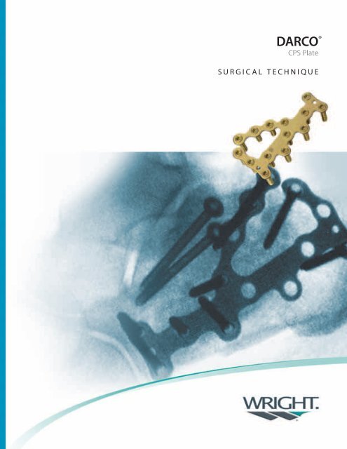
®DARCO<strong>CPS</strong> <strong>Plate</strong><strong>SURGICAL</strong> <strong>TECHNIQUE</strong>
PreoperativePlanningchapter1Prior to surgical intervention, thorough evaluation using radiograph and CTimaging of the fracture pattern is needed to accurately plan this complicatedreduction. A healthy respect for the integrity and condition of the soft tissuesis also needed and typically will delay surgery for 10 to 14 days or more.The following items should be planned for in the operating room:» DARCO® MRS Plating System» CHARLOTTE 3.0 and 4.3mm Multi-Use Compression Screw set» PRO-DENSE Injectable Regenerative Graft» Complete set of K-wires and large diameter Steinmann or Shands pins» Powered handpiece with large-diameter wire driver and Jacobs chuck» Straight and curved osteotomes» Cobb periostial elevator» Intraoperative flouroscopy» Lamina spreader and/or wire-based distractorPatient PositioningPosition the patient in a lateral decubitus position with padding of theappropriate bony prominences. It is recommended the down foot is scissoredforward, and the operative foot positioned behind it and on top of several bulkyblankets or sheets. This will allow better visualization with intra-operative c-armwithout overlap from the other foot. Hemostasis may be accomplished with athigh tourniquet.4Chapter 1Preoperative Planning
SurgicalTechniquechapter2Surgical Approach and RetractionDraw an extensile lateral approach, local landmarks and the course of the suralnerve on the skin. Create a curved skin incision with vertical limb halfwaybetween the peroneal tendons and Achilles, and the horizontal limb parallelto the plantar surface of the foot. The sural nerve is protected in both theproximal and distal aspect of the incision. Bring the incision sharply to boneafter identification of the sural nerve. Raise the skin as a full-thickness flap ina subperiosteal plane; take care to protect and elevate the peroneal tendonswithin the flap. Direct visualization of the subtalar joint and the calcanealcuboid(CC) joint should now be possible. Care should be taken to delicatelyhandle the flap with a “no touch” technique. 0.062 K-wires may be placed tomaintain retraction of the flap while avoiding excessive tension. | FIGURE 1Figure 1Chapter 2Surgical Technique5
chapterChapter Surgical13Title ReconstructionAny synovitis or hematoma is carefully removed from within the subtalar joint;this will allow visualization of the intra-articular fractures of the posterior subtalarfacet. | FIGURE 2 Often, there is a ‘blow-out’ type fracture of the lateral wall of thecalcaneus. This portion of the lateral wall may be carefully removed and held onthe back table for later reimplantation.Decompress the depressed joint fragments to allow reduction of the posteriorfacet of the subtalar joint. Often a Cobb elevator is used to elevate thesefragments back up to match to opposing talar surface. Once the posterior facetis reduced, use 0.062 K-wires to provisionally fix the joint surface. Realignmentof the joint is confirmed with both lateral and calcaneal axial flouroscopic views.Drive a large Steinman pin axially from the posterior calcaneal tuberosity.| FIGURE 3 This pin may be used a joystick to aid in decompression andmanipulation of the tuberosity.Upon confirmation of posterior facet realignment, drive two 1.6 mm guidewiresfor the CHARLOTTE 4.3mm Multi-Use Compression Screw from posteriorlateral to anterior medial in a parallel fashion, just within the dense subchondralbone beneath the posterior facet. These wires target the stable sustentaculumfragment medially. Confirm correct length and placement of these wires withlateral and calcaneal axial views. Measure using the cannulated depth gauge,drill with the 3.0mm Cannulated Drill Bit, and insert the appropriate lengthscrews. The screws should be advanced in an alternating fashion, and care takento prevent toggling of the articular fragments. Flouroscopy is again performed toconfirm correct screw placement within the sustentaculum and reduction of thesubtalar joint.Figure 2 Figure 36Chapter 13Description Surgical Reconstructionof Section
Attention is now directed to the position of the heel tuberosity. Typically thishas been displaced superiorly, shortened, and/or rotated into varus. Lever theSteinman pin to manipulate the tuberosity back down and out of varus, thenadvance the pin provide temporary stabilization. Lateral and calcaneal axialviews are used to confirm that the plantar calcaneal cortex is realigned, and theheel is in a neutral position.If pre-operative CT scan indicated fracture extension into the anterior calcanealbody and/or calcaneal-cuboid (CC) joint, this is now addressed. Inspect the CCjoint, reduce as necessary, and provisionally fix with 0.062 K-wires. It is importantto ensure that the anterior body is reduced and not translated superiorly.Replace the lateral wall fragment. Select the appropriately sized DARCO® <strong>CPS</strong>plate depending on patient anatomy, using flouroscopy as a reference. The platemay be temporarily held in place with the 1.1mm K-wires from the set. The platetypically does not need to be pre-bent or contoured.There is typically a bone void in the cancellous bone from the impaction of theinjury. This void may be backfilled with PRO-DENSE Injectable RegenerativeGraft to provide a scaffold for new bone growth, and potentially allow soonerpost-operative weightbearing.The DARCO® MRS system permits the usage of both locking and non-lockingscrews in all plate holes. Bicortical fixation is generally not required with lockingscrews; however, it should always be used with non-locking screws. Non-lockingscrews may be used to lag the plate closer to the underlying bone. If necessary,the PRO-DENSE graft may be drilled through to accept screws.Chapter 32Surgical ReconstructionTechnique7
Thread the Locking Drill Guide (P/N DC4169) into a central screw hole that issitting flush to bone. Use the 2.5mm Drill (P/N DC5136) through the locking drillguide. | FIGURE 4 Remove the drill guide and use the Depth Gage (P/N DC4263-2)to determine the appropriate screw length. | FIGURE 5Figure 4Figure 5Insert the screw into the pre-drilled hole and drive until flush with the plate.Repeat Part No. the steps described Description above to prepare Placement more screw in Trays locations. As yousecure the plate centrally and move distal toward the CC joint, use a bone hookwhile BOW Opening anchoring Wedge the plate <strong>Plate</strong> to for prevent Bunionssuperior displacement of the anteriorcalcaneal DC 2832-000 body. 0mm no spacer0 3 4DC 2832-003 3mm spacerIn-situ DC 2832-004 contouring 4mm of the spacer plate is easily accomplished 5 6 by threading 7 the LockingDC 2832-005 5mm spacerDrill Guide into a screw hole and using it as a bender. In this manner, the plateDC 2832-006 6mm spacermay DC 2832-007 be anatomically 7mm contoured spacer while protecting the locking threads in the plate.C-arm is again used to confirm restoration of anatomic alignment and position ofthe hardware. | FIGURE 6 Remove the provisional k-wires after final fixation of thefracture. UPS 2.7 General Purpose Plating SystemDC 2801-118 18mm18 20 22Wound DC 2801-120 Closure 20mmDC 2801-122 22mm24Deep DC 2801-124 periosteal tissue 24mmmay be closed with 0 absorbable suture. The subcutaneoustissue is closed with 2-0 absorbable sutures again using a “no-touch”technique. Sutures are initially placed at the periphery and gradually workedtowards MPJ Fusion the apex <strong>Plate</strong>of the flap. Skin is closed in an everted fashion.DC 2805-013 S: 28mm, 4 holes,2 compression slotsSDC 2805-015 M: 35mm, 6 holes2 compression slotsM LDC 2805-115 L: 45mm, 6 holes2 compression slotsFigure 68 Chapter 13Description Surgical Reconstructionof Section
Headline Ordering InformationHeadlineAppendixKit ListPart No. Description QuantityDMRSKITADMRSKIT1Implant KitInstrument KitLocked ScrewsDC 2820-014 14mm x 3.5mm 5DC 2820-016 16mm x 3.5mm 5DC 2820-018 18mm x 3.5mm 5DC 2820-020 20mm x 3.5mm 5DC 2820-022 22mm x 3.5mm 5DC 2820-024 24mm x 3.5mm 5DC 2820-026 26mm x 3.5mm 5DC 2820-028 28mm x 3.5mm 5DC 2820-030 30mm x 3.5mm 5DC 2820-035 35mm x 3.5mm 5DC 2820-040 40mm x 3.5mm 5Non-Locked ScrewsDC 2820-114 14mm x 3.5mm 2DC 2820-116 16mm x 3.5mm 2DC 2820-118 18mm x 3.5mm 2DC 2820-120 20mm x 3.5mm 2DC 2820-122 22mm x 3.5mm 2DC 2820-124 24mm x 3.5mm 2DC 2820-126 26mm x 3.5mm 2DC 2820-128 28mm x 3.5mm 2DC 2820-130 30mm x 3.5mm 2DC 2820-135 35mm x 3.5mm 2DC 2820-140 40mm x 3.5mm 2Instruments and accessoriesDC 35 Box System tray assembly 1DC 70-481 Bending forceps 1DC 4157 Bending iron 1DC 4169 Drill guide 2DC 4263-2 Depth gauge 1DC 4197 Forceps 1DC 4261Screwdriver, hexagonal,cannulated 1DC 5136 Drill bit, 2.5mm 2DC 5620 Cannulated drill bit 2.5mm 1NO 2228-012 K-wire 140 × 1.1mm 6DC 4584Screw holding andbending iron 1DARCO DARCO® <strong>CPS</strong> BOW <strong>Plate</strong> <strong>Plate</strong>9
Additional ProductsFor Bone Grafting, UsePRO-DENSEInjectable Regenerative Graft87SR-0410 10ccWright Medical Technology, Inc.5677 Airline RoadArlington, TN 38002901.867.9971 phone800.238.7188 toll-freewww.wmt.comWright Medical Europe SARue Pasteur BP 22283089 Toulon Cedex 9France011.33.49.408.7788 phonewww.wmt-emea.comTrademarks and ®Registered marks of Wright Medical Technology, Inc.DARCO® is a registered trademark of Wright Medical Technology, Inc.Patents pending.©2007 Wright Medical Technology, Inc. All Rights Reserved. SO 279-807