Aisin AW Co., Ltd. - ECCJ
Aisin AW Co., Ltd. - ECCJ
Aisin AW Co., Ltd. - ECCJ

Create successful ePaper yourself
Turn your PDF publications into a flip-book with our unique Google optimized e-Paper software.
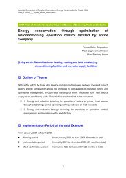
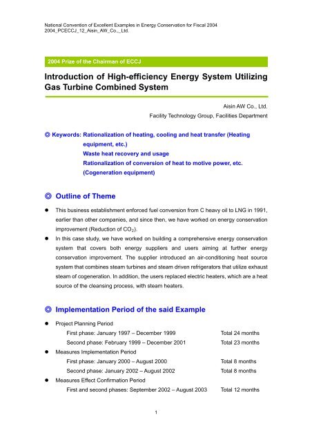
National <strong>Co</strong>nvention of Excellent Examples in Energy <strong>Co</strong>nservation for Fiscal 20042004_PC<strong>ECCJ</strong>_12_<strong>Aisin</strong>_<strong>AW</strong>_<strong>Co</strong>.,_<strong>Ltd</strong>.2004 Prize of the Chairman of <strong>ECCJ</strong>Introduction of High-efficiency Energy System UtilizingGas Turbine <strong>Co</strong>mbined System<strong>Aisin</strong> <strong>AW</strong> <strong>Co</strong>., <strong>Ltd</strong>.Facility Technology Group, Facilities Department◎ Keywords: Rationalization of heating, cooling and heat transfer (Heatingequipment, etc.)Waste heat recovery and usageRationalization of conversion of heat to motive power, etc.(<strong>Co</strong>generation equipment)◎ Outline of Theme• This business establishment enforced fuel conversion from C heavy oil to LNG in 1991,earlier than other companies, and since then, we have worked on energy conservationimprovement (Reduction of CO 2 ).• In this case study, we have worked on building a comprehensive energy conservationsystem that covers both energy suppliers and users aiming at further energyconservation improvement. The supplier introduced an air-conditioning heat sourcesystem that combines steam turbines and steam driven refrigerators that utilize exhauststeam of cogeneration. In addition, the users replaced electric heaters, which are a heatsource of the cleansing process, with steam heaters.◎ Implementation Period of the said Example• Project Planning PeriodFirst phase: January 1997 – December 1999Second phase: February 1999 – December 2001• Measures Implementation PeriodFirst phase: January 2000 – August 2000Second phase: January 2002 – August 2002• Measures Effect <strong>Co</strong>nfirmation PeriodFirst and second phases: September 2002 – August 2003Total 24 monthsTotal 23 monthsTotal 8 monthsTotal 8 monthsTotal 12 months1
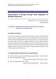
National <strong>Co</strong>nvention of Excellent Examples in Energy <strong>Co</strong>nservation for Fiscal 20042004_PC<strong>ECCJ</strong>_12_<strong>Aisin</strong>_<strong>AW</strong>_<strong>Co</strong>.,_<strong>Ltd</strong>.◎ Outline of Business Establishment• Detail of Business Manufacturing of automatic transmissions• No. of Employees 5,086 (As of April, 2003)• Annual Energy Usage AmountElectricity: 159,378 MWhLNG: 25,031,000 Nm 3◎ Outline of Target FacilitiesSupplier Side(Power Plants and Engines Room)User Side(Facility)GasTurbineGeneratorEfficient Operation by Utilizing ITElectricityExtracted SteamSteamHeaterFuel(NLG)ExhaustHeatBoilerGasTurbineGeneratorExtraction<strong>Co</strong>ndensingSteam TurbineGenerator<strong>Co</strong>ndenserSteamdrivenChillerSteamdrivenChillerSteamChilledWater for Air<strong>Co</strong>nditioningSteamHeaterHeating forCleansingProcessExhaustHeatBoilerHeatExchangerHot Waterfor Air<strong>Co</strong>nditioningDrain Recovery1. Reasons for Theme SelectionIt is expected that CO 2 emission increases with our production increases. Under thesecircumstances, companies have social responsibilities to enforce countermeasures againstglobal warming, and reduction of CO 2 emission is essential.We have set mid- and long-term energy strategies to promote energy conservationsystematically. Especially, introduction of a co-generation system is an important item forreduction of CO 2 emission. This case study is an example of high efficiency system basedon maximum utilization of exhaust heat.2
National <strong>Co</strong>nvention of Excellent Examples in Energy <strong>Co</strong>nservation for Fiscal 20042004_PC<strong>ECCJ</strong>_12_<strong>Aisin</strong>_<strong>AW</strong>_<strong>Co</strong>.,_<strong>Ltd</strong>.(1000 ton-c)Challenge Target:▲5% compared to '90(Reduction of20,000 tons)(Fiscal Year)2. Understanding of Current Situation(1) Energy Environment that Surrounds Our <strong>Co</strong>mpany[Tougher Environmental Regulations]• Act concerning the Rational Use of Energy (Energy <strong>Co</strong>nservation Act)- Obligation to reduce energy intensity by 1% compared to theprevious fiscal year- On-site inspection of energy management situation by thegovernment• Nippon Keidanren, Japan Automobile Manufacturers Association, Inc.(All Toyota consolidated environmental management)- Reduction of CO 2 emission by 10% by 2010 compared to 1990 in the long termand by 5% by 2005 in the midterm.[<strong>Co</strong>ncerns about deterioration of energy cost]• Introduction of environmental tax- Full-scale debate on introduction of environmental tax* Energy conservation isessential. Discovery ofenergy conservationitems andimplementationaccording to mid- andlong-term scenario arerequired.3
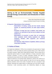
National <strong>Co</strong>nvention of Excellent Examples in Energy <strong>Co</strong>nservation for Fiscal 20042004_PC<strong>ECCJ</strong>_12_<strong>Aisin</strong>_<strong>AW</strong>_<strong>Co</strong>.,_<strong>Ltd</strong>.(2) Our Energy <strong>Co</strong>nservation ScenarioTransmission ofInformation for "DigitalManufacturing"<strong>Co</strong>nsidering LCACO 2Reduction(1,000 tons)<strong>Co</strong>ntinuous Improvementby Energy SubcommitteeDiscovery of New ItemsEnhancement of ResearchSystem- Group <strong>Co</strong>mpanies andManufacturesHeadquarter Factory (Thisfactory) Second PhaseHeadquarter Factory (This factory) First PhaseOkazaki Factory (introduced in 1998)Energy <strong>Co</strong>nservationActivities in ExistingManufacturing LinesCreating Energy<strong>Co</strong>nservation ProcessesThis CaseStudyImprovement ofEfficiency by<strong>Co</strong>generationFiscalYearFig. 3 shows our energy conservation scenario to achieve the target of CO 2 reduction by2005. To reduce CO 2 , we think there are three general areas: improvement on the supplierside, improvement on the user side, and discovery of new items for further improvement.Among these, we have introduced a cogeneration system to Okazaki Factory in 1998 withgreat success. Introduction of a cogeneration system with higher efficiency to theheadquarter Factory is considered to be essential. Based on the timing of facilityreplacement on the supplier side and improvement of facilities on the user side, weintroduce the system in 2000 and 2002 in a phased manner.3. Progress of Activities(1) Implementation StructureIn introducing the system, we considered that maximum utilization of exhaust heat andcontrol of investment cost are important points. The supplier side promoted introduction ofnew technologies working together with manufacturers with a view to utilize the nationalsubsidy system, while the user side (factory) promoted effective utilization of exhaust steamthrough our energy subcommittee.4
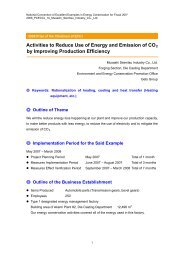
National <strong>Co</strong>nvention of Excellent Examples in Energy <strong>Co</strong>nservation for Fiscal 20042004_PC<strong>ECCJ</strong>_12_<strong>Aisin</strong>_<strong>AW</strong>_<strong>Co</strong>.,_<strong>Ltd</strong>.(2) Target Settings (the second introduction phase)• Reduction of energy cost: 280 million yen/year or more(Payout period: within 5 years)• Reduction of CO 2 emission: 5,000 ton/year or more(25% of the company-wide target)<strong>Co</strong>stSustainabilityPursuit of "BEST Energy" for Stable Supply of Cheap andClean Energy(3) Problems and their Study1) Investigation on the most appropriate capacity of the cogeneration systemWe investigated the power machine, which is the core of the cogeneration system, and itsmost appropriate capacity.1) Investigation of Engines and Turbines for <strong>Co</strong>generation2) Investigation of Most Appropriate Capacity of Gas TurbinePerformanceInvestmentMaintainabilityEnvironmentDieselEngineGasEngineGasTurbine1,000 Ton/YearMostAppropriateCapacityCO 2ReductionMonetaryAmount ofEffect100 MillionYen/YearMonetary Amount of EffectSmallGas Turbine CapacityLargeFocusing on cost and environment, gas turbine that iseffective for both is adopted.Adopt gas turbines of 14,000 kW-class that is mosteffective for our company. => <strong>Co</strong>st and improvement ofsystem efficiency are the challenge.5
National <strong>Co</strong>nvention of Excellent Examples in Energy <strong>Co</strong>nservation for Fiscal 20042004_PC<strong>ECCJ</strong>_12_<strong>Aisin</strong>_<strong>AW</strong>_<strong>Co</strong>.,_<strong>Ltd</strong>.(2) Investigation to Improve the Efficiency of the <strong>Co</strong>generation SystemImprovement ofSteam <strong>Co</strong>llectionInvestigation of Most AppropriateOperation PatternVariableExtractionPressure(Case Study 1)Introduction ofSteam TurbinesUtilization ofIT (CaseStudy 3)Improvement of PowerGeneration EfficiencyImprovement of<strong>Co</strong>mpressorsImprovement ofBurners. ReplacingHeat Sources ofAir <strong>Co</strong>nditioningwith SteamImprovement onthe User SideRecovery of<strong>Co</strong>ndensingHeat (CaseStudy 2)Using SteamHeaters (CaseStudy 4)Improvement of Heat Efficiency(Utilization of Exhaust Heat)Higher <strong>Co</strong>mbustion TemperatureSuction air<strong>Co</strong>olingHeatingSupply WaterDrain<strong>Co</strong>llectionImprovement ofRadiation Loss・・・Adopted in This Case StudyImprovement of<strong>Co</strong>generationSystemEfficiencyDrain <strong>Co</strong>llectionImprovement ofHeat Exchanger4. Details of Measures(1) Case Study 1 (New Technology 1): <strong>Co</strong>ntrol of optimum load of electricgenerators and chiller by introducing variable extraction pressure ofthe steam turbines (patent application)The pressure of the exhaust steam was 1.8 MPa, whereas the pressure required on the userside facility (steam driven chiller and production facility) was 0.6 MPa - 0.8 MPa. Toeffectively use this pressure difference, extraction condensing steam turbine electricgenerators were introduced. In addition, for further improvement of efficiency, we focused onfluctuation of the pressure required by the steam absorption type chiller and control theextraction pressure according to the load so that the maximum electricity is alwaysgenerated.6
National <strong>Co</strong>nvention of Excellent Examples in Energy <strong>Co</strong>nservation for Fiscal 20042004_PC<strong>ECCJ</strong>_12_<strong>Aisin</strong>_<strong>AW</strong>_<strong>Co</strong>.,_<strong>Ltd</strong>.Exhaust SteamIncrease by 164 kWExtraction<strong>Co</strong>ndensing SteamTurbine GeneratorGenerated Electricity Output: Normally 805 kW => 969Extraction Pressure <strong>Co</strong>ntrolValveElectricityExtraction Steam:Normally 0.8 MPa =>Variable Range of 0.6 -0.8 MPaFlow Rate <strong>Co</strong>ntrol Valve<strong>Co</strong>llected DrainChilledWater for Air<strong>Co</strong>nditioning<strong>Co</strong>olingTowerSteam Absorption type Chiller(Replaced from Gas to Steam)Steam forManufacturing (HeatSource for CleansingMachine)The pressure of the extracted steam of the absorption type chiller was controlled high usingthe extraction pressure control valve when the cooling load is high and when the load is lowor the temperature of the cooling water is low, it was controlled low so that the generatedelectricity is the maximum. (Fig.7)As shown in Fig. 8, for example, when the chiller load is 80%, extraction pressure wastraditionally 0.8 MPa, but it was lowered to 0.6 MPa, and we succeeded to increase theoutput electricity of steam turbines by 164 kW.Example: When the Chiller Load is 80%ElectricityOutputGeneratedby SteamTurbineImproved<strong>Co</strong>ntrolTraditional<strong>Co</strong>ntrolExtraction PressureEffect of Introduction 1 (Gas Turbine + Steam Turbine + Variable Extraction Pressure)Reduction of Energy <strong>Co</strong>st: 190 Million Yen/Year, Reduction of CO 2 emission: 3,600 ton/Year7
National <strong>Co</strong>nvention of Excellent Examples in Energy <strong>Co</strong>nservation for Fiscal 20042004_PC<strong>ECCJ</strong>_12_<strong>Aisin</strong>_<strong>AW</strong>_<strong>Co</strong>.,_<strong>Ltd</strong>.(2) Case Study 2 (New Technology 2): Optimum control of temperature ofthe steam condenser cooling water (patent application)Traditionally, hot water for air conditioning was generated by heat exchanger using steam. Inthis system, the temperature of the steam condenser cooling water was controlled accordingto the heating load so that it can be used for air conditioning. This eliminates extractedsteam for heating and increases generated electricity. In seasons when heating load is lowor none, we adopted the operation that the temperature of the steam condenser coolingwater was controlled lower and vacuum of the steam condenser was raised.Extraction<strong>Co</strong>ndensing SteamTurbine GeneratorExhaust Steam (24t)DrainRecoverySteam<strong>Co</strong>ndenserSteam<strong>Co</strong>ndenser<strong>Co</strong>oling WaterGenerated Electricity Output: Increase by 1,300 kW= 1,000 kW (<strong>Co</strong>llection of Hot Water for Heating) +300 kW (<strong>Co</strong>ntrol of Most Appropriate Temperature)HeatExchanger forHeat ReleaseTemperature SensorElectricity<strong>Co</strong>ntrol Temperature of Steam<strong>Co</strong>ndenser <strong>Co</strong>oling Wateraccording to Heating LoadInverter<strong>Co</strong>olingTowerHot Water forAir<strong>Co</strong>nditioningSteam forManufacturingAs shown in Fig. 9, the temperature of the steam condenser cooling water of was controlledaccording to operation in each season. In winter, the temperature of the cooling water wasraised so that it can be used as hot water for air conditioning. In other seasons, thetemperature of the cooling water was lowered to increase vacuum of the steam condenserso that more electricity can be generated.For example, as shown in Fig. 10, by lowering the temperature of the steam condensercooling water from 42℃ to 35℃, vacuum of the steam condenser was increased and 300kW of electricity was more generated.8
National <strong>Co</strong>nvention of Excellent Examples in Energy <strong>Co</strong>nservation for Fiscal 20042004_PC<strong>ECCJ</strong>_12_<strong>Aisin</strong>_<strong>AW</strong>_<strong>Co</strong>.,_<strong>Ltd</strong>.Example: Generated Electricity Output inInterim Seasons and WinterInterim SeasonsWinterTemperature of Steam <strong>Co</strong>ndenser <strong>Co</strong>oling WaterEffect of Introduction 2 (<strong>Co</strong>llection of Hot Water for Heating + <strong>Co</strong>ntrol ofMost Appropriate Temperature)Reduction of Energy <strong>Co</strong>st: 54 Million Yen/Year, Reduction of CO 2 Emission: 980 ton/Year(3) Case Study 3 (New Technology 3): Optimum operation by utilizing ITSystems that use heat exchangers such as chillers are affected by external factors, so theminimum point of operation cost is not constant. Even when each facility is affected by theweather, deterioration of facility, and load conditions etc., to realize a system that candetermine the optimum operational condition at the moment based on the actual operationdata (pressure, temperature, act.) and to provide optimum demand and supply operation asdescribed above (New technologies 1 and 2)., we introduced memory-based reasoning(MBR) method.9
National <strong>Co</strong>nvention of Excellent Examples in Energy <strong>Co</strong>nservation for Fiscal 20042004_PC<strong>ECCJ</strong>_12_<strong>Aisin</strong>_<strong>AW</strong>_<strong>Co</strong>.,_<strong>Ltd</strong>.Fuel (LNG)Central MonitoringDeviceMBR DeviceNo2. GT <strong>Co</strong>generator7210kWElectricityNo1. GT <strong>Co</strong>generator7210kWExtraction <strong>Co</strong>ndensingTurbineElectricityGeneratorSteamTemperatureDetectorExtracted Steam(0.6MP – 0.8MPSteam ExtractionPressure <strong>Co</strong>ntrol ValveSteam<strong>Co</strong>ndenserHeat Exchanger<strong>Co</strong>oling TowerTo the SupplyWater TankFlow Rate<strong>Co</strong>ntrolTo Existing Absorptiontype ChillersPressure and Flow Rate Detector<strong>Co</strong>olingWaterTemperatureDetectorSteam Absorptiontype ChillerTemperature DetectorTurbo type ChillerTemperatureDetectorChilled/HotWater for Air<strong>Co</strong>nditioningFig. 12 shows an example of controlling using MBR unit, considering deterioration of thesteam absorption type chiller. Even when the cooling load is the same, required extractedsteam pressure (required pressure) may be different due to deterioration of the chiller, andextraction pressure that fits the deterioration is required.By introducing MBR unit to determine optimum extraction pressure according to the currentpredicted characteristics of the chiller obtained from the actual data, we succeeded toprevent excess operation of turbo (electric) chiller whose total efficiency is poor and predictthe true values at earliest for efficient control. (Steam absorption type chillers are givenpriority for operation)10
National <strong>Co</strong>nvention of Excellent Examples in Energy <strong>Co</strong>nservation for Fiscal 20042004_PC<strong>ECCJ</strong>_12_<strong>Aisin</strong>_<strong>AW</strong>_<strong>Co</strong>.,_<strong>Ltd</strong>.MBR DeviceInputExample of <strong>Co</strong>ntrol: <strong>Co</strong>ntrolling Extraction Pressure<strong>Co</strong>nsidering Deterioration of Steam Absorption Type ChillerOutputPressureDataTwo YearsAgoLast YearCurrent PredictedCharacteristicsDirection of ExtractionPressureTemperatureDataFlow RateDataMost AppropriateExtraction Pressure PointExtraction Pressure (MPa)Effect of IntroductionIncluded in Case Studies 1 and 2(4) Case Study 4: Using steam for heat source of the cleanser inmanufacturing lineWe replaced electric heaters that are used as heat source for cleansing process of themanufacturing lines with steam heaters to improve utilization according to TPO (time, placeand occasion). In addition, to prevent deterioration of work environment due to use of steamfor heating, all steam drain is recovered and used for heating supply water of exhaust heatboilers.1) Facilities that can be replaced with steam in our companyFacility Technology <strong>Co</strong>st EffectHeat Sourcefor Air<strong>Co</strong>nditioning○ ○ ○CleansingMachine○ ○ ○Oil InjectionSystem○ ○ △Heat source for air conditioning and cleansing machinesthat are effective in technology, cost, and effect(However, two heat sources for air conditioning areadopted on the premise that their lives are updated.)11
National <strong>Co</strong>nvention of Excellent Examples in Energy <strong>Co</strong>nservation for Fiscal 20042004_PC<strong>ECCJ</strong>_12_<strong>Aisin</strong>_<strong>AW</strong>_<strong>Co</strong>.,_<strong>Ltd</strong>.(2) Summery of Effects[ Reduction of Energy <strong>Co</strong>st ]Million Yen/Yearton/Year[ Reduction of CO 2 Emission ]TargetActualPerformanceTargetActualPerformancePayout PeriodTarget: within 5 Years => Actual: 4.7 Years(Utilizing National Subsidy System)6. SummaryIn this case study, we have built a high efficiency energy system that covers both energysupplier side and user side introducing four new technologies to utilize exhaust heat atmaximum. As a result, we have reduced investment by utilizing the national subsidy systemand achieved the target for CO 2 reduction, so we significantly contributed to prevention ofglobal warming.7. Future PlansWe plan to continuously evaluate facilities that are introduced in this case study and aimfurther improvement of efficiency. We also plan to investigate optimum parameters based onthe memory-based reasoning method utilizing IT, and investigate and implement horizontalspread to other engines and turbines including other plants. In addition, to achieve thecompany-wide target of CO 2 reduction, we would like to involve entire company to discoverand enforce new specific items and become the top runner of energy management alwaysassuming the best energy management.13