ibm.com /p c/us/eserver/xseries/lib rary - IBM Quicklinks
ibm.com /p c/us/eserver/xseries/lib rary - IBM Quicklinks
ibm.com /p c/us/eserver/xseries/lib rary - IBM Quicklinks
- No tags were found...

Create successful ePaper yourself
Turn your PDF publications into a flip-book with our unique Google optimized e-Paper software.
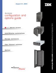
May 13, 2003United Statesconfiguration andoptions guidexSeries serversIntelliStation workstationsStorage enclosuresFibre Channel solutionsOptions<strong>ibm</strong>.<strong>com</strong>/pc/<strong>us</strong>/<strong>eserver</strong>/<strong>xseries</strong>/<strong>lib</strong><strong>rary</strong>
Introducing in this issue ...xSeries 450 (IA-64) with 1GHz Itanium2 processorUSB Conversion OptionxSeries 345 model with 3.06GHz XeonprocessorxSeries 305 models with 2.8GHzPentium 4 processorxSeries 235 models with 3.06GHzXeon processorLTO FH Generation-2 Tape DriveOptionFirmware for Fibre Channel switchesNOS Preload section
Table of ContentsInformation Sources ..................................................2Server Product Positioning ........................................4xSeries Selection Guide.........................................6BladeCenter .......................................................147xSeries DC Power and NEBS-<strong>com</strong>pliant Models...156External Storage Expansion Unit Overview ...........157Table of ContentsxSeries Network Operating System Preloads ...........9Fibre Channel Solutions Overview.........................161IntelliStation® Video Adapter Selection Guide........11Rack Cabinets and Options...................................183IntelliStation E Pro 6216...........................................12Rack Console Options ...........................................189IntelliStation E Pro 6226...........................................16xSeries Rack Power Configurator..........................194IntelliStation M Pro 6219..........................................21Appendix A: Tape Drive Attributes ........................203IntelliStation Z Pro 6221...........................................28Appendix B: Tape Lib<strong>rary</strong> Attributes .....................205xSeries 205..............................................................35Appendix C: UPS Runtime Estimate (minutes)......206xSeries 225..............................................................44xSeries 235..............................................................55xSeries 255..............................................................66xSeries 305..............................................................78xSeries 335..............................................................86xSeries 343 (NEBS-<strong>com</strong>pliant) ................................94xSeries 345..............................................................97Appendix D: SCSI Cables -Storage Units - Controllers.....................................211Appendix E: Serial I/O ...........................................212Appendix F: Internal Cabling Overview.................213Appendix G: System Management Overview........215Appendix H: xSeries I/O Option Attributes ............224Important Notes .....................................................226xSeries 360............................................................106xSeries 440............................................................114xSeries 450............................................................126RXE-100 Remote Expansion Enclosure ................134VMware ESX Server 1.5.........................................138Datacenter Solution Program ................................1391
Information SourcesEurope, Middle East and Africa (EMEA)Audience Where to go How to get<strong>IBM</strong> xSeries Configuration and Options Guide, Rack Configurator, Configuration AidB<strong>us</strong>iness Partnersand <strong>IBM</strong> Employeeswww.pc.<strong>ibm</strong>.<strong>com</strong>/europe/configuratorsDownload or register for E-mail distributionFeedback psg_configure@uk.<strong>ibm</strong>.<strong>com</strong> E-mailCanada<strong>IBM</strong> xSeries Configuration and Options GuideC<strong>us</strong>tomers www.pc.<strong>ibm</strong>.<strong>com</strong>/ca/<strong>eserver</strong>/<strong>xseries</strong>/index.shtml Select Support then Configuration and Options Guide.B<strong>us</strong>iness Partners www.pc.<strong>ibm</strong>.<strong>com</strong>/partner/ca Select Marketing Essentials then Configurators (<strong>us</strong>er ID and password required).<strong>IBM</strong> Employees Marketing Essentials Main menu --> ConfiguratorsFeedback www.pc.<strong>ibm</strong>.<strong>com</strong>/partner/ca/feedback.html -<strong>IBM</strong> xSeries and Netfinity Rack ConfiguratorC<strong>us</strong>tomers www.pc.<strong>ibm</strong>.<strong>com</strong>/<strong>us</strong>/<strong>eserver</strong>/<strong>xseries</strong>/<strong>lib</strong><strong>rary</strong>/configtools.html Select Support then Rack Configurator.B<strong>us</strong>iness Partners www.pc.<strong>ibm</strong>.<strong>com</strong>/partner/ca Select Marketing Essentials then Configurators (<strong>us</strong>er ID and password required).<strong>IBM</strong> Employees Marketing Essentials Main menu --> ConfiguratorsFeedback <strong>ibm</strong>_netfinity_rack_configurator@vnet.<strong>ibm</strong>.<strong>com</strong> E-mailLatest Product & Technical InformationC<strong>us</strong>tomers www.pc.<strong>ibm</strong>.<strong>com</strong>/ca/<strong>eserver</strong>/<strong>xseries</strong>/index.shtml -B<strong>us</strong>iness Partners www.pc.<strong>ibm</strong>.<strong>com</strong>/partner/ca or call the PSMT User ID and Password required.<strong>IBM</strong> Employees Marketing Essentials From main menu or by brand category.Latin America<strong>IBM</strong> xSeries Configuration and Options GuideC<strong>us</strong>tomers www.pc.<strong>ibm</strong>.<strong>com</strong>/<strong>us</strong>/<strong>eserver</strong>/<strong>xseries</strong>/<strong>lib</strong><strong>rary</strong>/configtools.html Select Support then Configuration and Options Guide.B<strong>us</strong>iness Partners Marketing Essentials in ePartner User ID and Password required. 1<strong>IBM</strong> Employees Marketing Essentials in Lot<strong>us</strong> Notes PartnerInfo From main menu or by brand category.Feedback laconfig@<strong>us</strong>.<strong>ibm</strong>.<strong>com</strong> E-mail<strong>IBM</strong> xSeries and Netfinity Rack ConfiguratorC<strong>us</strong>tomers www.pc.<strong>ibm</strong>.<strong>com</strong>/<strong>us</strong>/<strong>eserver</strong>/<strong>xseries</strong>/<strong>lib</strong><strong>rary</strong> Select Support then Rack ConfiguratorB<strong>us</strong>iness Partners Marketing Essentials in ePartner User ID and Password required. 1<strong>IBM</strong> Employees Marketing Essentials in PartnerInfo From main menu or by brand category.Feedback <strong>ibm</strong>_netfinity_rack_configurator@vnet.<strong>ibm</strong>.<strong>com</strong> E-mailLatest Product & Technical InformationC<strong>us</strong>tomers www.pc.<strong>ibm</strong>.<strong>com</strong>/la -B<strong>us</strong>iness Partners www.pc.<strong>ibm</strong>.<strong>com</strong>/la/ or www.pc.<strong>ibm</strong>.<strong>com</strong>/br User ID and Password required. 1<strong>IBM</strong> Employees Marketing Essentials in PartnerInfo -1. To request a <strong>us</strong>er ID and password, go to www.pc.<strong>ibm</strong>.<strong>com</strong>/la. Select PC PartnerInfo, then select country. On the country page, select the link for PartnerInfo <strong>us</strong>er ID and passwordrequests.The information contained in this document has not been submitted to any formal <strong>IBM</strong> test. The following paragraph does not apply to the United Kingdom or any country where anysuch provisions are inconsistent with local law:The <strong>us</strong>e of this information or the implementation of any of these techniques is a c<strong>us</strong>tomer responsibility and depends on the c<strong>us</strong>tomer’s ability to evaluate and integrate them into thec<strong>us</strong>tomer’s operational environment. While each item may have been reviewed by <strong>IBM</strong> for accuracy in a specific situation, there is no guarantee that the same or similar results will beobtained elsewhere. C<strong>us</strong>tomers attempting to adapt these techniques to their own environments do so at their own risk.The following sample configurations are for ill<strong>us</strong>tration only and may not be suitable for any specific c<strong>us</strong>tomer installation. Contact your <strong>IBM</strong> B<strong>us</strong>iness Partner or <strong>IBM</strong> MarketingRepresentative for assistance with your specific configuration requirements.2
United StatesAudience Where to go How to get<strong>IBM</strong> xSeries Configuration and Options Guidewww.pc.<strong>ibm</strong>.<strong>com</strong>/<strong>us</strong>/<strong>eserver</strong>/<strong>xseries</strong>/<strong>lib</strong><strong>rary</strong>/configtools.html Select Configuration and Options Guide.C<strong>us</strong>tomerswww.pc.<strong>ibm</strong>.<strong>com</strong>/<strong>us</strong>/<strong>com</strong>patSelect Configuration and Options Guide.B<strong>us</strong>iness Partners www.pc.<strong>ibm</strong>.<strong>com</strong>/partner/<strong>us</strong>/ User ID and Password required.<strong>IBM</strong> EmployeesPC Marketing Essentials (US) on Lot<strong>us</strong> Notes databaseD03DB035\p_dir\pcpartnr\marketng\me4fe-<strong>us</strong>.nsfMain menu --> Configuration and Options Guid<strong>eserver</strong>proven.raleigh.<strong>ibm</strong>.<strong>com</strong>/cog/index.shtmlinternal siteFeedback mipdata@<strong>us</strong>.<strong>ibm</strong>.<strong>com</strong> E-mail<strong>IBM</strong> xSeries and Netfinity Rack ConfiguratorC<strong>us</strong>tomers www.pc.<strong>ibm</strong>.<strong>com</strong>/<strong>us</strong>/<strong>eserver</strong>/<strong>xseries</strong>/<strong>lib</strong><strong>rary</strong>/configtools.html Select Configuration Tools.B<strong>us</strong>iness Partnerswww.pc.<strong>ibm</strong>.<strong>com</strong>/partner/<strong>us</strong>/Select Sales Tools, then Marketing Essentials, then <strong>IBM</strong> PC Server--> Rack Configurator.User ID and password required.<strong>IBM</strong> EmployeesPC Marketing Essentials (US) on Lot<strong>us</strong> Notes databaseD03DB035\p_dir\pcpartnr\marketng\me4fe-<strong>us</strong>.nsfMain menu --> ConfiguratorsFeedback <strong>ibm</strong>_netfinity_rack_configurator@vnet.<strong>ibm</strong>.<strong>com</strong> E-mail<strong>IBM</strong> xSeries Configuration Aidwww.pc.<strong>ibm</strong>.<strong>com</strong>/qtechinfo/MIGR-41411.htmlC<strong>us</strong>tomers, B<strong>us</strong>iness Partners,<strong>IBM</strong> Employeeswww.pc.<strong>ibm</strong>.<strong>com</strong>/<strong>us</strong>/<strong>eserver</strong>/<strong>xseries</strong>/<strong>lib</strong><strong>rary</strong>/configtools.htmlFeedback psg_configure@uk.<strong>ibm</strong>.<strong>com</strong> E-mailPC Sales Guide/Configurator and WorkPad Pricer (updated twice per week)B<strong>us</strong>iness Partnerspsg.partner.boulder.<strong>ibm</strong>.<strong>com</strong>/partner/fpages.nsf/HTML/United+States.PSGC/$FILE/pcconfig.htmlUser ID and password required.<strong>IBM</strong> Employeesw3-1.<strong>ibm</strong>.<strong>com</strong>/psg/essentials/<strong>us</strong>/me4fe-<strong>us</strong>.nsf/$$FrameSet?ReadFormSelect Configurators.Feedback BMSHD08@<strong>us</strong>.<strong>ibm</strong>.<strong>com</strong> E-mailLatest Product & Technical InformationC<strong>us</strong>tomerswww.pc.<strong>ibm</strong>.<strong>com</strong>/<strong>us</strong>/<strong>eserver</strong>/<strong>xseries</strong>or call 1-800-772-2227B<strong>us</strong>iness Partners www.pc.<strong>ibm</strong>.<strong>com</strong>/partner/<strong>us</strong>/ or call 1-800-426-7763 Select Products & Services (<strong>us</strong>er ID and password required).<strong>IBM</strong> EmployeesPC Marketing Essentials (US) on Lot<strong>us</strong> Notes databaseD03DB035\p_dir\pcpartnr\marketng\me4fe-<strong>us</strong>.nsfAdditional URLsFrom main menu or by brand category.Information SourcesAudience Where to go How to getTechnical spec sheets (PSREF) www.pc.<strong>ibm</strong>.<strong>com</strong>/<strong>us</strong>/<strong>eserver</strong>/<strong>xseries</strong>/<strong>lib</strong><strong>rary</strong>.html Select Technical spec sheets (PSREF).<strong>IBM</strong> Datacenter Solutionswww.pc.<strong>ibm</strong>.<strong>com</strong>/ww/<strong>eserver</strong>/<strong>xseries</strong>/windows/datacenter.htmlCl<strong>us</strong>tering (US, LA, CAN) www.pc.<strong>ibm</strong>.<strong>com</strong>/ww/<strong>eserver</strong>/<strong>xseries</strong>/cl<strong>us</strong>tering/index.html Select appropriate category or server.Benchmark Results www.pc.<strong>ibm</strong>.<strong>com</strong>/ww/<strong>eserver</strong>/<strong>xseries</strong>/benchmarks/ Select appropriate category or server.Options/NOS/ServerCompatibilitywww.pc.<strong>ibm</strong>.<strong>com</strong>/<strong>us</strong>/<strong>com</strong>patSelect appropriate Product Type.NOS - Hot-Plug/Failover Support www.pc.<strong>ibm</strong>.<strong>com</strong>/<strong>us</strong>/<strong>com</strong>pat Select Active PCI Info.<strong>IBM</strong> Storage Products www.storage.<strong>ibm</strong>.<strong>com</strong> Select appropriate category .Adobe ® Acrobat ® Reader v5.0 www.adobe.<strong>com</strong>/products/acrobat/readstep.html Follow instructions.Adv Sys Mgmt Adapter FirmwareFlash BIOS Updateswww.pc.<strong>ibm</strong>.<strong>com</strong>/ww/<strong>eserver</strong>/<strong>xseries</strong>www.pc.<strong>ibm</strong>.<strong>com</strong>/ww/<strong>eserver</strong>/<strong>xseries</strong>Select Servers, select Intel-based Servers, select Fixes, select Get Fixes, selectappropriate category.Select Servers, select Intel-based Servers, select Fixes, select Get Fixes, select devicedrivers by server, select appropriate category.ServeRAID Updateswww.pc.<strong>ibm</strong>.<strong>com</strong>/ww/<strong>eserver</strong>/<strong>xseries</strong>Select Servers, select Intel-based Servers, select Fixes, select Get Fixes, selectappropriate category.VMware www.pc.<strong>ibm</strong>.<strong>com</strong>/ww/<strong>eserver</strong>/<strong>xseries</strong>/vmware.html -Options Continuation Program www.pc.<strong>ibm</strong>.<strong>com</strong>/ww/ocp -INTERNATIONAL BUSINESS MACHINES CORPORATION PROVIDES THIS PUBLICATION “AS IS” WITHOUT WARRANTY OF ANY KIND, EITHEREXPRESSED OR IMPLIED, INCLUDING, BUT NOT LIMITED TO, THE IMPLIED WARRANTIES OF MERCHANTABILITY OR FITNESS FOR APARTICULAR PURPOSE. SOME STATES DO NOT ALLOW DISCLAIMER OF EXPRESS OR IMPLIED WARRANTIES IN CERTAIN TRANSACTIONS.THEREFORE, THIS STATEMENT MAY NOT APPLY TO YOU. THERE IS NO GUARANTEE THAT <strong>IBM</strong> WILL MARKET ANY PARTICULAR PRODUCTIN YOUR COUNTRYUpdated 05/13/03For the latest product & technical information, refer to the Information Sources on pages 2 & 3.3
Server Product PositioningWorkloadx450Increased Capacity:SMPStorageI/OAvailability Featuresx440x360x345x255BladeCenter HS20x335x235x225x305x205InfrastructureApplicationNumber of Clients4
When in a <strong>com</strong>petitive situation, this table suggests the appropriate <strong>IBM</strong> xSeries server to bid against other vendors’ equipment. However, as an <strong>IBM</strong> b<strong>us</strong>inesspartner, you may determine that c<strong>us</strong>tomer-specific requirements may make an alternative <strong>IBM</strong> solution a better choice.IA-64ValueUniversal/TowerDepartmental/MissionCriticalUniversal/TowerModularRack-optimized<strong>IBM</strong>: xSeries 450Dell: PowerEdge 7150HP: ProLiant rx5670Modular EnterpriseScalable NodesIA-32>4-way<strong>IBM</strong>: xSeries 440 (Xeon MP)4-way2-wayUni<strong>IBM</strong>: xSeries 225Dell: PowerEdge 1600SCHP: ProLiant ML350G3<strong>IBM</strong>: xSeries 205Dell: PowerEdge 500SCHP: ProLiant tc2100<strong>IBM</strong>: xSeries 255Dell: PowerEdge 6600HP:ProLiant ML570<strong>IBM</strong>: xSeries 235Dell: PowerEdge 2500HP:ProLiant ML370<strong>IBM</strong>: xSeries 360Dell: PowerEdge 6650HP: ProLiant DL580G2<strong>IBM</strong>: xSeries 335, xSeries 345Dell: PowerEdge 1650, 2650HP: ProLiant DL360G2, DL380<strong>IBM</strong>: xSeries 305Dell: PowerEdge 350HP: ProLiant DL320<strong>IBM</strong>: xSeries 440 (Xeon)Dell: PowerEdge 6650HP: ProLiant DL580G2<strong>IBM</strong>: BladeCenter HS20Product PositioningUpdated 05/13/03For the latest product & technical information, refer to the Information Sources on pages 2 & 3.5
xSeries Selection GuideThis graph represents general guidelines for selecting the appropriate server based on the number of <strong>us</strong>ers that can be supported in a particular application environment.This chart is for general guidance since each c<strong>us</strong>tomer environment is unique and is unlikely to be precisely represented by any of the specific applications in the chart,but by <strong>us</strong>ing the chart, a reasonable approximation can be derived. External Storage Units are utilized when internal capacities are exceeded. Utilize the chart by followingthe steps outlined at the end of this section. These are not published benchmark results. Access www.pc.<strong>ibm</strong>.<strong>com</strong>/ww/<strong>eserver</strong>/<strong>xseries</strong>/benchmarks/index.html to obtainthe benchmark data.Application/Expectation ofMaximum # of UsersDB Transaction ProcessingSelect, Update and Delete;Does not include image orDecision SupportxSeries2052.8GHz/533MHz-512KBPentium 4xSeries 2252.8GHz/533MHz-512KB DualXeonxSeries3052.67GHz/533MHz-512KBPentium 4xSeries 335Dual3.06GHz/533MHz-512KBXeonxSeries 3452.8GHz/533MHz-512KB DualXeonxSeries 2352.8GHz/533MHz-512KB DualXeon# Users 2290 8660 2750 6260 8660 8660# Processors 1 2 1 2 2 2Memory 2GB 8GB 2 - 4GB 4GB 8GB 8GB# Hard Disk Drives 20 to 30 50 to 70 40 to 50 70 to 90 50 to 70 50 to 70# RAID Adapters >2 or Fibre >2 Fibre Fibre >2 >2# Network Connections 1 1Gb 1Gb 1Gb 1Gb 1Gb# Users 1540 6050 1980 6160 6050 6050# Processors 1 2 1 2 2 2File and PrintMemory 2GB 3 - 4GB 2 - 3GB 3 - 4GB 3 - 4GB 3 - 4GBApplication is stored locally.(For server stored applications# Hard Disk Drives 10 to 20 50 to 90 14 to 25 50 to 90 50 to 90 50 to 90- cut number of <strong>us</strong>ers in half). # RAID Adapters 1 or Fibre >4 1 or Fibre 2 or Fibre >4 >4# 100Mbps EthernetConnections1Gb 1Gb 1Gb 1Gb 1Gb 1Gb# Users 1760 5060 2750 5060 5060 5060Lot<strong>us</strong>® Notes®10% Power Users 40% Mail50% Mail & DBMicrosoft® ExchangeServer 2000100% Med Users30MB MailboxSAP 3-Tier DistributedVersion 4.0bProcessingSales and DistributionApplication (Minimum of 16-20Servers)SAP Central Version 4.0bProcessingSales and DistributionApplication(One Server)# Processors 2 2 2 2 2 2Memory 2GB 3GB 2GB 3GB 3GB 3GB# Hard Disk Drives 15 to 25 20 to 30 15 to 20 20 to 30 20 to 30 20 to 30# RAID Adapters 1 to 2 2 to 3 1 2 or Fibre 2 or Fibre 2 or Fibre# Network Connections >2 1Gb 1Gb 1Gb 1Gb 1Gb# Users 1750 3250 175 0 3250 3250 3250# Processors 1 2 1 2 2 2Memory 1GB 2GB 1GB 2GB 2GB 2GB# Hard Disk Drives 12 22 12 22 22 22# RAID Adapters 1 4Mx 1 4Mx 1 4Mx 1 4H 1 4H 1 4H# Network Connections 1 1 1 1 to 2 1 to 2 1 to 2# Users - - - - - -# Processors - - - - - -Memory - - - - - -# Hard Disk Drives - - - - - -# RAID Adapters - - - - - -# Network Connections - - - - - -# Users 170 180 170 180 180 180# Processors 2 2 2 2 2 2Memory 2GB 2GB 2GB 2GB 2GB 2GB# Hard Disk Drives 12 to 24 12 to 24 12 to 24 12 to 24 12 to 24 12 to 24# RAID Adapters >1 >1 >1 >1 >1 >1# Network Connections 1 1 1 1 1 1Hot-Swap HDD Bays X X - X X XHot-Plug PCI Slots - - - - - XHot-Swap Power - X - - X XHot-Swap Fans - - - - X XHigh Availability Features RAID Opt Opt Opt Opt Opt OptIntegrated HDDMirroring- X - X X XCl<strong>us</strong>tering Support - - - X X XSys Mgt Processor Opt Opt Opt X X XOther DistinguishingFeaturesMax # Processors 1 2 1 2 2 2Max Memory 2GB 8GB 4GB 4GB 4GB 6GBMax Int Storage 293.6GB 2 880.8GB 146.8GB 203.6GB 880.8GB 1321.2GBMax Int Storagewith Int Tape Drive293.6GB 880.8GB - - - 880.8GBAvailable PCI Slots 5 5 1 2 5 619in Rack Models - - X X X -6
<strong>IBM</strong> xSeries Selection GuideApplication/Expectation ofMaximum # ofUsersDB TransactionProcessingSelect, Update andDelete; Does notinclude image orDecision SupportFile and PrintApplication is storedlocally. (For serverstored applications cutnumber of <strong>us</strong>ers inhalf).Lot<strong>us</strong> Notes10% Power Users 40%Mail50% Mail & DBMicrosoft ExchangeServer2000100% Med Users30MB MailboxSAP 3-TierDistributed Version4.0bProcessingSales and DistributionApplication (Minimumof 16-20 Servers)SAP Central Version4.0bProcessingSales and DistributionApplication(One Server)High AvailabilityFeaturesOther DistinguishingFeaturesxSeries2552GHZ/400MHz-2MB L3QuadXeon MPxSeries 3602GHz/400MHz-2MB L3Quad XeonMPxSeries 4402GHz/400MHz-2MB L3Eight-wayXeon MPxSeries 4501GHz/400MHz-3MB QuadItanium 2BladeCenter(chassis)BladeCenterHS20 Dual2.8GHz/400MHz-512KB Xeon# Users 13200 12800 20000 17020 72380 5170# Processors 4 4 8 4 (BladeCenter 2Memory 12GB 8GB 32GB 40GB numbers are 4GB# Hard Disk Drives 170 to 220 190 to 240 150 to 200 120 to 170 derived by 70 to 90# RAID Adapters >5 or Fibre >5 or Fibre >4 or Fibre >4 or Fibre multiplying by Fibre# Network Connections 1Gb 1Gb 1Gb 1Gb 14 HS20s) 1Gb# Users 6500 6800 6800 6800 78400 5600# Processors 4 4 4 4 (BladeCenter 2Memory 4GB 4GB 4GB 6GB numbers are 3 - 4GB# Hard Disk Drives 60 to 120 70 to 130 70 to 130 70 to 130 derived by 50 to 90# RAID Adapters >4 or Fibre >4 or Fibre >4 or Fibre >4 or Fibre multiplying by Fibre# 100Mbps EthernetConnections1Gb 1Gb 4 or 1Gb 1Gb 14 HS20s) 1Gb# Users 6700 6700 6700 64400 4600# Processors 4 4 4 - (BladeCenter 2Memory 4GB 4GB 4GB - numbers are 3GB# Hard Disk Drives 30 to 40 30 to 40 30 to 40 - derived by 20 to 30# RAID Adapters 2 or Fibre 2 or Fibre 2 or Fibre - multiplying by Fibre# Network Connections 1Gb 1Gb 1Gb - 14 HS20s) 1Gb# Users 6000 6000 6000 45500 3250# Processors 4 4 4 - (BladeCenter 2Memory 4GB 4GB 4GB - numbers are 2GB# Hard Disk Drives 34 34 34 - derived by 32# RAID Adapters 1 4H 1 4H 1 4H - multiplying by Fibre# Network Connections 2 2 2 - 14 HS20s) 2# Users 4800 4600 6400 - -# Processors 4 4 8 - - -Memory >4GB 8GB >4GB - - -# Hard Disk Drives 48 to 60 48 to 60 48 to 60 - - -# RAID Adapters >3 >3 >3 - - -# Network Connections 1 1 1 - - -# Users 375 345 480 - - 180# Processors 4 4 8 - - 2Memory >2GB 8GB >4GB - - 2GB# Hard Disk Drives 24 to 36 24 to 36 24 to 36 - - 12 to 24# RAID Adapters >2 >2 >2 - - Fibre# Network Connections 1 1 1 - - 1Hot-Swap HDD Bays X X X X - XHot-Plug PCI Slots X X X X - -Hot-Swap Power X X X X X -Hot-Swap Fans X X X X X -RAID Opt Opt Opt Opt - Opt 3Integrated HDDMirroring- - - X - X 3Cl<strong>us</strong>tering Support X X X X X -Sys Mgt Processor X X X X X -Max # Processors 4 4 8 4 28 4 2Max Memory 12GB 8GB 32GB 40GB 56GB 5 4GBMax Int Storage 1761.6GB 220.2GB 146.8GB 293.6GB 2.62TB 6 373.6GB 7Max Int Storage with IntTape Drive1761.6GB - - - - -Available PCI Slots 7 6 6 6 - -19in Rack Models X X X X X -Server Selection GuideUpdated 05/13/03For the latest product & technical information, refer to the Information Sources on pages 2 & 3.7
Option PartNumberSalesBuildingBlock (SBB)Level 1 PartNumberDescription22P4501 24P9559 Intel Pro/100S Desktop Adapter X X22P4701 02R3283 Intel Pro/100S Low Profile Desktop Adapter X22P4901 49P2846 10/100 Dual Port Server Adapter X X X X X22P6501 02R3435 Pro/1000 T Desktop Adapter by Intel X XHS20x205x225x235x255x305x335x345x360x440x450Z Pro 6221M Pro 6219E Pro 6226E Pro 621622P680109N8049PRO/1000XT Server Adapter by Intel (copper)w/CD, manualsX X X X X X X X X22P6901 33P2970 Wireless LAN Adapter X X X X22P7801 32P9296 NetXtreme 1000 SX Fiber Ethernet Adapter X X X X X X X X X31P6301 31P6305 NetXtreme 1000 T Ethernet Adapter (copper) X X31P640132P9298NetXtreme 1000 T Dual Port Ethernet Adapter(copper)XToken Ring07P270124P962016/4 Token-ring Low Profile PCI ManagementAdapterXX34L5001 02R2647 16/4 Token-ring PCI Management Adapter X X X X X X X X34L520124P2327High-speed 100/16/4 Token-ring PCI ManagementAdapterX X X X X X X X X X XRemovable Media22P6950 25P5573 16x Max RAM-read DVD-ROM Drive X X X X X X X X22P6959 1 02R3280 Combination DVD-RAM/R Drive X X X22P6970 59P3581 Multi-Burner X X X X X X22P697359P500532x-10x-40x-16x Max CD-RW/DVD-ROMCombination DriveX X X X22P6976 1 59P4987 40x-12x-40x Max Black CD-RW Drive X X X X X X22P6997 02R3432 48x-24x-48x CD-RW Drive X X X X22P703102R348248x-24x-48x-16x Max CD-RW/DVD-ROMCombination DriveX X X X22P7047 59P5800 8x Max Slim-line DVD-ROM Drive X X X08K9603 32P9070 ThinkPad Removable Diskette Drive X05K9233 32P9069 ThinkPad 24x-10x CD-ROM Ultrabay 2000 Drive X22P910202R2032ThinkPad Ultralight 8x Max DVD-ROM Ultrabay2000 DriveXSystem Management09N7585 32P8914 Remote Supervisor Adapter X X X X X X XCommunications19K4162 49P3881 V.90 Low Profile PCI Modem X X X33L4618 32P8862 V.90 PCI Data/Fax Modem X X X X X XTape Drives48P7042 49P3228 20/40GB TR7 Internal IDE Tape Drive X X X X X00N7991 32P8861 20/40GB DDS/4 4mm Internal Tape Drive X X X X X X00N8015 49P3224 110/220GB Super DLT Internal SCSI Tape Drive X X X00N8016 49P3225 100/200GB LTO Tape Drive X X X24P2396 49P3226 100/200GB LTO Half-high Tape Drive X X X24P2398 32P8860 40/80GB Half-high DLTVS Internal SCSI Tape Drive X X X59P6736 71P9199 160/320GB SDLT Tape Drive X X1. This option is withdrawn.10
IntelliStation® Video Adapter Selection Guidevideo adapter 12 digital, hybrid or3Dlabs Wildcat47110 3, 4 extreme 3D Y 128/128MB 128/64-bit 2048 x 1536 (analog),3820 x 2160 (digital) 5 2 DVI-I analog (any<strong>com</strong>bination)ATI Fire GL 8800 advanced 3D Y 128MB 128-bitNVIDIA Quadro FX1000NVIDIA Quadro4980XGLNVIDIA Quadro4580XGLNVIDIA Quadro4280NVSNVIDIA Quadro4200NVSMatrox MillenniumG450 DVIimagingdual-head graphicsmemoryextreme 3D Y 128MB 128-bitadvanced 3D Y 128MB 128-bitentry 3D Y 64MB 128-bithigh-performance 2D Y 64MB 128-bithigh-performance 2D Y 64MB 128-bitentry 2D Y 32MB 64-bitsignal widthresolution supported(each head)2048 x 1536 (analog),1600 x 1200 (digital)1 DVI-I and1 analog2048 x 1536 (analog),3820 x 2400 (digital) 5 2 DVI-I2048 x 1536 (analog),3840 x 2400 (digital) 5 2 DVI-I2048 x 1536 (analog),1600 x 1200 (digital)2048 x 1536 (analog),1280 x 1024 (digital)2048 x 1536 (analog),1280 x 1024 (digital)2048 x 1536 (analog),1280 x 1024 (digital)monitor connector typeanalog (both requirepigtails to convert theLFH60)analog (both requirepigtails to convert theLFH60)analog (both requirepigtails to convert theLFH60)1 DVI-I1. Available only as standard equipment in an IntelliStation workstation model.2. See IntelliStation system At-A-Glance sections to identify models that include these standard video adapters.3. Requires more space than the planar provides between slots, preventing the installation of an optional PCI adapter in the first PCI slot.4. Models shipped with this video adapter do not support video playback in DVD devices5. The <strong>IBM</strong> T221 monitor (P/N 9503DG3) is required to run this mode. Smaller resolutions are available on the digital port with other monitors..# / type monitorssupported1 digital/hybrid or 2analog/hybrid2 digital, hybrid oranalog (any<strong>com</strong>bination)2 digital, hybrid oranalog (any<strong>com</strong>bination)2 digital/hybrid or 2analog/hybrid2 digital/hybrid or 2analog/hybrid2 digital/hybrid or 2analog/hybrid1 digital/hybrid or 2analog/hybrid(requires pigtailshipped with adapter)M Pro 6219,Z Pro 6221E Pro 6226system support 2M Pro 6219,Z Pro 6221M Pro 6219,Z Pro 6221E Pro 6216,E Pro 6226M Pro 6219,Z Pro 6221E Pro 6216,E Pro 6226E Pro 6216,E Pro 6226IntelliStation VideoAdapter Selection GuidePartNumber9503DG39494HB06657HG29512AB16656HG2Monitor Description Type ApplicationT221 Flat Panel Color Monitor 22.2in (564mm, 22.2in viewableimage), stealth blackT860 Hybrid Flat Panel Color Monitor 18.1in (460mm, 18.1in viewableimage), stealth blackT750 Hybrid Flat Panel Color Monitor 17in (433mm, 17in viewableimage), stealth blackT541 Flat Panel Color Monitor 15in (381mm, 15in viewable image),stealth blackT560 Hybrid Flat Panel Color Monitor 15in (381mm, 15in viewableimage), stealth blackdigitalhybridhybridanaloghybridVery high precision 9.2 million pixel monitor. Best suitedfor 3820x2160 to 3820x2400 digital resolution.Supports up to 1280x1024 analog/digital.Supports up to 1280x1024 analog/digital.Supports up to 1280x1024 analog.Supports up to 1024x768 analog/digital.6652U3NP275 Color Monitor 21in (503mm, 19.8in viewable image), stealthblackanalog Supports up to 2048x1536 @ 75Hz analog.6651U3N P97 Color Monitor 19in (457.3mm, 18in viewable image), stealth black analog Supports up to 1600x1200 @ 85Hz analog.6639U3N P77 Color Monitor 17in (406mm, 16in viewable image), stealth black analog Supports up to 1600x1200 @ 75Hz analog.66274ANG78 Color Monitor 17in (406.4mm, 16in viewable image), stealthblackanalogSupports up to 1600x1200 @ 65Hz analog.Updated 05/13/03For the latest product & technical information, refer to the Information Sources on pages 2 & 3.11
IntelliStation E Pro 6216Part Number 1Processor Speed (GHz)Memory (Std/Max)Number of Processors (Std/Max)L2 ECC Cache6216-20U 2 2 1/1 512KB 256MB/2GBVideo AdapterIntelliStation E Pro 6216 At-A-GlanceMatroxMillennium G450 DVIForm FactorLow-profileDesktopOnboard Ethernet (Mbps)10/100/1000IDE 2/0Removable Media Bays (Total/Avail)SCSI Controller (Dual, Ultra, RAID) 440GB/120GBInternal Hard Disk Drive (Std/Max) 5CD-ROM (IDE) 748x-20x 3/0 3/3Bays (Total/Avail)Slots (Total/Avail)6216-22U 2 2 1/1 512KB 256MB/2GBNVIDIAQuadro4 200NVSLow-profileDesktop10/100/1000IDE 2/040GB/120GB48x-20x 3/0 3/36216-23U 2 2 1/1 512KB 256MB/2GBNVIDIAQuadro4 200NVSLow-profileDesktop10/100/1000U160 2/018.2GB/146.8GB 6 48x-20x 3/0 3/26216-40U 2.4 3 1/1 512KB 256MB/2GBMatroxMillennium G450 DVILow-profileDesktop10/100/1000IDE 2/040GB/120GB48x-20x 3/0 3/36216-42U 2.4 3 1/1 512KB 256MB/2GBNVIDIAQuadro4 200NVSLow-profileDesktop10/100/1000IDE 2/040GB/120GB48x-20x 3/0 3/36216-50U 2.67 3 1/1 512KB 256MB/2GBMatroxMillennium G450 DVILow-profileDesktop10/100/1000IDE 2/040GB/120GB48x-20x 3/0 3/36216-52U 2.67 3 1/1 512KB 256MB/2GBNVIDIAQuadro4 200NVSLow-profileDesktop10/100/1000IDE 2/040GB/120GB48x-20x 3/0 3/36216-54U 2.67 3 1/1 512KB 256MB/2GBNVIDIAQuadro4 580XGLLow-profileDesktop10/100/1000IDE 2/040GB/120GB48x-20x 3/0 3/36216-55U 2.67 3 1/1 512KB 256MB/2GBNVIDIAQuadro4 580XGLLow-profileDesktop10/100/1000U160 2/018.2GB/146.8GB 6 48x-20x 3/0 3/26216-60U 2.8 3 1/1 512KB 256MB/2GBMatroxMillennium G450 DVILow-profileDesktop10/100/1000IDE 2/040GB/120GB48x-20x 3/0 3/36216-63U 2.8 3 1/1 512KB 256MB/2GBNVIDIAQuadro4 280NVSLow-profileDesktop10/100/1000IDE 2/040GB/120GB48x-20x 3/0 3/36216-64U 2.8 3 1/1 512KB 256MB/2GBNVIDIAQuadro4 580XGLLow-profileDesktop10/100/1000IDE 2/040GB/120GB48x-20x 3/0 3/36216-65U 2.8 3 1/1 512KB 256MB/2GBNVIDIAQuadro4 580XGLLow-profileDesktop10/100/1000U160 2/018.2GB/146.8GB 6 48x-20x 3/0 3/21. IntelliStation E Pro ships with a keyboard and mo<strong>us</strong>e. See "Power, Monitors and Accessories" for a list of <strong>com</strong>patible monitors.2. Intel Pentium 4 processor with advanced transfer ECC L2 cache, 400MHz (quad-pumped) Front-side B<strong>us</strong> (FSB) and MMX technology.3. Intel Pentium 4 processor with advanced transfer ECC L2 cache, 533MHz (quad-pumped) FSB and MMX technology.4. All models include an integrated ATA-100 IDE controller that supports both the IDE CD-ROM and the IDE HDD for IDE models. SCSI models include a single-channel Ultra160SCSI PCI controller with one internal and one external port (each with high-density 68-pin connectors) installed in slot three. A one-drop, terminated 16-bit LVD internal SCSIcable is included with SCSI models, which supports the single SCSI HDD. IDE models include two one-drop ATA-100 IDE cables.5. Maximum internal storage capacity requires replacement of the standard 18.2GB 10,000rpm nonhot-swap HDD with a 146.8GB nonhot-swap HDD in SCSI models andreplacement of the standard 40GB IDE HDD with an 120GB IDE HDD in IDE models.6. Ultra320 HDDs are supported, but performance is limited to the Ultra160 speed of the SCSI controller.7. Variable read rate. Actual playback speed will vary and is often less than the maximum possible.12
IntelliStation E Pro 6216 MemoryPartNumberMemory Description 1TotalMemory 1 Quantity of UDIMMs Added 210K0067 256MB PC2100 CL2.5 ECC DDR SDRAM UDIMM 256MB 256MB 512MB 1GB10K0069 512MB PC2100 CL2.5 ECC DDR SDRAM UDIMMstd (10K0067) (10K0069) (10K0071)10K0071 1GB PC2100 CL2.5 ECC DDR SDRAM UDIMM 512MB 1 - -1. Memory UDIMMs of different densities can be mixed in the two memory sockets. 768MB - 1 -1024MB 3 - 2 -1280MB - - 11536MB 3 - 1 12GB 3 - - 2This table does not represent all possible memory configurations. Memorymodules may vary in price per MB. Selection of smaller UDIMMs may provide amore cost-effective alternative to <strong>us</strong>ing larger UDIMMs.1. Network operating systems may limit the maximum amount of addressablememory. See operating system specifications for further information.2. Select the total memory in the Total Memory column, then install the DIMMs inthat row.3. Requires replacing the standard UDIMM.IntelliStation E Pro 6216 Hard Disk Drive (HDD) StorageSCSI ModelsTotal Int36.4GB 73.4GBStorage 1 18.2GB146.8GB 36.4GB 73.4GB(06P5751, (06P5752,(06P5750)32P0723) 3 32P0724) 3 (32P0725) 3 (32P0784) (32P0785)10,000rpm HDDs 15,000rpm HDDs18.2GBStandard in base models36.4GB 2 - 1 - - 1 -73.4GB 2 - - 1 - - 1146.8GB 2 - - - 1 - -1. Select a total storage row then replace the standard HDD with the HDD from the appropriate column.2. Requires replacement of the standard HDD.3. Ultra320 HDDs are supported, but performance is limited to the Ultra160 speed of the SCSI controller.EIDE ModelsTotal7200rpm EIDE HDDs 2Storage 1 (22P7157) (09N4207) (09N4226)Internal 40GB 60GB 80GB40GBStandard in EIDE models120GB(09N4231)60GB 2 - 1 - -80GB 2 - - 1 -120GB 2 - - - 11. Select a total storage row then replace the standard HDD with the HDD from the appropriatecolumn.2. Requires replacing the standard HDD.IntelliStation E Pro 6216Updated 05/13/03For the latest product & technical information, refer to the Information Sources on pages 2 & 3.13
Bay Form Factor Height Front Access Usage1 89mm (3.5in) SL yes FDD2 133mm (5.25in) HH yes optical3 89mm (3.5in) SL no HDDBay 1: FDDBay 2: CD-ROME Pro 6216 front viewBay 3: HDDPartNumberDescription RPM HeightBaysSupportedMaximumQuantityIDE HDDs 122P7157 40GB 7200rpm ATA-100 (EIDE) HDD 7200 SL 3 109N4207 60GB 7200rpm ATA-100 (EIDE) HDD 7200 SL 3 109N4226 80GB 7200rpm ATA-100 (EIDE) HDD 7200 SL 3 109N4231 120GB 7200rpm ATA-100 (EIDE) HDD 7200 SL 3 1Nonhot-swap Ultra160 SCSI HDDs 206P5750 18.2GB 10Krpm Ultra160 SCSI SL HDD 10000 SL 3 106P5751 36.4GB 10Krpm Ultra160 SCSI SL HDD 10000 SL 3 106P5752 73.4GB 10Krpm Ultra160 SCSI SL HDD 10000 SL 3 1Nonhot-swap Ultra320 HDDs 2, 332P0723 36.4GB 10Krpm Ultra320 SCSI HDD 10000 SL 3 132P0724 73.4GB 10Krpm Ultra320 SCSI HDD 10000 SL 3 132P0725 146.8GB 10Krpm Ultra320 SCSI HDD 10000 SL 3 132P0784 36.4GB 15Krpm Ultra320 SCSI HDD 15000 SL 3 132P0785 73.4GB 15Krpm Ultra320 SCSI HDD 15000 SL 3 1Removable Media DevicesBaysSupported10K3782 48x-20x CD-ROM Black Internal IDE Drive 4 222P6997 48x-24x-48x CD-RW Drive 5 222P6950 16x Max RAM-Read DVD-ROM Drive 5 21. IDE models support a maximum of two IDE devices (CD-ROM drive and IDE hard disk drive).2. SCSI models support one SCSI HDD and one IDE CD-ROM.3. Ultra320 HDDs are supported, but performance is limited to the Ultra160 speed of the SCSI controller.4. Standard CD-ROM.5. Requires removing the standard CD-ROM and installing in bay two. The included audio cable m<strong>us</strong>t be connected in order to support audio for m<strong>us</strong>ic CDs.14
IntelliStation E Pro 6216 I/O OptionsPartNumberDescriptionAdapterLengthPCISupportSlotsSupported 1Storage Controllers 219K4646 PCI Wide Ultra160 SCSI Adapter 3 Half 32-bit 1 ... 3Networking 4Ethernet 522P4701 Intel Pro/100S Low Profile Desktop Adapter Half 32-bit 1 ... 322P6601 Intel Pro/1000 Low Profile Desktop Adapter Half 32-bit 1 ... 3Token Ring07P2701 16/4 Token-ring Low Profile PCI Management Adapter Half 32-bit 1 ... 3Communications 619K4162 V.90 PCI Data/Fax WinModem (Low Profile Enabled) Half 32-bit 1 ... 31. IntelliStation E Pro 6216 has three half-length PCI expansion slots on a single 32-bit, 33MHz b<strong>us</strong>.2. IntelliStation E Pro 6216 includes an integrated dual channel ATA-100 IDE controller. SCSI models include a single-channel Ultra160 SCSI PCI controller with oneinternal and one external port (each with high-density 68-pin connectors) installed in slot three.3. PCI Wide Ultra160 SCSI Adapter (P/N 19K4646) provides a single channel with one internal connector, a five-drop multi-mode terminated LVD SCSI cable andone external 0.8mm VHDCI connector. Only one of the two connectors may be utilized. The option ships with both full-size and low-profile brackets.4. Wake on LAN® is supported through PCI networking adapters that provide this function.5. The integrated 10/100/1000 Broad<strong>com</strong>-based Ethernet controller supports Wake on LAN.6. E Pro 6216 includes four USB ports (two each on front and rear of chassis), two 9-pin serial ports, one 25-pin parallel port, AC 97 audio line in/out jacks, and amicrophone in jack.AGPslot 1slot 2slot 3E Pro 6216 rear view- PCI slots 1, 2 and 3 are 32-bit, 33MHz on a single PCI b<strong>us</strong>.- All slots are low-profile and support 5v or universal adapters.- Standard video adapter is installed in the AGP slot.IntelliStation E Pro 6216 Power , Monitors & AccessoriesPart NumberDescriptionPowerIntelliStation E Pro 6216 includes a 160w voltage-sensing power supply and a single line cord.Uninterruptible Power Supply (UPS)94G3134 APC Smart-UPS 70094G3135 APC Smart-UPS 1000Monitors 166274AN G78 Color Monitor 17in (406mm, 16in viewable image), stealth black6657HG2 T750 Hybrid Flat Panel Color Monitor 17in (433mm, 17in viewable image), stealth black6652U3N P275 Color Monitor 21in (503mm, 19.8in viewable image), stealth black6639U3N P77 Color Monitor 17in (406mm, 16in viewable image), stealth black6651U3N P97 Color Monitor 19in (457.3mm, 18in viewable image), stealth black655163N P96 Color Monitor 19in (454mm, 17.9in viewable image), stealth black6656HG2 T560 Hybrid Flat Panel Monitor 15in (381mm, 15in viewable image), stealth black9494HBO T860 Hybrid Flat Panel Monitor 18.1in (460mm, 18.1in viewable image), stealth black,9512AB1 T541 Flat Panel Color Monitor 15in (381mm, 15in viewable image), stealth blackKeyboard and Mo<strong>us</strong>e 222P5185 Rapid Access III USB Keyboard, stealth black28L3644 Space Saver II Keyboard33L3252 SpaceBall 3D Input Device1. Refer to IntelliStation Video Adapter Selection Guide for information regarding video adapter connections.2. IntelliStation E Pro 6216 ships standard with a keyboard and mo<strong>us</strong>e.IntelliStation E Pro 6216Updated 05/13/03For the latest product & technical information, refer to the Information Sources on pages 2 & 3.15
IntelliStation E Pro 6226Part Number 1Processor Speed (GHz)Memory (Std/Max)Number of Processors (Std/Max)L2 ECC Cache6226-20U 2 2 1/1 512KB 256MB/2GBVideo AdapterIntelliStation E Pro 6226 At-A-GlanceMatroxMillennium G450 DVIForm FactorDesktop10/100/1000Onboard Ethernet (Mbps)SCSI Controller (Dual, Ultra, RAID) 4IDE 3/1Removable Media Bays (Total/Avail)40GB/120GBInternal Hard Disk Drive (Std/Max) 5CD-ROM (IDE) 748x-20x 4/1 3/3Bays (Total/Avail)Slots (Total/Avail)6226-22U 2 2 1/1 512KB 256MB/2GBNVIDIAQuadro4 200NVSDesktop10/100/1000IDE 3/140GB/120GB48x-20x 4/1 3/36226-40U 2.4 3 1/1 512KB 256MB/2GBMatroxMillennium G450 DVIDesktop10/100/1000IDE 3/140GB/120GB48x-20x 4/1 3/36226-42U 2.4 3 1/1 512KB 256MB/2GBNVIDIAQuadro4 200NVSDesktop10/100/1000IDE 3/140GB/120GB48x-20x 4/1 3/36226-50U 2.67 3 1/1 512KB 256MB/2GBMatroxMillennium G450 DVIDesktop10/100/1000IDE 3/140GB/120GB48x-20x 4/1 3/36226-52U 2.67 3 1/1 512KB 256MB/2GBNVIDIAQuadro4 200NVSDesktop10/100/1000IDE 3/140GB/120GB48x-20x 4/1 3/36226-54U 2.67 3 1/1 512KB 256MB/2GBNVIDIAQuadro4 580XGLDesktop10/100/1000IDE 3/140GB/120GB48x-20x 4/1 3/36226-55U 2.67 3 1/1 512KB 256MB/2GBNVIDIAQuadro4 580XGLDesktop10/100/1000U160 3/118.2GB/146.8GB 6 48x-20x 4/1 3/26226-60U 2.8 3 1/1 512KB 256MB/2GBMatroxMillennium G450 DVIDesktop10/100/1000IDE 3/140GB/120GB48x-20x 4/1 3/36226-63U 2.8 3 1/1 512KB 256MB/2GBNVIDIAQuadro4 280NVSDesktop10/100/1000IDE 3/140GB/120GB48x-20x 4/1 3/36226-64U 2.8 3 1/1 512KB 256MB/2GBNVIDIAQuadro4 580XGLDesktop10/100/1000IDE 3/140GB/120GB48x-20x 4/1 3/36226-65U 2.8 3 1/1 512KB 256MB/2GBNVIDIAQuadro4 580XGLDesktop10/100/1000U160 3/118.2GB/146.8GB 6 48x-20x 4/1 3/21. IntelliStation E Pro ships with a keyboard and mo<strong>us</strong>e. See "Power, Monitors and Accessories" for a list of <strong>com</strong>patible monitors.2. Intel Pentium 4 processor with advanced transfer ECC L2 cache, 400MHz (quad-pumped) Front Side B<strong>us</strong> (FSB) and MMX technology.3. Intel Pentium 4 processor with advanced transfer ECC L2 cache, 533MHz (quad-pumped) FSB and MMX technology.4. All models include an integrated ATA-100 IDE controller that supports both the IDE CD-ROM and the IDE HDD for IDE models. SCSI models include a single-channel Ultra160SCSI PCI controller with one internal and one external port (each with high-density 68-pin connectors) installed in slot three. A three-drop, terminated 16-bit LVD internal SCSIcable is included with SCSI models, which supports up to two SCSI HDDs. IDE models include two two-drop ATA-100 IDE cables.5. Maximum internal storage capacity in SCSI models requires removing the standard 18.2GB 10,000rpm nonhot-swap HDD and installing one 146.8GB nonhot-swap HDD. In IDEmodels, maximum capacity is achieved by removing the standard 40GB IDE HDD and installing one 120GB IDE HDD.6. Ultra320 HDDs are supported, but performance is limited to the Ultra160 speed of the SCSI controller.7. Variable read rate. Actual playback speed will vary and is often less than the maximum possible.16
IntelliStation E Pro 6226 MemoryPartMemory Description 1TotalNumberMemory 1 Quantity of UDIMMs Added10K0067 256MB PC2100 CL2.5 ECC DDR SDRAM UDIMM 256MB 256MB 512MB 1GB10K0069 512MB PC2100 CL2.5 ECC DDR SDRAM UDIMMstd (10K0067) (10K0069) (10K0071)10K0071 1GB PC2100 CL2.5 ECC DDR SDRAM UDIMM 512MB 1 - -1. Memory UDIMMs of different densities can be mixed in the two memory sockets. 768MB - 1 -1GB 3 - 2 -1.25GB - - 11.5GB 3 - 1 12GB 3 - - 2This table does not represent all possible memory configurations. Memorymodules may vary in price per MB. Selection of smaller UDIMMs may provide amore cost-effective alternative to <strong>us</strong>ing larger UDIMMs.1. Network operating systems may limit the maximum amount of addressablememory. See operating system specifications for further information.2. Select the total memory in the Total Memory column, then install the UDIMMsin that row.3. Requires replacing the standard UDIMM.IntelliStation E Pro 6226 Hard Disk Drive (HDD) StorageSCSI ModelsTotal Int36.4GB 73.4GB36.4GBStorage 1 18.2GB146.8GB 18.2GB73.4GB(06P5751, (06P5752,(06P5750)32P0723) 3 32P0724) 3 (32P0725) 3(06P5766,(06P5765)(32P0785)32P0784)10,000rpm HDDs 15,000rpm HDDs18.2GBStandard in base models36.4GB 2 - 1 - - 1 -73.4GB 2 - - 1 - - 1146.8GB 2 - - - 1 - - -1. Select a total storage row then replace the standard HDD with the HDD from the appropriate column.2. Requires replacement of the standard HDD.3. Ultra320 HDDs are supported, but performance is limited to the Ultra160 speed of the SCSI controller.EIDE ModelsTotal7200rpm EIDE HDDs 2Storage 1 (22P7157) (09N4207) (09N4226)Internal 40GB 60GB 80GB40GBStandard in EIDE models120GB(09N4231)60GB 2 - 1 - -80GB 2 - - 1 -120GB 2 - - - 11. Select a total storage row then replace the standard HDD with the HDD from the appropriatecolumn.2. Requires replacing the standard HDD.IntelliStation E Pro 6226Updated 05/13/03For the latest product & technical information, refer to the Information Sources on pages 2 & 3.17
Bay Form Factor Height Front Access Usage1 89mm (3.5in) SL yes FDD2 89mm (3.5in) SL no HDD3 133mm (5.25in) HH yes optical4 133mm (5.25in) HH yes open 11. An optional optical drive or IDE tape drive can be installed in bay four.Bay 1: FDDBay 2: HDDBay 3: CD-ROMBay 4: openE Pro 6226 front viewPartNumberDescription RPM HeightBaysSupportedMax QtySupportedIDE HDDs 122P7157 40GB 7200rpm ATA-100 (EIDE) HDD 7200 SL 2 109N4207 60GB 7200rpm ATA-100 (EIDE) HDD 7200 SL 2 109N4226 80GB 7200rpm ATA-100 (EIDE) HDD 7200 SL 2 109N4231 120GB 7200rpm ATA-100 (EIDE) HDD 7200 SL 2 1Nonhot-swap Ultra160 HDDs 206P5750 18.2GB 10Krpm Ultra160 SCSI SL HDD 10000 SL 2 106P5751 36.4GB 10Krpm Ultra160 SCSI SL HDD 10000 SL 2 106P5752 73.4GB 10Krpm Ultra160 SCSI SL HDD 10000 SL 2 106P5765 18.2GB 15Krpm Ultra160 SCSI SL HDD 15000 SL 2 106P5766 36.4GB 15Krpm Ultra160 SCSI SL HDD 15000 SL 2 1Nonhot-swap Ultra320 HDDs 2, 332P0723 36.4GB 10Krpm Ultra320 SCSI HDD 10000 SL 2 132P0724 73.4GB 10Krpm Ultra320 SCSI HDD 10000 SL 2 132P0725 146.8GB 10Krpm Ultra320 SCSI HDD 10000 SL 2 132P0784 36.4GB 15Krpm Ultra320 SCSI HDD 15000 SL 2 132P0785 73.4GB 15Krpm Ultra320 SCSI HDD 15000 SL 2 1Removable Media DevicesBaysSupported10K3782 48x-20x CD-ROM Black Internal IDE Drive 4 3, 422P6997 48x-24x-48x CD-RW Drive 5 3, 422P6950 16x Max RAM-Read DVD-ROMrive 5 3, 400N8078 250MB IDE Internal Zip Drive 6 41. IDE models support a maximum of three IDE devices including two IDE optical drives and an IDE hard disk drive.2. SCSI models support one SCSI HDD and two IDE optical drives (or one IDE optical drive and an IDE tape drive).3. Ultra320 HDDs are supported, but performance is limited to the Ultra160 speed of the SCSI controller.4. Standard CD-ROM.5. Requires either removing the standard CD-ROM and installing in bay three or installing in bay four. The included audio cable m<strong>us</strong>t beconnected in order to support audio for m<strong>us</strong>ic CDs.6. Hardware for converting a 5.25in bay to 3.5in is included with the option.18
IntelliStation E Pro 6226 I/O OptionsPartNumberDescriptionAdapterLengthPCISupportSlotsSupported 1Storage Controllers 219K4646 PCI Wide Ultra160 SCSI Adapter 3 Half 32-bit 1 ... 3Networking 4Ethernet 522P4501 Intel Pro/100S Desktop Adapter Half 32-bit 1 ... 522P6501 Pro/1000 T Desktop Adapter by Intel Half 32-bit 1 ... 322P6901 Wireless LAN Adapter Half 128-bit 1 ... 3Token Ring34L5001 16/4 Token-ring PCI Management Adapter Half 32-bit 1 ... 334L5201 High-speed 100/16/4 Token-ring PCI Management Adapter Half 32-bit 1 ... 3Communications 619K4162 V.90 PCI Data/Fax WinModem (Low Profile Enabled) Half 32-bit 1 ... 31. IntelliStation E Pro 6226 has three half-length PCI expansion slots on a single 32-bit, 33MHz b<strong>us</strong>.2. IntelliStation E Pro 6226 includes an integrated dual channel ATA-100 IDE controller. SCSI models include a single-channel Ultra160 SCSI PCI controllerwith one internal and one external port (each with high-density 68-pin connectors) installed in slot three.3. PCI Wide Ultra160 SCSI Adapter (P/N 19K4646) provides a single channel with one internal connector, a five-drop multi-mode terminated LVD SCSI cableand one external 0.8mm VHDCI connector. Only one of the two connectors may be utilized. The option ships with both full-size and low-profile brackets.4. Wake on LAN is supported through PCI networking adapters that provide this function.5. The integrated 10/100/1000 Broad<strong>com</strong>-based Ethernet controller supports Wake on LAN.6. E Pro 6226 includes four USB ports (two each on front and rear of chassis), two 9-pin serial ports, one 25-pin parallel port, AC 97 audio line in/out jacks,and a microphone in jack.IntelliStation E Pro 6226AGPslot 1slot 2slot 3E Pro 6226 rear view- PCI slots 1, 2 and 3 are 32-bit, 33MHz on a single PCI b<strong>us</strong>.- All slots support 5v or universal adapters.- Standard video adapter is installed in the AGP slot.Updated 05/13/03For the latest product & technical information, refer to the Information Sources on pages 2 & 3.19
IntelliStation E Pro 6226 Power , Monitors & AccessoriesPartNumberDescriptionPowerIntelliStation E Pro 6226 includes a 200w voltage-sensing power supply and a single line cord.Uninterruptible Power Supply (UPS)94G3134 APC Smart-UPS 70094G3135 APC Smart-UPS 1000Monitors 166274AN G78 Color Monitor 17in (406mm, 16in viewable image), stealth black6657HG2 T750 Hybrid Flat Panel Color Monitor 17in (433mm, 17in viewable image), stealth black6652U3N P275 Color Monitor 21in (503mm, 19.8in viewable image), stealth black6639U3N P77 Color Monitor 17in (406mm, 16in viewable image), stealth black6651U3N P97 Color Monitor 19in (457.3mm, 18in viewable image), stealth black655163N P96 Color Monitor 19in (454mm, 17.9in viewable image), stealth black6656HG2 T560 Hybrid Flat Panel Monitor 15in (381mm, 15in viewable image), stealth black9494HBO T860 Hybrid Flat Panel Monitor 18.1in (460mm, 18.1in viewable image), stealth black,9512AB1 T541 Flat Panel Color Monitor 15in (381mm, 15in viewable image), stealth blackKeyboard and Mo<strong>us</strong>e 222P5185 Rapid Access III USB Keyboard, stealth black28L3644 Space Saver II Keyboard33L3252 SpaceBall 3D Input Device1. Refer to IntelliStation Video Adapter Selection Guide for information regarding video adapter connections.2. IntelliStation E Pro 6226 ships standard with a keyboard and mo<strong>us</strong>e.IntelliStation E Pro 6226 Tape OptionsPartNumberTape DrivesBaysSupportedSCSIInterface(bit)Form Factor48P7042 20/40GB TR7 Internal IDE Tape Drive 1 89mm (3.5in) SL or1 -133mm (5.25in) HH1. Install in bay four, attaching to the second drop of the two-drop IDE cable to which the standard CD-ROM is connected.TerminationIncludedExt TapeEncl- -Note: Additional tape attributes can be found in Appendix A: Tape Drive Attributes.20
IntelliStation M Pro 6219Part Number 1Processor Speed (GHz) 2Number of Processors (Std/Max)L2 ECC Cache6219-10U 2.4 1/1 512KB 256MB/4GBMemory (Std/Max) 3Video AdapterIntelliStation M Pro 6219 At-A-GlanceMatroxMillennium G450 DVITowerForm Factor10/100/1000Onboard Ethernet (Mbps) 4SCSI Controller (Dual, Ultra, RAID) 5IDE 3/1Removable Media Bays (Total/Avail)Optical Drive (IDE) 8Internal HDD Storage (Std/Max)Bays (Total/Avail)40GB/360GB 6 CD-ROM 9 7/4 5/5Slots (Total/Avail)IntelliStation M Pro 62196219-12U 2.4 1/1 512KB 256MB/4GBNVIDIAQuadro4 280NVSTower10/100/1000IDE 3/140GB/360GB 6 CD-ROM 9 7/4 5/56219-22U 2.67 1/1 512KB 512MB/4GBMatroxMillenium G450 DVITower10/100/1000U320 3/136.4GB/293.6GB 7DVD/CD-RW 12 7/4 5/56219-23U 2.67 1/1 512KB 512MB/4GBNVIDIAQuadro4 580XGLTower10/100/1000IDE 3/140GB/360GB 6 CD-RW13 7/4 5/56219-27U 2.67 1/1 512KB 512MB/4GBNVIDIAQuadro4 980XGLTower10/100/1000U320 3/136.4GB/293.6GB 7 CD-RW13 7/4 5/56219-32U 2.8 1/1 512KB 512MB/4GBNVIDIAQuadro4 280NVSTower10/100/1000IDE 3/140GB/360GB 6 CD-ROM9 7/4 5/56219-34U 2.8 1/1 512KB 512MB/4GBNVIDIAQuadro5 580XGLTower10/100/1000U320 3/136.4GB/293.6GB 7 CD-RW 13 7/4 5/56219-35U 2.8 1/1 512KB 512MB/4GBNVIDIAQuadro FX 1000Tower10/100/1000U320 3/136.4GB/293.6GB 7 CD-RW 13 7/4 5/56219-38U 2.8 1/1 512KB 512MB/4GBNVIDIAQuadro4 980XGLTower10/100/1000U320 3/136.4GB/293.6GB 7 CD-RW 13 7/4 5/56219-39U 2.8 1/1 512KB 1GB/4GB3DlabsWildcat4 7110Tower10/100/1000U320 3/136.4GB/293.6GB 7 CD-RW 13 7/4 5/4 146219-42U 3.06 1/1 512KB 512MB/4GBNVIDIAQuadro4 280NVSTower10/100/1000IDE 3/140GB/360GB 6 CD-ROM 9 7/4 5/56219-45U 3.06 1/1 512KB 512MB/4GBNVIDIAQuadro FX 1000Tower10/100/1000U320 3/136.4GB/293.6GB 7 CD-RW 13 7/4 5/56219-48U 3.06 1/1 512KB 512MB/4GBNVIDIAQuadro4 980XGLTower10/100/1000U320 3/136.4GB/293.6GB 7 CD-RW 13 7/4 5/56219-49U 3.06 1/1 512KB 1GB/4GB3DlabsWildcat4 7110Tower10/100/1000U320 3/136.4GB/293.6GB 7 CD-RW 13 7/4 5/4 141. IntelliStation M Pro 6219 ships with a keyboard and mo<strong>us</strong>e. See "Power, Monitors and Accessories" for a list of <strong>com</strong>patible monitors. Tower models are rack-mountable <strong>us</strong>ing an optional towerto-rackconversion kit, or they can be turned on the side and installed as desktop units capable of supporting the weight of a monitor.2. Intel Pentium 4 processor with advanced transfer ECC L2 cache, 533MHz (133MHz quad-pumped) Front Side B<strong>us</strong> (FSB) and MMX technology.3. Two-way interleaved PC2100 CL2.5 ECC DDR UDIMMs. Maximum capacity includes four 1GB UDIMMs, requiring replacement of the two standard UDIMMs.4. A Broad<strong>com</strong>-based copper gigabit Ethernet controller is integrated into the planar.5. All models include an integrated ATA-100 IDE controller, which supports up to four IDE devices (IDE HDDs, IDE optical or IDE tape drives) in IDE models and two IDE devices in SCSI models.IDE models ship with two two-drop IDE cables and SCSI models ship with one two-drop IDE cable. SCSI models include an integrated single-channel Ultra320 SCSI controller that supports upto four nonhot-swap SCSI HDDs attached with a standard four-drop terminated LVD SCSI cable.6. Maximum storage is based on three 120GB IDE HDDs, which requires replacing the standard 40GB HDD.7. Maximum storage is based on four 73.4GB SCSI HDDs, which requires replacing the standard 36.4GB 10,000rpm Ultra320 nonhot-swap HDD.8. Variable read rate. Actual playback speed will vary and is often less than the maximum possible.9. This model ships standard with a 48x-20x CD-ROM drive.10. This model ships standard with a 32x-10x-40x-16x CD-RW/DVD-ROM <strong>com</strong>bination drive.11. This model ships standard with a 40x-12x-40x Max CD-RW drive.12. This model ships standard with a 48x-24x-48x-16x Max CD-RW/DVD-ROM <strong>com</strong>bination drive.13. This model ships standard with a 48x-24x-48x Max CD-RW drive.14. The width of the 3Dlabs Wildcat4 7110 video adapter installed in the AGP slot prevents installation of a PCI adapter in slot one.Updated 05/13/03For the latest product & technical information, refer to the Information Sources on pages 2 & 3.21
IntelliStation M Pro 6219 MemoryPartMemory Description 1Number10K0067 256MB PC2100 CL2.5 ECC DDR SDRAM UDIMM10K0069 512MB PC2100 CL2.5 ECC DDR SDRAM UDIMM10K0071 1GB PC2100 CL2.5 ECC DDR SDRAM UDIMM1. Memory UDIMMs m<strong>us</strong>t be installed in pairs <strong>us</strong>ing the same option part numberaccording to the following order: UDIMM connectors one and two (set one), thenconnectors three and four (set two).256MBModelsTotal System Memory 1512MBModels1GBModelsQuantity of UDIMMs Added256MB(10K0067)512MB(10K0069)1GB(10K0071)768MB 1GB 1.5GB 2 - -1.25GB 1.5GB 2GB - 2 -2.25GB 2.5GB 3GB - - 24GB 2(max)4GB 2(max)4GB 2(max)- - 4 2This table does not represent all possible memory configurations. Memory modules may vary in price per MB.Selection of smaller UDIMMs may provide a more cost-effective alternative to <strong>us</strong>ing larger UDIMMs.Memory UDIMMs m<strong>us</strong>t be installed in pairs <strong>us</strong>ing the same option part number.1. Network operating systems may limit the maximum amount of addressable memory. See operating systemspecifications for further information.2. Requires replacing the standard UDIMMs.22
IntelliStation M Pro 6219 Hard Disk Drive (HDD) StorageSCSI Models10,000rpm SCSI HDDs 15,000rpm SCSI HDDsTotal36.4GB 73.4GB 36.4GBInternal 18.2GB73.4GBStorage 1 (06P5751, (06P5752, (32P0784,(06P5750)32P0723) 3 32P0724) 3 06P5766) 3 (32P0785) 336.4GBUltra320 36.4GB nonhot-swap HDD standard inSCSI models- -54.6GB 1 - - - -72.8GB 2 1 - 1 -91GB 3 - - - -109.2GB - 2 - 2 -145.6GB - 3 - 3 -183.2GB - - 2 - 2256.6GB - - 3 - 3293.6GB(max) 3 - - 4 - 4This table does not represent all possible HDD configurations. Total internal storage listed is within +/-0.2GB unlessotherwise noted.IntelliStation M Pro 62191. Select a total storage row then add the quantity of HDDs from all columns to the standard HDD.2. If Ultra160 devices (P/Ns 06P57xx) are connected to the integrated b<strong>us</strong>, the entire b<strong>us</strong> is limited to Ultra160 speeds.3. Requires replacement of the standard HDD.EIDE ModelsTotal7,200rpm EIDE HDDs 2Storage 1 (22P7157) (09N4207) (09N4226)Internal 40GB 60GB 80GB40GB(Standard onEIDE models)120GB(09N4231)- - -80GB 1 - - -100GB - 1 - -120GB 2 - - -140GB 1 1 - -160GB - 2 - -180GB - 1 1 -200GB - - 2 -240GB 3 - - 3 -280GB - - - 2360GB 3 - - - 3This table does not represent all possible HDD configurations. Total internal storage listed is within+/-0.2GB unless otherwise noted.1. Select a total storage row then add the quantity of HDDs from all columns to the standard HDD.2. Supports a maximum of four IDE devices including CD-ROM drives, HDDs, Zip drives and tapedrives.3. Requires replacement of the standard HDD.Updated 05/13/03For the latest product & technical information, refer to the Information Sources on pages 2 & 3.23
Bay Form Factor Height Front Access Usage1 133mm (5.25in) HH yes CD-ROM 12 133mm (5.25in) HH yes open 13 89mm (3.5in) SL yes FDD4 89mm (3.5in) SL yes open 25, 6 89mm (3.5in) SL no open7 89mm (3.5in) SL no Std HDD1. Supports removable media devices only. Hard disk drives are not supported.2. Supports a third IDE HDD in IDE models, a fourth SCSI HDD in SCSI models, or a 3.5in IDE tape drive..Bay 1Bay 2Bay 3Bay 4Bay 5Bay 6Bay 7M Pro 6219 front viewPartNumberDescription RPM HeightBaysSupportedMaximumQuantityIDE HDDs 1, 222P7157 40GB 7200rpm ATA-100 (EIDE) HDD 7200 SL 4, 6, 7 309N4207 60GB 7200rpm ATA-100 (EIDE) HDD 7200 SL 4, 6, 7 309N4226 80GB 7200rpm ATA-100 (EIDE) HDD 7200 SL 4, 6, 7 309N4231 120GB 7200rpm ATA-100 (EIDE) HDD 7200 SL 4, 6, 7 3Ultra160 Nonhot-swap SCSI HDDs 2, 306P5750 18.2GB 10Krpm Ultra160 SCSI SL HDD 10000 SL 4 ... 7 406P5751 36.4GB 10Krpm Ultra160 SCSI SL HDD 10000 SL 4 ... 7 406P5752 73.4GB 10Krpm Ultra160 SCSI SL HDD 10000 SL 4 ... 7 406P5766 36.4GB 15Krpm Ultra160 SCSI SL HDD 15000 SL 4 ... 7 4Ultra320 Nonhot-swap SCSI HDDs 2, 332P0723 36.4GB 10Krpm Ultra320 SCSI HDD 10000 SL 4 ... 7 432P0724 73.4GB 10Krpm Ultra320 SCSI HDD 10000 SL 4 ... 7 432P0784 36.4GB 15Krpm Ultra320 SCSI HDD 15000 SL 4 ... 7 432P0785 73.4GB 15Krpm Ultra320 SCSI HDD 15000 SL 4 ... 7 4Removable Media DevicesBaysSupported10K3782 48x-20x CD-ROM Black Internal IDE Drive 4 1, 222P6970 Multi-Burner 4, 5 1, 222P6973 32x/10x/40x/16x Max CD-RW/DVD Combo Drive 4, 5 1, 222P6950 16x Max RAM-read DVD-ROM Drive 4, 5 1, 222P6997 48x-24x-48x CD-RW Drive 4 1, 200N8078 250MB IDE Internal Zip Drive 6 1, 2, 409N4211 Portable USB 2.0 20GB Hard Drive -05K9276 USB Portable Diskette Drive -1. IDE models support a maximum of four IDE devices including optical drives, Zip drives, IDE hard disk drives and IDE tape drives.2. Standard HDD installed in bay seven for both SCSI and IDE models.3. Mixing of Ultra160 and Ultra320 HDDs limits the b<strong>us</strong> to the lower rated performance.4. Either replace the standard CD-ROM or install in the available media bay. A two-drop IDE cable is included with the optional optical drive. The includedaudio cable m<strong>us</strong>t be connected in order to support audio for m<strong>us</strong>ic CDs.5. DVD video playback is not supported for models that include a 3Dlabs Wildcat4 7110 video adapter.6. Hardware for converting a 5.25in bay to 3.5in is included with the option.24
IntelliStation M Pro 6219 I/O OptionsPartNumberDescriptionAdapterLengthPCI Support 1SlotsSupported 2Storage Controllers 319K4646 PCI Wide Ultra160 SCSI Adapter 4 Half 32-bit 1 ... 506P5740 ServeRAID-4Lx Ultra160 SCSI Controller 5 Half 64-bit 1 ... 571P8592 ATA133 RAID Controller 6 Half 32-bit 1 ... 5NetworkingEthernet 722P6501 Pro/1000 T Desktop Adapter by Intel 8 Half 32-bit 1 ... 522P6901 Wireless LAN Adapter Half 128-bit 1 ... 531P6301 NetXtreme 1000 T Ethernet Adapter (copper) 8 Half 64-bit 1 ... 522P7801 NetXtreme 1000 SX Fiber Ethernet Adapter Half 64-bit 1 ... 5Token Ring34L5201 High-speed 100/16/4 Token-Ring PCI Management Adapter 8 Half 32-bit 1 ... 5Communications 933L4618 V.90 PCI Data/Fax Modem Half 32-bit 1 ... 51. A 64-bit adapter installed into a 32-bit slot will transfer data at 32-bit rates. Adapters rated at 66MHz will operate at 33MHz when installed in a 33MHz slot.2. A dedicated PCI slot supports a standard AGP graphics adapter located above the five PCI expansion slots. When the standard graphics adapter is a 3Dlabs Wildcat47110, slot one is not available to install another adapter. SCSI models do not support 64-bit or PCI-X adapters in slot one due to interference ca<strong>us</strong>ed by the IEEE 1394 Firewiredigital multimedia port.3. IntelliStation M Pro 6219 includes an integrated dual-channel ATA-100 IDE controller. SCSI models include a single-channel Ultra320 SCSI controller with one internal highdensity68-pin connector.4. PCI Wide Ultra160 SCSI Adapter provides a single channel with one internal connector, a five-drop multi-mode terminated LVD SCSI cable and one external 0.8mm VHDCIconnector. Only one of the two connectors may be utilized.5. ServeRAID-4Lx Ultra160 SCSI Controller is powered by a 100MHz Intel Zion GC80303 processor and provides a single channel, 32MB of ECC cache and either oneinternal or one external Ultra160 connection. External connector is 0.8mm VHDCI.6. ATA133 RAID Controller (P/N 71P8592) supports RAID levels 0, 1 and 10 on up to four ATA66, 100 or 133 EIDE HDDs (only four IDE devices can be installed). The dualchannel IDE controller includes two internal 40-pin connectors, two 18-inch single-drop IDE cables (P/N 02R0719) and two 23-inch two-drop IDE cables (P/N 02R0721).7. The integrated full duplex 10/100/1000 Broad<strong>com</strong>-based Ethernet controller supports Wake on LAN.8. Wake on LAN is supported through these PCI networking adapters.9. IntelliStation M Pro 6219 includes four USB ports (two each on front and rear of chassis), two 9-pin serial ports, one 25-pin parallel port, AC 97 audio line in/out andmicrophone in jacks. An integrated IEEE 1394 Firewire digital multimedia port is provided in models that support SCSI HDDs (slot one is not available in these models forinstallation of 64-bit or PCI-X adapters).IntelliStation M Pro 6219M Pro 6219 rear viewAGP slotSlot 1Slot 2Slot 3Slot 4Slot 5All PCI expansion slots are full-length, 32-bit,33MHz, 5v on a single PCI b<strong>us</strong>.Updated 05/13/03For the latest product & technical information, refer to the Information Sources on pages 2 & 3.25
IntelliStation M Pro 6219 Power, Monitors & AccessoriesPartNumberDescriptionPowerIntelliStation M Pro 6219 includes a 340w voltage-sensing power supply and a single line cord.Tower Uninteruptable Power Supply (UPS)94G3134 APC Smart-UPS 70094G3135 APC Smart-UPS 1000Rack-mount Uninteruptable Power Supply (UPS)32P1020 APC 2U Smart-UPS 1400RMBMonitors 166274AN G78 Color Monitor 17in (406mm, 16in viewable image), stealth black6639U3N P77 Color Monitor 17in (406mm, 16in viewable image), stealth black6651U3N P97 Color Monitor 19in (457.3mm, 18in viewable image), stealth black6652U3N P275 Color Monitor 21in (503mm, 19.8in viewable image), stealth black9503DG3 T221 Flat Panel Monitor 22.2in (564mm, 22.2in viewable image), stealth black9512AB1 T541 Flat Panel Color Monitor 15in (381mm, 15in viewable image), stealth black6656HG2 T560 Hybrid Flat Panel Monitor 15in (381mm, 15in viewable image), stealth black9494HB0 T860 Hybrid Flat Panel Monitor 18.1in (460mm, 18.1in viewable image), stealth blackConversion Kit09N4300 4Ux20D Tower-to-Rack KitKeyboard and Mo<strong>us</strong>e 231P7415 Preferred Pro Full-size Keyboard - 104 Keys (stealth black)22P5185 Rapid Access III USB Keyboard, stealth black28L3673 Sleek 2-Button Stealth Black Mo<strong>us</strong>e31P7405 Optical 3-button ScrollPoint Mo<strong>us</strong>e - 800dpi PS/2 and USB31P8700 Optical 3-button ScrollPoint Pro Mo<strong>us</strong>e - 800dpi PS/2 and USB33L3244 Sleek USB Mo<strong>us</strong>e (stealth black)33L3252 SpaceBall 3D Input Device1. Refer to the IntelliStation Video Adapter Selection Guide for information regarding video adapter connections.2. IntelliStation M Pro 6219 ships standard with an <strong>IBM</strong> 104-key keyboard and three-button mo<strong>us</strong>e.26
IntelliStation M Pro 6219 Tape OptionsPartNumberTape DrivesBaysSupportedSCSIInterface48P7042 20/40GB TR7 Internal IDE Tape Drive 1 2, 4 -00N7991 20/40GB DDS/4 4mm Internal Tape Drive 2 2 16 Ultra2 LVDExternal Tape EnclosuresForm Factor89mm (3.5in) SL or133mm (5.25in) HH89mm (3.5in) HH or133mm (5.25in) HHTerminationIncludedExt TapeEncl 5- -Y 4 3510020 63510020 External Half-High SCSI Storage Enclosure 3 - 16 LVD Desktop N -Associated Options00N7956 68-pin External Multimode LVD/SE SCSI Terminator - 16 LVD/SE External Y 3510020Note:SCSI models include an integrated single-channel Ultra320 SCSI controller and a four-drop multimode terminated LVD SCSI cable. IDE models include two two-drop IDE cables. All SCSI tapedrives and external tape enclosures are supported by PCI Wide Ultra160 SCSI Adapter (P/N 19K4646), which includes a five-drop multimode terminated LVD SCSI cable and an external0.8mm VHDCI connector. SCSI tape drives installed internally in SCSI models can be connected to the integrated controller <strong>us</strong>ing the cable that ships with the tape drive if the HDDs areattached to ServeRAID-4Lx. SCSI tape drives installed in IDE models require an optional SCSI storage controller. The IDE tape drive shares an IDE b<strong>us</strong> with the standard optical drive byattaching to one drop of the standard two-drop IDE cable.IntelliStation M Pro 62191. SCSI models include a two-drop IDE cable for attachment to the CD-ROM and an IDE tape drive. IDE models include two two-drop IDE cables.2. IDE models require a SCSI storage controller in order to install a SCSI tape drive.3. To determine external cable requirements, note the tape drive's SCSI interface, the appropriate SCSI controller from the system configurator section and the desired enclosure, then refer toAppendix D: Cables - Storage Units - Controllers.4. Termination requires installing the 34in single-drop, terminated LVD SCSI cable provided with the option.5. Requires 68-pin External Multimode LVD/SE SCSI Terminator (P/N 00N7956).6. Black desktop tape enclosure that supports a single 133mm (5.25in) half-high (HH) tape drive. Internal and external connectors are 68-pin high-density supporting LVD. Requires68-pin External Multimode LVD/SE SCSI Terminator (P/N 00N7956). External cables are not included. Refer to Appendix D: Cables - Storage Units - Controllers to select a supported cable.Note: Additional tape attributes can be found in Appendix A: Tape Drive Attributes.Updated 05/13/03For the latest product & technical information, refer to the Information Sources on pages 2 & 3.27
IntelliStation Z Pro 6221Part Number 1Processor Speed (GHz) 2Memory (Std/Max) 3Number of Processors (Std/Max)L2 ECC Cache (KB)Video AdapterForm FactorOnboard Ethernet (Mbps) 4IntelliStation Z Pro 6221 At-A-GlanceRemovable Media Bays (Total/Avail)SCSI Controller (Dual, Ultra, RAID) 5(Optical Drive) 9Internal HDD Storage (Std/Max)Bays (Total/Avail)Slots (Total/Avail)6221-10U 2.4 1/2 512 512MB/8GBMatroxMillennium G450 DVITower10/100/1000D, U320 3/140GB/240GB 7 48x-20x 6/3 5/56221-22U 2.67 1/2 512 512MB/8GBNVIDIAQuadro4 280NVSTower10/100/1000D, U320 3/140GB/240GB7 48x-20x 6/3 5/56221-33U 2.8 1/2 512 512MB/8GBNVIDIAQuadro4 280NVSTower10/100/1000D, U320 6 3/136.4GB/440.4GB8 48x-20x 6/3 5/56221-38U 2.8 1/2 512 1GB/8GBNVIDIAQuadro4 980XGLTower10/100/1000D, U320 6 3/136.4GB/8440.4GBCD-RW 6/3 5/56221-40U 3.06 1/2 512 512MB/8GBMatroxMillennium G450 DVITower10/100/1000D, U320 3/140GB/240GB 7 48x-20x 6/3 5/56221-42U 3.06 1/2 512 512MB/8GBNVIDIAQuadro4 280NVSTower10/100/1000D, U320 3/140GB/240GB 7 48x-20x 6/3 5/56221-46U 3.06 1/2 512 1GB/8GBNVIDIAQuadro4 980XGLTower10/100/1000D, U320 6 3/136.4GB/440.4GB 8 DVD 6/3 5/56221-47U 3.06 1/2 512 1GB/8GB3DlabsWildcat4 7110Tower10/100/1000D, U320 6 3/136.4GB/440.4GB 8 DVD 6/3 5/4 106221-48U 3.06 1/2 512 1GB/8GBNVIDIAQuadro FX 1000Tower10/100/1000D, U320 6 3/136.4GB/440.4GB 8 DVD 6/3 5/56221-49U 3.06 2/2 512 1GB/8GBNVIDIAQuadro4 280NVSTower10/100/1000D, U320 6 3/136.4GB/440.4GB 8 DVD 6/3 5/51. IntelliStation Z Pro 6221 ships with a keyboard and mo<strong>us</strong>e. See "Power, Monitors and Accessories" for a list of <strong>com</strong>patible monitors. Tower models are rack-mountable <strong>us</strong>ing an optionaltower-to-rack conversion kit, or they can be turned on the side and installed as desktop units capable of supporting the weight of a monitor.2. Intel Xeon processor with advanced transfer ECC L2 cache and 533MHz (quad-pumped) Front Side B<strong>us</strong> (FSB).3. High-speed, two-way interleaved 133MHz DDR PC2100 RDIMM. Maximum capacity includes four 2GB RDIMMs, requiring replacement of the two standard RDIMMs.4. A Broad<strong>com</strong>-based copper gigabit Ethernet controller is integrated into the planar.5. All models include both an integrated ATA-100 IDE controller and an integrated Ultra320 SCSI controller. The IDE controller supports up to four IDE devices. Two two-drop IDE cables areincluded. Beca<strong>us</strong>e the standard IDE cable is not long enough to attach to both an IDE HDD and an IDE device installed in either removable media bay, only two IDE HDDs are supported.Channel A of the integrated dual-channel Ultra320 SCSI controller supports one internal connector. The channel B connector supports one external 68-pin high density port with the additionof optional Enabling Cable for External Ultra320 SCSI Port (P/N 24P7929). SCSI models include a three-drop LVD SCSI cable that supports up to three internal nonhot-swap SCSI HDDs.6. The dual-channel, Ultra320 integrated controller supports both Ultra160 and Ultra320 SCSI HDDs, but the entire SCSI b<strong>us</strong> will default to the slower rate (MB/second) if HDDs of differenttechnologies are mixed on the same b<strong>us</strong>. The LSI chipset allows for two HDDs to be allocated for mirroring if a RAID adapter is not installed. One additional HDD may be designated as a hotsparefor HDDs configured in the onboard mirror. Mirrored and hot-spare HDDs m<strong>us</strong>t be matched.7. IDE models include two two-drop ATA-100 IDE cables. One connector of one cable is attached to the standard CD-ROM and the other connector can be <strong>us</strong>ed to attach an additionaloptical drive. The second two-drop cable connects up to two IDE HDDs. Maximum storage is based on two 120GB IDE HDDs, which requires replacing the standard 40GB HDD.8. Maximum amount requires replacement of the standard 36.4GB 10,000rpm HDD with a 146.8GB HDD and installing two additional 146.8GB HDDs.9. Variable read rate. Actual playback speed will vary and is often less than the maximum possible.10. The width of the 3Dlabs Wildcat 4 7110 video adapter installed in the AGP slot prevents installation of a PCI adapter in slot one.28
IntelliStation Z Pro 6221 ProcessorsPartNumberProcessor UpgradesSMPSupport 124P7468 2.4GHz/533MHz-512KB Cache Xeon Second Processor for 6221 10U59P5109 2.67GHz/533MHz-512KB Cache Xeon Second Processor for 6221 2xU59P5110 2.8GHz/533MHz-512KB Cache Xeon Second Processor for 6221 3xU24P8123 3.06GHz/533MHz-512KB Cache Xeon Second Processor for 6221 4xU1. One additional processor may be installed, providing a maximum of two. All processors m<strong>us</strong>t be identical in type, speed and cachesize.IntelliStation Z Pro 6221 MemoryPartNumber33L503733L503833L503933L5040Memory Description 1256MB DDR PC2100 ECC RDIMM512MB DDR PC2100 ECC RDIMM1GB DDR PC2100 ECC RDIMM2GB PC2100 CL2.5 ECC DDR SDRAM RDIMM1. Due to two-way interleaving, installation of memory options in matched pairsbeginning with RDIMMs three and four is required. Standard RDIMMs are installed insockets three and four.top of vertical planarIntelliStation Z Pro 6221CPU 1CPU 2RDIMM 1RDIMM 2RDIMM 3RDIMM 4Total System Memor y 1512MB(2x256MB)Models1GB(2x512MB)Models256MB(33L5037)Quantity of RDIMMs Added512MB(33L5038)1GB(33L5039)2GB(33L5040)1GB 1.5GB 2 - - -1.5GB 2GB - 2 - -2.5B 3GB - - 2 -4.5GB 5GB - - - 25GB 2 - - 2 - 26GB 2 6GB 2 - - 2 28GB 2 8GB 2 - - - 4This table does not represent all possible memory configurations. Memory modules may vary in price per MB. Selectionof smaller RDIMMs may provide a more cost-effective alternative to <strong>us</strong>ing larger RDIMMs.1. Network operating systems may limit the maximum amount of addressable memory. See operating systemspecifications for further information.2. Requires replacing the standard RDIMM.Updated 05/13/03For the latest product & technical information, refer to the Information Sources on pages 2 & 3.29
IntelliStation Z Pro 6221 Hard Disk Drive (HDD) StorageSCSI models10,000rpm SCSI HDDs 15,000rpm SCSI HDDTotal36.4GB 73.4GBInternal 18.2GB146.8GB 36.4GB 73.4GBStorage 1 (06P5751, (06P5752,(06P5750)32P0723) 3 32P0724) 3 (32P0725) (32P0784) (32P0785)36.4GBStandard on SCSI models54.6GB 1 - - - - -72.8GB 2 1 - - 1 -109.8GB - - 1 - - 1183.2GB - - 2 - - 2220.2GB 2 - - 3 - - 3293.6GB 2 - - - 2 - -440.4GB 2 - - - 3 - -This table does not represent all possible HDD configurations.1. Select a total storage row then add the quantity of HDDs from the column of the preferred HDD to the standard HDD.2. Requires replacement of the standard HDD.3. Mixing of Ultra160 and Ultra320 HDDs limits the b<strong>us</strong> to the lower rated performance.EIDE ModelsTotal7200RPM IDE HDDs 2Storage 1 (22P7157) (09N4207) (09N4226)Internal 40GB 60GB 80GB40GBStandard on EIDE models12 0G B(09N4231)80GB 1 - - -100GB - 1 - -160GB - - - 1200GB 3 - - 1 1240GB 3 - - - 2This table does not represent all possible HDD configurations. Total internal storage listed is within+/-0.2GB unless otherwise noted.1. Select a total storage row then add the quantity of HDDs from all columns to the standard HDD.2. Supports a maximum of four IDE devices including CD-ROM drives, HDDs and IDE tape drives.Neither of the standard two-drop IDE cables is long enough for attachment to both an IDE HDD andan IDE device installed in either removable media bay.3. Requires replacing the standard HDD.30
Bay Form Factor Height Front Access Usage1 133mm (5.25in) HH yesstandard opticaldrive 12 133mm (5.25in) HH yes removable media 13 89mm (3.5in) SL yes FDD4, 5 89mm (3.5in) SL no open6 89mm (3.5in) SL no standard HDDBay 1Bay 2Bay 31. Supports removable media devices only. Hard disk drives are not supported.Bay 6Bay 5Bay 4PartNumberDescription RPM HeightBaysSupportedZ Pro 6221 front viewMaximumQuantityIDE HDDs 1, 222P7157 40GB 7200rpm ATA-100 (EIDE) HDD 7200 SL 4 ... 6 209N4207 60GB 7200rpm ATA-100 (EIDE) HDD 7200 SL 4 ... 6 209N4226 80GB 7200rpm ATA-100 (EIDE) HDD 7200 SL 4 ... 6 209N4231 120GB 7200rpm ATA-100 (EIDE) HDD 7200 SL 4 ... 6 2Nonhot-swap Ultra160 SCSI HDDs 206P5750 18.2GB 10Krpm Ultra160 SCSI SL HDD 10000 SL 4 ... 6 306P5751 36.4GB 10Krpm Ultra160 SCSI SL HDD 10000 SL 4 ... 6 306P5752 73.4GB 10Krpm Ultra160 SCSI SL HDD 10000 SL 4 ... 6 3Nonhot-swap Ultra320 HDDs 232P0723 36.4GB 10Krpm Ultra320 SCSI HDD 10000 SL 4 ... 6 332P0724 73.4GB 10Krpm Ultra320 SCSI HDD 10000 SL 4 ... 6 332P0725 146.8GB 10Krpm Ultra320 SCSI HDD 10000 SL 4 ... 6 332P0784 36.4GB 15Krpm Ultra320 SCSI HDD 15000 SL 4 ... 6 332P0785 73.4GB 15Krpm Ultra320 SCSI HDD 15000 SL 4 ... 6 3Associated Options24P7929 Enabling Cable for External Ultra320 SCSI Port 3 - - - 1Removable Media DevicesBaysSupported10K3782 48x-20x CD-ROM Black Internal IDE Drive 4 1, 222P697332x-10x-40x-16x Max CD-RW/DVD-ROM CombinationDrive 4, 5 1, 222P6950 16x Max RAM-Read DVD-ROM Drive 4, 5 1, 222P6970 Multi-Burner 4, 5 1, 222P6997 48x-24x-48x CD-RW Drive 4 1, 200N8078 250MB IDE Internal Zip Drive 6 1, 2IntelliStation Z Pro 62211. IDE models support a maximum of four IDE devices including optical drives, IDE hard disk drives and IDE tape drives. Neither of the standard two-dropIDE cables is long enough for attachment to both an IDE HDD and an IDE device installed in either removable media bay.2. Standard HDD installed in bay six for both SCSI and IDE models. Mixing of Ultra160 and Ultra320 HDDs limits the b<strong>us</strong> to the lower rated performance.3. Required to enable the external 68-pin high density SCSI port. Attaches to Channel B of the integrated Ultra320 SCSI controller.4. Either replace the standard CD-ROM or install in the available media bay. A two-drop IDE cable is included with the optional optical drive. The includedaudio cable m<strong>us</strong>t be connected in order to support audio for m<strong>us</strong>ic CDs.5. DVD video playback is not supported for models that include a 3Dlabs Wildcat4 7110 video adapter.6. Hardware for converting a 5.25in bay to 3.5in is included with the option.Updated 05/13/03For the latest product & technical information, refer to the Information Sources on pages 2 & 3.31
IntelliStation Z Pro 6221 I/O OptionsPartNumberDescriptionAdapterLengthPCISupport 3SlotsSupported 4Storage Controllers 1, 219K4646 PCI Wide Ultra160 SCSI Adapter 5 Half 32-bit 1 ... 506P5740 ServeRAID-4Lx Ultra160 SCSI Controller 6 Half 64-bit 2 ... 571P8592 ATA133 RAID Controller 7 Half 32-bit 1 ... 5NetworkingEthernet 822P4501 Intel Pro/100S Desktop Adapter 9 Half 32-bit 1 ... 522P6501 Pro/1000 T Desktop Adapter by Intel 9 Half 32-bit 1 ... 522P6901 Wireless LAN Adapter Half 128-bit 2 ... 522P7801 NetXtreme 1000 SX Fiber Ethernet Adapter Half 64-bit 2 ... 5Token Ring34L5001 16/4 Token-Ring PCI Management Adapter 9 Half 32-bit 1 ... 534L5201High-Speed 100/16/4 Token-Ring PCI Management9AdapterHalf 32-bit 1 ... 5Communications 1033L4618 V.90 PCI Data/Fax Modem Half 32-bit 11. The dual-channel, Ultra320 integrated controller supports both Ultra160 and Ultra320 HDDs, but the entire SCSI b<strong>us</strong> will default to the slower rate (MB/second) if HDDs of different technologies are mixed on the same b<strong>us</strong>. The LSI chipset allows for two HDDs to be allocated for mirroring if a RAIDadapter is not installed. One additional HDD may be designated as a hot-spare for HDDs configured in the onboard mirror. Mirrored and hot-spareHDDs m<strong>us</strong>t be matched.2. Z Pro 6221 includes a dual-channel Ultra320 SCSI controller with two internal connectors. An external high-density 68-pin connector can be enabled<strong>us</strong>ing optional Enabling Cable for External Ultra320 SCSI Port (P/N 24P7929) to connect channel B to an external SCSI connector. External connection<strong>us</strong>ing this option and the external knockout is not supported if both channels of the integrated controller are connected internally, in which case asupported PCI SCSI controller is required to support an external SCSI device.3. A 32-bit adapter installed into a 64-bit slot will restrict the data transfer rate to 32-bit. Adapters rated at 66MHz will operate at 33MHz when installed ina 33MHz slot. 33MHz adapters will reduce 100MHz b<strong>us</strong>es to 33MHz. 133MHz PCI-X adapters are backward <strong>com</strong>patible with 33/66MHz, 64-bit PCIbasedservers, but will only operate at the rated b<strong>us</strong> frequency or frequency of the slowest adapter in the b<strong>us</strong> in which it is installed. 64-bit adapters arenot supported in slot one.4. When the NVIDIA Wildcat4 7110 video adapter is installed in the AGP slot, slot one is unavailable due to the width of the adapter.SCSI models do not support 64-bit or PCI-X adapters in slot one due to interference ca<strong>us</strong>ed by the IEEE 1394 Firewire digital multimedia port.5. PCI Wide Ultra160 SCSI Adapter (P/N 19K4646) provides a single channel with one internal connector, a five-drop multimode terminated LVD SCSIcable and one external 0.8mm VHDCI connector. Only one of the two connectors may be utilized.6. ServeRAID-4Lx Ultra160 SCSI Controller is powered by a 100MHz Intel Zion GC80303 processor and provides a single channel, 32MB of ECC cacheand either one internal or one external Ultra160 connection. External connector is 0.8mm VHDCI.7. ATA133 RAID Controller (P/N 71P8592) supports RAID levels 0, 1 and 10 on up to four ATA66, 100 or 133 EIDE HDDs (only four IDE devices can beinstalled). The dual channel IDE controller includes two internal 40-pin connectors, two 18-inch single-drop IDE cables (P/N 02R0719) and two 23-inchtwo-drop IDE cables (P/N 02R0721).8. The integrated copper 10/100/1000Mbps Broad<strong>com</strong> (BCM5703) single-port Ethernet controller supports Wake on LAN.9. Wake on LAN is supported through this adapter if proper shut-down procedures were followed.10. IntelliStation Z Pro 6221 includes four USB ports (two each on front and rear of the chassis), two nine-pin serial ports, one 25-pin parallel port, audioin/out jacks and a microphone in jack. An integrated IEEE 1394 Firewire digital multimedia port is provided in models that support SCSI HDDs (slot onein these models is not available for 64-bit or PCI-X adapters).32
Z Pro 6221 front viewAGP slotPCI slot 1PCI slot 2PCI slot 3PCI slot 4PCI slot 5Slot 1: B<strong>us</strong> C, 32-bit, 33MHz, 5v, half-lengthSlot 2: B<strong>us</strong> A, 64-bit, 100MHz, 3.3v, full-length, PCI-XSlot 3: B<strong>us</strong> A, 64-bit, 100MHz, 3.3v, full-length, PCI-XSlot 4: B<strong>us</strong> B, 64-bit, 100MHz, 3.3v, full-length extended, PCI-XSlot 5: B<strong>us</strong> B, 64-bit, 100MHz, 3.3v, full-length, PCI-XIntelliStation Z Pro 6221 Power, Monitors & AccessoriesPartNumberDescriptionPowerIntelliStation Z Pro 6221 includes a 425w voltage-sensing power supply and a single line cord.Tower Uninterruptible Power Supply (UPS)94G3134 APC Smart-UPS 70094G3135 APC Smart-UPS 1000Rack-mount Uninterruptible Power Supply (UPS)32P1020 APC 2U Smart-UPS 1400RMBMonitors 166274AN G78 Color Monitor 17in (406mm, 16in viewable image), stealth black6652U3N P275 Color Monitor 21in (503mm, 19.8in viewable image), stealth black6639U3N P77 Color Monitor 17in (406mm, 16in viewable image), stealth black6651U3N P97 Color Monitor 19in (457.3mm, 18in viewable image), stealth black6656HG2 T560 Hybrid Flat Panel Monitor 15in (381mm, 15in viewable image), stealth black9494HB0 T860 Hybrid Flat Panel Monitor 18.1in (460mm, 18.1in viewable image), stealth black9512AB1 T541 Flat Panel Color Monitor 15in (381mm, 15in viewable image), stealth black9503DG3 T221 Flat Panel Monitor 22.2in (564mm, 22.2in viewable image), stealth blackConversion Kit09N4300 4Ux20D Tower-to-Rack KitKeyboard and Mo<strong>us</strong>e 222P5185 Rapid Access III USB Keyboard, stealth black31P7415 Preferred Pro Full-size Keyboard - 104 Keys (stealth black)28L3673 Sleek 2-button Stealth Black Mo<strong>us</strong>e33L3244 Sleek USB Mo<strong>us</strong>e (stealth black)33L3252 SpaceBall 3D Input DeviceIntelliStation Z Pro 62211. Refer to IntelliStation Video Adapter Selection Guide for information regarding video adapter connections.2. IntelliStation Z Pro 6221 ships standard with an <strong>IBM</strong> 104-key keyboard and three-button mo<strong>us</strong>e.Updated 05/13/03For the latest product & technical information, refer to the Information Sources on pages 2 & 3.33
IntelliStation Z Pro 6221 Tape OptionsPartNumberTape DrivesBaysSupportedSCSIInterface(bit)Form FactorTerminationIncludedExt TapeEnclosures 248P7042 20/40GB TR7 Internal IDE Tape Drive 1 1 -89mm (3.5in) SL or133mm (5.25in) HH- -00N7991 20/40GB DDS/4 4mm Internal Tape Drive 2 16 Ultra2 LVD89mm (3.5in) HH or133mm (5.25in) HHY 3 3510020 4External Tape Enclosures3510020 External Half-High SCSI Storage Enclosure 5 - 16 LVD Desktop N -Associated Options00N795668-pin External Multimode LVD/SE SCSITerminator- 16 LVD/SE Ext Y 351002024P7929 Enabling Cable for External Ultra320 SCSI Port - 16 LVD Int N -Note:All models include an integrated Ultra320 SCSI controller. SCSI models include a three-drop multimode terminated LVD SCSI cable. IDE models include two two-drop IDE cables. To enableexternal attachment to channel B of the integrated SCSI controller, optional Enabling Cable for External Ultra320 SCSI Port (P/N 24P7929) is required, which provides a 68-pin HD externalconnector. All SCSI tape drives and external tape enclosures are supported by PCI Wide Ultra160 SCSI Adapter (P/N 19K4646), which includes a five-drop multimode terminated LVD SCSIcable and an external 0.8mm VHDCI connector. SCSI tape drives installed internally can be connected to channel A of the integrated controller <strong>us</strong>ing the cable that ships with the tape driveif the HDDs or hot-swap backplane are attached to ServeRAID-4Lx.1. SCSI models include a two-drop IDE cable for attachment to the CD-ROM and an IDE tape drive. IDE models include two two-drop IDE cables.2. To determine external cable requirements, note the tape drive's SCSI interface, the appropriate SCSI controller from the system configurator section and the desired enclosure, then refer toAppendix D: Cables - Storage Units - Controllers.3. Termination requires installing the 34in single-drop, terminated LVD SCSI cable provided with the option.4. Requires 68-pin External Multimode LVD/SE SCSI Terminator (P/N 00N7956).5. Black desktop tape enclosure that supports a single 133mm (5.25in) half-high (HH) tape drive. Internal and external connectors are 68-pin high-density supporting LVD. Requires 68-pinExternal Multimode LVD/SE SCSI Terminator (P/N 00N7956). External cables are not included. Refer to Appendix D: Cables - Storage Units - Controllers to select a supported cable.Note: Additional tape attributes can be found in Appendix A: Tape Drive Attributes.34
xSeries 205Part Number 1Processor Speed (GHz)Number of Processors (Std/Max)L2 ECC Cache (KB)Memory (Std/Max)Form FactorPower Supply Quantity (Std/Max)Hot-Swap (Power, Slots, HDD, Fans)Redundancy (Optional, Standard)Adv System Management ProcessorxSeries 205 At-A-GlanceOnboard Ethernet (Mbps) 5Storage Controller (Dual, Ultra, RAID)Removable Media Bays (Total/Avail)Internal HDD Storage (Std/Max)CD-ROM (IDE) 9Bays (Total/Avail)Slots (Total/Avail)8480-32X 2.4 3 1/1 512 256MB/2GB Tower 1/1 - - -10/100/1000U160 6 3/136.4GB/587.2GB 7 48x-20x 7/4 5/58480-33X 2.4 3 1/1 512 256MB/2GB Tower 1/1 - - -8480-3AX 2.4 3 1/1 512 256MB/2GB Tower 1/1 H - -10/100/100010/100/1000IDE 3/1 40GB/360GB 8 48x-20x 7/4 5/5U160 6 3/1 0/367GB 7 48x-20x 7/5 5/58480-42X 2.67 3 1/1 512 256MB/2GB Tower 1/1 - - -8480-43X 2.67 3 1/1 512 256MB/2GB Tower 1/1 - - -8480-4AX 2.67 3 1/1 512 256MB/2GB Tower 1/1 H - -8480-52X 2.8 3 1/1 512 256MB/2GB Tower 1/1 - - -8480-53X 2.8 3 1/1 512 256MB/2GB Tower 1/1 - - -8480-5AX 2.8 3 1/1 512 256MB/2GB Tower 1/1 H - -8480-94X 10 1.8 4 1/1 128 128MB/2GB Tower 1/1 - - -10/100/100010/100/100010/100/100010/100/100010/100/100010/100/100010/100/1000U160 6 3/136.4GB/7587.2GB48x-20x 7/4 5/5IDE 3/1 40GB/360GB 8 48x-20x 7/4 5/5U160 6 3/1 0/367GB 7 48x-20x 7/5 5/5U160 6 3/136.4GB/587.2GB 7 48x-20x 7/4 5/5IDE 3/1 40GB/360GB 8 48x-20x 7/4 5/5U160 6 3/1 0/367GB 7 48x-20x 7/5 5/5IDE 3/1 40GB/360GB 8 48x-20x 7/4 5/51. Ships with standard keyboard and mo<strong>us</strong>e. See Power, Monitors and Accessories section for tower-to-rack conversion kit.2. Intel Pentium 4 processor with advanced transfer L2 cache and 400MHz (quad-pumped) Front-side B<strong>us</strong> (FSB).3. Intel Pentium 4 processor with advanced transfer L2 cache and 533MHz (quad-pumped) FSB.4. Intel Celeron 1.8GHz processor with 128KB L2 cache and 400MHz (quad-pumped) FSB.5. Broad<strong>com</strong> 5702 integrated gigabit Ethernet controller.6. Integrated single channel Ultra160 SCSI storage controller.7. Maximum capacity for nonhot-swap models is based on four 146.8GB SCSI HDDs. Maximum capacity for hot-swap models is based on three 73.4GB hot-swap SCSI HDDsand one 146.8GB nonhot-swap SCSI HDD.8. Maximum capacity is based on three 120GB IDE HDDs.9. Variable read rate. Actual playback speed will vary and is often less than the maximum possible.10. This VL (value line) model includes a one-year on-site and labor limited warranty.<strong>IBM</strong> xSeries 205Updated 05/13/03For the latest product & technical information, refer to the Information Sources on pages 2 & 3.35
xSeries 205 MemoryPartNumber10K006710K006910K0071Memory Description256MB PC2100 CL2.5 ECC DDR SDRAM UDIMM512MB PC2100 CL2.5 ECC DDR SDRAM UDIMM1GB PC2100 CL2.5 ECC DDR SDRAM UDIMMTotalSystemMemory 11 x 256MBstandardQuantity of UDIMMs Added256MB(10K0067)512MB(10K0069)1GB(10K0071)512MB 1 - -768MB - 1 -1GB 2 - 2 -1.25GB - - 11.5GB 2 - 1 12GB 2 - - 2This table does not represent all possible memory configurations. Memorymodules may vary in price per MB. Selection of smaller UDIMMs may provide amore cost-effective alternative to <strong>us</strong>ing larger UDIMMs.1. Select the desired total memory, then add the selection in that row to thestandard memory.2. Requires removal of standard UDIMM.Location of UDIMM sockets on planarCPUUDIMM 1UDIMM 1xSeries 205 Internal SCSI CablingEIDE ConfigurationsxSeries 205 EIDE models include two two-drop IDE cables. One cable is <strong>us</strong>ed to attach to the standard CD-ROM drive. The other attaches to the standard 40GB IDEHDD. Two additional IDE devices may be installed (up to two IDE HDDs or one optical drive and an IDE HDD).SCSI ConfigurationsxSeries 205 supports both nonhot-swap and hot-swap SCSI configurations. Both hot-swap and nonhot-swap models include a standard integrated single-channelUltra160 SCSI controller and a two-drop IDE cable for connection to the standard CD-ROM drive and one other IDE optical drive (optional). Nonhot-swap modelsinclude a five-drop 16-bit LVD terminated SCSI cable for connection of SCSI HDDs and an optional SCSI tape drive. Hot-swap models include a nonterminated SCSIcable for connecting the integrated controller to the hot-swap backplane. Support for tape drives on the same SCSI b<strong>us</strong> as the hot-swap backplane is not provided.If the optional ServeRAID-4Mx or -4Lx controller is installed, the standard cable is <strong>us</strong>ed to connect the HDDs in nonhot-swap models or the backplane in hot-swapmodels to the RAID controller. Tape drives are then connected to the integrated controller <strong>us</strong>ing the terminated SCSI cable provided with the optional tape drive.External SCSI connections require a supported SCSI controller.For additional information regarding internal cabling, refer to Appendix F: Internal Cabling Overview.36
xSeries 205 Hard Disk Drive (HDD)SCSI ModelsTotal36.4GB 73.4GB18.2GB18.2GB 36.4GBInternal(06P5751, (06P5752, 146.8GBStorage 1 (06P5750,06P5754) 2 06P5755, 06P5756), (32P0725) 2 (06P5765, (06P5766,32P0723) 2 32P0724) 2 06P5767) 2 06P5768) 210,000rpm HDDs 15,000rpm HDDs0GB Standard on some base models 318.2GB 1 - - - 1 -36.4GB 2 1 - - 2 154.6GB 3 - - - 3 -72.8GB 4 4 2 - - 4 4 2109.2GB - 3 - - - 3145.6GB - 4 4 - - - 4 4146.8GB - - 2 1 - -220.2GB - - 3 - - -293.6GB - - 4 4 2 - -440.4GB - - - 3 - -587.2GB - - - 4 4 - -This table does not represent all possible HDD configurations. Total internal storage listed is within +/- 0.2GB unless otherwise noted.1. Select a total storage row then select the quantity of HDDs from a column corresponding to the HDD of choice.2. Both hot-swap and nonhot-swap HDDs are listed. Select the appropriate part number for the model of xSeries 205 being configured.3. Nonhot-swap SCSI models ship standard with one Ultra160 SCSI HDD.4. Only three hot-swap HDDs are supported in hot-swap models. A nonhot-swap HDD installed in bay four and connected to the same SCSIb<strong>us</strong> as the hot-swap backplane is not supported.EIDE ModelsTotal7200rpm HDDs 2Storage 1 (22P7157) (09N4207) (09N4226)Internal 40GB 60GB 80GB40GB(Std on IDEmodels)120GB(09N4231)- - -80GB 1 - - -100GB - 1 - -120GB - - 1 -140GB 1 1 - -160GB 1 - 1 -180GB - 1 1 -200GB - - 2 -240GB 3 - - 3 -280GB 3 - - 2 1320GB 3 - - 1 2360GB 3 - - - 3<strong>IBM</strong> xSeries 205This table does not represent all possible HDD configurations. Total internalstorage listed is within +/- 0.2GB unless otherwise noted.1. Select a total storage row then add the quantity of HDDs from all columns tothe standard HDD.2. The two EIDE controllers support a maximum of four IDE devices per machineincluding CD-ROM drives, HDDs and IDE tape drives.3. Requires removal of the standard HDD.Updated 05/13/03For the latest product & technical information, refer to the Information Sources on pages 2 & 3.37
PartNumberDescription RPM HeightHot-swap ModelsBaysSupported 3MaximumQuantityNonhot-swap ModelsBaysSupportedMaximumQuantityIDE HDDs 122P7157 40GB 7200rpm ATA-100 (EIDE) HDD 7200 SL - - 4 ... 7 309N4207 60GB 7200rpm ATA-100 (EIDE) HDD 7200 SL - - 4 ... 7 309N4226 80GB 7200rpm ATA-100 (EIDE) HDD 7200 SL - - 4 ... 7 309N4231 120GB 7200rpm ATA-100 (EIDE) HDD 7200 SL - - 4 ... 7 3Nonhot-swap Ultra160 SCSI HDDs 206P5750 18.2GB 10Krpm Ultra160 SCSI SL HDD 10000 SL 4 1 4 ... 7 406P5751 36.4GB 10Krpm Ultra160 SCSI SL HDD 10000 SL 4 1 4 ... 7 406P5752 73.4GB 10Krpm Ultra160 SCSI SL HDD 10000 SL 4 1 4 ... 7 406P5765 18.2GB 15Krpm Ultra160 SCSI SL HDD 15000 SL 4 1 4 ... 7 406P5766 36.4GB 15Krpm Ultra160 SCSI SL HDD 15000 SL 4 1 4 ... 7 4Nonhot-swap Ultra320 HDDs 2, 332P0723 36.4GB 10Krpm Ultra320 SCSI HDD 10000 SL 4 1 4 ... 7 432P0724 73.4GB 10Krpm Ultra320 SCSI HDD 10000 SL 4 1 4 ... 7 432P0725 146.8GB 10Krpm Ultra320 SCSI HDD 10000 SL 4 1 4 ... 7 4Hot-swap Ultra160 SCSI HDDs 406P5754 18.2GB 10Krpm Ultra160 SCSI Hot-Swap SL HDD 10000 SL 5 ... 7 3 - -06P5755 36.4GB 10Krpm Ultra160 SCSI Hot-Swap SL HDD 10000 SL 5 ... 7 3 - -06P5756 73.4GB 10Krpm Ultra160 SCSI Hot-Swap SL HDD 10000 SL 5 ... 7 3 - -06P5767 18.2GB 15Krpm Ultra160 SCSI Hot-Swap SL HDD 15000 SL 5 ... 7 3 - -06P5768 36.4GB 15Krpm Ultra160 SCSI Hot-Swap SL HDD 15000 SL 5 ... 7 3 - -Optical DevicesBaysSupported22P6950 16x Max RAM-Read DVD-ROM Drive 5, 6 1, 210K3782 48x-20x CD-ROM Black Internal IDE Drive 5 1, 222P6970 Multi-Burner 5, 6 1, 222P697332x-10x-40x-16x Max CD-RW/DVD-ROMCombination Drive5, 6 1, 2External Storage Expansion Units 7 Form Factor35311RU EXP300 Storage Expansion Unit 8 Rack (3U)09N7296 EXP300 Rack-to-Tower Conversion Kit -1. The xSeries 205 EIDE controllers support a maximum of four IDE devices per machine including CD-ROM drives, hard disk drives and IDE tape drives.2. Nonhot-swap HDDs are supported in bays 4 ... 7 of nonhot-swap models and in bay four of hot-swap models. Nonhot-swap HDDs are not supported on the same SCSI b<strong>us</strong> as the hotswapbackplane in hot-swap models.3. Ultra320 HDDs are supported, but performance is limited to the Ultra160 speed of the SCSI controller.4. Hot-swap HDDs are supported in bays 5 ... 7 of hot-swap models. Bay four supports nonhot-swap HDDs only. Nonhot-swap HDDs are not supported on the same SCSI b<strong>us</strong> as the hotswapbackplane in hot-swap models.5. Either replace the standard CD-ROM or install in the available media bay. A two-drop IDE cable is included with the optional optical drive (same cable is standard in the system). If installingas an additional device, connect the cable to each optical device and the IDE connector on the system board. Configure the optional device as a master <strong>us</strong>ing the preset configuration ifreplacing the standard device or as a slave if installed as an additional device.6. Audio not supported for DVD-ROM drives. The drive provides data input/output only.7. Not supported by the onboard SCSI controller. Select an optional SCSI controller then refer to Appendix D: Cables - Storage Units - Controllers to confirm the controller supports the desiredExternal Storage Expansion Unit and to select a supported cable. For HDD or other expansion unit options, see the specific expansion unit section.8. EXP300 includes a single 2m Ultra2 SCSI cable and dual hot-swap 500w redundant power supplies, each with its own power cord. To convert an EXP300 to a tower form factor, EXP300Rack-to-Tower Conversion Kit (P/N 09N7296) is required.38
.Bay 1: CD-ROMBay 2Bay 3: FDDBay 4Bay 5Bay 6Bay 7Bay Form Factor HeightFrontAccessUsage1 133mm (5.25in) HH yes CD-ROM2 133mm (5.25in) HH yes open 13 89mm (3.5in) SL yes FDD4 89mm (3.5in) SL yes open5 ... 7 2 89mm (3.5in) SL yes openNote: HDDs are installed in the order of bays seven through four, i.e., 7, 6, 5, 4.1. Supports removable media devices only. Hard disk drives are not supported.2. Bays five, six and seven are configured as hot-swap bays on xAX models. Thesebays are not front-accessible in nonhot-swap models.xSeries 205front viewxSeries 205 I/O OptionsxSeries 205rear viewAGPPCI slot 1PCI slot 2PCI slot 3PCI slot 4PCI slot 5All PCI slots are 33MHz, 32-bit, full-lengthon a single PCI b<strong>us</strong> supporting 5v oruniversal adapters.<strong>IBM</strong> xSeries 205Updated 05/13/03For the latest product & technical information, refer to the Information Sources on pages 2 & 3.39
PartAdapter PCI SlotsDescriptionNumberLength Support 1 Supported 2Storage Controllers 306P5736 ServeRAID-4Mx Ultra160 SCSI Controller 4 Full 64-bit 1 ... 506P5740 ServeRAID-4Lx Ultra160 SCSI Controller 5 Half 64-bit 1 ... 571P8592 ATA133 RAID Controller 6 Half 32-bit 1 ... 519K4646 PCI Wide Ultra160 SCSI Adapter 7 Half 32-bit 1 ... 5Networking 8Ethernet 906P3601 10/100 Ethernet Server Adapter 10 Half 32-bit 1 ... 522P4901 10/100 Dual Port Server Adapter 10 Half 64-bit 1 ... 522P6801 PRO/1000XT Server Adapter by Intel (copper) w/CD, manuals 10 Half 64-bit 1 ... 531P6301 NetXtreme 1000 T Ethernet Adapter (copper) 10 Half 64-bit 1 ... 5Token Ring34L5001 16/4 Token-ring PCI Management Adapter 10 Half 32-bit 1 ... 534L5201 High-Speed 100/16/4 Token-Ring PCI Management Adapter 10 Half 32-bit 1 ... 5System Management09N7585 Remote Supervisor Adapter 11 Half 32-bit 1Communications 121. A 64-bit adapter installed into a 32-bit slot will transfer data at 32-bit rates. Adapters rated at 66MHz will operate at 33MHz when installed in a 33MHz slot.2. The xSeries 205 has five full-length PCI expansion slots on a single 32-bit, 33MHz b<strong>us</strong>.3. xSeries 205 has an integrated Ultra160 SCSI Controller with a single internal channel. Nonhot-swap models ship with a five-drop, multimode terminated LVD SCSI cable.Hot-swap models ship with a nonterminated LVD SCSI cable.4. ServeRAID-4Mx Ultra160 SCSI Controller is powered by a 100MHz Intel Zion GC80303 processor that provides 64MB of battery-backed ECC cache and two internaland two external Ultra160 connections (only two connectors may be <strong>us</strong>ed). External connections are 0.8mm VHDCI.5. ServeRAID-4Lx Ultra160 SCSI Controller is powered by a 100MHz Intel Zion GC80303 processor and provides a single channel, 32MB of ECC cache and either oneinternal or one external Ultra160 connection. External connector is 0.8mm VHDCI.6. ATA133 RAID Controller (P/N 71P8592) supports RAID levels 0, 1 and 10 on up to four ATA66, 100 or 133 EIDE HDDs (only four IDE devices can be installed). The dualchannel IDE controller includes two internal 40-pin connectors, two 18-inch single-drop IDE cables (P/N 02R0719) and two 23-inch two-drop IDE cables (P/N 02R0721).7. PCI Wide Ultra160 SCSI Adapter (P/N 19K4646) provides a single channel with one internal connector, a five-drop multi-mode terminated LVD SCSI cable and oneexternal 0.8mm VHDCI connector. Only one of the two connectors may be utilized.8. xSeries 205 includes an integrated copper-based Broad<strong>com</strong> 5702 full-duplex, 10/100/1000Mbps Ethernet controller.9. In a fault-tolerant networking environment, <strong>us</strong>ing the fault-tolerant software delivered with the Ethernet adapters of a single manufacturer is re<strong>com</strong>mended. Installingfault-tolerant solutions provided by multiple manufacturers may ca<strong>us</strong>e failures if the intermediate drivers provided with the adapters are not <strong>com</strong>patible. Two optionalEthernet adapters are copper and Intel-based (P/N 06P3601, 22P6801). One is Broad<strong>com</strong>-based (P/N 31P6301).10. Wake on LAN is supported for this option when installed in slots one through five.11. When installing this option in xSeries 205, the external power supply provided with the option is not required. All power is supplied through the internal 20-pin ribboncable.12. xSeries 205 includes two USB ports (on rear of chassis), two 9-pin serial ports, one 25-pin parallel port, AC 97 audio line in/out jacks, and a microphone in jack.40
xSeries 205 Power, Monitors & AccessoriesPart NumberDescriptionPower 1Tower Uninterruptible Power Supply (UPS) 294G3134 APC Smart-UPS 700 394G3135 APC Smart-UPS 1000 394G3136 APC Smart-UPS 1400 3Rack Mount Uninterruptible Power Supply (UPS) 232P1020 APC 2U Smart-UPS 1400RMB2130R30 UPS3000XLV 42130R31 UPS3000XHV 432P1692 UPS Extend Run Battery Pack 437L6861 APC Smart-UPS 5000RMB 5 Monitors 6633147N E54 Color Monitor 15in (350mm, 13.8in viewable image), stealth black 763324HN E74 Color Monitor 17in (406mm, 16in viewable image), stealth black 766274AN G78 Color Monitor 17in (406mm, 16in viewable image), stealth black 79512AB1 T541 Flat Panel Color Monitor (381mm, 15in viewable image), stealth black 332P1031 NetBAY 1U Flat Panel Monitor Console Kit (with US Space Saver keyboard) 832P1032 NetBAY 1U Flat Panel Monitor Console Kit (without keyboard) 832P1702 NetBAY 2U Flat Panel Monitor Console Kit (with US Space Saver keyboard) 832P1703 NetBAY 2U Flat Panel Monitor Console Kit (without keyboard) 89494HBO T860 Hybrid Flat Panel Monitor 18.1in (460mm, 18.1in viewable image), stealth black 31. The xSeries 205 includes a 340w voltage sensing power supply with a single line cord.2. For runtimes and UPS attributes see Appendix C: UPS Runtime Estimate.3. Not supported for rack mounting.4. Height is 2U. See Rack Cabinets and Options section for supported <strong>IBM</strong> racks.5. Height is 5U. See Rack Cabinets and Options section for supported <strong>IBM</strong> racks.6. The xSeries 205 contains an ATI Rage XL video controller with 4MB of video memory.7. Installation within a rack requires optional Monitor Compartment (P/N 94G7444).8. Includes a 15in Flat Panel Monitor.<strong>IBM</strong> xSeries 205Updated 05/13/03For the latest product & technical information, refer to the Information Sources on pages 2 & 3.41
Part NumberDescriptionConversion Kits09N4300 4Ux20D Tower-to-Rack KitRack and NetBAY 1Refer to the Rack Cabinets and Options section for information concerning <strong>IBM</strong> racks andrack-supported devices.Console Connectivity 21735L04 NetBAY Local Console Manager1735R16 NetBAY Remote Console Manager32P1636 250mm KVM Conversion Option32P1652 1.5m KVM Conversion Option09N4290 NetBAY 1x4 Console Switch09N4291 NetBAY 2x8 Console SwitchKeyboard and Mo<strong>us</strong>e 328L3644 Space Saver II Keyboard 4, 510K3849 106-key Preferred USB Keyboard with 2-port USB Hub (stealth black) 6, 731P7415 Preferred Pro Full-size Keyboard - 104 Keys (stealth black)28L3673 Sleek 2-button Stealth Black Mo<strong>us</strong>e33L3244 Sleek USB Mo<strong>us</strong>e (stealth black) 71. Rack installation of an xSeries 205 requires 4Ux20D Tower-to-Rack Kit (P/N 09N4300) and one of the racks listed in the RackCabinets and Options section.2. Refer to the Rack Console Options section for information regarding console connectivity <strong>us</strong>ing these options.3. xSeries 205 models ship standard with both a mo<strong>us</strong>e and nonspace saver keyboard.4. Installation within a rack requires optional keyboard tray (P/N 28L4707) which stows in ready-to-<strong>us</strong>e position, or NetBAY 1U or 2U FlatPanel Monitor Console Kit (P/N 32P1032, 32P1702). Standard with 1U and 2U NetBAY console kits (P/N 32P1031, 32P1702).5. Advanced TrackPoint IV features are not available on <strong>IBM</strong> xSeries systems.6. Installation within a rack requires optional keyboard tray P/N 28L4707. This keyboard cannot share a keyboard tray with a flat paneldisplay.7. USB accessories attach to a single USB-capable server. They are not <strong>com</strong>patible with the NetBAY console switches.xSeries 205 Tape OptionsPartNumberTape DrivesBaysSupportedSCSIInterface(bit)48P7042 20/40GB TR7 Internal IDE Tape Drive 2 2, 4 -Form Factor89mm (3.5in) SL or133mm (5.25in) HHTerminationIncludedExt TapeEnclosures 1- -00N7991 20/40 GB DDS/4 4mm Internal Tape Drive 3 2 16 Ultra2 LVD89mm (3.5in) HH or133mm (5.25in) HHY 4 3510020 524P2396 100/200GB LTO Half-High Tape Drive 3, 7, 8 2 16 Ultra2 LVD 133mm (5.25in) HH Y 4 3510020 524P239840/80GB Half-High DLTVS Internal SCSI TapeDrive 3, 8 2 16 Ultra2 LVD 133mm (5.25in) HH Y 4 3510020 5External Tape Enclosures3510020 External Half High SCSI Storage Enclosure 6 - 16 LVD Desktop N -Associated Options00N795668-pin External Multimode LVD/SE SCSITerminatorNote: Hot-swap models do not support installation of a SCSI tape drive on the same b<strong>us</strong> that supports the hot-swap backplane.- 16 LVD/SE External Y 35100201. To determine external cable requirements, note the tape drive's SCSI interface, the appropriate SCSI controller from the system configurator section and the desired enclosure, then refer toAppendix D: Cables - Storage Units - Controllers.2. SCSI models include a two-drop EIDE cable for attachment to the CD-ROM and an IDE tape drive.3. EIDE models require optional PCI Wide Ultra160 SCSI Adapter (P/N 19K4646), which includes a five-drop multimode LVD SCSI cable.4. When installed internally, termination requires installing the 34in single-drop, terminated LVD SCSI cable provided with the option.5. Requires 68-pin External Multimode LVD/SE SCSI Terminator (P/N 00N7956).6. Black desktop tape enclosure that supports a single 133mm (5.25in) half-high (HH) tape drive. Internal and external connectors are 68-pin high-density supporting LVD. Requires 68-pinExternal Multimode LVD/SE SCSI Terminator (P/N 00N7956). External cables are not included. Refer to Appendix D: Cables - Storage Units - Controllers to select a supported cable.7. This tape drive m<strong>us</strong>t be shipped separately as an option and installed at a c<strong>us</strong>tomer site. Factory or vendor installation prior to shipping is not supported.8. Supported only in new builds of External Half-High SCSI Storage Enclosure (P/N 3510020), indicated by AI Header J1PJK on the outside box label of the tape enclosure.Note: Additional tape attributes can be found in Appendix A: Tape Drive Attributes.42
xSeries 205 Sample ConfigurationsNote: The following sample configurations are for ill<strong>us</strong>tration only and may not be suitable for any specific c<strong>us</strong>tomer installation. Contact your<strong>IBM</strong> B<strong>us</strong>iness Partner or <strong>IBM</strong> Marketing Representative for assistance with your specific configuration requirements.File and Print ServerPart Number Description Quantity8480-42X xSeries 205 2.67GHz/533MHz-512KB Pentium 4, 256MB ECC, 18.2GB, 48x 110K0069 512MB PC2100 CL2.5 ECC DDR SDRAM UDIMM 1 06P5750 18.2GB 10Krpm Ultra160 SCSI SL HDD 3 224P2396 100/200GB LTO Half-High Tape Drive 1633147N E54 Color Monitor 15in (350mm, 13.8in viewable image), stealth black 194G3134 APC Smart-UPS 700 11. For a total of 768MB of system memory.2. For a total of 72.8GB of internal storage.Application ServerPart Number Description Quantity8480-3AX xSeries 205 2.4GHz/533MHz-512KB Pentium 4, 256MB ECC, open hot-swap, 48x 110K0069 512MB PC2100 CL2.5 ECC DDR SDRAM UDIMM 1 06P5754 18.2 GB 10Krpm Ultra160 SCSI Hot-swap SL HDD 3 206P5740 ServeRAID-4Lx Ultra160 SCSI Controller 100N7991 20/40GB DDS/4 4mm Internal Tape Drive 1633147N E54 Color Monitor 15in (350mm, 13.8in viewable image), stealth black 194G3134 APC Smart-UPS 700 11. For a total of 768MB of system memory.2. Three HDDs are <strong>us</strong>ed for RAID 5 protection. Effective capacity is two HDDs or 36.4GB.<strong>IBM</strong> xSeries 205Updated 05/13/03For the latest product & technical information, refer to the Information Sources on pages 2 & 3.43
xSeries 225Part Number 1Withdrawal Date 11Processor Speed (GHz)Memory (Std/Max) 4Number of Processors (Std/Max)L2 ECC Cache (KB)Form FactorPower Supply Quantity (Std/Max)Redundancy (Optional, Standard) 5Hot-Swap (Power, Slots, HDD, Fans)xSeries 225 At-A-GlanceOnboard Ethernet (Mbps) 6System Management ProcessorSCSI Controller (Dual, Ultra, RAID) 7Removable Media Bays (Total/Avail)CD-ROM (IDE) 9Internal HDD Storage (Std/Max) 8Slots (Total/Avail)Bays (Total/Avail) 108647-22X29-May2 2 1/2 512256MB/8GBTower 1/1 - - N10/100/1000D, U320 3/136.4GB/587.2GB48x-20x7/4 5/58647-2AX29-May2 2 1/2 512512MB/8GBTower 1/1 H - N10/100/1000D, U320 3/1 0/880.8GB48x-20x9/7 5/58647-32X - 2.4 3 1/2 512256MB/8GBTower 1/1 - - N10/100/1000D, U320 3/136.4GB/587.2GB48x-20x7/4 5/58647-3AX - 2.4 3 1/2 512512MB/8GBTower 1/1 H - N10/100/1000D, U320 3/1 0/880.8GB48x-20x9/7 5/58647-3BX - 2.4 3 1/2 512512MB/8GBTower 2/2 P, H S-Power N10/100/1000D, U320 3/1 0/880.8GB48x-20x9/7 5/58647-42X - 2.67 3 1/2 512256MB/8GBTower 1/1 - - N10/100/1000D, U320 3/136.4GB/587.2GB48x-20x7/4 5/58647-4AX - 2.67 3 1/2 512512MB/8GBTower 1/1 H - N10/100/1000D, U320 3/1 0/880.8GB48x-20x9/7 5/58647-4BX - 2.67 3 1/2 512512MB/8GBTower 2/2 P, H S-Power N10/100/1000D, U320 3/1 0/880.8GB48x-20x9/7 5/58647-52X - 2.8 3 1/2 512256MB/8GBTower 1/1 - - N10/100/1000D, U320 3/136.4GB/587.2GB48x-20x7/4 5/58647-5AX - 2.8 3 1/2 512512MB/8GBTower 1/1 H - N10/100/1000D, U320 3/1 0/880.8GB48x-20x9/7 5/58647-5BX - 2.8 3 1/2 512512MB/8GBTower 2/2 P, H S-Power N10/100/1000D, U320 3/1 0/880.8GB48x-20x9/7 5/51. Ships with standard keyboard and mo<strong>us</strong>e. See Power, Monitors and Accessories section for tower-to-rack conversion kit.2. Intel Xeon processor with advanced transfer L2 cache and 400MHz (quad-pumped) access to memory and I/O b<strong>us</strong>es.3. Intel Xeon processor with advanced transfer L2 cache and 533MHz (quad-pumped) access to memory and I/O b<strong>us</strong>es.4. High-speed, two-way interleaved 133MHz DDR PC2100 RDIMM. Maximum capacity includes four 2GB RDIMMs, requiring replacement of the two standard RDIMMs.5. Some models include a single 425w nonhot-swap power supply. Redundant power models include two 350w hot-swap power supplies, each with its own power cord, providing N+Nredundancy.6. A Broad<strong>com</strong> 5703 copper gigabit Ethernet controller is integrated into the planar.7. The dual-channel, Ultra320 integrated controller supports both Ultra160 and Ultra320 HDDs, but the entire SCSI b<strong>us</strong> will default to the slower rate (MB/second) if HDDs of differenttechnologies are mixed on the same b<strong>us</strong>. The LSI chipset allows for two HDDs to be allocated for mirroring if a RAID adapter is not installed. One additional HDD may be designated asa hot-spare for HDDs configured in the onboard mirror. Mirrored and hot-spare HDDs m<strong>us</strong>t be matched.8. Maximum storage capacity is based on four 146.8GB nonhot-swap Ultra320 HDDs in nonhot-swap models and six 146.8GB hot-swap Ultra320 HDDs in hot-swap models. Nonhot-swapmodels include a terminated LVD four-drop SCSI cable and hot-swap models include a single-drop nonterminated LVD SCSI cable.9. Variable read rate. Actual playback speed will vary and is often less than the maximum possible.10. Nonhot-swap models incliude seven total bays and hot-swap models include nine bays.11. Not available from <strong>IBM</strong> after this date. B<strong>us</strong>iness Partner inventory may be available.44
xSeries 225 ProcessorsPartSMPProcessor UpgradesNumberSupport 159P5112 2GHz/400MHz-512KB L2 Cache Upgrade with Xeon Processor 2xX59P5108 2.4BGHz/533MHz-512KB L2 Cache Upgrade with Xeon Processor 3xX24P7861 2.67GHz/533MHz-512KB L2 Cache Upgrade with Xeon Processor 4xX24P8054 2.8GHz/533MHz-512KB L2 Cache Upgrade with Xeon Processor 5xX1. One additional processor may be installed, providing a maximum of two. All processors m<strong>us</strong>t be identical in type, speed and cachesize.xSeries 225 MemoryPartNumber33L503633L503733L503833L503933L5040Memory Description 1128MB DDR PC2100 ECC RDIMM256MB DDR PC2100 ECC RDIMM512MB DDR PC2100 ECC RDIMM1GB DDR PC2100 ECC RDIMM2GB PC2100 CL2.5 ECC DDR SDRAM RDIMM1. Due to two-way interleaving, installation of memory options in matched pairsbeginning with RDIMMs three and four is required. Standard RDIMMs are installed insockets three and four.top of vertical planarCPU 1CPU 2RDIMM 1RDIMM 2RDIMM 3RDIMM 4Total System Memor y 1256MB(2 x 128)Models512MB(2 x 256)Models128MB(33L5036)Quantity of RDIMMs Added256MB(33L5037)512MB(33L5038)1GB(33L5039)2GB(33L5040)512MB 768MB 2 - - - -768MB 1GB - 2 - - -1.25GB 1.5GB - - 2 - -2.25GB 2.5GB - - - 2 -4.25GB 4GB - - - - 25GB 2 5GB 2 - - 2 - 26GB 2 6GB 2 - - - 2 28GB 2 8GB 2 - - - - 4This table does not represent all possible memory configurations. Memory modules may vary in price per MB. Selection of smaller RDIMMsmay provide a more cost-effective alternative to <strong>us</strong>ing larger RDIMMs.<strong>IBM</strong> xSeries 2251. Network operating systems may limit the maximum amount of addressable memory. See operating system specifications for furtherinformation.2. Requires replacing the standard RDIMM.Updated 05/13/03For the latest product & technical information, refer to the Information Sources on pages 2 & 3.45
xSeries 225 Internal SCSI CablingxSeries 225 nonhot-swap models are cabled internally with a four-drop, 16-bit wide Ultra320 SCSI cable with a built-in active terminator at one end of the cable. Theother end of the cable is attached to the internal 68-pin connector of channel A of the integrated Ultra320 SCSI controller. SCSI HDDs can be connected to any ofthe four cable connectors.xSeries 225 hot-swap models are cabled internally with a single-drop, nonterminated 16-bit wide Ultra320 SCSI cable. One end is connected to the internal 68-pinconnector of channel A of the integrated Ultra320 SCSI controller and the other end to the hot-swap backplane, which provides termination for the SCSI b<strong>us</strong>.RAID ConfigurationsOptional Ultra160 ServeRAID-4Lx, -4Mx or -4H can be <strong>us</strong>ed to support HDDs installed in eiher nonhot-swap or hot-swap models of xSeries 225. In either installation,the standard SCSI cable is removed from the integrated Ultra320 SCSI controller and connected to an internal connector of the RAID controller. An internal SCSI tapedrive can be attached to channel A of the integrated Ultra320 controller when the HDDs are attached to a ServeRAID-4x adapter. If ServeRAID-5i is installed, cablingremains connected and both channels of the integrated controller are managed by the optional adapter. Channel B can be attached to an internal SCSI device ifServeRAID-5i is configured to support a SCSI b<strong>us</strong>.Configuration AlternativesOptional External SCSI Interface Kit (32P8164) can be installed to enable a 0.8mm VHDCI external connector. Support for external tape drives is limited to half-highLVD SCSI tape drives if the integrated controller is managed by ServeRAID-5i. External SCSI support can be obtained by installing an optional SCSI adapter tosupport external tape storage, or a RAID controller can be installed to support external SCSI HDD storage.In addition to the SCSI controller, an IDE controller provides the interface for the IDE CD-ROM drive. A two-drop IDE cable connects the IDE controller to the IDE CD-ROM. The second drop can be <strong>us</strong>ed to connect a second optional IDE device.For additional information regarding internal cabling, refer to Appendix F: Internal Cabling Overview.xSeries 225 Hard Disk Drive (HDD) StorageNonhot-swap SCSI models10,000rpm SCSI HDDs 15,000rpm SCSI HDDsTotal36.4GB 73.4GB36.4GBInternal 18.2GB146.8GB 18.2GB73.4GBStorage 1 (06P5751, (06P5752,(32P0784,(06P5750)32P0723) 2 32P0724) 2 (32P0725) (06P5765)06P5766) 2 (32P0785)36.4GBStandard on nonhot-swap models54.6GB 1 - - - 1 - -72.8GB 2 1 - - 2 1 -91GB 3 - - - 3 - -109.2GB - 2 - - - 2 -145.6GB - 3 - - - 3 -183.2GB - - 2 1 - - 2256.6GB - - 3 - - - 3293.6GB 3 - - 4 2 - - 4476.8GB - - - 3 - - -587.2GB (max) 3 - - - 4 - - -This table does not represent all possible HDD configurations. Total internal storage listed is within +/-0.2GB unless otherwise noted.1. Select a total storage row then select the quantity of HDDs from a column corresponding to the HDD of choice.2. Both Ultra160 and Ultra320 HDDs are included. The integrated Ultra320 SCSI controller supports both speeds, but the b<strong>us</strong> is limited to thelower rated performance if mixed.3. Requires removing the standard 36.4GB HDD.46
Hot-swap SCSI modelsTotal36.4GB36.4GB 73.4GBInternal 18.2GB146.8GB 18.2GB (32P0734, 73.4GBStorage 1 (06P5755, (06P5756,(06P5754)32P0726) 2 32P0727) 2 (32P0728) (06P5767) 06P5768, (32P0735)06P5776) 210,000rpm SCSI HDDs 15,000rpm SCSI HDDs0GBStandard on base models18.2GB 1 - - - 1 - -36.4GB 2 1 - - 2 1 -54.6GB 3 - - - 3 - -72.8GB 4 2 - - 4 2 -91GB 5 - - - 5 - -109.2GB 6 3 - - 6 3 -146.8GB - - 2 1 - - 2220.2GB - - 3 - - - 3293.6GB - - 4 2 - - 4367GB - - 5 - - - 5440.4GB - - 6 3 - - 6587.2GB - - - 4 - - -734GB - - - 5 - - -880.8GB - - - 6 - - -This table does not represent all possible HDD configurations. Total internal storage listed is within +/-0.2GB unless otherwise noted.1. Select a total storage row then select the quantity of HDDs from a column corresponding to the HDD of choice.2. Both Ultra160 and Ultra320 HDDs are included. The integrated Ultra320 SCSI controller supports both speeds, but the b<strong>us</strong> is limited to the lower ratedperformance if mixed.CD-ROMRemovablemediaFDDCD-ROMRemovablemediaFDDBay 1Bay 2Bay 3Bay 4Bay 5Bay 6Bay 4Bay 3Bay 2Bay 1xSeries 225 front view(hot-swap)xSeries 225 front view(nonhot-swap)Bay Form Factor HeightFrontAccessUsage Bay Form Factor HeightFrontAccessUsageA 133mm (5.25in) HH yes CD-ROM A 133mm (5.25in) HH yes CD-ROMB 133mm (5.25in) HH yes open 1 B 133mm (5.25in) HH yes open 1C 89mm (3.5in) SL yes FDD C 89mm (3.5in) SL yes FDD1 ... 6 89mm (3.5in) SL yes open 2 ... 4 89mm (3.5in) SL no open 2Note: HDDs are installed in the order of bays six through one. The boot disk m<strong>us</strong>tbe installed in bay six.1. Supports removable media devices only. Hard disk drives are not supported.1 89mm (3.5in) SL no HDD 2Note: HDDs are installed in the order of bays one through four. The boot disk m<strong>us</strong>tbe installed in bay one.1. Supports removable media devices only. Hard disk drives are not supported.2. HDD bays are not front-accessible in nonhot-swap models.<strong>IBM</strong> xSeries 225Updated 05/13/03For the latest product & technical information, refer to the Information Sources on pages 2 & 3.47
PartNumberDescription RPM HeightHot-swap ModelsBaysSupportedMaximumQuantityNonhot-swap ModelsBaysSupportedMaximumQuantityNonhot-swap Ultra160 SCSI HDDs 106P5750 18.2GB 10Krpm Ultra160 SCSI SL HDD 10000 SL - - 1 ... 4 406P5751 36.4GB 10Krpm Ultra160 SCSI SL HDD 10000 SL - - 1 ... 4 406P5752 73.4GB 10Krpm Ultra160 SCSI SL HDD 10000 SL - - 1 ... 4 406P5765 18.2GB 15Krpm Ultra160 SCSI SL HDD 15000 SL - - 1 ... 4 406P5766 36.4GB 15Krpm Ultra160 SCSI SL HDD 15000 SL - - 1 ... 4 4Nonhot-swap Ultra320 SCSI HDDs 132P0723 36.4GB 10Krpm Ultra320 SCSI HDD 10000 SL - - 1 ... 4 432P0724 73.4GB 10Krpm Ultra320 SCSI HDD 10000 SL - - 1 ... 4 432P0725 146.8GB 10Krpm Ultra320 SCSI HDD 10000 SL - - 1 ... 4 432P0784 36.4GB 15Krpm Ultra320 SCSI HDD 15000 SL - - 1 ... 4 432P0785 73.4GB 15Krpm Ultra320 SCSI HDD 15000 SL - - 1 ... 4 4Hot-swap Ultra160 SCSI HDDs 106P5754 18.2GB 10Krpm Ultra160 SCSI Hot-swap SL HDD 10000 SL 1 ... 6 6 - -06P5755 36.4GB 10Krpm Ultra160 SCSI Hot-swap SL HDD 10000 SL 1 ... 6 6 - -06P5756 73.4GB 10Krpm Ultra160 SCSI Hot-swap SL HDD 10000 SL 1 ... 6 6 - -06P5767 18.2GB 15Krpm Ultra160 SCSI Hot-swap SL HDD 15000 SL 1 ... 6 6 - -06P5768 36.4GB 15Krpm Ultra160 SCSI Hot-swap SL HDD 15000 SL 1 ... 6 6 - -Hot-swap Ultra320 SCSI HDDs 132P0726 36.4GB 10Krpm Ultra320 SCSI Hot-swap SL HDD 10000 SL 1 ... 6 6 - -32P0727 73.4GB 10Krpm Ultra320 SCSI Hot-swap SL HDD 10000 SL 1 ... 6 6 - -32P0728 146.8GB 10Krpm Ultra320 SCSI Hot-swap SL HDD 10000 SL 1 ... 6 6 - -06P5776 36.4GB 15Krpm Ultra320 SCSI Hot-swap SL HDD 15000 SL 1 ... 6 6 - -32P0734 36.4GB 15Krpm Ultra320 SCSI Hot-swap HDD 15000 SL 1 ... 6 6 - -32P0735 73.4GB 15Krpm Ultra320 SCSI Hot-swap HDD 15000 SL 1 ... 6 6 - -Associated Options32P8164 External SCSI Interface Kit 2 - - 1 - 1Optical DevicesBaysSupported10K3782 48x-20x CD-ROM Black InternalIDE Drive 3 1, 222P6950 16x Max RAM-Read DVD-ROM Drive 3, 4 1, 2External Storage Expansion Units 5 Form Factor35311RU EXP300 Storage Expansion Unit 6 Rack (3U)09N7296 EXP300 Rack-to-Tower Conversion Kit -17401RU FAStT EXP700 Storage Expansion Unit 7 Rack (3U)172260UFAStT600 Storage Server (US line cord, Englishpubs) 8Rack (3U)35601RU FAStT EXP500 Storage Expansion Unit 9 Rack (3U)35421RU FAStT200 Storage Server 10, 11 Rack (3U)35422RU FAStT200 HA Storage Server 10 Rack (3U)19K1121 FAStT200 Redundant RAID Controller -1. The integrated Ultra320 SCSI controller supports both Ultra320 and Ultra160 HDDs, but if mixed on the same b<strong>us</strong>, b<strong>us</strong> speed is limited to the lower rated performance.2. Required to enable a 0.8mm VHDCI external connector for external SCSI attachment to the second channel of the integrated controller. Refer to Appendix D: Cables - Storage Units -Controllers for additional information.3. Either replace the standard CD-ROM or install in the available media bay. A two-drop IDE is included with the optional optical drive (same cable is standard in the system). If installing asan additional device, connect the cable to each optical device and the IDE connector on the system board. Configure the optional device as a master <strong>us</strong>ing the preset configuration ifreplacing the standard device or as a slave if installed as an additional device.4. Audio not supported for DVD-ROM drives. The drive provides data input/output only.5. To configure a SCSI storage device, select an optional SCSI controller then refer to Appendix D: Cables - Storage Units - Controllers to confirm the controller supports the desired ExternalStorage Expansion Unit and to select a supported cable. For HDD or other expansion unit options, see the specific expansion unit section. For Fibre Channel storage devices, refer to theFibre Channel Solutions Overview section.6. EXP300 includes a single 2m Ultra2 SCSI cable and dual hot-swap 500w redundant power supplies, each with its own power cord. To convert an EXP300 to a tower form factor, EXP300Rack-to-Tower Conversion Kit (P/N 09N7296) is required. In order to attach EXP300 to the integrated controller when ServeRAID-5i is installed, External SCSI Interface Kit (P/N 32P8164) isrequired to enable a 0.8mm VHDCI external connector on the system chassis.7. FAStT EXP700 Storage Expansion Unit (P/N 17401RU) includes dual hot-swap 400w power supplies, each with its own power cord.8. FAStT600 Storage Server includes two 390w auto-ranging redundant power supplies, each with its own power cord.9. FAStT EXP500 Storage Expansion Unit (P/N 35601RU) includes dual hot-swap 350w power supplies, each with its own power cord.10. The FAStT200 includes two hot-swap, 350w auto-ranging redundant power supplies, each with its own power cord.11. Can be upgraded to FAStT200 HA Storage Server through the addition of a FAStT200 Redundant RAID Controller (P/N 19K1121).48
xSeries 225 I/O OptionsPartAdapter PCI Slots Hot- PCIDescriptionNumberLength Support 3 Supported 1 Plug 4 VoltageMHzStorage Controllers 1, 237L6889 ServeRAID-4H Ultra160 SCSI Controller 5 Full 64-bit 2 ... 4 - Universal 3306P5736 ServeRAID-4Mx Ultra160 SCSI Controller 6 Full 64-bit 2 ... 4 - Universal 6606P5740 ServeRAID-4Lx Ultra160 SCSI Controller 7 Half 64-bit 2 ... 5 - Universal 6619K4646 PCI Wide Ultra160 SCSI Adapter 8 Half 32-bit 1 ... 5 - Universal 3325P3492 ServeRAID-5i Controller 9 Full 64-bit 4 - Universal 66Fibre Storage Controllers and Options 1024P0960 FC2-133 Host B<strong>us</strong> Adapter Half 64-bit 2 ... 5 - Universal 13317421RU FAStT700 Fibre Channel Storage Server - - - - - -172260U FAStT600 Storage Server (US line cord, English pubs) - - - - - -35521RU FAStT500 Storage Server - - - - - -35421RU FAStT200 Storage Server - - - - - -35422RU FAStT200 HA Storage Server - - - - - -3534F08 TotalStorage SAN Switch F08 - 8-port - - - - - -2109F16 SAN Fibre Channel Switch, 16-Port - - - - - -Networking 11Ethernet 1206P3601 10/100 Ethernet Server Adapter 13 Half 32-bit 1 ... 5 - Universal 3322P4901 10/100 Dual Port Server Adapter 13 Half 64-bit 2 ... 5 - Universal 6622P6801 PRO/1000XT Server Adapter by Intel (copper) w/CD 13 Half 64-bit 2 ... 5 - Universal 13322P7801 NetXtreme 1000 SX Fiber Ethernet Adapter Half 64-bit 2 ... 5 - Universal 13331P6301 NetXtreme 1000 T Ethernet Adapter (copper) 13 Half 64-bit 2 ... 4 - Universal 133Token Ring34L5201 High-speed 100/16/4 Token-ring PCI Mgmt Adapter 13 Half 32-bit 1 ... 5 - Universal 3334L5001 16/4 Token-ring PCI Management Adapter 13 Half 32-bit 1 ... 5 - Universal 33Communications 1433L4618 V.90 PCI Data/Fax Modem 15 Half 32-bit 1 - 5 3337L14xx Serial I/O SST 8- and 16-port adapters 16 Half 32-bit 1 - 5 33System Management09N7585 Remote Supervisor Adapter 17 Half 32-bit 1 - Universal 331. The dual-channel, Ultra320 integrated controller supports both Ultra160 and Ultra320 HDDs, but the entire SCSI b<strong>us</strong> will default to the slower rate (MB/second) if HDDs of differenttechnologies are mixed on the same b<strong>us</strong>. The LSI chipset allows for two HDDs to be allocated for mirroring if a RAID adapter is not installed. One additional HDD may be designated as a hotsparefor HDDs configured in the onboard mirror. Mirrored and hot-spare HDDs m<strong>us</strong>t be matched.2. xSeries 225 includes a dual-channel Ultra320 SCSI controller with two internal connectors. An external high density 68-pin connector can be enabled <strong>us</strong>ing optional External SCSI InterfaceKit (P/N 32P8164) to connect channel B to an external SCSI connector. External connection <strong>us</strong>ing this option and the external knockout is not supported if both channels of the integratedcontroller are connected internally, in which case a supported PCI SCSI controller is required to support an external SCSI device.3. A 32-bit adapter installed into a 64-bit slot will restrict the data transfer rate to 32-bit. Adapters rated at 66MHz will operate at 33MHz when installed in a 33MHz slot. 33MHz adapters willreduce 100MHz b<strong>us</strong>es to 33MHz. 133MHz PCI-X adapters are backward <strong>com</strong>patible with 33/66MHz, 64-bit PCI-based servers, but will only operate at the rated b<strong>us</strong> frequency or frequencyof the slowest adapter in the b<strong>us</strong> in which it is installed. 64-bit adapters are not supported in slot one.4. xSeries 225 does not support hot-plug PCI slots.5. ServeRAID-4H Ultra160 SCSI Controller is powered by a 266MHz PowerPC 750 processor and provides 128MB of battery-backed ECC cache with two internal and four external Ultra160connectors (a <strong>com</strong>bination of four connectors may be utilized). External connectors are 0.8mm VHDCI.6. ServeRAID-4Mx Ultra160 SCSI Controller is powered by a 100MHz Intel Zion GC80303 processor that provides 64MB of battery-backed ECC cache and two internal and two externalUltra160 connections (only two connectors may be <strong>us</strong>ed). External connections are 0.8mm VHDCI.7. ServeRAID-4Lx Ultra160 SCSI Controller is powered by a 100MHz Intel Zion GC80303 processor and provides a single channel, 32MB of ECC cache and either one internal or one externalUltra160 connection. External connector is 0.8mm VHDCI.8. PCI Wide Ultra160 SCSI Adapter (P/N 19K4646) provides a single channel with one internal connector, a five-drop multimode terminated LVD SCSI cable and one external 0.8mm VHDCIconnector. Only one of the two connectors may be utilized.9. ServeRAID-5i (P/N 25P3492) supports both Ultra320 and Ultra160 HDDs in a dedicated or mixed environment. The adapter installs into PCI slot four and converts both channels of theonboard SCSI controller to RAID in conjunction with the LSI 1020/30 chipset. The standard SCSI HDD backplane cables directly to the integrated controller connector. Half-high tape drivescan be supported either internally or externally on the seocnd channel of an integrated controller managed by ServeRAID-5i if the b<strong>us</strong> is designated as SCSI during RAID set-up. Supportsup to 528MB/s data transfers across the PCI b<strong>us</strong> with 128MB ECC SDRAM write-back cache with battery backup. Supports RAID levels 0, 1, 10, 5, 50 and 1E.10. See Fibre Channel Solutions Overview section for additional configuration information.11. The integrated copper 10/100/1000Mbps Broad<strong>com</strong> (BCM5703) single-port Ethernet controller supports Wake on LAN.12. In a fault-tolerant networking environment, <strong>us</strong>ing the fault-tolerant software delivered with the Ethernet adapters of a single manufacturer is re<strong>com</strong>mended. Installing fault-tolerant solutionsprovided by multiple manufacturers may ca<strong>us</strong>e failures if the intermediate drivers provided with the adapters are not <strong>com</strong>patible. Two optional adapters are copper and Intel-based (P/N06P3601, 22P6801). Two are Broad<strong>com</strong>-based (22P7801, 31P6301).13. The Wake on LAN (WoL) function provided by this Ethernet PCI adapter is supported in this system.14. xSeries 225 includes four USB ports (two each on front and rear of the chassis), two nine-pin serial ports, one 25-pin parallel port, audio in/out jacks and a microphone in jack.15. Due to homologation variances, modem availability may differ by country.16. See Appendix E for details on Serial I/O options and configuration limitations.17. Connect the 20-pin ribbon cable provided with the option between the planar connector and the adapter. RSA provides full system management functionality through a c<strong>us</strong>tomer-suppliedEthernet cable or modem connection or as part of an interconnected system management b<strong>us</strong> (option includes all interconnect hardware). The 20-pin ribbon cable connecting RSA to theplanar does not meet power requirements. Connection of the external AC power supply provided with RSA is required.<strong>IBM</strong> xSeries 225Updated 05/13/03For the latest product & technical information, refer to the Information Sources on pages 2 & 3.49
xSeries 225 rear viewAGP slotPCI slot 1PCI slot 2PCI slot 3PCI slot 4PCI slot 5Slot 1: B<strong>us</strong> C, 32-bit, 33MHz, 5v, half-lengthSlot 2: B<strong>us</strong> A, 64-bit, 100MHz, 3.3v, full-length, PCI-XSlot 3: B<strong>us</strong> A, 64-bit, 100MHz, 3.3v, full-length, PCI-XSlot 4: B<strong>us</strong> B, 64-bit, 100MHz, 3.3v, full-length extended, PCI-XSlot 5: B<strong>us</strong> B, 64-bit, 100MHz, 3.3v, full-length, PCI-XxSeries 225 Power, Monitors & AccessoriesPart NumberDescriptionPower 1Tower Uninterruptible Power Supply (UPS) 294G3134 APC Smart-UPS 700 394G3135 APC Smart-UPS 1000 394G3136 APC Smart-UPS 1400 3Rack Mount Uninterruptible Power Supply (UPS) 232P1020 APC 2U Smart-UPS 1400RMB2130R30 UPS3000XLV 42130R31 UPS3000XHV 432P1692 UPS Extend Run Battery Pack 437L6861 APC Smart-UPS 5000RMB 5 Monitors 6633147N E54 Color Monitor 15in (350mm, 13.8in viewable image), stealth black 763324HN E74 Color Monitor 17in (406mm, 16in viewable image), stealth black 766274AN G78 Color Monitor 17in (406mm, 16in viewable image), stealth black 79512AB1 T541 Flat Panel Color Monitor (381mm, 15in viewable image), stealth black 332P1031 NetBAY 1U Flat Panel Monitor Console Kit (with US Space Saver keyboard) 832P1032 NetBAY 1U Flat Panel Monitor Console Kit (without keyboard) 832P1702 NetBAY 2U Flat Panel Monitor Console Kit (with US Space Saver keyboard) 832P1703 NetBAY 2U Flat Panel Monitor Console Kit (without keyboard) 81. xSeries 225 model definitions include either a single 425w nonhot-swap power supply or dual hot-swap 350w power supplies, whichprovide N+N redundancy. Each power supply includes a 6ft NEMA 5-15P power cord.2. For runtimes and UPS attributes see Appendix C: UPS Runtime Estimate.3. Not supported for rack mounting.4. Height is 2U. See Rack Cabinets and Options section for supported <strong>IBM</strong> racks.5. Height is 5U. See Rack Cabinets and Options section for supported <strong>IBM</strong> racks.6. xSeries 225 <strong>us</strong>es an integrated ATI Rage XL video controller with 8MB of memory.7. Installation within a rack requires optional Monitor Compartment (P/N 94G7444).8. Includes a 15in Flat Panel Monitor.50
Part Number59P4817DescriptionConversion Kits4U Extended Depth Tower to Rack Conversion KitRack and NetBAY 1Refer to the Rack Cabinets and Options section for information concerning <strong>IBM</strong> racks and rack-supporteddevices.Console Connectivity 21735L04 NetBAY Local Console Manager1735R16 NetBAY Remote Console Manager32P1636 250mm KVM Conversion Option32P1652 1.5m KVM Conversion Option09N4290 NetBAY 1x4 Console Switch09N4291 NetBAY 1x4 Console SwitchKeyboard and Mo<strong>us</strong>e 328L3644 Space Saver II Keyboard 4, 510K3849 106-key Preferred USB Keyboard with 2-port USB Hub (stealth black)5, 6, 728L3673Sleek 2-Button Stealth Black Mo<strong>us</strong>e33L3244 Sleek USB Mo<strong>us</strong>e (stealth black) 71. Rack installation of xSeries 225 requires 4U Extended Depth Tower to Rack Conversion Kit (P/N 49P4817) and one of the racks listedin the Rack Cabinets and Options section.2. Refer to the Rack Console Options section for information regarding console connectivity <strong>us</strong>ing these options.3. The xSeries 225 includes both a mo<strong>us</strong>e and nonspace saver keyboard.4. Installation within a rack requires optional keyboard tray (P/N 28L4707), which stows in ready-to-<strong>us</strong>e position, or NetBAY 1U or 2U FlatPanel Monitor Console Kit (P/N 32P1032, 32P1702). Standard with 1U and 2U NetBAY console kits (P/N 32P1031, 32P1702).5. Advanced TrackPoint IV features are not available on <strong>IBM</strong> xSeries systems.6. Installation within a rack requires optional keyboard tray (P/N 28L4707). This keyboard cannot share a keyboard tray with a flat paneldisplay.7. USB accessories attach to a single USB-capable server. They are not <strong>com</strong>patible with the NetBAY console switches.<strong>IBM</strong> xSeries 225Updated 05/13/03For the latest product & technical information, refer to the Information Sources on pages 2 & 3.51
xSeries 225 Tape OptionsPartNumberTape DrivesBaysSupportedSCSIInterface(bit)48P7042 20/40GB TR7 Internal IDE Tape Drive 1 2 -00N7991 20/40GB DDS/4 4mm Internal Tape Drive 2 16 Ultra2 LVDForm Factor89mm (3.5in) SL or133mm (5.25in) HH89mm (3.5in) HH or133mm (5.25in) HHTerminationIncludedExt TapeEnclosures 2- -Y 3 3510020 40034B0X00N8015 110/220GB Super DLT Internal SCSI Tape Drive - 16 Ultra2 LVD 133mm (5.25in) FH Y 3 0034B0X00N8016 100/200GB LTO Tape Drive - 16 Ultra2 LVD 133mm (5.25in) FH Y 3 0034B0X24P2396 100/200GB LTO Half-High Tape Drive 7, 8 2 16 Ultra2 LVD 133mm (5.25in) HH Y 3 3510020 40034B0X24P239840/80GB Half-High DLTVS Internal SCSI TapeDrive 8 2 16 Ultra2 LVD 133mm (5.25in) HH Y 3 351002040034B0XTape Autoloaders360716X3607 Series 1760GB/3.5TB SDLTpro TapeAutoloader- 16 Ultra2 LVD 2U Rack Y -External Tape Enclosures0034B0X NetBAY Tape Enclosure (Rack Mount) 5 - 16 Ultra2 LVD 4U Rack N -3510020 External Half-High SCSI Storage Enclosure 6 - 16 LVD Desktop N -Associated Options00N795668-pin External Multimode LVD/SE SCSITerminator- 16 LVD/SE Ext Y 351002032P8164 External SCSI Interface Kit - 16 LVD Int N -Note:All models include an integrated Ultra320 SCSI controller. Nonhot-swap models include a four-drop multimode terminated LVD SCSI cable. Hot-swap models include a one-dropnonterminated cable. To enable external attachment to channel B of the integrated SCSI controller, optional External SCSI Interface Kit (P/N 32P8164) is required, which provides a 0.8mmVHDCI external connector. All SCSI tape drives and external tape enclosures are supported by PCI Wide Ultra160 SCSI Adapter (P/N 19K4646), which includes a five-drop multimodeterminated LVD SCSI cable and an external 0.8mm VHDCI connector. SCSI tape drives installed internally can be connected to channel A of the integrated controller <strong>us</strong>ing the cable thatships with the tape drive if the HDDs or hot-swap backplane are attached to ServeRAID-4Lx. If ServeRAID-5i is installed, channel B can be configured to support half-high SCSI tape drivesinstalled in an external tape enclosure or installed in bay two.1. All models include a two-drop IDE cable for attachment to the CD-ROM and an IDE tape drive.2. To determine external cable requirements, note the tape drive's SCSI interface, the appropriate SCSI controller from the system configurator section and the desired enclosure, then refer toAppendix D: Cables - Storage Units - Controllers.3. Termination requires installing the 34in single-drop, terminated LVD SCSI cable provided with the option.4. Requires 68-pin External Multimode LVD/SE SCSI Terminator (P/N 00N7956).5. NetBAY Tape Enclosure (P/N 0034B0X) is a 4U rack-mounted enclosure that supports four full-high or six half-high tape drives. The backplate includes six 0.8mm VHDCI externalconnectors for attachment of up to six servers. Internal connection of tape drives requires the single-drop terminated LVD SCSI cable that ships with the tape drive, which also providestermination for the SCSI b<strong>us</strong>. A single 320w power supply with a low-voltage power cord is standard. An external SCSI storage cable is not provided. Refer to Appendix D: Cables - StorageUnits - Controllers to select a supported cable.6. Black desktop tape enclosure that supports a single 133mm (5.25in) half-high (HH) tape drive. Internal and external connectors are 68-pin high-density supporting LVD. Requires 68-pinExternal Multimode LVD/SE SCSI Terminator (P/N 00N7956). External cables are not included. Refer to Appendix D: Cables - Storage Units - Controllers to select a supported cable.7. This tape drive m<strong>us</strong>t be shipped separately as an option and installed at a c<strong>us</strong>tomer site. Factory or vendor installation prior to shipping is not supported.8. Supported only in new builds of External Half-High SCSI Storage Enclosure (P/N 3510020), indicated by AI Header J1PJK on the outside box label of the tape enclosure.Note: Additional tape attributes can be found in Appendix A: Tape Drive Attributes.52
xSeries 225 Sample ConfigurationsNote: The following sample configurations are for ill<strong>us</strong>tration only and may not be suitable for any specific c<strong>us</strong>tomer installation. Contact your<strong>IBM</strong> B<strong>us</strong>iness Partner or <strong>IBM</strong> Marketing Representative for assistance with your specific configuration requirements.Sales and Distribution Application Server (tower solution for 150 <strong>us</strong>ers)PartNumberDescriptionQuantity8647-42X xSeries 225 2.67GHz/533MHz-512KB Xeon, 256MB ECC, 36.4GB, 48x 124P7861 2.67GHz/533MHz-512KB L2 Cache Upgrade with Xeon Processor 133L5038 512MB DDR PC2100 ECC RDIMM 2 125P3492 ServeRAID-5i Controller 132P0723 36.4GB 10Krpm Ultra320 SCSI HDD 3 248P7042 20/40GB TR7 Internal IDE Tape Drive 132P8164 External SCSI Interface Kit 135311RU EXP300 Storage Expansion Unit 109N7296 EXP300 Rack-to-Tower Conversion Kit 106P5755 36.4GB 10Krpm Ultra160 SCSI Hot-swap SL HDD 8 39512AB1 T541 Flat Panel Color Monitor 15in (381mm, 15in viewable image), stealth black 194G3136 APC Smart-UPS 1400 194G3134 APC Smart-UPS 700 4 11. For a total of 1.25GB of system memory.2. Three HDDs are configured in RAID-5. Effective capacity is two HDDs or 72.8GB.3. Eight HDDs are configured in RAID-5 with one hot-spare. Effective capacity is six HDDs or 218.4GB.4. This UPS is optional if required to support the EXP300 Storage Expansion Unit.File and Print Server (tower solution for 2,000 <strong>us</strong>ers)PartNumberDescriptionQuantity8647-32X xSeries 225 2.4BGHz/533MHz-512KB Xeon, 256MB ECC, 36.4GB, 48X 159P5108 2.4BGHz/533MHz-512KB L2 Cache Upgrade with Xeon Processor 133L5038 512MB DDR PC2100 ECC RDIMM 2 132P0723 36.4GB 10Krpm Ultra320 SCSI HDD 3 200N7991 20/40GB DDS/4 4mm Internal Tape Drive 106P5740 ServeRAID-4Lx Ultra160 SCSI Controller 2 322P6801 PRO/1000XT Server Adapter by Intel (copper) w/CD, manuals 135311RU EXP300 Storage Expansion Unit 109N7296 EXP300 Rack-to-Tower Conversion Kit 103K9310 Netfinity 2m Ultra2 SCSI Cable 106P5755 36.4GB 10Krpm Ultra160 SCSI Hot-swap SL HDD 12 49512AB1 T541 Flat Panel Color Monitor 15in (381mm, 15in viewable image), stealth black 194G3136 APC Smart-UPS 1400 194G3134 APC Smart-UPS 700 5 11. For a total of 1.25GB of system memory.2. Two HDDs are mirrored <strong>us</strong>ing the integrated HDD mirroring function of the onboard controller. A third identical HDD is assigned as a hot-spare. TheSCSI tape drive is attached to channel B.3. Redundant RAID connections are provided to support the external HDD enclosure.4. Twelve HDDs are configured in twin-tail RAID-5 b<strong>us</strong>es each with one hot-spare. Effective capacity is eight HDDs or 291.2GB.5. This UPS is optional if required to support the EXP300 Storage Expansion Unit.<strong>IBM</strong> xSeries 225Updated 05/13/03For the latest product & technical information, refer to the Information Sources on pages 2 & 3.53
Microsoft Exchange Server (rack solution for 2,200 <strong>us</strong>ers)PartNumberDescriptionQuantity8647-3AX xSeries 225 2.4BGHz/533MHz-512KB Xeon, 512MB ECC, open hot-swap, 48x 159P5108 2.4BGHz/533MHz-512KB L2 Cache Upgrade with Xeon Processor 133L5039 1GB DDR PC2100 ECC RDIMM 2 125P3492 ServeRAID-5i Controller 132P0726 36.4GB 10Krpm Ultra320 SCSI Hot-swap HDD 2 232P0728 146.8GB 10Krpm Ultra320 SCSI Hot-swap HDD 4 348P7042 20/40GB TR7 Internal IDE Tape Drive 132P1703 NetBAY 2U Flat Panel Monitor Console Kit (without keyboard) 132P1020 APC 2U Smart-UPS 1400RMB 159P4817 4U Extended Depth Tower to Rack Conversion Kit 1 41. For a total of 2.5GB of system memory.2. Two HDDs are configured for NOS mirroring.3. Four HDDs are configured in RAID-5. Effective capacity is three HDDs or 440.4GB.4. Rack and rack options are not included in this list of options.Lot<strong>us</strong> Notes Server (rack solution for 2,200 <strong>us</strong>ers)PartNumberDescriptionQuantity8647-3BX xSeries 225 2.4BGHz/533MHz-512KB Xeon, 512MB ECC, open hot-swap, 48x 159P5108 2.4BGHz/533MHz-512KB L2 Cache Upgrade with Xeon Processor 133L5039 1GB DDR PC2100 ECC RDIMM 2 125P3492 ServeRAID-5i Controller 132P0726 36.4GB 10Krpm Ultra320 SCSI Hot-swap HDD 2 232P0727 73.4GB 10Krpm Ultra320 SCSI Hot-swap HDD 4 332P8164 External SCSI Interface Kit 13510020 External Half-High SCSI Storage Enclosure 1 400N7956 68-pin External Multimode LVD/SE SCSI Terminator 103K9310 Netfinity 2m Ultra2 SCSI Cable 100N7991 20/40GB DDS/4 4mm Internal Tape Drive 132P1703 NetBAY 2U Flat Panel Monitor Console Kit (without keyboard) 132P1020 APC 2U Smart-UPS 1400RMB 159P4817 4U Extended Depth Tower to Rack Conversion Kit 1 51. For a total of 2.5GB of system memory.2. Two HDDs are configured for NOS mirroring.3. Four HDDs are configured in RAID-5. Effective capacity is three HDDs or 220.2GB.4. Connected to channel B of the integrated controller through the External SCSI Interface Kit external connector and 2m external SCSI cable.5. Rack and rack options are not included in this list of options.54
xSeries 235Part Number 1Processor Speed (GHz)Number of Processors (Std/Max)L2 ECC Cache (KB)Memory (Std/Max) (DIMM) 4Form FactorHot-Swap (Power, Slots, HDD, Fans)Power Supply Quantity (Std/Max)Redundancy (Optional, Standard) 5xSeries 235 At-A-GlanceSystem Management ProcessorOnboard Ethernet (Mbps) 6SCSI Controller (Dual, Ultra, RAID) 7Removable Media Bays (Total/Avail) 8Internal HDD Storage (Std/Max) 9CD-ROM (IDE) 10Bays (Total/Avail) 11Slots (Total/Avail) 12<strong>IBM</strong> xSeries 2358671-41X 2.4 2 1/2 512 256MB/12GB Tower 1/2 S, H, FO - Power,S - FansY10/100/1000D,U320 4/2 0/1321.2GB 48x-20x 10/8 6/68671-4AX 2.4 2 1/2 512 512MB/12GB Tower 2/2 P, S, H, FS - Power,S - FansY10/100/1000D,U320 4/2 0/1321.2GB 48x-20x 10/8 6/68671-61X 2.67 3 1/2 512 512MB/12GB Tower 1/2 S, H, FO - Power,S - FansY10/100/1000D,U320 4/2 0/1321.2GB 48x-20x 10/8 6/68671-6AX 2.67 3 1/2 512 512MB/12GB Tower 2/2 P, S, H, FS - Power,S - Fans 7Y10/100/1000D,U320 4/2 0/1321.2GB 48x-20x 10/8 6/68671-71X 2.8 3 1/2 512 512MB/12GB Tower 1/2 S, H, FO - Power,S - FansY10/100/1000D,U320 4/2 0/1321.2GB 48x-20x 10/8 6/68671-7AX 2.8 3 1/2 512 512MB/12GB Tower 2/2 P, S, H, FS - Power,S - Fans 7Y10/100/1000D,U320 4/2 0/1321.2GB 48x-20x 10/8 6/68671-81X 3.06 3 1/2 512 512MB/12GB Tower 1/2 S, H, F8671-8AX 3.06 3 1/2 512 512MB/12GB Tower 2/2 P, S, H, FO - Power,S - Fans 7 Y 10/100/1000S - Power,S - Fans 7 Y 10/100/1000D,U320 4/2 0/1321.2GB 48x-20x 10/8 6/6D,U320 4/2 0/1321.2GB 48x-20x 10/8 6/61. Ships with standard keyboard and mo<strong>us</strong>e. See Power, Monitors and Accessories section for tower-to-rack conversion kit.2. Intel Xeon processor with advanced transfer L2 cache and 400MHz (quad-pumped) access to memory and I/O b<strong>us</strong>es.3. Intel Xeon processor with advanced transfer L2 cache and 533MHz (quad-pumped) access to memory and I/O b<strong>us</strong>es.4. High-speed, two-way interleaved 133MHz DDR PC2100 DIMM.5. Power supply redundancy for models shipping without standard redundancy requires removal of the standard 560w power supply and the addition of two hot-swap power suppliesand a hot-swap power backplane provided with power upgrade kits. 560w Power Upgrade Kit (P/N 33P2753) is restricted to <strong>us</strong>e in 400MHz FSB models. 560w Power Supply for533MHz FSB (02R1874) is available for 533MHz FSB models with 2.67 or 2.8GHz processors. 660w Redundant Power Supply for 533MHz FSB Option with US line cord (P/N 02R2015)is required for 533MHz FSB models with 3.06GHz processors and is supported for installation by the other two planars. Redundant models (N+N for full configurations) include twostandard hot-swap power supplies and a hot-swap power backplane. See xSeries 235 Power, Monitor & Accessories for additional information.6. The standard Ethernet controller is a Broad<strong>com</strong> 5703 gigabit Ethernet controller integrated into the planar.7. The dual-channel, Ultra320 integrated controller supports both Ultra160 and Ultra320 HDDs, but the entire SCSI b<strong>us</strong> will default to the slower rate (MB/second) if HDDs of differenttechnologies are mixed on the same b<strong>us</strong>. The LSI chipset allows for two HDDs to be allocated for mirroring if a RAID adapter is not installed. One additional HDD may be designatedas a hot-spare for HDDs configured in the onboard mirror. Mirrored and hot-spare HDDs m<strong>us</strong>t be matched.8. xSeries 235 includes two available removable media bays that can be converted to three slim-line (SL) hot-swap bays with the addition of optional Ultra320 3-Pack Kit (P/N33P2751).9. Assumes installation of optional Ultra320 3-Pack Kit (P/N 33P2751), which converts the two available removable media bays into three slim-line (SL) hot-swap bays. Maximumstorage is based on nine 146.8GB 10Krpm Ultra320 SCSI Hot-swap HDDs (P/N 32P0728).10. Variable read rate. Actual playback speed will vary and is often less than the maximum possible.11. The total number of bays can be increased to 11 by installing an optional Ultra320 3-pack Kit (P/N 33P2751), which converts the two available removable media bays to three SLhot-swap HDD bays.12. Includes two hot-plug PCI-X 64-bit 133MHz slots, three 64-bit 100MHz nonhot-plug slots and one 32-bit 33MHz slot. See I/O Options for additional information.Updated 05/13/03For the latest product & technical information, refer to the Information Sources on pages 2 & 3.55
xSeries 235 ProcessorsProcessorPartSMPProcessor UpgradesNumberSupport 1 SpeedUpgrade 237L3533 2.4GHz/400MHz-512KB L2 Cache Upgrade Option with Xeon Processor 4xX -71P8966 Upgrade Xeon Processor 2.67GHz/533MHz-512KB L2 Cache 6xX -71P8967 Upgrade Xeon Processor 2.8GHz/533MHz-512KB L2 Cache 7xX 6xX02R1988 3.06GHz/533MHz-512KB L2 Cache Xeon Processor 8xX -1. One additional processor may be installed, providing a maximum of two. All processors m<strong>us</strong>t be identical in type, speed, and cache size.2. Requires removal of the standard processor. A maximum of two processors may be installed. All processors m<strong>us</strong>t be identical in type, speed and cachesize. Upgrades may require a BIOS update. To obtain the latest Flash BIOS, access www.pc.<strong>ibm</strong>.<strong>com</strong>/support and enter machine “Type-Model” in QuickPath. Select “Downloadable files” then “BIOS.”xSeries 235 MemoryPartNumber33L503633L503733L503833L503933L5040Memory Description 1128MB DDR PC2100 ECC RDIMM256MB DDR PC2100 ECC RDIMM512MB DDR PC2100 ECC RDIMM1GB DDR PC2100 ECC RDIMM2GB DDR PC2100 ECC RDIMM1. Due to two-way interleaving, installation of memory options in matched pairsbeginning with set 1 is required.RDIMM 5RDIMM 6RDIMM 3RDIMM 4Set 1: RDIMMs 5, 6Set 2: RDIMMs 3, 4Set 3: RDIMMs 1, 2RDIMM 1RDIMM 256
Total System Memor y 1 Quantity of RDIMMs Added 2256MB(2 x 128)Models512MB(2 x 256)Models128MB(33L5036)256MB(33L5037)512MB(33L5038)1GB(33L5039)2GB(33L5040)512MB 768MB 2 - - - -768MB 1GB 4 - - - -1GB 1.25GB 2 2 - - -1.25GB 1.5GB - 4 - - -1.75GB 2GB - 2 2 - -2GB 2.5GB - - 4 - -2.5GB 2.75GB 2 - - 2 -2.75GB 3GB - 2 - 2 -3.25GB 3.5GB - - 2 2 -4.25GB 4.5GB - - - 4 -6GB 3 6GB 3 - - - 6 -8GB 3 8GB 3 - - - 4 210GB 3 10GB 3 - - - 2 412GB 3 12GB 3 - - - - 6<strong>IBM</strong> xSeries 235This table does not represent all possible memory configurations. Memory modules may vary in price per MB. Selection of smaller RDIMMsmay provide a more cost-effective alternative to <strong>us</strong>ing larger RDIMMs.1. Network operating systems may limit the maximum amount of addressable memory. See operating system specifications for furtherinformation.2. To obtain the quantity of memory identified in the “Total Memory” column, select the appropriate row and order the quantity of RDIMMsidentified in all columns for that row.3. Requires replacing the standard RDIMMs.xSeries 235 Internal SCSI CablingThe xSeries 235 contains 10 drive bays in the standard base configuration. The six 3.5in hot-swap bays on the lower half of the chassis front support Ultra320 orUltra160 hot-swap HDDs. The four media bays above the HDD bays include a 3.5in bay for the standard floppy disk drive (FDD) and a 5.25in bay containing thestandard CD-ROM. The two open 5.25in media bays are available for removable media devices such as tape drives, or an Ultra320 3-bay kit can be installed in twoavailable media bays to provide a hot-swap backplane that supports three slim-line hot-swap HDDs.The standard six-bay hot-swap backplane connects to one channel of the dual-channel integrated Ultra320 storage controller through a single-drop 16-bit LVD SCSIcable. If internal RAID is required, this cable cannot be <strong>us</strong>ed to connect optional ServeRAID-4H, -4Mx or -4Lx controllers to the hot-swap backplane. Instead,optional Single-drop Internal LVD Ultra160 SCSI Cable (P/N 71P8995) m<strong>us</strong>t be purchased. If the RAID controller is ServeRAID-5i, a cable is not required and bothchannels of the integrated controller are managed by ServeRAID-5i. The standard SCSI cable cannot be <strong>us</strong>ed to connect to an optional SCSI media device beca<strong>us</strong>eit is not terminated.One full-high or half-high tape drive can be installed in the available media bays. The terminated LVD SCSI cable provided with the tape drive can be <strong>us</strong>ed toconnect the tape drive to the integrated controller if ServeRAID-4H, -4Mx or -4Lx are installed (or if no RAID controller is installed). If ServeRAID-5i is installed, onlysupported tape drives can be connected to the RAID b<strong>us</strong> (see Tape Options section). If the tape drive is not supported for RAID attachment or the configurationdoes not require the tape drive to be installed on the RAID b<strong>us</strong>, PCI Wide Ultra160 SCSI Adapter (P/N 19K4646) is required.External tape drive support requires installation of External SCSI Interface Kit (P/N 32P8164) to connect the external port to the second channel of the integratedcontroller. The external port cannot be enabled if both channels of the integrated controller are connected internally. If ServeRAID-5i is installed, only RAIDsupportedtape drives can be installed in the tape enclosure. An external tape enclosure is also supported by installing PCI Wide Ultra160 SCSI Adapter (P/N19K4646), in which case the External SCSI Interface Kit is no longer required.For additional information regarding internal cabling, refer to Appendix F: Internal Cabling Overview.Updated 05/13/03For the latest product & technical information, refer to the Information Sources on pages 2 & 3.57
xSeries 235 Hard Disk Drive (HDD) StorageTotal36.4GB36.4GB 73.4GBInternal 18.2GB146.8GB 18.2GB (32P0734, 73.4GBStorage 1 (06P5755, (06P5756,(06P5754)32P0726) 4 32P0727) 4 (32P0728) (06P5767) 06P5768, (32P0735)06P5776) 410,000rpm HDDs 15,000rpm HDDs0GBStandard on base models18.2GB 1 - - 1 - -36.4GB 2 1 - 2 1 -54.6GB 3 - - 3 - -72.8GB 4 2 - 4 2 -91GB 5 - - 5 - -109.2GB 6 3 - 6 3 -145.6GB - 4 - - 4 -182GB - 5 - - 5 -218.4GB - 6 - - 6 -327.6GB 2 - 9 - - 9 -440.4GB - - 6 - - 6660.6GB 3 - - 9 - - 9880.8GB 2 - - - 6 - - -1321.2GB 3 - - - 9 - - -This table does not represent all possible HDD configurations. Total internal storage listed is within +/-0.2GB unless otherwise noted.1. Select a total storage row then select the quantity of HDDs from a column corresponding to the HDD of choice.2. Internal storage <strong>us</strong>ing 36.4GB HDD can be increased to 327.6GB by converting the two available removable bays to three hot-swap HDD bays <strong>us</strong>ing an optionalUltra320 3-Pack Kit (P/N 33P2751).3. Maximum internal storage <strong>us</strong>ing 73.4GB HDD can be increased to 660.6GB by converting the two available removable media bays to three hot-swap HDD bays<strong>us</strong>ing an optional Ultra320 3-Pack Kit (P/N 33P2751).4. When an Ultra320 HDD is installed in the same SCSI b<strong>us</strong> as an Ultra160 HDD, performance of the entire b<strong>us</strong> is reduced to Ultra160 speeds.Bay Form Factor HeightFrontAccessUsageA 1 133mm (5.25in) HH 2 Yes OpenB 1 133mm (5.25in) HH 2 Yes OpenC 3 133mm (5.25in) HH Yes IDE CD-ROMD 4 89mm (3.5in) SL Yes Diskette1 ... 6 HS SL Yes Open1. Removable media bays A and B can be converted to three hot-swap HDD bays <strong>us</strong>ingthe optional Ultra320 3-Pack Kit (P/N 33P2751).2. Two half-high (HH) bays can be <strong>com</strong>bined to support a single full-high (FH) device.3. This bay supports optical drives only.4. This bay supports a floppy disk drive only.x235 front viewRM ARM BCD-ROMFDDHDD 6HDD 5HDD 4HDD 3HDD 2HDD 158
PartNumberDescription RPM HeightBaysSupported 1MaximumQuantity 2Hot-Swap Ultra160 HDDs06P5754 18.2GB 10Krpm Ultra160 SCSI Hot-swap SL HDD 10000 SL 1 ... 6 906P5755 36.4GB 10Krpm Ultra160 SCSI Hot-swap SL HDD 10000 SL 1 ... 6 906P5756 73.4GB 10Krpm Ultra160 SCSI Hot-swap SL HDD 10000 SL 1 ... 6 906P5767 18.2GB 15Krpm Ultra160 SCSI Hot-swap SL HDD 15000 SL 1 ... 6 906P5768 36.4GB 15Krpm Ultra160 SCSI Hot-swap SL HDD 15000 SL 1 ... 6 9Hot-Swap Ultra320 HDDs32P0726 36.4GB 10Krpm Ultra320 SCSI Hot-swap HDD 10000 SL 1 ... 6 932P0727 73.4GB 10Krpm Ultra320 SCSI Hot-swap HDD 10000 SL 1 ... 6 932P0728 146.8GB 10Krpm Ultra320 SCSI Hot-swap HDD 10000 SL 1 ... 6 906P5776 36.4GB 15Krpm Ultra320 SCSI Hot-swap SL HDD 15000 SL 1 ... 6 932P0734 36.4GB 15Krpm Ultra320 SCSI Hot-swap HDD 15000 SL 1 ... 6 932P0735 73.4GB 15Krpm Ultra320 SCSI Hot-swap HDD 15000 SL 1 ... 6 9Associated Options33P2751 Ultra320 3-Pack Kit 3 - - A+B 132P8164 External SCSI Interface Kit 4 - - - 1Optical DevicesBaysSupported22P6950 16X Max RAM-Read DVD-ROM Drive 5, 6 A, B, C22P6970 Multi-Burner 5, 6 A, B, C22P6973 32x-10x-40x-16x Max CD-RW/DVD-ROM Combination Drive 5, 6 A, B, CExternal Storage Expansion Units 7Form Factor35311RU EXP300 Storage Expansion Unit 8 Rack (3U)09N7296 EXP300 Rack-to-Tower Conversion Kit -17401RU FAStT EXP700 Storage Expansion Unit 9 Rack (3U)172260U FAStT600 Storage Server (US line cord, English pubs) 10 Rack (3U)35601RU FAStT EXP500 Storage Expansion Unit 11 Rack (3U)35421RU FAStT200 Storage Server 12, 13 Rack (3U)35422RU FAStT200 HA Storage Server 12 Rack (3U)19K1121 FAStT200 Redundant RAID Controller -<strong>IBM</strong> xSeries 2351. Install HDDs in the order indicated in the system bay diagram (from bottom of chassis). If an Ultra320 3-pack Kit is installed, install HDDs from bottom to top.2. Maximum quantity of HDDs can be increased to nine by converting the two removable media bays to three SL HDD bays <strong>us</strong>ing the 3-Pack Ultra320 3-Pack Kit (P/N 33P2751).3. Removable media bays A and B can be converted to three SL hot-swap bays <strong>us</strong>ing the optional Ultra320 3-Pack Kit (P/N 33P2751). The hot-swap backplane is cabled as an independentb<strong>us</strong>. All HDDs installed in the b<strong>us</strong> m<strong>us</strong>t be Ultra320 in order for the b<strong>us</strong> to operate at Ultra320. If one or more HDDs installed are Ultra160, the entire b<strong>us</strong> will operate at Ultra160 speeds.4. Required to enable a 0.8mm VHDCI external connector for external SCSI attachment to the second channel of the integrated controller. Refer to Appendix D: Cables - Storage Units -Controllers for additional information.5. Either replace standard CD-ROM or install in one of the media bays. A two-drop IDE cable is included with the optional optical drive. If installing as an additional device, connect the cable toeach optical device and the IDE connector on the system board. Configure the optional device as a master <strong>us</strong>ing the preset configuration if replacing the standard device or as a slave ifinstalled as an additional device.6. Audio and video are not supported for DVD-ROM drives. The drive reads data signals only.7. To configure a SCSI storage device, select an optional SCSI controller then refer to Appendix D: Cables - Storage Units - Controllers to confirm the controller supports the desired ExternalStorage Expansion Unit and to select a supported cable. For HDD or other expansion unit options, see the specific expansion unit section. For Fibre Channel storage devices, refer to the FibreChannel Solutions Overview section.8. EXP300 includes a single 2m Ultra2 SCSI cable and dual hot-swap 500w redundant power supplies, each with its own power cord. To convert an EXP300 to a tower form factor, EXP300Rack-to-Tower Conversion Kit (P/N 09N7296) is required. In order to attach EXP300 to the integrated controller when ServeRAID-5i is installed, External SCSI Interface Kit (P/N 32P8164) isrequired to enable a 0.8mm VHDCI external connector on the system chassis.9. FAStT EXP700 Storage Expansion Unit (P/N 17401RU) includes dual hot-swap 400w power supplies, each with its own power cord.10. FAStT600 Storage Server includes two 390w auto-ranging redundant power supplies, each with its own power cord.11. FAStT EXP500 Storage Expansion Unit (P/N 35601RU) includes dual hot-swap 350w power supplies, each with its own power cord.12. The FAStT200 includes two hot-swap, 350w auto-ranging redundant power supplies, each with its own power cord.13. Can be upgraded to FAStT200 HA Storage Server through the addition of a FAStT200 Redundant RAID Controller (P/N 19K1121).Updated 05/13/03For the latest product & technical information, refer to the Information Sources on pages 2 & 3.59
xSeries 235 I/O OptionsPartNumberDescriptionAdapterLengthPCISupport 1Slots Hot-1, 18SupportedPlug 2PCIVoltageKeyStorage Controllers 337L6889 ServeRAID-4H Ultra160 SCSI Controller 4 Full 64-bit 2 ... 4 X Universal 3306P5736 ServeRAID-4Mx Ultra160 SCSI Controller 5 Full 64-bit 2 ... 4 X Universal 6606P5740 ServeRAID-4Lx Ultra160 SCSI Controller 6 Half 64-bit 2 ... 4 X Universal 6619K4646 PCI Wide Ultra160 SCSI Adapter 7 Half 32-bit 2 ... 6 - Universal 3325P3492 ServeRAID-5i Controller 8 Full 64-bit 4 ‘ - Universal 66Internal RAID Cable71P8995 Single-drop Internal LVD Ultra160 SCSI Cable - - - - - -Fibre Storage Controllers and Options 900N6881 FAStT Host Adapter Half 64-bit 2 ... 6 X Universal 6624P0960 FC2-133 Host B<strong>us</strong> Adapter Half 64-bit 2 ... 6 X Universal 133174290U FAStT900 Storage Server (US line cord) - - - - - -17421RU FAStT700 Fibre Channel Storage Server - - - - - -172260U FAStT600 Storage Server (US line cord, English pubs) - - - - - -35521RU FAStT500 Storage Server - - - - - -35421RU FAStT200 Storage Server - - - - - -35422RU FAStT200 HA Storage Server - - - - - -3534F08 TotalStorage SAN Switch F08 - 8-port - - - - - -2109F16 SAN Fibre Channel Switch, 16-Port - - - - - -Networking 10Ethernet 1106P3601 10/100 Ethernet Server Adapter 12 Half 32-bit 2 ... 6 X Universal 3322P4901 10/100 Dual Port Server Adapter 12 Half 64-bit 2 ... 6 X Universal 6622P6801PRO/1000XT Server Adapter by Intel (copper) w/CD,12manualsHalf 64-bit 2 ... 6 X Universal 13322P7801 NetXtreme 1000 SX Fiber Ethernet Adapter Half 64-bit 2 ... 6 X Universal 13331P6301 NetXtreme 1000 T Ethernet Adapter (copper) 12 Half 64-bit 2 ... 6 X Universal 13331P6401 NetXtreme 1000 T Dual Port Ethernet Adapter (copper) 12 Half 64-bit 2 ... 6 X Universal 133Token Ring34L5201High-Speed 100/16/4 Token-Ring PCI ManagementAdapterMHzHalf 32-bit 2 ... 6 X Universal 3334L5001 16/4 Token-Ring PCI Management Adapter 12 Half 32-bit 2 ... 6 X Universal 33Communications 1319K4162 V.90 PCI Data/Fax WinModem (Low Profile Enabled) 14 Half 32-bit 1 ... 6 - Universal 3333L4618 V.90 PCI Data/Fax Modem 14 Half 32-bit 1 - 5 3337L14xx Serial I/O SST 8- and 16-port adapters 15 Half 32-bit 1 - 5 33System Management09N7585 Remote Supervisor Adapter 16 Half 32-bit 1 - Universal 3359P2984 Remote Supervisor Adapter II 17 Half 32-bit 1 - Universal 33Note: xSeries 235 supports the IXA Adapter (P/N 1519100) for connection to iSeries models for Windows 2000 Server and Advanced Server. Installation is restricted to slot four and RemoteSupervisor Adapter (P/N 09N7585) m<strong>us</strong>t be installed.1. A 64-bit adapter installed into a 32-bit slot will transfer data at 32-bit rates. Adapters rated at 66MHz will operate at 33MHz when installed in a 33MHz slot. 33MHz adapters will reduce 66MHzb<strong>us</strong>es to 33MHz. 133MHz PCI-X adapters are backward <strong>com</strong>patible with 33/66MHz, 64-bit PCI-based servers.2. Slots five and six (b<strong>us</strong> 2) are hot-plug capable. For Network Operating System support, access www.pc.<strong>ibm</strong>.<strong>com</strong>/<strong>us</strong>/<strong>com</strong>pat.3. xSeries 235 includes a dual-channel Ultra320 SCSI controller with two internal connectors. An external 0.8mm VHDCI connector can be enabled <strong>us</strong>ing optional External SCSI Interface Kit (P/N 32P8164) to connect channel A to the external connector. External connection <strong>us</strong>ing this option and the external knockout is not supported if both channels of the integrated controller areconnected internally, in which case a supported PCI SCSI controller is required to support an external SCSI device. See “Internal SCSI Cabling” for cabling alternatives.4. ServeRAID-4H Ultra160 SCSI Controller is powered by a 266MHz PowerPC 750 processor and provides 128MB of battery-backed ECC cache with two internal and four external Ultra160connectors (a <strong>com</strong>bination of four connectors may be utilized). External connectors are 0.8mm VHDCI. Connection of this adapter to the HDD backplane requires optional Single-drop InternalLVD Ultra160 SCSI Cable (P/N 71P8995), which is a 30in single-drop round nonterminated LVD SCSI cable.5. ServeRAID-4Mx Ultra160 SCSI Controller is powered by a 100MHz Intel Zion GC80303 processor that provides 64MB of battery-backed ECC cache and two internal and two externalUltra160 connections (only two connectors may be <strong>us</strong>ed). External connections are 0.8mm VHDCI. Connection of this adapter to the HDD backplane requires optional Single-drop Internal LVDUltra160 SCSI Cable (P/N 71P8995), which is a 30in single-drop nonterminated LVD SCSI cable.6. ServeRAID-4Lx Ultra160 SCSI Controller is powered by a 100MHz Intel Zion GC80303 processor and provides a single channel, 32MB of ECC cache and either one internal or one externalUltra160 connection. External connector is 0.8mm VHDCI. Connection of this adapter to the HDD backplane requires optional Single-drop Internal LVD Ultra160 SCSI Cable(P/N 71P8995), which is a 30in single-drop round nonterminated LVD SCSI cable.7. PCI Wide Ultra160 SCSI Adapter (P/N 19K4646) provides a single channel with one internal connector, a five-drop multi-mode terminated LVD SCSI cable and one external 0.8mm VHDCIconnector. Only one of the two connectors may be utilized.8. ServeRAID-5i (P/N 25P3492) supports both Ultra320 and Ultra160 HDDs in a dedicated or mixed environment. The adapter installs into PCI slot four and converts both channels of the60
onboard SCSI controller to RAID in conjunction with the LSI 1020/30 chipset. Both the standard and the optional SCSI HDD backplanes cable directly to the onboard controller connectors. Halfhightape drives can be supported either internally or externally on the second channel of an integrated controller managed by ServeRAID-5i if the b<strong>us</strong> is designated as SCSI during RAIDsetup. Supports up to 528MB/s data transfers across the PCI b<strong>us</strong> with 128MB ECC SDRAM write-back cache with battery backup. Supports RAID levels 0, 1, 10, 5, 50 and 1E.9. See Fibre Channel Solutions Overview section for additional configuration information.10. xSeries 235 includes a copper integrated 10/100/1000Mbps Broad<strong>com</strong> (BCM5703) single-port Ethernet controller.11. In a fault-tolerant networking environment, <strong>us</strong>ing the fault-tolerant software delivered with the Ethernet adapters of a single manufacturer is re<strong>com</strong>mended. Installing fault-tolerant solutionsprovided by multiple manufacturers may ca<strong>us</strong>e failures if the intermediate drivers provided with the adapters are not <strong>com</strong>patible.Two optional Ethernet adapters are copper and Intel-based(P/N 06P3601, 22P6801). Two are Broad<strong>com</strong>-based (P/N 22P7801, 31P6301).12. The Wake on LAN (WoL) function provided by this Ethernet PCI adapter is supported in this system.13. xSeries 235 provided three USB ports (two on the rear of the chassis and one on the front), one serial port, two RS-485 ports for system management and one parallel port.14. Due to homologation variances, modem availability may differ by country.15. See Appendix E for details on Serial I/O options and configuration limitations.16. When installed in xSeries 235, Remote Supervisor Adapter (RSA) shares functionality with the integrated service processor and serves as interface for both. RSA provides full systemmanagement functionality through a c<strong>us</strong>tomer-supplied Ethernet cable or modem connection or as part of an interconnected system management b<strong>us</strong> (option includes all interconnecthardware). An external Cat5 connection between RSA and the integrated service processor <strong>us</strong>ing the pigtail cable and short Cat5 cable supplied with RSA is not required. The 20-pin ribboncable connecting RSA to the planar meets all powering and signaling requirements. Connection of the external AC power supply provided with RSA is not required.17. Remote Supervisor Adapter II (P/N 59P2984) includes an internal 20-pin ribbon cable for connection to the system planar, an interconnect cable, a 56w AC power adapter, an intrarackpower cable and a country-specific wall power cord. External connectors include an RS230 (9-pin) serial port, 10/100 base T Ethernet port (RJ-45), interconnect port (RJ-11) and powerconnector. The interconnect cable includes a single RJ-11 connector and dual RJ-48 ports. Supports an interconnect network of up to 24 RSAs or ISMPs with aggregate cable connectionlength of 300ft (91.4m) or less. No more than 12 ASMPs are supported in an interconnect network. RJ-45 b<strong>us</strong> is self-terminating, i.e., terminators are not required for the interconnect b<strong>us</strong>.18. Models 1 ... 4xX with 400MHz FSB support most PCI adapters also in slot one.<strong>IBM</strong> xSeries 235xSeries 235rear viewPCI slot 1PCI slot 2PCI slot 3PCI slot 4PCI slot 5PCI slot 6Slot 1: B<strong>us</strong> 0, 32-bit, 33MHz, 5v, full-lengthSlot 2: B<strong>us</strong> 1 (primary), 64-bit, 100MHz, 3.3v, full-length PCI-XSlot 3: B<strong>us</strong> 1 (primary), 64-bit, 100MHz, 3.3v, full-length PCI-XSlot 4: B<strong>us</strong> 1 (secondary), 64-bit, 100MHz, 3.3v, full-length extended PCI-X (supports RAID 5i)Slot 5: B<strong>us</strong> 2, 64-bit, 100MHz, 3.3v, full-length Active PCI-XSlot 6: B<strong>us</strong> 2, 64-bit, 100MHz, 3.3v, full-length Active PCI-XUpdated 05/13/03For the latest product & technical information, refer to the Information Sources on pages 2 & 3.61
37L6861 APC Smart-UPS 5000RMB 8 Monitors 9xSeries 235 Power, Monitors & AccessoriesPartNumberDescriptionPower 133P2753 560w Power Upgrade Kit 202R1874 560w Power Supply for 533MHz FSB 302R2015 660w Redundant Power Supply for 533MHz FSB Option with US line cord 4Uninterruptible Power Supply (UPS) 594G3134 APC Smart-UPS 700 694G3135 APC Smart-UPS 1000 694G3136 APC Smart-UPS 1400 632P1020 APC 2U Smart-UPS 1400RMB2130R30 UPS3000XLV 72130R31 UPS3000XHV 732P1692 UPS Extend Run Battery Pack 7633147N E54 Color Monitor 15in (350mm, 13.8in viewable image), stealth black 1063324HN E74 Color Monitor 17in (406mm, 16in viewable image), stealth black 1066274AN G78 Color Monitor 17in (406mm, 16in viewable image), stealth black 109512AB1 T541 Flat Panel Color Monitor (381mm, 15in viewable image), stealth black 632P1031 NetBAY 1U Flat Panel Monitor Console Kit (with US Space Saver keyboard) 1132P1032 NetBAY 1U Flat Panel Monitor Console Kit (without keyboard) 1132P1702 NetBAY 2U Flat Panel Monitor Console Kit (with US Space Saver keyboard) 1132P1703 NetBAY 2U Flat Panel Monitor Console Kit (without keyboard) 111. xSeries 235 redundant power models include two hot-swap 560w power supplies, each with two power cords, except for533MHz FSB redundant models with 3.06GHz processors, which include two 660w power supplies (533MHz FSB models <strong>us</strong>e adifferent 560w power supply than 400MHz FSB models). Nonredundant power models include a single nonhot-swap powersupply with a single power cord. N+N power supply redundancy for these models may be achieved by removing the standardpower supply and installing a hot-swap power backplane and two hot-swap redundant power supplies provided in therespective power supply upgrade options.2. 560w Power Upgrade Kit (P/N 33P2753) includes a power backplane, two power supplies and two 9ft power cords.Compatible only with 400MHz FSB models.3. 560w Power Supply for 533MHz FSB (P/N 02R1874) includes a power backplane, two power supplies and two 9ft powercords. Compatible only with 533MHz FSB models.4. 660w Redundant Power Supply for 533MHz FSB Option with US line cord (P/N 02R2015) includes a power backplane, twopower supplies and two 9ft power cords. Compatible only with 533MHz FSB models; required for models with 3.06GHzprocessors.5. For runtimes and UPS attributes see Appendix C: UPS Runtime Estimate.6. Not supported for rack mounting.7. Height is 2U. See Rack Cabinets and Options section for supported <strong>IBM</strong> racks.8. Height is 5U. See Rack Cabinets and Options section for supported <strong>IBM</strong> racks.9. xSeries 235 <strong>us</strong>es an integrated ATI Rage XL video controller with 8MB of memory.10. Installation within a rack requires optional Monitor Compartment (P/N 94G7444).11. Includes a 15in Flat Panel Monitor.62
PartNumberDescriptionConversion Kits59P4211 5Ux24D Tower-to-Rack Kit IIIRack and NetBAY 1Refer to the Rack Cabinets and Options section for information concerning <strong>IBM</strong> racks and rack-supporteddevices.Console Connectivity 21735L04 NetBAY Local Console Manager1735R16 NetBAY Remote Console Manager32P1636 250mm KVM Conversion Option32P1652 1.5m KVM Conversion Option09N4290 NetBAY 1x4 Console Switch09N4291 NetBAY 2x8 Console SwitchKeyboard and Mo<strong>us</strong>e 328L3644 Space Saver II Keyboard 4, 610K3849 106-key Preferred USB Keyboard with 2-port USB Hub (stealth black) 5, 728L3673 Sleek 2-Button Stealth Black Mo<strong>us</strong>e33L3244 Sleek USB Mo<strong>us</strong>e (stealth black) 71. Rack installations require a supported <strong>IBM</strong> rack and a tower-to-rack conversion kit.2. Refer to the Rack Console Options section for information regarding console connectivity <strong>us</strong>ing these options.3. xSeries 235 includes tower models only and ships with a keyboard and mo<strong>us</strong>e.4. Installation within a rack requires optional keyboard tray (P/N 28L4707) which stows in ready-to-<strong>us</strong>e position, or NetBAY 1U or2U Flat Panel Monitor Console Kit (P/N 32P1032, 32P1702). Standard with 1U and 2U NetBAY console kits (P/N 32P1031,32P1702).5. Installation within a rack requires optional keyboard tray (P/N 28L4707). This keyboard cannot share a keyboard tray with a flatpanel display.6. Advanced TrackPoint IV features are not available on <strong>IBM</strong> xSeries systems.7. USB accessories attach to a single USB-capable server. They are not <strong>com</strong>patible with the NetBAY console switches.<strong>IBM</strong> xSeries 235Updated 05/13/03For the latest product & technical information, refer to the Information Sources on pages 2 & 3.63
xSeries 235 Tape OptionsPartNumberTape DrivesBaysSupportedSCSIInterface(bit)00N7991 20/40GB DDS/4 4mm Internal Tape Drive 1 A, B 16 Ultra2 LVDForm Factor89mm (3.5in) HH or133mm (5.25in) HHTerminationIncludedExt TapeEnclosuresY 2 3510020 30034B0X00N8015 110/220GB Super DLT Internal SCSI Tape Drive A+B 16 Ultra2 LVD 133mm (5.25in) FH Y 2 3503B1X0034B0X00N8016 100/200GB LTO Tape Drive A+B 16 Ultra2 LVD 133mm (5.25in) FH Y 2 3503B1X0034B0X24P2396 100/200GB LTO Half-High Tape Drive 1, 9, 10 A, B 16 Ultra2 LVD 133mm (5.25in) HH Y 2 351002030034B0X40/80GB Half-High DLTVS Internal SCSI Tape24P2398Drive 1, 10 A, B 16 Ultra2 LVD 133mm (5.25in) HH Y2 3510020 30034B0X59P6736 160/320GB SDLT Tape Drive A+B 16 Ultra2 LVD 133mm (5.25in) FH Y 2 3503B1X0034B0XTape Autoloaders00N7992 120/240GB DDS/4 Tape Autoloader A+B 16 Ultra2 LVD 133mm (5.25in) FH Y 2 3503B1X0034B0X360716X3607 Series 1760GB/3.5TB SDLTpro TapeAutoloaderExternal Tape Enclosures- 16 Ultra2 LVD 2U Rack Y -3510020 External Half-High SCSI Storage Enclosure 5 - 16 LVD Desktop N -3503B1X Full-High SCSI Tape Enclosure 6 - 16 Ultra2 LVDDesktop or3U RackY -0034B0X NetBAY Tape Enclosure (Rack Mount) 7 - 16 Ultra2 LVD 4U Rack N -Associated Options00N795668-pin External Multimode LVD/SE SCSITerminator- 16 LVD/SE Ext Y 351002032P8164 External SCSI Interface Kit 8 - 16 LVD Int Y -Note: Optional External SCSI Interface Kit (P/N 32P8164) is required to enable the external 0.8mm VHDCI connector on the rear of the chassis to support external tape enclosures.Attachment of internal media bay devices to one connector of the Ultra320 controller requires a supported terminated SCSI cable that is provided with optional tape drives. If the hot-swapHDD backplane is connected to ServeRAID-4H, 4Mx or 4Lx, an internal tape drive can be connected to the integrated controller. If ServeRAID-5i supports the internal HDD backplanes, sometape drives can be supported on channel B of the integrated controller (which is managed by the ServeRAID-5i adapter) if the b<strong>us</strong> is designated as conventional SCSI during set-up andMicrosoft Windows 2000 is installed. ServeRAID-5i supports the same tape drives in an external tape enclosure on the second channel if the external SCSI port is enabled (the external portcannot be enabled if both channels of the integrated controller are connected internally). Optional PCI Wide Ultra160 SCSI Adapter (P/N 19K4646) also supports external tape enclosures andinternal tape drives.1. Supported by ServeRAID-5i when installed on an internal b<strong>us</strong> connected to an integrated controller connector or in an external tape enclosure when connected to the second channel ofthe integrated controller through the enabled external SCSI port.2. Termination requires installing the 34in single-drop, terminated LVD SCSI cable provided with the option. When installed in a NetMEDIA Storage Expansion Unit, termination is also providedby the standard cables shipped with the enclosure.3. Requires 68-pin External Multimode LVD/SE SCSI terminator (P/N 00N7956).4. If installed in a rack, a fixed shelf is required. Allow an additional 1U for the fixed shelf. One unit only per shelf is supported.5. Black desktop tape enclosure that supports a single 133mm (5.25in) half-high (HH) tape drive. Internal and external connectors are 68-pin high-density supporting LVD. Requires 68-pinExternal Multimode LVD/SE SCSI Terminator (P/N 00N7956). External cables are not included. Refer to Appendix D: Cables - Storage Units - Controllers to select a supported cable.6. Black desktop or 3U rack tape enclosure supports a single 133mm (5.25in) full-high LVD tape device including DLT tape drives. Requires a fixed shelf if installed in a rack (allow additional1U for fixed shelf). Includes a 90w power supply, cooling fan, external terminator, power cord (country-specific), and 2m 68-pin to 0.8mm external cable. Supports the following full-high tapeoptions: 00N8015, 00N8016, 00N7992.7. NetBAY Tape Enclosure (P/N 0034B0X) is a 4U rack-mounted enclosure that supports four full-high or six half-high tape drives. The backplate includes six 0.8mm VHDCI externalconnectors for attachment of up to six servers. Internal connection of tape drives requires the single-drop terminated LVD SCSI cable that ships with the tape drive, which also providestermination for the SCSI b<strong>us</strong>. A single 200w power supply with a low-voltage power cord is standard. An external SCSI storage cable is not provided. Refer to Appendix D: Cables - StorageUnits - Controllers to select a supported cable.8. Required to connect one channel of the integrated Ultra320 storage controller to the 0.8mm VHDCI external port, which cannot be enabled if both channels of the integrated controller areconnected internally.9. This tape drive m<strong>us</strong>t be shipped separately as an option and installed at a c<strong>us</strong>tomer site. Factory or vendor installation prior to shipping is not supported.10. Supported only in new builds of External Half-High SCSI Storage Enclosure (P/N 3510020), indicated by AI Header J1PJK on the outside box label of the tape enclosure.Note: Additional tape attributes can be found in Appendix A: Tape Drive Attributes.64
xSeries 235 Sample ConfigurationsNote: The following sample configurations are for ill<strong>us</strong>tration only and may not be suitable for any specific c<strong>us</strong>tomer installation. Contact your <strong>IBM</strong> B<strong>us</strong>iness Partneror <strong>IBM</strong> Marketing Representative for assistance with your specific configuration requirements.File and Print Server (2,000 <strong>us</strong>ers)PartNumberDescriptionQuantity8671-71X xSeries 235 2.8GHz/533MHz-512KB Xeon, 512MB ECC, open hot-swap, 48X 133L5036 128MB DDR PC2100 ECC DIMM 2 106P5754 18.2GB 10Krpm Ultra160 SCSI Hot-swap SL HDD 2 206P5755 36.4GB 10Krpm Ultra160 SCSI Hot-swap SL HDD 4 325P3492 ServeRAID-5i Controller 100N7991 20/40GB DDS/4 4mm Internal Tape Drive 163324HN E74 Color Monitor 17in (406mm, 16in viewable image), stealth black 194G3136 APC Smart-UPS 1400 11. For a total of 512MB of system memory.2. Two HDDs are <strong>us</strong>ed to provide NOS mirroring.3. Three HDDs are <strong>us</strong>ed for RAID 5 protection. One HDD is identified as a hot-spare. Effective capacity is two HDDs or 72.8GB.<strong>IBM</strong> xSeries 235High-availability Microsoft Exchange Server SolutionPartNumberDescriptionQuantity8671-7AX xSeries 235 2.8GHz/533MHz-512KB Xeon, 512MB ECC, open hot-swap, 48X 171P8967 Upgrade Xeon Processor 2.8GHz/533MHz-512KB L2 Cache 1 33L5037 256MB DDR PC2100 ECC DIMM 225P3492 ServeRAID-5i Controller 109N7585 Remote Supervisor Adapter 106P5754 18.2GB 10Krpm Ultra160 SCSI Hot-swap SL HDD 2 206P5755 36.4GB 10Krpm Ultra160 SCSI Hot-swap SL HDD 4 332P8164 External SCSI Interface Kit 102R1874 560w Power Supply for 533MHz FSB 159P4211 5Ux24DTower-to-Rack Kit 19306250 NetBAY25 Standard Rack Cabinet 10034B0X NetBAY Tape Enclosure (Rack Mount) 124P2398 40/80GB Half-High DLTVS Internal SCSI Tape Drive 163324HN E74 Color Monitor 17in (406mm, 16in viewable image), stealth black 132P1020 APC 2U Smart-UPS 1400RMB 194G6670 Blank Filler Panel Kit 11. For a total of 1GB of system memory.2. Two HDDs are <strong>us</strong>ed to provide NOS mirroring.3. Three HDDs are <strong>us</strong>ed for RAID 5 protection. One HDD is identified as a hot-spare. Effective capacity is two HDDs or 72.8GB.Updated 05/13/03For the latest product & technical information, refer to the Information Sources on pages 2 & 3.65
xSeries 255Part NumberProcessor Speed (GHz) 3Number of Processors (Std/Max)L3 ECC CacheMemory (Std/Max) 4Form FactorPower Supply Quantity (Std/Max)Hot-Swap (Power, Slots, HDD, Fans)Redundancy (Optional, Standard) 5xSeries 255 At-A-GlanceSystem Management ProcessorOnboard Ethernet (Mbps)SCSI Controller (Dual, Ultra, RAID)Removable Media Bays (Total/Avail)Internal HDD Storage (Std/Max) 6CD-ROM (IDE) 7Bays (Total/Avail) 8Slots (Total/Avail)8685-41X 1 1.5 1/4 1MB 512MB/12GB Tower 2/4P, S,H, FS-FansO-PowerY10/100/1000D, U160 4/2 0/1761.6GB 48x-20x 16/14 7/78685-4RX 2 1.5 1/4 1MB 512MB/12GB Rack(7U)2/4P, S,H, FS-FansO-PowerY10/100/1000D, U160 4/2 0/1761.6GB 48x-20x 16/14 7/78685-51X 1 1.9 1/4 1MB 1GB/12GB Tower 2/4P, S,H, FS-FansO-PowerY10/100/1000D, U160 4/2 0/1761.6GB 48x-20x 16/14 7/78685-5RX 2 1.9 1/4 1MB 1GB/12GBRack(7U)2/4P, S,H, FS-FansO-PowerY10/100/1000D, U160 4/2 0/1761.6GB 48x-20x 16/14 7/78685-61X 1 2 1/4 2MB 1GB/12GB Tower 2/4P, S,H, FS-FansO-PowerY10/100/1000D, U160 4/2 0/1761.6GB 48x-20x 16/14 7/78685-6RX 2 2 1/4 2MB 1GB/12GBRack(7U)2/4P, S,H, FS-FansO-PowerY10/100/1000D, U160 4/2 0/1761.6GB 48x-20x 16/14 7/7Note: xSeries 255 supports the IXA Adapter (P/N 1519100) for connection to iSeries models for Windows 2000 Server and Advanced Server. Installation is restricted to slot two andRemote Supervisor (P/N 09N7585) m<strong>us</strong>t be installed.1. Ships with standard keyboard and mo<strong>us</strong>e. See Power, Monitors and Accessories section for tower-to-rack conversion kit.2. Ho<strong>us</strong>ed in a 19in rack-mountable drawer and ships standard without a keyboard or mo<strong>us</strong>e. See Rack Cabinets and Options section for supported <strong>IBM</strong> racks.3. Intel Xeon MP processor with integrated full-speed ECC L3 cache and 400MHz (quad-pumped) access to memory and I/O b<strong>us</strong>es.4. Advanced Chipkill ECC memory corrects two-, three-, and four-bit memory errors. Standard memory supports two-way interleaving. Two or four optional RDIMMs are installed inpairs to support two-way interleaving (up to a total of six RDIMMs). Four-way interleaving is supported with the selection of two optional RDIMMs and selection of an additional fouror eight RDIMMs in groups of four. Hot-spare memory is supported for both two-way interleaving (up to six RDIMMs) and four-way interleaving (see Memory section). Four-wayinterleaving outperforms two-way interleaving. Memory options m<strong>us</strong>t match in density and technology in order to support interleaving and hot-spare memory.5. Two optional 370w Reversed Fan Hot-swap Redundant Power Supplies (P/N 31P6133) are required to support N+N redundancy. Refer to the Power section in xSeries 255 Power,Monitor & Accessories for additional information.6. Maximum internal HDD storage capacity is based on 12 hot-swap 146.8GB HDDs, which requires optional 6-pack Ultra320 Hot-swap Expansion Kit (P/N 32P8163). Both thestandard and optional hot-swap HDD backplanes are Ultra320, but only Ultra160 HDDs are supported.7. Variable read rate. Actual playback speed will vary and is often less than the maximum possible.8. Total number of bays includes the standard bays pl<strong>us</strong> six additional bays provided by installation of optional 6-pack Ultra320 Hot-swap Expansion Kit (P/N 32P8163).66
xSeries 255 Processor UpgradesProcessorPartSMPProcessor UpgradesNumberSupport 1 SpeedUpgrade 259P6815 1.5GHz/400MHz-1MB L3 Cache Xeon Processor MP 4xX -59P6816 1.9GHz/400MHz-1MB L3 Cache Xeon Processor MP 5xX 4xX59P6817 2GHz/400MHz-2MB L3 Cache Xeon Processor MP 6xX 4xX, 5xX1. Three additional processors may be installed, providing a maximum of four. All processors m<strong>us</strong>t be identical in type, speed, andcache size. See diagram for order of installation.2. Requires removal of the standard processor. A maximum of four processors may be installed (see xSeries 255 planar diagram fororder of installation). All processors m<strong>us</strong>t be identical in type, speed and cache size. Upgrades may require a BIOS update. To obtainthe latest Flash BIOS, access www.pc.<strong>ibm</strong>.<strong>com</strong>/support and enter machine “Type-Model” in Quick Path. Select “Downloadable files”and then “BIOS.”top view of x255 planarCPU1 CPU2CPU4 CPU3frontrearxSeries 255 MemoryPartNumber33L328133L328333L3285Memory Description256MB PC1600 ECC DDR SDRAM RDIMM512MB PC1600 ECC DDR SDRAM RDIMM1GB PC1600 ECC DDR SDRAM RDIMM1. To support two-way interleaving, optional RDIMMs m<strong>us</strong>t be installed in pairs up to a maximum of sixRDIMMs including the standard RDIMMs. To support four-way interleaving, the first two optional RDIMMs areinstalled to <strong>com</strong>plete one four-way set, then the next two sets are installed, each of which includes fourmatching RDIMMs. All RDIMMs in a set m<strong>us</strong>t be the same density and technology, but the sets are notrequired to match other sets. Four-way interleaving provides improved performance benefits over two-wayinterleaving. Chipkill support is provided on the memory card. See RDIMM Order of Installation table below.<strong>IBM</strong> xSeries 255D1D2D3D4D5D6D7D8D9D10D11D12x255 memory riser cardRDIMM Order of Installation and Hot Spare Memory ConfigurationInterleavingQuantity ofRDIMMsRDIMM SetBankHot SpareMemory 22-way 1 2 D2, D8 3 -2-way 4 D4, D10 2 Bank 32-way 6 D6, D12 1 Bank 34-way 2 4 D1, D2, D7, D8 3 -4-way 8 D3, D4, D9, D10 2 Bank 34-way 12 D5, D6, D11, D12 1 Bank 31. Two RDIMMs installed in D2 and D8 are standard in base models with two-way interleaving enabled. If two-way interleaving is maintained, then a pair of RDIMMs can beinstalled in D4 and D8 and two more in D6 and D12. If four-way interleaving is enabled, RDIMMs m<strong>us</strong>t be added in D1 and D7 to <strong>com</strong>plete Bank 3, then four RDIMMs are addedin Bank 2 and four more RDIMMs can be added in Bank 1.2. If Hot Spare Memory is enabled by the system BIOS, memory bank 3 is <strong>us</strong>ed as a spare bank in the event of RDIMM failure. Bank 3 serves as a hot spare for both banks 1and 2. Hot Spare Memory does not apply when only two RDIMMs are installed or when only four RDIMMs are installed with four-way interleaving. Hot Spare Memory is notaddressable by the CPU until activated. Memory density and technology m<strong>us</strong>t be the same in both the active and spare banks.Updated 05/13/03For the latest product & technical information, refer to the Information Sources on pages 2 & 3.67
Total Memor y 1 Quantity of RDIMMs Added 2512MB(2x256MBmodels)1GB(2x512MBmodels)256MB(33L3281)512MB(33L3283)1GB(33L3285)1GB - 2 - -2GB - 6 - -- 2GB - 2 -3GB - 10 - -- 3GB 4 2 -4GB - 6 4 -- 4GB 8 2 -5GB - 2 8 -- 5GB 4 6 -- 6GB - 2 47GB - 2 4 4- 7GB 4 2 4- 8GB - 6 49GB - 2 - 810GB 3 - - 4 8- 10GB - 2 812GB 3 12GB 3 - - 12This table does not represent all possible memory configurations. Four-way interleaving is assumedfor the purposes of this table. Memory modules may vary in price per MB. Selection of smallerRDIMMs may provide a more cost-effective alternative to <strong>us</strong>ing larger RDIMMs.1. Network operating systems may limit the maximum amount of addressable memory. See operatingsystem specifications for further information.2. To obtain the Quantity of memory identified in the “Total Memory” column, select the appropriaterow and order the quantity of RDIMMs identified in all columns for that row.3. Requires removal of standard RDIMMs.xSeries 255 Internal SCSI CablingThe xSeries 255 contains 10 standard bays with the option of adding an additional six HDD bays. The six standard slim-line hot-swap HDD bays are located on theupper left half of the front of both tower and rack models. Four removable media bays are located on the right-side front of the chassis. The top bay contains thestandard floppy disk drive and the second bay from the top contains the standard CD-ROM drive. The remaining two removable media bays support tape or opticaldrive options.The standard Ultra320 hot-swap backplane supports six hot-swap HDD bays. The backplane is connected to the integrated dual-channel, Ultra160 SCSI controllerthrough a standard 16-bit LVD SCSI cable. If internal RAID support is required, this cable can be <strong>us</strong>ed to connect the backplane to a supported RAID controller. Asecond optional hot-swap backplane with six hot-swap HDD bays is supported for installation directly below the standard backplane. The optional backplane canbe configured as an independent SCSI b<strong>us</strong> with the addition of an optional SCSI storage controller or it can be configured with the six standard hot-swap HDD baysby connecting each of the hot-swap backplanes to separate connectors of a two- or four-channel RAID controller. The optional backplane cannot be connected tothe integrated SCSI controller if the standard backplane remains connected, and there is no ac<strong>com</strong>modation for connecting the two backplanes directly.Supported internal tape drives include a 34-inch terminated SCSI cable for connecting optional tape drives to either a supported SCSI controller or to channel A ofthe integrated SCSi controller if the hot-swap backplane is connected to an optional controller. The standard CD-ROM is cabled to the IDE port on the planar througha two-drop IDE cable.External attachment of supported SCSI devices requires installation of the optional External SCSI Interface Kit (P/N 32P8164), which provides a SCSI cable with anexternal 0.8mm VHDCI connector that attaches to the rear of the chassis and connects at the other end to the 68-pin connector of channel B on the planar.For additional information regarding internal cabling, refer to Appendix F: Internal Cabling Overview.68
xSeries 255 Hard Disk Drive (HDD) StorageTotal Int36.4GB 73.4GB36.4GBStorage 1 18.2GB146.8GB 18.2GB73.4GB(06P5754) 2 (32P0726, (32P0727,06P5755) 2 06P5756) 2 (32P0728) 2 (06P5767) 2 (06P5768,32P0734) 2 (32P0735) 210,000rpm HDDs 15,000rpm HDDs0GBStandard on base models18.2GB 1 - - - 1 - -36.4GB 2 1 - - 2 1 -54.6GB 3 - - - 3 - -72.8GB 4 2 - - 4 2 -91GB 5 - - - 5 - -109.2GB 6 3 - - 6 3 -127.4GB 7 - - - 7 - -145.6GB 8 4 - - 8 4 -163.8GB 9 - - - 9 - -182GB 10 5 - - 10 5 -200.2GB 11 - - 11 -218.4GB 12 6 - - 12 6 -254.8GB - 7 - - - 7 -291.2GB - 8 - - - 8 -327.6GB - 9 - - - 9 -364GB - 10 - - - 10 -367GB - - 5 - - - 5400.4GB - 11 - - - 11 -436.8GB - 12 - - - 12 -440.4GB - - 6 3 - - 6513.8GB - - 7 - - - 7587.2GB - - 8 4 - - 8660.6GB - - 9 - - - 9734GB - - 10 5 - - 108 07.4GB - - 11 - - - 11880.8GB - - 12 6 - - 121027.8GB - - - 7 - - -1174.4 GB - - - 8 - - -1321.2GB - - - 9 - - -1468GB - - - 10 - - -1614.8GB - - - 11 - - -1761.6GB - - - 12 - - -<strong>IBM</strong> xSeries 255This table does not represent all possible HDD configurations.Total internal storage listed is within +/-0.2GB unless otherwise noted.1. Select a total storage row then select the quantity of HDDs from a column corresponding to the HDD of choice. Quantities exceeding six require installation of 6-pack Ultra320 Hot-swap Expansion Kit (P/N 32P8163), which supports bays seven through 12.2. xSeries 255 ships standard with a dual-channel, Ultra160 SCSI storage controller. The standard backplane supports Ultra160 HDDs at Ultra160 speeds whenconnected to the standard integrated storage controller or at Ultra320 speeds (320MBps) with the addition of an optional Ultra320 storage controller (future).Updated 05/13/03For the latest product & technical information, refer to the Information Sources on pages 2 & 3.69
PartNumberDescription RPM HeightBaysSupported 2MaximumQuantity 2Hot-swap Ultra160 SCSI HDDs 106P5754 18.2GB 10Krpm Ultra160 SCSI Hot-swap SL HDD 10000 SL 1 ... 12 1206P5755 36.4GB 10Krpm Ultra160 SCSI Hot-swap SL HDD 10000 SL 1 ... 12 1206P5756 73.4GB 10Krpm Ultra160 SCSI Hot-swap SL HDD 10000 SL 1 ... 12 1206P5767 18.2GB 15Krpm Ultra160 SCSI Hot-swap SL HDD 15000 SL 1 ... 12 1206P5768 36.4GB 15Krpm Ultra160 SCSI Hot-swap SL HDD 15000 SL 1 ... 12 12Hot-swap Ultra320 HDDs 132P0726 36.4GB 10Krpm Ultra320 SCSI Hot-swap HDD 10000 SL 1 ... 12 1232P0727 73.4GB 10Krpm Ultra320 SCSI Hot-swap HDD 10000 SL 1 ... 12 1232P0728 146.8GB 10Krpm Ultra320 SCSI Hot-swap HDD 10000 SL 1 ... 12 1232P0734 36.4GB 15Krpm Ultra320 SCSI Hot-swap HDD 15000 SL 1 ... 12 1232P0735 73.4GB 15Krpm Ultra320 SCSI Hot-swap HDD 15000 SL 1 ... 12 12Associated Options32P8163 6-pack Ultra320 Hot-swap Expansion Kit 3 - - 6 ... 12 1Optical DevicesBaysSupported22P6950 16x Max RAM-Read DVD-ROM Drive 4, 5 A, B, CExternal Storage Expansion Units 6Form Factor35311RU EXP300 Storage Expansion Unit 7 Rack (3U)09N7296 EXP300 Rack-to-Tower Conversion Kit -17401RU FAStT EXP700 Storage Expansion Unit 8 Rack (3U)172260U FAStT600 Storage Server (US line cord, English pubs) 9 Rack (3U)35601RU FAStT EXP500 Storage Expansion Unit 10 Rack (3U)35421RU FAStT200 Storage Server 11, 12 Rack (3U)35422RU FAStT200 HA Storage Server 11 Rack (3U)19K1121 FAStT200 Redundant RAID Controller -1. xSeries 255 contains an Ultra320 hot-swap backplane which supports Ultra160 HDDs at Ultra160 b<strong>us</strong> speeds when connected to the standard integrated storagecontroller or Ultra320 speeds when connected to an Ultra320 PCI controller (future). Installation of Ultra320 HDDs and an Ultra320 controller are required to supportUltra320 b<strong>us</strong> speeds. If one or more Ultra160 HDDs are installed, the entire b<strong>us</strong> is limited to Ultra160 speeds.2. Maximum quantity requires installation of 6-pack Ultra320 Hot-swap Expansion Kit (P/N 32P8163), which supports bays seven through 12.3. xSeries 6-pack Ultra320 Hot-swap Expansion Kit is <strong>us</strong>ed to provide an additional hot-swap backplane supporting a single SCSI channel with up to six HDDs.4. Either replace the standard CD-ROM or install in one of the media bays. A two-drop IDE cable is included with the optional optical drive. If installing as an additionaldevice, connect the cable to each optical device and the IDE connector on the system board. Configure the optional device as a master <strong>us</strong>ing the preset configuration ifreplacing the standard device or as a slave if installed as an additional device.5. Audio and video are not supported for DVD-ROM drives. The drive reads data signals only.6. Not supported by the onboard external SCSI port. To configure an external SCSI storage devices, select an optional SCSI controller then refer to Appendix D: Cables -Storage Units - Controllers to confirm that the controller supports the desired External Storage Expansion Unit and to select a supported cable. For HDD or otherexpansion unit options, see the specific expansion unit section. For Fibre Channel storage devices, refer to the Fibre Channel Solutions Overview section.7. EXP300 includes a single 2m Ultra2 SCSI cable and dual hot-swap 500w redundant power supplies, each with its own power cord. To convert an EXP300 to a towerform factor, EXP300 Rack-to-Tower Conversion Kit (P/N 09N7296) is required.8. FAStT EXP700 Storage Expansion Unit (P/N 17401RU) includes dual hot-swap 400w power supplies, each with its own power cord.9. FAStT600 Storage Server includes two 390w auto-ranging redundant power supplies, each with its own power cord.10. FAStT EXP500 Storage Expansion Unit (P/N 35601RU) includes dual hot-swap 350w power supplies, each with its own power cord.11. The FAStT200 includes two hot-swap, 350w auto-ranging redundant power supplies, each with its own power cord.12. Can be upgraded to FAStT200 HA Storage Server through the addition of a FAStT200 Redundant RAID Controller (P/N 19K1121).70
Bay Form Factor Height Front Access Usage- 89mm (3.5in) SL Yes FDDRM A 133mm (5.25in) HH Yes CD-ROMRM B 133mm (5.25in) HH 1 Yes OpenRM C 133mm (5.25in) HH 1 Yes Open(1 ... 12) 2 HS SL Yes Open1. Two half-high (HH) bays can be <strong>com</strong>bined to support a single full-high (FH) device2. Optional 6-pack Ultra320 Hot-swap Expansion Kit (P/N 32P8163) is required to support bays seven through 12.Note: Install HDDs in the same order as bays are numbered, i.e., bays one to 12.x255 front view1 2 3 4 5 6FDDRM A:CD-ROM<strong>IBM</strong> xSeries 255RM B7 8 9 10 11 12RM CxSeries 255 I/O OptionsExternal VHDCISCSI portslot 1slot 2slot 3slot 4slot 5slot 6slot 7x255 rear viewSlot 1: B<strong>us</strong> A, 33MHz, 32-bit, 5v, full-lengthSlot 2: B<strong>us</strong> B, 100MHz, 64-bit, 3.3v, full-length, Active PCI-XSlot 3: B<strong>us</strong> B, 100MHz, 64-bit, 3.3v, full-length, Active PCI-XSlot 4: B<strong>us</strong> C, 100MHz, 64-bit, 3.3v, full-length, Active PCI-XSlot 5: B<strong>us</strong> C, 100MHz, 64-bit, 3.3v, full-length, Active PCI-XSlot 6: B<strong>us</strong> D, 100MHz, 64-bit, 3.3v, full-length, Active PCI-XSlot 7: B<strong>us</strong> D, 100MHz, 64-bit, 3.3v, full-length, Active PCI-XUpdated 05/13/03For the latest product & technical information, refer to the Information Sources on pages 2 & 3.71
PartNumberDescriptionAdapterLengthPCISupport 1SlotsSupported 1Hot-Plug 2PCIVoltageKeyStorage Controllers 337L6889 ServeRAID-4H Ultra160 SCSI Controller 4 Full 64-bit 1 ... 7 X Universal 3306P5736 ServeRAID-4Mx Ultra160 SCSI Controller 5 Full 64-bit 1 ... 7 X Universal 6606P5740 ServeRAID-4Lx Ultra160 SCSI Controller 6 Half 64-bit 1 ... 7 X Universal 6619K4646 PCI Wide Ultra160 SCSI Adapter 7 Half 32-bit 1 ... 7 - Universal 66Fibre Storage Controllers and Options 800N6881 FAStT Host Adapter Half 64-bit 1 ... 7 X Universal 6624P0960 FC2-133 Host B<strong>us</strong> Adapter Half 64-bit 1 ... 7 X Universal 133174290U FAStT900 Storage Server (US line cord) - - - - - -17421RU FAStT700 Fibre Channel Storage Server - - - - - -172260U FAStT600 Storage Server (US line cord, English pubs) - - - - - -35521RU FAStT500 Storage Server - - - - - -35421RU FAStT200 Storage Server - - - - - -35422RU FAStT200 HA Storage Server - - - - - -3534F08 TotalStorage SAN Switch F08 - 8-port - - - - - -2109F16 SAN Fibre Channel Switch, 16-Port - - - - - -Networking 9Ethernet 1006P3601 10/100 Ethernet Server Adapter 11 Half 32-bit 1 ... 7 X Universal 3322P4901 10/100 Dual Port Server Adapter 11 Half 64-bit 1 ... 7 X Universal 6622P6801PRO/1000XT Server Adapter by Intel (copper) w/CD,11manualsHalf 64-bit 1 ... 7 X Universal 13322P7801 NetXtreme 1000 SX Fiber Ethernet Adapter Half 64-bit 1 ... 7 X Universal 13331P6301 NetXtreme 1000 T Ethernet Adapter (copper) 12 Half 64-bit 1 ... 7 X Universal 133Token Ring34L5001 16/4 Token-Ring PCI Management Adapter 11 Half 32-bit 1 ... 7 X Universal 3334L5201High-Speed 100/16/4 Token-Ring PCI ManagementAdapter 11 Half 32-bit 1 ... 7 X Universal 33Communications 1233L4618 V.90 PCI Data/Fax Modem 13 Half 32-bit 1 - 5 33System Management09N7585 Remote Supervisor Adapter 14 Half 32-bit 1 - Universal 33Note: xSeries 255 supports the IXA Adapter (P/N 1519100) for connection to iSeries models for Windows 2000 Server and Advanced Server. Installation is restricted to slot two and RemoteSupervisor (P/N 09N7585) m<strong>us</strong>t be installed.1. The 5v slots support universal or 5v adapters. The 3.3v slots support universal or 3.3v adapters. A higher frequency adapter plugged into a lower frequency slot will operate at the slotfrequency. A lower frequency (e.g., 33MHz) adapter plugged into a higher frequency (e.g., 66MHz) slot limits other adapters installed on the same b<strong>us</strong> to the lower frequency. A 64-bit adapterinstalled into a 32-bit slot will transfer data at 32-bit rates. 133MHz PCI-X adapters are backward <strong>com</strong>patible with 33/66MHz, 64-bit PCI-based servers.2. Slots two through seven are hot-pluggable. For Network Operating System support access www.pc.<strong>ibm</strong>.<strong>com</strong>/<strong>us</strong>/<strong>com</strong>pat.3. All models include a dual-port, dual-channel, 64-bit Wide Ultra160 SCSI controller with one internal connector connected to the standard hot-swap backplane with a standard Ultra160 SCSIcable. The second connector supports one external port, which is enabled by installing an External SCSI Interface Kit (P/N 32P8164) with a 0.8mm Very High Density Connection Interface(VHDCI).4. ServeRAID-4H Ultra160 SCSI Controller is powered by a 266MHz PowerPC 750 processor and provides 128MB of battery-backed ECC cache with two internal and four external Ultra160connectors (a <strong>com</strong>bination of four connectors may be utilized). External connectors are 0.8mm VHDCI.5. ServeRAID-4Mx Ultra160 SCSI Controller is powered by a 100MHz Intel Zion GC80303 processor that provides 64MB of battery-backed ECC cache and two internal and two externalUltra160 connections (only two connectors may be <strong>us</strong>ed). External connections are 0.8mm VHDCI.6. ServeRAID-4Lx Ultra160 SCSI Controller is powered by a 100MHz Intel Zion GC80303 processor and provides a single channel, 32MB of ECC cache and either one internal or one externalUltra160 connection. External connector is 0.8mm VHDCI. Both the standard and optional backplanes cannot be attached to this controller in a single configuration.7. PCI Wide Ultra160 SCSI Adapter (P/N 19K4646) provides a single channel with one internal connector, a five-drop multi-mode terminated LVD SCSI cable and one external 0.8mm VHDCIconnector. Only one of the two connectors may be utilized.8. See Fibre Channel Solutions Overview section for additional configuration information.9. xSeries 255 includes an integrated copper Broad<strong>com</strong> 10/100/1000Mbps Ethernet controller, which supports Wake on LAN.10. In a fault-tolerant networking environment, <strong>us</strong>ing the fault-tolerant software delivered with the Ethernet adapters of a single manufacturer is re<strong>com</strong>mended. Installing fault-tolerant solutionsprovided by multiple manufacturers may ca<strong>us</strong>e failures if the intermediate drivers provided with the adapters are not <strong>com</strong>patible. Two of the optional adapters (P/N 22P7801, 31P6301) areBroad<strong>com</strong>-based. Two of the optional PCI Ethernet adapters listed are copper and Intel-based (P/N 06P3601, 22P6801).11. The Wake on LAN function of this option is not supported by this server.12. xSeries 255 includes four USB ports, one external serial port and two integrated RS-485 system management interconnect ports located on the back of the system chassis. Connectionof the standard service processor to other servers in an interconnect network requires a c<strong>us</strong>tomer-supplied Cat5 cable.13. Due to homologation variances, modem availability may differ by country.14. When installed in xSeries 255, Remote Supervisor Adapter (RSA) shares functionality with the integrated service processor and serves as interface for both. RSA provides full systemmanagement functionality through a c<strong>us</strong>tomer-supplied Ethernet cable or modem connection or as part of an interconnected system management b<strong>us</strong> (option includes all interconnecthardware). An external Cat5 connection between RSA and the integrated service processor <strong>us</strong>ing the pigtail cable and short Cat5 cable supplied with RSA is not required. The 20-pin ribboncable connecting RSA to the planar meets all powering and signaling requirements. Connection of the external AC power supply provided with RSA is not required.MHz72
37L6861 APC Smart-UPS 5000RMB 5 Monitors 6xSeries 255 Power, Monitors & AccessoriesPartNumberDescriptionPower 131P6133 370w Reversed Fan Hot-swap Redundant Power SupplyUninterruptible Power Supply (UPS) 294G3136 APC Smart-UPS 1400 332P1020 APC 2U Smart-UPS 1400RMB2130R30 UPS3000XLV 42130R31 UPS3000XHV 432P1692 UPS Extend Run Battery 4633147N E54 Color Monitor 15in (350mm, 13.8in viewable image), stealth black 763324HN E74 Color Monitor 17in (406mm, 16in viewable image), stealth black 866274AN G78 Color Monitor 17in (406mm, 16in viewable image), stealth black 89512AB1 T541 Flat Panel Color Monitor (381mm, 15in viewable image), stealth black 332P1031 NetBAY 1U Flat Panel Monitor Console Kit (with US Space Saver keyboard) 932P1032 NetBAY 1U Flat Panel Monitor Console Kit (without keyboard) 932P1702 NetBAY 2U Flat Panel Monitor Console Kit (with US Space Saver keyboard) 932P1703 NetBAY 2U Flat Panel Monitor Console Kit (without keyboard) 9<strong>IBM</strong> xSeries 2551. xSeries 255 includes two 370w hot-swap power supplies with the ability to accept two additional 370w Reversed Fan HotswapRedundant Power Supplies (P/N 31P6133). Each power supply b<strong>us</strong> in rack models includes an IEC 9ft rack power cable(P/N 36L8886) for attachment to NetBAY Rack PDUs and high voltage UPS units. The US country kit for rack models includestwo NEMA 5-15P cords (P/N 6952300) for connection to a low voltage UPS, low voltage PDU or wall outlet. Tower models shipwith two 1.8m NEMA 5-15P cords (P/N 6952301). Each of the two standard power supplies is installed on a separate b<strong>us</strong>.Installation of one optional power supply on each b<strong>us</strong> is required to achieve full power redundancy. Additional power cords arenot <strong>us</strong>ed.2. For runtimes and UPS attributes see Appendix C: UPS Runtime Estimate.3. Not supported for rack mounting.4. Height is 2U. See Rack Cabinets and Options section for supported <strong>IBM</strong> racks.5. Height is 5U. See Rack Cabinets and Options section for supported <strong>IBM</strong> racks.6. xSeries 255 <strong>us</strong>es an SVGA controller (S3 Trio 3D chipset) with 4MB of video memory.7. Installation within a rack requires optional Monitor Compartment (P/N 94G7444).8. Installation within a rack requires optional Netfinity Flat Panel Monitor Rack Mount Kit II (P/N 37L6888) and Netfinity RackKeyboard Tray (P/N 28L4707). A space saver keyboard may coexist within the same 28L4707 keyboard tray.9. Includes a 15in Flat Panel Monitor.Updated 05/13/03For the latest product & technical information, refer to the Information Sources on pages 2 & 3.73
PartNumberDescriptionConversion Kits32P14747Ux26D Tower-to-Rack KitRack and NetBAY 1Refer to the Rack Cabinets and Options section for information concerning <strong>IBM</strong> racks and rack-supporteddevices.Console Connectivity 21735L04 NetBAY Local Console Manager1735R16 NetBAY Remote Console Manager32P1636 250mm KVM Conversion Option32P1652 1.5m KVM Conversion Option09N4290 NetBAY 1x4 Console Switch09N4291 NetBAY 2x8 Console SwitchKeyboard and Mo<strong>us</strong>e 328L3644 Space Saver II Keyboard 4, 610K3849 106-key Preferred USB Keyboard with 2-port USB Hub (stealth black) 5, 731P7415 Preferred Pro Full-size Keyboard - 104 Keys (stealth black)33L3244 Sleek USB Mo<strong>us</strong>e (stealth black) 728L3673 Sleek 2-Button Stealth Black Mo<strong>us</strong>e1. xSeries 255 rack models are ho<strong>us</strong>ed in a 19in rack-mountable drawer and require one of the racks listed in the Rack Cabinetsand Options section.2. Refer to the Rack Console Options section for information regarding console connectivity <strong>us</strong>ing these options.3. xSeries 255 rack models ship without a keyboard or mo<strong>us</strong>e.4. Installation within a rack requires optional keyboard tray (P/N 28L4707) which stows in ready-to-<strong>us</strong>e position, or NetBAY 1U or2U Flat Panel Monitor Console Kit (P/N 32P1032, 32P1702). Standard with 1U and 2U NetBAY console kits (P/N 32P1031,32P1702).5. Installation within a rack requires optional keyboard tray (P/N 28L4707). This keyboard cannot share a keyboard tray with a flatpanel display.6. Advanced TrackPoint IV features are not available on <strong>IBM</strong> xSeries systems.7. USB accessories attach to a single USB-capable server. They are not <strong>com</strong>patible with the NetBAY console switches.74
xSeries 255 Tape OptionsPartNumberTape DrivesBaysSupportedSCSIInterface(bit)00N7991 20/40GB DDS/4 4mm Internal Tape Drive 4 B, C 16 Ultra2 LVDForm Factor89mm (3.5in) HH or133mm (5.25in) HHTerminationIncludedExt TapeEnclosuresY 1 -00N8015 110/220GB Super DLT Internal SCSI Tape Drive B+C 16 Ultra2 LVD 133mm (5.25in) FH Y 1 3503B1X00N8016 100/200GB LTO Tape Drive B+C 16 Ultra2 LVD 133mm (5.25in) FH Y 1 3503B1X24P2396 100/200GB LTO Half-High Tape Drive 5 B, C 16 Ultra2 LVD 133mm (5.25in) HH Y 1 -24P239840/80GB Half-High DLTVS Internal SCSI TapeDriveB, C 16 Ultra2 LVD 133mm (5.25in) HH Y 1 -59P6736 160/320GB SDLT Tape Drive B+C 16 Ultra2 LVD 133mm (5.25in) FH Y 1 3503B1XTape Autoloaders360716X3607 Series 1760GB/3.5TB SDLTpro TapeAutoloader- 16 Ultra2 LVD 2U Rack Y -00N7992 120/240GB DDS/4 Tape Autoloader B+C 16 Ultra2 LVD 133mm (5.25in) FH Y 1 3503B1XExternal Tape Enclosures3503B1X Full-High SCSI Tape Enclosure 2 - 16 Ultra2 LVDAssociated OptionsDesktop or 3URackY -32P8164 External SCSI Interface Kit 3 - 16 Ultra2 LVD - Y -Note: xSeries 255 includes an external 0.8mm VHDCI connector for support of external SCSI devices. External SCSI Interface Kit (P/N 32P8164) is required to enable the external port.1.Termination requires installing the 34in single-drop, terminated LVD SCSI cable provided with the option. When installed in a NetMEDIA Storage Expansion Unit, termination is also provided bythe standard cables shipped with the enclosure. 2.2. Black desktop or 3U rack tape enclosure supports a single 133mm (5.25in) full-high LVD tape device including DLT tape drives. Requires a fixed shelf if installed in a rack (allow additional1U for fixed shelf). Includes a 90w power supply, cooling fan, external terminator, power cord (country-specific), and 2m 68-pin to 0.8mm external cable. Supports the following full-high tapeoptions: 00N8015, 00N8016, 00N7992, 00N7990.3. External SCSI Interface Kit (P/N 32P8164) is an internal terminated LVD SCSI cable with two screws for fastening to the rear of the chassis providing an external 0.8mm VHDCI connector,connecting to the 68-pin channel A connector located on the planar near PCI slot six.4. The standard internal media power cable is not long enough to connect to this tape drive in xSeries 255. An optional longer media power cable is available (FRU# 24P1054).5. This tape drive m<strong>us</strong>t be shipped separately as an option and installed at a c<strong>us</strong>tomer site. Factory or vendor installation prior to shipping is not supported.<strong>IBM</strong> xSeries 255Note: Additional tape attributes can be found in Appendix A: Tape Drive Attributes.Updated 05/13/03For the latest product & technical information, refer to the Information Sources on pages 2 & 3.75
xSeries 255 Sample ConfigurationsNote: The following sample configurations are for ill<strong>us</strong>tration only and may not be suitable for any specific c<strong>us</strong>tomer installation. Contact your <strong>IBM</strong> B<strong>us</strong>iness Partneror <strong>IBM</strong> Marketing Representative for assistance with your specific configuration requirements.High-availability, High-performance Seibel Application Server SolutionPartNumberDescription Quantity Usage8685-6RX xSeries 255 2GHz/400MHz-2MB, 1GB ECC, open, 48x (7U rack) 1 -59P6817 2GHz/400MHz-2MB L3 Cache Xeon Processor MP 3 Total of 4 SMP processors33L3283 512MB PC1600 ECC DDR SDRAM RDIMM 6 4GB total memory (4-way interleaved)06P5736 ServeRAID-4Mx Ultra160 SCSI Controller 1 RAID adapter06P5754 18.2GB 10Krpm Ultra160 SCSI Hot-swap SL HDD 2 18.2GB HDDs mirrored for NOS06P5755 36.4GB 10Krpm Ultra160 SCSI Hot-swap SL HDD 8 1 218.4GB RAID 5 with hot-spare22P6801 PRO/1000XT Server Adapter by Intel (copper) w/CD, manuals 1 2 Ethernet ports total09N7585 Remote Supervisor Adapter 1 system management adapter32P8163 6-pack Ultra320 Hot-swap Expansion Kit 1 -32P8164 External SCSI Interface Kit 1 enables external 0.8mm VHDCI connector00N8015 110/220GB Super DLT Internal SCSI Tape Drive 1 -32P1031 NetBAY 1U Flat Panel Monitor Console Kit (with US Space Saver keyboard) 1 -31P6133 370w Reversed Fan Hot-swap Redundant Power Supply 2 Full power redundancy32P1020 APC 2U Smart-UPS 1400RMB 1 -External Storage35311RU EXP300 Storage Expansion Unit 1 Includes 2m Ultra2 cable06P5755 36.4GB 10Krpm Ultra160 SCSI Hot-Swap SL HDD 14 RAID 5 data storage with hot-spareRack9306250 NetBAY25 Standard Rack Cabinet 1 -94G6670 Blank Filler Panel Kit 1 -1. Eight HDDs are <strong>us</strong>ed for RAID 5 protection. One HDD is identified as a hot-spare. Effective capacity is six HDDs or 218.4GB.High-availability Microsoft Exchange Server SolutionPartNumberDescription Quantity Usage8685-5RX xSeries 255 1.9GHz/400MHz-1MB, 1GB ECC, open, 48x (7U rack) 1 -59P6816 1.9GHz/400MHz-1MB L3 Cache Xeon Processor MP 3 Total of 4 SMP processors33L3283 512MB PC1600 ECC DDR SDRAM RDIMM 2 2GB total system memory06P5736 ServeRAID-4Mx Ultra160 SCSI Controller 1 RAID adapter22P6801 PRO/1000XT Server Adapter by Intel (copper) w/CD, manuals 1 2 Ethernet ports total09N7585 Remote Supervisor Adapter 1 system management adapter06P5754 18.2GB 10Krpm Ultra160 SCSI Hot-swap SL HDD 2 18.2GB HDDs mirrored for NOS06P5755 36.4GB 10Krpm Ultra160 SCSI Hot-swap SL HDD 8 1 218.4GB RAID 5 with hot-spare32P8163 6-pack Ultra320 Hot-swap Expansion Kit 1 -59P6736 160/320GB SDLT Tape Drive 1 -32P1702 NetBAY 2U Flat Panel Monitor Console Kit (with US Space Saver keyboard) 1 -31P6133 370w Reversed Fan Hot-swap Redundant Power Supply 2 Full power redundancy32P1020 APC 2U Smart-UPS 1400RMB 1 -Rack9306250 NetBAY25 Standard Rack Cabinet 1 -94G6670 Blank Filler Panel Kit 1 -1. Eight HDDs are <strong>us</strong>ed for RAID 5 protection. One HDD is identified as a hot-spare. Effective capacity is six HDDs or 218.4GB.76
File and Print Server (large <strong>us</strong>er base)PartNumberDescription Quantity Usage8685-41X xSeries 255 1.5GHz/400MHz-1MB, 512MB ECC, open, 48x 1 -59P6815 1.5GHz/400MHz-1MB L3 Cache Xeon Processor MP 1 2 processors33L3281 256MB PC1600 ECC DDR SDRAM RDIMM 2 1GB total memory (4-way interleaved)22P6801 PRO/1000XT Server Adapter by Intel (copper) w/CD, manuals 1 2 Ethernet ports total06P5736 ServeRAID-4Mx Ultra160 SCSI Controller 1 RAID adapter06P5754 18.2GB 10Krpm Ultra160 SCSI Hot-swap SL HDD 2 18.2GB HDDs mirrored for NOS06P5755 36.4GB 10Krpm Ultra160 SCSI Hot-swap SL HDD 6 1 72.8GB RAID 5 with hot-spare32P8163 6-pack Ultra320 Hot-swap Expansion Kit 1 -00N7991 20/40GB DDS/4 4mm Internal Tape Drive 1 -31P6133 370w Reversed Fan Hot-swap Redundant Power Supply 2 Full power redundancy66274AN G78 Color Monitor 17in (406.4mm, 16in viewable image), stealth black 1 -94G3136 APC Smart-UPS 1400 1 -1. Six HDDs per backplane are <strong>us</strong>ed for RAID 5 protection. One HDD is identified as a hot-spare. Effective capacity is four HDDs or 145.6GB per backplane.<strong>IBM</strong> xSeries 255Updated 05/13/03For the latest product & technical information, refer to the Information Sources on pages 2 & 3.77
xSeries 305Part Number 1Withdrawal Date 11Processor Speed (GHz)Number of Processors (Std/Max)L2 ECC Cache (KB)Memory (Std/Max)Form FactorPower Supply Quantity (Std/Max)Hot-Swap (Power, Slots, HDD, Fans)Redundancy (Optional, Standard)xSeries 305 At-A-GlanceOnboard Ethernet (Mbps) 5Adv System Management ProcessorStorage Controller (Dual, Ultra, RAID)Removable Media Bays (Total/Avail)CD-ROM (IDE) 9Internal HDD Storage (Std/Max)Bays (Total/Avail)Slots (Total/Avail) 108673-12X29-May2 2 1/1 512 256MB/4GBRack(1U)1/1 - - N2x10/100/1000IDE 2/0 40GB/240GB 7 24x-10x 4/1 2/28673-13X29-May2 2 1/1 512 256MB/4GBRack(1U)1/1 - - N2x10/100/1000U160 6 2/018.2GB/293.6GB 8 24x-10x 4/1 2/18673-42X - 2.4 3 1/1 512 256MB/4GBRack(1U)1/1 - - N2x10/100/1000IDE 2/0 40GB/240GB 7 24x-10x 4/1 2/28673-43X - 2.4 3 1/1 512 256MB/4GBRack(1U)1/1 - - N2x10/100/1000U160 6 2/018.2GB/293.6GB 8 24x-10x 4/1 2/18673-4AX 4 - 2.4 3 1/1 512 256MB/4GBRack(1U)1/1 4 - - N2x10/100/1000U160 6 2/036.4GB/293.6GB 8 24x-10x 4/1 2/18673-62X - 2.67 3 1/1 512 256MB/4GBRack(1U)1/1 - - N2x10/100/1000IDE 2/0 40GB/240GB 7 24x-10x 4/1 2/28673-63X - 2.67 3 1/1 512 256MB/4GBRack(1U)1/1 - - N2x10/100/1000U160 6 2/018.2GB/8293.6GB24x-10x 4/1 2/18673-72X - 2.8 3 1/1 512 256MB/4GBRack(1U)1/1 - - N2x10/100/1000IDE 2/0 40GB/240GB 7 24x-10x 4/1 2/28673-73X - 2.8 3 1/1 512 256MB/4GBRack(1U)1/1 - - N2x10/100/1000U160 6 2/018.2GB/293.6GB 8 24x-10x 4/1 2/11. Ho<strong>us</strong>ed in a 19in rack-mountable drawer and ships standard without a keyboard or mo<strong>us</strong>e. See Rack Cabinets and Options section for supported <strong>IBM</strong> racks.2. Intel Pentium 4 processor with advanced transfer L2 cache and 400MHz (quad-pumped) Front-side B<strong>us</strong> (FSB).3. Intel Pentium 4 processor with advanced transfer L2 cache and 533MHz (quad-pumped) FSB.4. Includes a -48v to -60v 200w DC power supply designed for tele<strong>com</strong>munications applications.5. Broad<strong>com</strong> 5703 dual integrated gigabit Ethernet controllers.6. Single channel Adaptec 29160 Ultra160 low-profile PCI SCSI storage controller installed in slot two.7. Maximum capacity requires removing the standard IDE HDD and installing two 120GB IDE HDDs.8. Maximum capacity requires removing the standard SCSI HDD and installing two 146.8GB SCSI HDDs.9. Variable read rate. Actual playback speed will vary and is often less than the maximum possible.10. SCSI models include a single-channel Ultra160 PCI SCSI adapter installed in slot two (low-profile slot).11. Not available from <strong>IBM</strong> after this date. B<strong>us</strong>iness Partner inventory may be available.78
xSeries 305 MemoryPart Number Memory Description Total33L5037 256MB DDR PC2100 ECC RDIMMSystem Quantity of RDIMMs Added33L5038 512MB DDR PC2100 ECC RDIMMMemory 133L5039 1GB DDR PC2100 ECC RDIMM 1x256MB 256MB 512MB 1GBNote: xSeries 305 does not support memory interleaving. Compatible memory options ofdifferent densities may be installed. The order of installation id RDIMM 4, 3, 2, 1 as indicated inthe planar diagram.standard512MB(33L5037)1(33L5038)-(33L5039)-768MB 2 - -1GB 3 - -1.25GB - 2 -1.5GB 1 2 -2GB 1 1 12.25GB - 2 12.5GB 1 - 22.75GB - 1 23GB 2 - 2 23.25GB - - 33.5GB 2 - 1 34GB 2 - - 4This table does not represent all possible memory configurations. Memorymodules may vary in price per MB. Selection of smaller RDIMMs may provide amore cost-effective alternative to <strong>us</strong>ing larger RDIMMs.1. Select the desired total memory, then add the selection in that row to thestandard memory.2. Requires removal of standard RDIMM.Location of RDIMM sockets on planarCPU<strong>IBM</strong> xSeries 305RDIMM 1RDIMM 2RDIMM 3RDIMM 4frontUpdated 05/13/03For the latest product & technical information, refer to the Information Sources on pages 2 & 3.79
xSeries 305 Internal SCSI CablingEIDE ConfigurationsEIDE models include a standard CD-ROM drive attached to one connector of the IDE controller <strong>us</strong>ing a single-drop IDE cable and the standard IDE HDD is attachedto the other IDE connector <strong>us</strong>ing a standard two-drop IDE cable. One additional IDE HDD may be installed in the one available HDD bay, attaching to the seconddrop of the standard two-drop IDE cable.SCSI ConfigurationsSCSI models include a standard single-channel PCI SCSI storage controller with one internal connector installed in slot two that attaches to a standard nonhot-swapSCSI HDD <strong>us</strong>ing the standard 16-bit LVD terminated two-drop SCSI cable. External SCSI devices require a supported SCSI controller. The standard CD-ROMattaches to the IDE connector <strong>us</strong>ing a single-drop IDE cable. In RAID configurations <strong>us</strong>ing a ServeRAID-4Lx controller, the HDDs are attached to the RAID controller<strong>us</strong>ing the standard cable.For additional information regarding internal cabling, refer to Appendix F: Internal Cabling Overview.xSeries 305 Hard Disk Drive (HDD)SCSI Models10,000rpm SCSI HDDs 15,000rpm SCSI HDDsTotal36.4GB 73.4GBInternal 18.2GB146.8GB 18.2GB 36.4GB 73.4GBStorage 1 (06P5751, (06P5752,(06P5750)32P0723) 2 32P0724) 2 (32P0728) 2 (06P5765) (06P5766) (32P0735)18.2GBStandard inSCSI models- - - - - -36.4GB 1 - - - 1 - -72.8GB 3 - 2 - - - 2 -73.4GB 3 - - 1 - - - 1146.8GB 3 - - 2 1 - - 2293.6GB 3 - - - 2 - - -This table does not represent all possible HDD configurations. Total internal storage listed is within +/- 0.2GB unless otherwise noted.1. Select a total storage row then select the quantity of HDDs from a column corresponding to the HDD of choice.2. Ultra320 HDDs are supported either mixed with an Ultra160 HDD or alone, but performance is limited to the Ultra160 speed of the SCSIcontroller.3. Requires removing the standard HDD.IDE ModelsTotal7200rpm IDE HDDs 2Storage 1 (22P7157) (09N4207) (09N4226)Internal 40GB 60GB 80GB40GBStd on IDEmodels12 0G B(09N4231)- - -80GB 1 - - -100GB - 1 - -120GB - - 1 -140GB 2 - 1 1 -160GB 2 - - 2 -200GB 2 - - 1 1240GB 2 - - - 2This table does not represent all possible HDD configurations. Total internal storage listed is within+/- 0.2GB unless otherwise noted.1. Select a total storage row then add the quantity of HDDs from all columns to the standard HDD.2. Requires removal of the standard HDD.80
PartNumberDescription RPM HeightBaysSupported 3MaximumQuantityIDE HDDs 122P7157 40GB 7200rpm ATA-100 (EIDE) HDD 7200 SL 1, 2 209N4207 60GB 7200rpm ATA-100 (EIDE) HDD 7200 SL 1, 2 209N4226 80GB 7200rpm ATA-100 (EIDE) HDD 7200 SL 1, 2 209N4231 120GB 7200rpm ATA-100 (EIDE) HDD 7200 SL 1, 2 2Nonhot-swap Ultra160 SCSI HDDs 106P5750 18.2GB 10Krpm Ultra160 SCSI SL HDD 10000 SL 1, 2 206P5751 36.4GB 10Krpm Ultra160 SCSI SL HDD 10000 SL 1, 2 206P5752 73.4GB 10Krpm Ultra160 SCSI SL HDD 10000 SL 1, 2 206P5765 18.2GB 15Krpm Ultra160 SCSI SL HDD 15000 SL 1, 2 206P5766 36.4GB 15Krpm Ultra160 SCSI SL HDD 15000 SL 1, 2 2Nonhot-swap Ultra320 HDDs 1, 232P0723 36.4GB 10Krpm Ultra320 SCSI HDD 10000 SL 1, 2 232P0724 73.4GB 10Krpm Ultra320 SCSI HDD 10000 SL 1, 2 232P0725 146.8GB 10Krpm Ultra320 SCSI HDD 10000 SL 1, 2 232P0784 36.4GB 15Krpm Ultra320 SCSI HDD 15000 SL 1, 2 232P0785 73.4GB 15Krpm Ultra320 SCSI HDD 15000 SL 1, 2 2Optical DevicesBaysSupported22P7047 8x Max Slimline DVD-ROM Drive 3 AExternal Storage Expansion Units 4 Form Factor35311RU EXP300 Storage Expansion Unit 5 Rack (3U)1. Mixing of IDE and SCSI hard disk drives is not supported.2. Ultra320 HDDs are supported, but performance is limited to the Ultra160 speed of the SCSI controller.3. Requires removing and replacing the standard optical drive.4. xSeries 305 does not include an external SCSI connector. To configure a SCSI storage device, select an optional SCSI controller then refer to AppendixD: Cables - Storage Units - Controllers to confirm the controller supports the desired External Storage Expansion Unit and to select a supported cable. ForHDD or other expansion unit options, see the specific expansion unit section.5. EXP300 includes a single 2m Ultra2 SCSI cable and dual hot-swap 500w redundant power supplies, each with its own power cord.CD-ROMBay 1Bay Form Factor Height Front Access Usage1 1 89mm (3.5in) SL no HDD2 89mm (3.5in) SL no open1. Boot drive should be located in bay one.FDDBay 2xSeries 305 frontview<strong>IBM</strong> xSeries 305Updated 05/13/03For the latest product & technical information, refer to the Information Sources on pages 2 & 3.81
xSeries 305 I/O OptionsPartNumberDescriptionAdapterLengthPCISupport 2SlotsSupportedStorage Controllers 106P5740 ServeRAID-4Lx Ultra160 SCSI Controller 3 Half 64-bit 171P8592 ATA133 RAID Controller 4 Half 32-bit 119K4646 PCI Wide Ultra160 SCSI Adapter 5 Half 32-bit 1, 2Networking 6Ethernet 706P3601 10/100 Ethernet Server Adapter 8 Half 32-bit 122P4901 10/100 Dual Port Server Adapter 8 Half 64-bit 122P6801 PRO/1000XT Server Adapter by Intel (copper) w/CD, manuals 8 Half 64-bit 122P7801 NetXtreme 1000 SX Fiber Ethernet Adapter Half 64-bit 1, 231P6301 NetXtreme 1000 T Ethernet Adapter (copper) 8 Half 64-bit 1, 231P6401 NetXtreme 1000 T Dual Port Ethernet Adapter (copper) 8 Half 64-bit 1, 2Token Ring34L5001 16/4 Token-ring PCI Management Adapter 8 Half 32-bit 107P2701 16/4 Token-ring Low Profile PCI Management Adapter 8 Half 32-bit 2Communications 937L14xx Serial I/O SST 8- and 16-port adapters 10 Half 32-bit 1System Management09N7585 Remote Supervisor Adapter 11 Half 32-bit 11. xSeries 305 has dual integrated EIDE (ATA-100) b<strong>us</strong> master controllers. SCSI models ship standard with a single-channel Ultra160 SCSI controller installed in slottwo. The SCSI controller includes a two-drop cable for connection to two internal HDDs. External connection of a SCSI device requires a supported SCSI adapter.2. A 64-bit adapter installed into a 32-bit slot will transfer data at 32-bit rates. Adapters rated at 66MHz will operate at 33MHz when installed in a 33MHz slot.133MHz PCI-X adapters are backward <strong>com</strong>patible with 33/66MHz, 64-bit PCI-based servers.3. ServeRAID-4Lx Ultra160 SCSI Controller is powered by a 100MHz Intel Zion GC80303 processor and provides a single channel, 32MB of ECC cache and eitherone internal or one external Ultra160 connection. External connector is 0.8mm VHDCI.4. ATA133 RAID Controller (P/N 71P8592) supports RAID levels 0 and 1 on up to two ATA66, 100 or 133 EIDE HDDs. The dual channel IDE controller includes twointernal 40-pin connectors, two 18-inch single-drop IDE cables (P/N 02R0719) and two 23-inch two-drop IDE cables (P/N 02R0721).5. PCI Wide Ultra160 SCSI Adapter (P/N 19K4646) provides a single channel with one internal connector and one external 0.8mm VHDCI connector. Support forexternal SCSI devices only. A five-drop terminated LVD SCSI cable is included but not supported for <strong>us</strong>e in this server. This option includes brackets for both lowprofileand full-size slots. SCSI models are equipped with the low-profile versiom of this adapter.6. xSeries 305 includes dual full-duplex copper 10/100/1000Mbps Broad<strong>com</strong> Ethernet controllers.7. In a fault-tolerant networking environment, <strong>us</strong>ing the fault-tolerant software delivered with the Ethernet adapters of a single manufacturer is re<strong>com</strong>mended.Installing fault-tolerant solutions provided by multiple manufacturers may ca<strong>us</strong>e failures if the intermediate drivers provided with the adapters are not <strong>com</strong>patible.Two optional Ethernet adapters are copper and Intel-based (P/N 06P3601, 22P6801). Two adapters are Broad<strong>com</strong>-based (P/N 22P7801, 31P6301).8. Wake on LAN function provided with this networking adapter is supported by this server.9. xSeries 305 includes two USB ports (front of chassis), a serial port, and video, keyboard and mo<strong>us</strong>e ports.10. See Appendix E for details on Serial I/O options and configuration limitations.11. The Remote Supervisor Adapter requires installation of the AC power adapter included with the option in order to operate in standby mode.PCI slot 2PCI slot 1xSeries 305 rear viewSlot 1: B<strong>us</strong> 1, 64-bit, 66/100/133MHz PCI-X, full-size, half-length, 3.3vSlot 2: B<strong>us</strong> 2, 64-bit, 66/100/133MHz PCI-X, low-profile, half-length, 3.3vNote: When two 133MHz adapters are installed, the b<strong>us</strong> will operate at a maximum frequency of 100MHz. If only one133MHz adapter is installed, the b<strong>us</strong> will support the rated frequency of the adapter. If a lower frequency adapter isinstalled, the b<strong>us</strong> will be limited to the rated frequency of that adapter.82
37L6861 APC Smart-UPS 5000RMB 4 Monitors 5xSeries 305 Power, Monitors & AccessoriesPart NumberDescriptionPower 1Uninterruptible Power Supply (UPS) 232P1020 APC 2U Smart-UPS 1400RMB2130R30 UPS3000XLV 32130R31 UPS3000XHV 332P1692 UPS Extend Run Battery Pack 3633147N E54 Color Monitor 15in (350mm, 13.8in viewable image), stealth black 663324HN E74 Color Monitor 17in (406mm, 16in viewable image), stealth black 666274AN G78 Color Monitor 17in (406mm, 16in viewable image), stealth black 632P1031 NetBAY 1U Flat Panel Monitor Console Kit (with US Space Saver keyboard) 732P1032 NetBAY 1U Flat Panel Monitor Console Kit (without keyboard) 732P1702 NetBAY 2U Flat Panel Monitor Console Kit (with US Space Saver keyboard) 732P1703 NetBAY 2U Flat Panel Monitor Console Kit (without keyboard) 71. xSeries 305 includes a worldwide, voltage-sensing 200w power supply with two 9ft line cords, one with an IEC 320 C14 connector forattachment to a PDU or high-voltage UPS and one with a 110v NEMA 5-15P connector for attachment to a low-voltage UPS or walloutlet.2. For runtimes and UPS attributes see Appendix C: UPS Runtime Estimate.3. Height is 2U. See Rack Cabinets and Options section for supported <strong>IBM</strong> racks.4. Height is 5U. See Rack Cabinets and Options section for supported <strong>IBM</strong> racks.5. xSeries 305 includes an integrated ATI Rage XL video controller with 8MB of video memory.6. Installation within a rack requires optional Monitor Compartment (P/N 94G7444).7. Includes a 15in Flat Panel Monitor.Part NumberDescriptionRack and NetBAY 1, 2Refer to the Rack Cabinets and Options section for information concerning <strong>IBM</strong> racks andrack-supported devices.Console Connectivity 31735L04 NetBAY Local Console Manager1735R16 NetBAY Remote Console Manager32P1636 250mm KVM Conversion Option32P1652 1.5m KVM Conversion Option09N4290 NetBAY 1x4 Console Switch09N4291 NetBAY 2x8 Console SwitchKeyboard and Mo<strong>us</strong>e 428L3644 Space Saver II Keyboard 5, 610K3849 106-key Preferred USB Keyboard with 2-port USB Hub (stealth black) 7, 828L3673 Sleek 2-button Stealth Black Mo<strong>us</strong>e33L3244 Sleek USB Mo<strong>us</strong>e (stealth black) 81. xSeries 305 is ho<strong>us</strong>ed in a 19in rack-mountable drawer and requires one of the racks listed in the Rack Cabinets and Optionssection.2. Note limitations and restrictions for adequate cooling in the Rack Cabinets and Options section. If non-<strong>IBM</strong> racks are to be <strong>us</strong>ed,assure that both the front and rear doors offer a minimum of 48% open area uniformly distributed and in line with installed servers. Aclearance of 51 to 64mm (2 to 2.5in) m<strong>us</strong>t be maintained between the front door and the system unit’s front bezel. The rear door m<strong>us</strong>tmaintain the same or greater clearance.3. Refer to the Rack Console Options section for information regarding console connectivity <strong>us</strong>ing these options.4. xSeries 305 supports rack configurations only and ships without a keyboard or mo<strong>us</strong>e.5. Installation within a rack requires optional keyboard tray (P/N 28L4707) which stows in ready-to-<strong>us</strong>e position, or NetBAY 1U or 2U FlatPanel Monitor Console Kit (P/N 32P1032, 32P1702). Standard with 1U and 2U NetBAY console kits (P/N 32P1031, 32P1702).6. Advanced TrackPoint IV features are not available on <strong>IBM</strong> xSeries systems.7. Installation within a rack requires optional keyboard tray (P/N 28L4707). This keyboard cannot share a keyboard tray with a flat paneldisplay.8. USB accessories attach to a single USB-capable server. They are not <strong>com</strong>patible with the NetBAY console switches.<strong>IBM</strong> xSeries 305Updated 05/13/03For the latest product & technical information, refer to the Information Sources on pages 2 & 3.83
xSeries 305 Tape OptionsPartNumberTape DrivesBaysSupportedSCSIInterface(bit)00N7991 20/40 GB DDS/4 4mm Internal Tape Drive - 16 Ultra2 LVDForm Factor89mm (3.5in) HH or133mm (5.25in) HHTerminationIncludedExt TapeEnclosures 1Y 2 351002030034B0X00N8016 100/200GB LTO Tape Drive - 16 Ultra2 LVD 133mm (5.25in) FH Y 2 3503B1X0034B0X59P6736 160/320GB SDLT Tape Drive - 16 Ultra2 LVD 133mm (5.25in) FH Y 2 3503B1X0034B0XTape Autoloaders00N7992 120/240GB DDS/4 Tape Autoloader - 16 Ultra2 LVD 133mm (5.25in) FH Y 2 3503B1X0034B0X360716X3607 Series 1760GB/3.5TB SDLTpro TapeAutoloaderExternal Tape Enclosures- 16 Ultra2 LVD 2U Rack Y -0034B0X NetBAY Tape Enclosure (Rack Mount) 4 - 16 Ultra2 LVD 4U Rack N -3510020 External Half High SCSI Storage Enclosure 5 - 16 LVD Desktop N -3503B1X Full-High SCSI Tape Enclosure 6 - 16 Ultra2 LVD00N7956Associated Options68-pin External Multimode LVD/SE SCSITerminatorDesktop or 3URackY -- 16 LVD/SE Ext Y 35100201. xSeries 305 does not support internal tape drives and does not include an external SCSI connector. An external tape <strong>lib</strong><strong>rary</strong> or internal tape drive with a tape enclosure, supported SCSIadapter and appropriate cable m<strong>us</strong>t be selected. All tape drives and enclosures are supported by PCI Wide Ultra160 SCSI Adapter (P/N 19K4646), which has an external 0.8mm VHDCIconnector. Select tape drive, enclosure and supported adapter then <strong>us</strong>e Appendix D: Cables - Storage Units - Controllers to select an appropriate external cable.2. Termination requires installing the 34in single-drop, terminated LVD SCSI cable provided with the option. When installed in a NetMEDIA Storage Expansion Unit, termination is also providedby the standard cables shipped with the enclosure.3. Requires 68-pin External Multimode LVD/SE SCSI Terminator (P/N 00N7956).4 NetBAY Tape Enclosure (P/N 0034B0X) is a 4U rack-mounted enclosure that supports four full-high or six half-high tape drives. The backplate includes six 0.8mm VHDCI externalconnectors for attachment of up to six servers. Internal connection of tape drives requires the single-drop terminated LVD SCSI cable that ships with the tape drive, which also providestermination for the SCSI b<strong>us</strong>. A single 320w power supply with a low-voltage power cord is standard. An external SCSI storage cable is not provided. Refer to Appendix D: Cables - StorageUnits - Controllers to select a supported cable.5. Black desktop tape enclosure that supports a single 133mm (5.25in) half-high (HH) tape drive. Internal and external connectors are 68-pin high-density supporting LVD. Requires 68-pinExternal Multimode LVD/SE SCSI Terminator (P/N 00N7956). External cables are not included. Refer to Appendix D: Cables - Storage Units - Controllers to select a supported cable.6. Black desktop or 3U rack tape enclosure supports a single 133mm (5.25in) full-high LVD tape device including DLT tape drives. Requires a fixed shelf if installed in a rack (allow additional1U for fixed shelf). Includes a 90w power supply, cooling fan, external terminator, power cord (country-specific), and 2m 68-pin to 0.8mm external cable. 'Supports the following full-high tapeoptions: 00N8015, 00N8016, 00N7992.Note: Additional tape attributes can be found in Appendix A: Tape Drive Attributes84
xSeries 305 Sample ConfigurationsNote: The following sample configurations are for ill<strong>us</strong>tration only and may not be suitable for any specific c<strong>us</strong>tomer installation. Contact your <strong>IBM</strong> B<strong>us</strong>iness Partneror <strong>IBM</strong> Marketing Representative for assistance with your specific configuration requirements.Caching Server 1Part Number Description Quantity8673-63X xSeries 305 2.67GHz/533MHz-512KB Pentium 4, 256MB ECC, 18.2GB, 24x (1U rack) 133L5039 1GB DDR PC2100 ECC RDIMM 2 206P5751 36.4GB 10Krpm Ultra160 SCSI SL HDD 1 332P1702 NetBAY 2U Flat Panel Monitor Console Kit (with US Space Saver keyboard) 132P1020 APC 2U Smart-UPS 1400 RMB 11. Rack <strong>com</strong>ponents are not included.2.Total memory is 2GB. Removal of the standard 256MB RDIMM is required.3. For a total of 54.6GB of internal storage.Static Web Content Server 1Part Number Description Quantity8673-62X xSeries 305 2.67GHz/533MHz-512KB Pentium 4, 256MB ECC, 40GB EIDE, 24x (1U rack) 133L5037 256MB DDR PC2100 ECC RDIMM 3 209N4226 80GB 7200rpm ATA-100 (EIDE) HDD 2 332P1702 NetBAY 2U Flat Panel Monitor Console Kit (with US Space Saver keyboard) 132P1020 APC 2U Smart-UPS 1400 RMB 11. Rack <strong>com</strong>ponents are not included.2. For a total of 1GB of system memory.3. For a total of 160GB of internal storage. Removal of the standard IDE HDD is required.<strong>IBM</strong> xSeries 305Updated 05/13/03For the latest product & technical information, refer to the Information Sources on pages 2 & 3.85
xSeries 335Part Number 1Processor Speed (GHz)Memory (Std/Max) 4Number of Processors (Std/Max)L2 ECC Cache (KB)Form FactorPower Supply Quantity (Std/Max) 5Hot-Swap (Power, Slots, HDD, Fans)System Management ProcessorRedundancy (Optional, Standard)xSeries 335 At-A-GlanceOnboard Ethernet (Mbps) 7Storage Controller (Dual, Ultra, RAID)Removable Media Bays (Total/Avail)Internal HDD Storage (Std/Max)CD-ROM (IDE) 118676-61X 2.4 2 1/2 512 512MB/8GB Rack (1U) 1/1 H - Y 2x10/100/1000 U320 8 2/0 0/293.6GB 9 24x-10x 4/2 2/28676-62X 2.4 2 1/2 512 512MB/8GB Rack (1U) 1/1 - - Y 2x10/100/1000 IDE 2/0 40GB/240GB 10 24x-10x 4/1 2/28676-71X 2.6 2 1/2 512 512MB/8GB Rack (1U) 1/1 H - Y 2x10/100/1000 U320 8 2/0 0/293.6GB 9 24x-10x 4/2 2/28676-72X 2.6 2 1/2 512 512MB/8GB Rack (1U) 1/1 - - Y 2x10/100/1000 IDE 2/0 40GB/240GB 10 24x-10x 4/1 2/28676-81X 2.8 2 1/2 512 512MB/8GB Rack (1U) 1/1 H - Y 2x10/100/1000 U320 8 2/0 0/293.6GB 9 24x-10x 4/2 2/28676-82X 2.8 2 1/2 512 512MB/8GB Rack (1U) 1/1 - - Y 2x10/100/1000 IDE 2/0 40GB/240GB 10 24x-10x 4/1 2/28676-11X 2.8 3 1/2 512 512MB/8GB Rack (1U) 1/1 H - Y 2x10/100/1000 U320 8 2/0 0/293.6GB 9 24x-10x 4/2 2/28676-12X 2.8 3 1/2 512 512MB/8GB Rack (1U) 1/1 - - Y 2x10/100/1000 IDE 2/0 40GB/240GB 10 24x-10x 4/1 2/28676-1AX 6 2.8 3 1/2 512 512MB/8GB Rack (1U) 1/1 6 H - Y 2x10/100/1000 U320 8 2/0 0/293.6GB 9 24x-10x 4/2 2/28676-21X 3.06 3 1/2 512 512MB/8GB Rack (1U) 1/1 H - Y 2x10/100/1000 U320 8 2/0 0/293.6GB 9 24x-10x 4/2 2/28676-22X 3.06 3 1/2 512 512MB/8GB Rack (1U) 1/1 - - Y 2x10/100/1000 IDE 2/0 40GB/240GB 10 24x-10x 4/1 2/28830-61X 12 2.4 2 1/2 512 512MB/8GB Rack (1U) 1/1 H - Y 2x10/100/1000 U320 8 2/0 0/293.6GB 9 24x-10x 4/2 2/28830-62X 12 2.4 2 1/2 512 512MB/8GB Rack (1U) 1/1 - - Y 2x10/100/1000 IDE 2/0 40GB/240GB 10 24x-10x 4/1 2/28830-81X 12 2.8 2 1/2 512 512MB/8GB Rack (1U) 1/1 H - Y 2x10/100/1000 U320 8 2/0 0/293.6GB 9 24x-10x 4/2 2/28830-82X 12 2.8 2 1/2 512 512MB/8GB Rack (1U) 1/1 - - Y 2x10/100/1000 IDE 2/0 40GB/240GB 10 24x-10x 4/1 2/28830-11X 12 2.8 3 1/2 512 512MB/8GB Rack (1U) 1/1 H - Y 2x10/100/1000 U320 8 2/0 0/293.6GB 9 24x-10x 4/2 2/28830-12X 12 2.8 3 1/2 512 512MB/8GB Rack (1U) 1/1 - - Y 2x10/100/1000 IDE 2/0 40GB/240GB 10 24x-10x 4/1 2/28830-21X 12 3.06 3 1/2 512 512MB/8GB Rack (1U) 1/1 H - Y 2x10/100/1000 U320 8 2/0 0/293.6GB 9 24x-10x 4/2 2/28830-22X 12 3.06 3 1/2 512 512MB/8GB Rack (1U) 1/1 - - Y 2x10/100/1000 IDE 2/0 40GB/240GB 10 24x-10x 4/1 2/21. Ho<strong>us</strong>ed in a 19in rack-mountable drawer and ships standard without a keyboard or mo<strong>us</strong>e. See Rack Cabinets and Options section for supported <strong>IBM</strong> racks.2. Intel Xeon processor with advanced transfer L2 cache and 400MHz (quad-pumped) Front-side B<strong>us</strong> (FSB). Not <strong>com</strong>patible with 533MHz FSB models.3. Intel Xeon processor with advanced transfer L2 cache and 533MHz (quad-pumped) FSB. Not <strong>com</strong>patible with 400MHz FSB models.4. Two 256MB RDIMMs are standard, supporting two-way interleaving and Chipkill technology.5. A single 332w power supply is standard. Redundancy and hot-swap are not supported.6. Includes a -48v to -60v 332w power supply designed for tele<strong>com</strong>munications applications.7. Broad<strong>com</strong> 5703 integrated dual gigabit Ethernet controllers.8. The single-channel, Ultra320 integrated controller supports both Ultra160 and Ultra320 HDDs, but the entire SCSI b<strong>us</strong> will default to the slower rate (MB/second) if HDDs of differenttechnologies are mixed on the same b<strong>us</strong>. The LSI chipset allows for two HDDs to be allocated for mirroring if a RAID adapter is not <strong>us</strong>ed to support the internal HDDs.9. Maximum capacity requires installing two 146.8GB SCSI HDDs. Mixing of Ultra320 and Ultra160 HDDs is supported, but the b<strong>us</strong> will operate at the speed of the lowest rated HDD.10. Maximum capacity requires removing the standard IDE HDD and installing two 120GB IDE HDDs.11. Variable read rate. Actual playback speed will vary and is often less than the maximum possible.12. This model includes a one-year parts and labor warranty rather than the standard three-year warranty.Bays (Total/Avail)Slots (Total/Avail)86
xSeries 335 ProcessorsPartSMPProcessor UpgradesNumberSupport 159P5102 2.4GHz/400MHz-512KB L2 Cache Xeon Processor 6xX02R8957 2.6GHz/400MHz-512KB L2 Cache Xeon Processor 7xX02R8958 2.8GHz/400MHz-512KB L2 Cache Xeon Processor 8xX73P6382 2.8GHz/533MHz-512KB L2 Cache Xeon Processor 1xX02R8959 3.06GHz/533MHz-512KB L2 Cache Xeon Processor 2xX1. One additional processor may be installed, providing a maximum of two. All processors m<strong>us</strong>t be identical in type, speed and cache size.xSeries 335 MemoryPartNumber33L503733L503833L503933L5040Memory Description 1256MB DDR PC2100 ECC RDIMM512MB DDR PC2100 ECC RDIMM1GB DDR PC2100 ECC RDIMM2GB DDR PC2100 ECC RDIMMLocation of RDIMM sockets on planar1. Due to two-way interleaving, installation of memory options in pairs isrequired. Standard RDIMMs are installed in sockets one and two. OneRDIMM pair is not required to match the other. Provides Error Checkingand Correcting (ECC) via 16-bit Checksum Chipkill (corrects 1, 2, 3, or 4-bit errors on the same chip and detects 2- through 8-bit errors containedin two chips).RDIMM 4RDIMM 3RDIMM 2RDIMM 1CPU2CPU1frontTotalSystemMemory 1512MB(2 X256MB)models256MB(33L5037)Quantity of RDIMMs Added512MB(33L5038)1GB(33L5039)2GB(33L5040)1GB 2 - - -1.5GB - 2 - -2GB 2 - - 2 -2.5GB - - 2 -3GB 2 - 2 2 -4GB 2 - - 4 -5GB 2 - 2 - 26GB 2 - - 2 28GB 2 - - - 4This table does not represent all possible memory configurations. Memory modules may vary inprice per MB. Selection of smaller RDIMMs may provide a more cost-effective alternative to <strong>us</strong>inglarger RDIMMs.<strong>IBM</strong> xSeries 3351. Network operating systems may limit the maximum amount of addressable memory. See operatingsystem specifications for further information2. Requires removal of standard memory.Updated 05/13/03For the latest product & technical information, refer to the Information Sources on pages 2 & 3.87
xSeries 335 Internal SCSI CablingEIDE ConfigurationsEIDE models include a standard CD-ROM drive attached to one connector of the IDE controller <strong>us</strong>ing a single-drop IDE cable and the standard IDE HDD is attachedto the other IDE connector <strong>us</strong>ing a standard two-drop IDE cable. One additional IDE HDD may be installed in the one available HDD bay, attaching to the seconddrop of the standard two-drop IDE cable.SCSI ConfigurationsxSeries 335 hot-swap SCSI models support two hot-swap SCSI HDDs on a DASD backplane. The backplane is connected to the integrated Ultra320 single-channelcontroller through a 16-bit nonterminated SCSI cable. Attachment of external SCSI devices require a supported optional SCSI PCI controller. The standard CD-ROMis attached to the IDE connector <strong>us</strong>ing a single-drop IDE cable.RAID configurations are supported by the integrated LSI chipset, which provides onboard mirroring. Optional ServeRAID-4Lx or -4Mx controllers can be installed tosupport the internal HDDs, in which case the standard cable would be <strong>us</strong>ed to attach the backplane to the RAID controller.For additional information regarding internal cabling, refer to Appendix F: Internal Cabling Overview.xSeries 335 Hard Disk Drive (HDD)SCSI ModelsTotal36.4GB36.4GB 73.4GBInternal 18.2GB146.8GB 18.2GB (32P0734, 73.4GBStorage 1 (06P5755, (06P5756,(06P5754)32P0726) 2 32P0727) 2 (32P0728) 2 (06P5767) 06P5768, (32P0735)06P5776) 410,000rpm SCSI HDDs 15,000rpm SCSI HDDs0GBStandard in base models18.2GB 1 - - - 1 - -36.4GB 2 1 - - 2 1 -72.8GB - 2 - - - 2 -73.4GB - - 1 - - - 1146.8GB - - 2 - - - 2293.6GB (max) - - - 2 - - -This table does not represent all possible HDD configurations. Total internal storage listed is within +/- 0.2GB unless otherwise noted.1. Select a total storage row then select the quantity of HDDs from a column corresponding to the HDD of choice.2. When Ultra320 and Ultra160 HDDs are installed in the same SCSI b<strong>us</strong>, performance is limited to Ultra160 speeds.TotalInternalStorage 140GB40GB(22P7157)Std in IDEmodelsEIDE Models7200rpm EIDE HDDs60GB(09N4207)80GB(09N4226)12 0G B(09N4231)- - -80GB 1 - - -100GB - 1 - -120GB - - 1 -140GB 2 - 1 1 -160GB - - - 1180GB 2 - 1 - 1200GB 2 - - 1 1240GB 2 - - - 21. Select a total storage row then add the HDDs from all columns to the standard HDD.2. Requires replacing the standard HDD.88
PartNumberDescription RPM HeightBaysSupportedMaximumQuantityIDE HDD 1, 222P7157 40GB 7200rpm ATA-100 (EIDE) HDD 7200 SL 1, 2 209N4207 60GB 7200rpm ATA-100 (EIDE) HDD 7200 SL 1, 2 209N4226 80GB 7200rpm ATA-100 (EIDE) HDD 7200 SL 1, 2 209N4231 120GB 7200rpm ATA-100 (EIDE) HDD 7200 SL 1, 2 2Hot-swap Ultra160 HDDs 1, 306P5754 18.2GB 10Krpm Ultra160 SCSI Hot-Swap SL HDD 10000 SL 1, 2 206P5755 36.4GB 10Krpm Ultra160 SCSI Hot-Swap SL HDD 10000 SL 1, 2 206P5756 73.4GB 10Krpm Ultra160 SCSI Hot-Swap SL HDD 10000 SL 1, 2 206P5767 18.2GB 15Krpm Ultra160 SCSI Hot-Swap SL HDD 15000 SL 1, 2 206P5768 36.4GB 15Krpm Ultra160 SCSI Hot-Swap SL HDD 15000 SL 1, 2 2Hot-swap Ultra320 HDDs 1, 332P0726 36.4GB 10Krpm Ultra320 SCSI Hot-swap HDD 10000 SL 1, 2 232P0727 73.4GB 10Krpm Ultra320 SCSI Hot-swap HDD 10000 SL 1, 2 232P0728 146.8GB 10Krpm Ultra320 SCSI Hot-swap HDD 10000 SL 1, 2 206P5776 36.4GB 15Krpm Ultra320 SCSI Hot-Swap SL HDD 15000 SL 1, 2 232P0734 36.4GB 15Krpm Ultra320 SCSI Hot-Swap HDD 15000 SL 1, 2 232P0735 73.4GB 15Krpm Ultra320 SCSI Hot-Swap HDD 15000 SL 1, 2 2External USB Drives05K9276 USB Portable Diskette Drive -33L5151 USB Portable CD-ROM Drive -Optical DevicesBaysSupported22P7047 8x Max Slimline DVD-ROM Drive 4 AExternal Storage Expansion Units 5Form Factor35311RU EXP300 Storage Expansion Unit 6 Rack (3U)17401RU FAStT EXP700 Storage Expansion Unit 7 Rack (3U)35601RU FAStT EXP500 Storage Expansion Unit 8 Rack (3U)35421RU FAStT200 Storage Server 9, 10 Rack (3U)35422RU FAStT200 HA Storage Server 9 Rack (3U)19K1121 FAStT200 Redundant RAID Controller -1. Mixing of IDE and SCSI hard disk drives is not supported.2. Nonhot-swap HDDs are supported only in IDE models.3. Hot-swap HDDs are supported only in hot-swap models.4. Requires removing and replacing the standard optical drive.5. xSeries 335 does not include an external SCSI connector. To configure a SCSI storage device, select an optional SCSI controller then refer to Appendix D: Cables -Storage Units - Controllers to confirm the controller supports the desired External Storage Expansion Unit and to select a supported cable. For HDD or other expansionunit options, see the specific expansion unit section. For Fibre Channel storage devices, refer to the Fibre Channel Solutions Overview section.6. EXP300 includes a single 2m Ultra2 SCSI cable and dual hot-swap 500w redundant power supplies, each with its own power cord.7. FAStT EXP700 Storage Expansion Unit (P/N 17401RU) includes dual hot-swap 400w power supplies, each with its own power cord.8. FAStT EXP500 Storage Expansion Unit (P/N 35601RU) includes dual hot-swap 350w power supplies, each with its own power cord.9. The FAStT200 includes two hot-swap, 350w auto-ranging redundant power supplies, each with its own power cord.10. Can be upgraded to FAStT200 HA Storage Server through the addition of a FAStT200 Redundant RAID Controller (P/N 19K1121).CD-ROMHDD bay 1 HDD bay 2FDDxSeries 335 front viewBay Form Factor Height Front Access Usage1 1 HS or 89mm (3.5in) 2 SL yes 3 open2 HS or 89mm (3.5in) 2 SL yes 3 open1. Boot drive should be located in bay one.2. x335 supports IDE and hot-swap models.3. Bays one and two are not front-accessible in IDE models, which include one IDE HDD in bay one.<strong>IBM</strong> xSeries 335Updated 05/13/03For the latest product & technical information, refer to the Information Sources on pages 2 & 3.89
xSeries 335 I/O OptionsPartNumberDescriptionStorage Controllers 1, 2AdapterLengthPCISupport 3SlotsSupported 3Hot-PlugPCIVoltageKey37L6889 ServeRAID-4H Ultra160 SCSI Controller 4 Full 64-bit 2 - Universal 3306P5736 ServeRAID-4Mx Ultra160 SCSI Controller 5 Full 64-bit 2 - Universal 6606P5740 ServeRAID-4Lx Ultra160 SCSI Controller 6 Half 64-bit 1, 2 - Universal 6671P8592 ATA133 RAID Controller 7 Half 32-bit 1, 2 - Universal 3319K4646 PCI Wide Ultra160 SCSI Adapter 8 Half 32-bit 1, 2 - Universal 33Fibre Storage Controllers and Options 900N6881 FAStT Host Adapter Half 64-bit 1, 2 - Universal 6624P0960 FC2-133 Host B<strong>us</strong> Adapter Half 64-bit 1, 2 - Universal 13317421RU FAStT700 Fibre Channel Storage Server - - - - - -35521RU FAStT500 Storage Server - - - - - -35421RU FAStT200 Storage Server - - - - - -35422RU FAStT200 HA Storage Server - - - - - -3534F08 TotalStorage SAN Switch F08 - 8-port - - - - - -2109F16 SAN Fibre Channel Switch, 16-Port - - - - - -Networking 10Ethernet 1106P3601 10/100 Ethernet Server Adapter 12 Half 32-bit 1, 2 - Universal 3322P4901 10/100 Dual Port Server Adapter 12 Half 64-bit 1, 2 - Universal 6622P6801PRO/1000XT Server Adapter by Intel (copper) w/CD,manuals12 Half 64-bit 1, 2 - Universal 13322P7801 NetXtreme 1000 SX Fiber Ethernet Adapter Half 64-bit 1, 2 - Universal 13331P6301 NetXtreme 1000 T Ethernet Adapter (copper) 12 Half 64-bit 1, 2 - Universal 133Token Ring34L5001 16/4 Token-Ring PCI Management Adapter 12 Half 32-bit 1, 2 - Universal 3334L5201High-speed 100/16/4 Token-Ring PCI ManagementAdapterHalf 32-bit 1, 2 - Universal 33Communications 13System Management 1409N7585 Remote Supervisor Adapter 15 Half 32-bit 1 - Universal 331. xSeries 335 has a single-channel, Ultra320 integrated controller that supports both Ultra160 and Ultra320 HDDs. The entire SCSI b<strong>us</strong> will default to the slower rate (MB/second) if HDDs ofdifferent technologies are mixed on the same b<strong>us</strong>. The LSI chipset allows for two HDDs to be allocated for mirroring if a RAID adapter is not installed.2. If a RAID controller is installed in either slot one or two, the boot media m<strong>us</strong>t be attached to it. If two RAID controllers are installed, the boot media m<strong>us</strong>t be attached to the controller in slotone. If two non-RAID storage controllers are installed, the BIOS for the integrated storage controller m<strong>us</strong>t be disabled, i.e., it cannot support either external or internal storage media.3. A 64-bit adapter installed into a 32-bit slot will transfer data at 32-bit rates. Adapters rated at 66MHz will operate at 33MHz when installed in a 33MHz slot. 33MHz adapters will reduce66MHz b<strong>us</strong>es to 33MHz. 133MHz PCI-X adapters are backward <strong>com</strong>patible with 33/66MHz, 64-bit PCI-based servers.4. ServeRAID-4H Ultra160 SCSI Controller is powered by a 266MHz PowerPC 750 processor and provides 128MB of battery-backed ECC cache The internal connectors are not accessibledue to a cabling interference. Four external Ultra160 0.8mm VHDCI connectors are available.5. ServeRAID-4Mx Ultra160 SCSI Controller is powered by a 100MHz Intel Zion GC80303 processor that provides 64MB of battery-backed ECC cache and two internal and two externalUltra160 connections (only two connectors may be <strong>us</strong>ed). External connections are 0.8mm VHDCI.6. ServeRAID-4Lx Ultra160 SCSI Controller is powered by a 100MHz Intel Zion GC80303 processor and provides a single channel, 32MB of ECC cache and either one internal or one externalUltra160 connection. External connector is 0.8mm VHDCI.7. ATA133 RAID Controller (P/N 71P8592) supports RAID levels 0 and 1 on up to two ATA66, 100 or 133 EIDE HDDs. The dual channel IDE controller includes two internal 40-pin connectors,two 18-inch single-drop IDE cables (P/N 02R0719) and two 23-inch two-drop IDE cables (P/N 02R0721).8. PCI Wide Ultra160 SCSI Adapter (P/N 19K4646) provides a single channel with one internal connector and one external 0.8mm VHDCI connector. Support for external SCSI devices only. Afive-drop terminated LVD SCSI cable is included but not supported for <strong>us</strong>e in this server.9. See the Fibre Channel Solutions Overview section for additional configuration information.10. xSeries 335 includes dual full-duplex copper 10/100/1000Mbps Broad<strong>com</strong> 5703 Ethernet controllers.11. In a fault-tolerant networking environment, <strong>us</strong>ing the fault-tolerant software delivered with the Ethernet adapters of a single manufacturer is re<strong>com</strong>mended. Installing fault-tolerant solutionsprovided by multiple manufacturers may ca<strong>us</strong>e failures if the intermediate drivers provided with the adapters are not <strong>com</strong>patible. Two optional Ethernet adapters are copper and Intel-based(P/N 06P3601, 22P6801). Two adapters are Broad<strong>com</strong>-based (22P7801, 31P6301).12. The Wake on LAN function of this option is supported.13. xSeries 335 includes four USB ports (two each on both front and rear), a high-speed serial/asynchrono<strong>us</strong> port (NS16550A <strong>com</strong>patible), one RS-485 port, and in/out C2T Interconnectconnectors.14. xSeries 335 has one integrated RS-485 system management interconnect port located on the back of the system chassis. Connection of the standard service processor to servers otherthan xSeries 335 in an interconnect network requires a c<strong>us</strong>tomer-supplied Cat5 Ethernet cable. Connection to other xSeries 335 servers can also be achieved through the C2T Interconnectchaining cables, which transmits both console connectivity and system management functionality.15. When installed in an xSeries 335, Remote Supervisor Adapter (RSA) shares functionality with the integrated service processor and serves as interface for both. An external Cat5connection between RSA and the integrated service processor <strong>us</strong>ing the dongle (pigtail cable) and short Cat5 cable supplied with RSA is required in addition to connection of the 20-pinribbon cable to the planar if the server is acting as focal point in a system management interconnect network, which indicates it is the first server in a chain of x335 systems. Connection ofthe external AC power supply provided with RSA is not required.MHz90
PCI slot 2PCI slot 1xSeries 335 rear viewSlot 1: B<strong>us</strong> 2, 100MHz, 64-bit, 3.3v, half-length, PCI-XxSeries 335 Power, Monitors & AccessoriesPart NumberDescriptionPower 1Uninterruptible Power Supply (UPS) 232P1020 APC 2U Smart-UPS 1400RMB2130R30 UPS3000XLV 32130R31 UPS3000XHV 332P1692 UPS Extend Run Battery Pack 337L6861 APC Smart-UPS 5000RMB 4 Monitors 5633147N E54 Color Monitor 15in (350mm, 13.8in viewable image), stealth black 663324HN E74 Color Monitor 17in (406mm, 16in viewable image), stealth black 666274AN G78 Color Monitor 17in (406mm, 16in viewable image), stealth black 632P1031 NetBAY 1U Flat Panel Monitor Console Kit (with US Space Saver keyboard) 732P1032 NetBAY 1U Flat Panel Monitor Console Kit (without keyboard) 732P1702 NetBAY 2U Flat Panel Monitor Console Kit (with US Space Saver keyboard) 732P1703 NetBAY 2U Flat Panel Monitor Console Kit (without keyboard) 71. xSeries 335 models include a worldwide, voltage-sensing 332w power supply with auto-restart and two 9ft line cords, one with an IEC 320 C14 connector forattachment to a PDU or high-voltage UPS and one with a 110v NEMA 5-15P connector for attachment to a low-voltage UPS or wall outlet.2. For runtimes and UPS attributes see Appendix C: UPS Runtime Estimate.3. Height is 2U. See Rack Cabinets and Options section for supported <strong>IBM</strong> racks.4. Height is 5U. See Rack Cabinets and Options section for supported <strong>IBM</strong> racks.5. xSeries 335 includes an integrated ATI Rage XL SVGA controller with 8MB of video memory.6. Installation within a rack requires optional Monitor Compartment (P/N 94G7444).7. Includes a 15in Flat Panel Monitor.Part NumberDescriptionRack and NetBAY 1, 2Refer to the Rack Cabinets and Options section for information concerning <strong>IBM</strong> racks andrack-supported devices.Console Connectivity 306P4792 C2T Interconnect Cable Chain Technology Cable Kit 41735L04 NetBAY Local Console Manager1735R16 NetBAY Remote Console Manager32P1637 C2T Conversion Option09N4290 NetBAY 1x4 Console Switch09N4291 NetBAY 2x8 Console SwitchKeyboard and Mo<strong>us</strong>e 528L3644 Space Saver II Keyboard 6, 710K3849 106-key Preferred USB Keyboard with 2-port USB Hub (stealth black) 8, 928L3673 Sleek 2-button Stealth Black Mo<strong>us</strong>e33L3244 Sleek USB Mo<strong>us</strong>e (stealth black) 91. xSeries 335 is ho<strong>us</strong>ed in a 19in rack-mountable drawer and requires one of the racks listed in the Rack Cabinets and Options section.2. Note limitations and restrictions required for adequate cooling in the Rack Cabinets and Options section. If non-<strong>IBM</strong> racks are to be <strong>us</strong>ed, assure that both frontand rear doors offer a minimum of 48% open area uniformly distributed and in line with installed servers. A clearance of 51 to 64mm (2 to 2.5in) m<strong>us</strong>t be maintainedbetween the front door and the system unit's front bezel. The rear door m<strong>us</strong>t maintain the same or greater clearance.3. Refer to the Rack Console Options section for information regarding console connectivity <strong>us</strong>ing these options.4. A C2T Interconnect Cable Chain Technology Cable Kit (P/N 06P4792) may be <strong>us</strong>ed for the attachment of console devices to one or multiple chained xSeries335s. The kit contains a 2m (6.5ft) breakout cable for attachment to a keyboard, mo<strong>us</strong>e and monitor as well as a 2m (6.5ft) chaining cable for connecting twoxSeries 335s together when the standard 260mm (10in) chaining cable is not long enough. A maximum of 42 xSeries 335s are supported in a single chain. Nomore than one Cable Chain Technology Cable Kit may be <strong>us</strong>ed. If the last server in the chain is connected to a console switch rather than directly to a monitor, aconsole cable (P/N 09N4293 or 94G7447) is required in addition to the cable kit. System management interconnect network functionality is transmitted betweenx335 systems through the C2T Interconnect cable.<strong>IBM</strong> xSeries 335Updated 05/13/03For the latest product & technical information, refer to the Information Sources on pages 2 & 3.91
5. xSeries 335 supports rack configurations only and ships without a keyboard or mo<strong>us</strong>e.6. Installation within a rack requires optional keyboard tray (P/N 28L4707) which stows in ready-to-<strong>us</strong>e position, or NetBAY 1U or 2U Flat Panel Monitor Console Kit(P/N 32P1032, 32P1702). Standard with 1U and 2U NetBAY console kits (P/N 32P1031, 32P1702).7. Advanced TrackPoint IV features are not available on <strong>IBM</strong> xSeries systems.8. Installation within a rack requires optional keyboard tray (P/N 28L4707). This keyboard cannot share a keyboard tray with a flat panel display.9. USB accessories attach to a single USB-capable server. They are not <strong>com</strong>patible with the NetBAY console switches.xSeries 335 Tape OptionsPartNumber00N7991Tape Drives20/40 GB DDS/4 4mm Internal TapeDriveBaysSupported 1SCSIInterface(bit)- 16 Ultra2 LVDForm Factor89mm (3.5in) HH or133mm (5.25in) HHTerminationIncludedExt TapeEnclosures 1Y 2 -00N8015 110/220GB Super DLT Internal SCSI Tape Drive - 16 Ultra2 LVD 133mm (5.25in) FH Y 2 3503B1X00N8016 100/200GB LTO Tape Drive - 16 Ultra2 LVD 133mm (5.25in) FH Y 2 3503B1X24P2396 100/200GB LTO Half-High Tape Drive 5 - 16 Ultra2 LVD 133mm (5.25in) HH Y 2 -24P239840/80GB Half-High DLTVS Internal SCSI TapeDrive- 16 Ultra2 LVD 133mm (5.25in) HH Y 259P6736 160/320GB SDLT Tape Drive - 16 Ultra2 LVD 133mm (5.25in) FH Y 2 3503B1X0034B0XTape Autoloaders00N7992 120/240GB DDS/4 Tape Autoloader - 16 Ultra2 LVD 133mm (5.25in) FH Y 2 3503B1XExternal Tape Enclosures0034B0X NetBAY Tape Enclosure (Rack Mount) 3 - 16 Ultra2 LVD 4U Rack N -3503B1X Full-High SCSI Tape Enclosure 4 - 16 Ultra2 LVDDesktop or 3URackY -1. xSeries 335 does not support internal tape drives and does not include an external SCSI connector. An external tape <strong>lib</strong><strong>rary</strong> or internal tape drive with a tape enclosure, supported SCSIadapter and appropriate cable m<strong>us</strong>t be selected. All tape drives and enclosures are supported by PCI Wide Ultra160 SCSI Adapter (P/N 19K4646) which has an external 0.8mm VHDCIconnector. Select tape drive, enclosure and supported adapter then <strong>us</strong>e Appendix D: Cables - Storage Units - Controllers to select an appropriate external cable.2. Termination requires installing the 34in single-drop, terminated LVD SCSI cable provided with the option. When installed in a NetMEDIA Storage Expansion Unit, termination is also providedby the standard cables shipped with the enclosure.3. NetBAY Tape Enclosure (P/N 0034B0X) is a 4U rack-mounted enclosure that supports four full-high or six half-high tape drives. The backplate includes six 0.8mm VHDCI externalconnectors for attachment of up to six servers. Internal connection of tape drives requires the single-drop terminated LVD SCSI cable that ships with the tape drive, which also providestermination for the SCSI b<strong>us</strong>. A single 320w power supply with a low-voltage power cord is standard. An external SCSI storage cable is not provided. Refer to Appendix D: Cables - StorageUnits - Controllers to select a supported cable.4. Black desktop or 3U rack tape enclosure supports a single 133mm (5.25in) full-high LVD tape device including DLT tape drives. Requires a fixed shelf if installed in a rack (allow additional1U for fixed shelf). Includes a 90w power supply, cooling fan, external terminator, power cord (country-specific), and 2m 68-pin to 0.8mm external cable. Supports the following full-high tapeoptions: 00N8015, 00N8016, 00N7992, 00N7990.5. This tape drive m<strong>us</strong>t be shipped separately as an option and installed at a c<strong>us</strong>tomer site. Factory or vendor installation prior to shipping is not supported.Note: Additional tape attributes can be found in Appendix A: Tape Drive AttributesxSeries 335 Sample ConfigurationsNote: The following sample configurations are for ill<strong>us</strong>tration only and may not be suitable for any specific c<strong>us</strong>tomer installation. Contact your<strong>IBM</strong> B<strong>us</strong>iness Partner or <strong>IBM</strong> Marketing Representative for assistance with your specific configuration requirements.Web Content Server 1Part Number Description Quantity8676-11X xSeries 335 2.8GHz/533MHz-512KB Xeon, 512MB ECC, open hot-swap, 24x (1U rack) 173P6382 2.8GHz/533MHz-512KB L2 Cache Upgrade with Xeon Processor 133L5037 256MB DDR PC2100 ECC RDIMM 2 232P0734 36.4GB 15Krpm Ultra320 SCSI Hot-swap HDD 2 309N7585 Remote Supervisor Adapter 1633147N E54 Color Monitor 15in (350mm, 13.8in viewable image), stealth black 128L3644 Space Saver II Keyboard 132P1020 APC 2U Smart-UPS 1400RMB 11. Rack <strong>com</strong>ponents are not included.2. Total memory is 1GB.3. Total Internal storage is 72.8GB.92
Linux Cl<strong>us</strong>ter Node 1Part Number Description Quantity8676-61X xSeries 335 2.4GHz/512KB Xeon, 512MB ECC, open hot-swap, 24x (1U rack) 159P5102 xSeries 2.4GHz 400MHz 512KB L2 Cache Xeon Processor 133L5039 1GB DDR PC2100 ECC RDIMM 4 206P5756 73.4GB 10Krpm Ultra160 SCSI Hot-swap SL HDD 109N7585 Remote Supervisor Adapter 1633147N E54 Color Monitor 15in (350mm, 13.8in viewable image), stealth black 128L3644 Space Saver II Keyboard 132P1020 APC 2U Smart-UPS 1400RMB 11. Rack <strong>com</strong>ponents are not included.2. For a total of 4GB of system memory. Requires removal of the standard pair of RDIMMs.<strong>IBM</strong> xSeries 335Updated 05/13/03For the latest product & technical information, refer to the Information Sources on pages 2 & 3.93
xSeries 343 (NEBS-<strong>com</strong>pliant)Part NumberProcessor Speed (GHz)Memory (Std/Max)Number of Processors (Std/Max)L2 ECC Cache (KB)Form FactorPower Supply Quantity (Std/Max)Hot-Swap (Power, Slots, HDD, Fans)Redundancy (Optional, Standard)System Management ProcessorxSeries 343 At-A-GlanceOnboard Ethernet (Mbps)SCSI Controller (Dual, Ultra, RAID)Removable Media Bays (Total/Avail)Internal HDD Storage (Std/Max)CD-ROM (IDE) 7Bays (Total/Avail)Slots (Total/Avail) 88827-14X 1, 2 1.26 3 2/2 512 2GB/6GB Rack (2U) 2/2 4 P S-Power Y 2 x 10/100 D, U160 5 - 36.4GB/72.8GB 6 24x-10x 4/1 6/61. This system is Network Equipment Building System (NEBS) Level 3 <strong>com</strong>pliant and includes two 350w, -48v direct current (DC) power supplies requiring a direct current power source (-48vto -60v) for utilization in a tele<strong>com</strong>munications network infrastructure.2. Ho<strong>us</strong>ed in a 19in rack-mountable drawer and ships standard without a keyboard or mo<strong>us</strong>e. Requires two-post rack; not supported for installation in standard <strong>IBM</strong> racks.3. Intel Pentium III processor with 133MHz FSB and 512KB advanced transfer cache.4. Includes two standard 350w, -48v direct current (DC) hot-swap, redundant power supplies.5. Includes an integrated dual-channel Ultra160 SCSI controller supporting both internal and external SCSI attachment.6. One 10,000rpm 36.4GB Ultra160 HDD ships standard with this specific NEBS configuration. Please contact your <strong>IBM</strong> representative, B<strong>us</strong>iness Partner or the <strong>IBM</strong> Help Center with questionsregarding different NEBS configurations. This system does not support hot-swap HDDs.7. Variable read rate. Actual playback speed will vary and is often less than the maximum possible.8. Optional third-party PCI networking adapters are supported on this system. Refer to ServerProven test results for supported third-party options at www.pc.<strong>ibm</strong>.<strong>com</strong>/<strong>us</strong>/<strong>com</strong>pat. Select x343from the Fast Access pulldown menu, click Go, then select the appropriate categories on the following screen. <strong>IBM</strong> makes no representations or warranties with respect to non-<strong>IBM</strong> products.These products are offered and warranted by third parties, not <strong>IBM</strong>.xSeries 343 MemoryPartNumberMemory Description 1TotalSystemMemory 133L3324 512MB PC133 ECC SDRAM RDIMM 2GB33L3326 1GB PC133 ECC SDRAM RDIMM(2 x 1GB)StandardQuantity of RDIMMsAdded 2512MB(33L3324)1GB(33L3326)1. Due to two-way interleaving, installation of memory options in pairs beginning withsockets one and four is required. Add memory options in sockets two and five, thenthree and six. 3GB 2 -65 4 3 2 14GB 4 -5GB 2 26GB - 4This table does not represent all possible memoryconfigurations. Memory modules may vary in price per MB.Selection of smaller RDIMMs may provide a more costeffectivealternative to <strong>us</strong>ing larger RDIMMs. RDIMMs m<strong>us</strong>tbe added in pairs to support interleaving technology.back1. Network operating systems may limit the maximumamount of addressable memory. See operating systemspecifications for further information.2. Add options from both columns in each row to thestandard memory.94
xSeries 343 Internal SCSI CablingThe xSeries 343 contains four drive bays. The top bay on the left contains the standard CD-ROM drive and the bay beneath contains the standard 1.44MB, 3.5inslim-line diskette drive. Two 3.5in slim-line bays are located side-by-side, one beneath the CD-ROM and FDD at the bottom of the chassis and the other directlybeside it on the right side of the server.One bay contains the standard 10,000rpm, Ultra160 SCSI nonhot-swap HDD and the other is unpopulated. The 24x-10x IDE CD-ROM is connected to the IDE port.HDDs installed in the drive bays are connected to the internal connector of the integrated Ultra160 SCSI controller through a two-drop, 16-bit LVD SCSI cable. ThexSeries 343 contains an external 0.8mm VHDCI connector to attach supported external SCSI devices to the second channel of the integrated SCSI controller.For additional information regarding internal cabling, refer to Appendix F: Internal Cabling Overview.<strong>IBM</strong> xSeries 343(NEBS-<strong>com</strong>pliant)xSeries 343 Hard Disk Drive (HDD) StorageBayFormFactorHeightFrontAccess- 133mm (5.25in) - yesUsageIDECD-ROM- 89mm (3.5in) - yes Diskette 06P5751PartNumberDescription RPM HeightUltra160 Hard DiskDrives (HDD)36.4GB 10Krpm Ultra160 SCSI SLHDDBaysSupportedMaxQty10000 SL 1, 2 1 21 89mm (3.5in) SL No std HDD 1. xSeries 343 ships with a 36.4GB 10,000rpm nonhot-swap HDD installed in bay one.2 89mm (3.5in) SL No openfront of chassisCD-ROMFDDbay 2 bay 1xSeries 343 I/O Optionsrear of chassisslot 3slot 2slot 1slot 6slot 5slot 4slot 1: b<strong>us</strong> 1, low profile, 64-bit, 66MHz, 3.3v, half-lengthslot 2: b<strong>us</strong> 1, low profile, 64-bit, 66MHz, 3.3v, half-lengthslot 3: b<strong>us</strong> 1, low profile, 64-bit, 66MHz, 3.3v, half-lengthslot 4: b<strong>us</strong> 2, full-size, 64-bit, 33MHz, 5v, full-lengthslot 5: b<strong>us</strong> 2, full-size, 64-bit, 33MHz, 5v, full-lengthslot 6: b<strong>us</strong> 2, full-size, 64-bit, 33MHz, 5v, full-lengthNote: Optional third-party PCI networking adapters are supported on this system. Refer toServerProven test results for supported third-party options at www.pc.<strong>ibm</strong>.<strong>com</strong>/<strong>us</strong>/<strong>com</strong>pat.Select x343 from the Fast Access pulldown menu, click Go, then select the appropriatecategories on the following screen. <strong>IBM</strong> makes no representations or warranties with respect tonon-<strong>IBM</strong> products. These products are offered and warranted by third parties, not <strong>IBM</strong>.Updated 05/13/03For the latest product & technical information, refer to the Information Sources on pages 2 & 3.95
xSeries 343 Power, Monitors & AccessoriesPartDescriptionNumberPower 1Monitors 2633147N E54 Color Monitor 15in (350mm, 13.8in viewable image), stealth black 31. xSeries 343 systems include two 350w, -48v direct current (DC) power supplies requiring a direct current power source(-48v to -60v). Power cord is c<strong>us</strong>tomer-supplied.2. xSeries 343 <strong>us</strong>es an ATA Rage XL SVGA controller with 8MB of video memory.3. Installation within a rack requires optional Monitor Compartment (P/N 94G7444).PartDescriptionNumberRack and NetBAY 1Keyboard and Mo<strong>us</strong>e 228L3644 Space Saver II Keyboard 328L3673 Sleek 2-button Stealth Black Mo<strong>us</strong>e1. xSeries 343 is ho<strong>us</strong>ed in a 19in rack-mountable drawer and requires a two-post rack. Not supported for installation in standard<strong>IBM</strong> racks.2. xSeries 343 supports rack configurations only and ships without a mo<strong>us</strong>e or keyboard.3. Installation within a rack requires optional keyboard tray (P/N 28L4707), which stows in ready-to-<strong>us</strong>e position.96
xSeries 345Part Number 1Processor Speed (GHz)Number of Processors (Std/Max)L2 ECC Cache (KB)8670-31X 2.4 2 1/2 512 512MB/8GB8670-51X 2.67 3 1/2 512 512MB/8GB8670-61X 2.8 3 1/2 512 512MB/8GB8670-71X 3.06 3 1/2 512 512MB/8GBMemory (Std/Max) 4Rack(2U)Rack(2U)Rack(2U)Rack(2U)Form FactorPower Supply Quantity (Std/Max)xSeries 345 At-A-Glance1/2 P, H, F O - Power,O - Fans1/2 P, H, F O - Power,O - Fans1/2 P, H, F O - Power,O - Fans1/2 P, H, F O - Power,O - FansRedundancy (Optional, Standard) 5Hot-Swap (Power, Slots, HDD, Fans)System Management ProcessorYYYYOnboard Ethernet (Mbps)2 x 10/100/10002 x 10/100/10002 x 10/100/10002 x 10/100/1000D, U320 2/0D, U320 2/0D, U320 2/0D, U320 2/0Removable Media Bays (Total/Avail) 7SCSI Controller (Dual, Ultra, RAID) 60/880.8GB0/880.8GB0/880.8GB0/880.8GB24x-10x24x-10x24x-10x24x-10xInternal HDD Storage (Std/Max) 8CD-ROM (IDE) 9Bays (Total/Avail)Slots (Total/Avail) 108/6 5/58/6 5/58/6 5/58/6 5/5<strong>IBM</strong> xSeries 3451. Ho<strong>us</strong>ed in a 19in rack-mountable drawer and ships standard without a keyboard or mo<strong>us</strong>e. See Rack Cabinets and Options section for supported <strong>IBM</strong> racks. If installed in older<strong>IBM</strong> racks, the server should not be installed behind a glass door that blocks air flow. Remove the glass door or replace with an optional perforated door. To order a rack extensionkit for withdrawn <strong>IBM</strong> racks, visit the Options Continuation Program Website at www.pc.<strong>ibm</strong>.<strong>com</strong>/ww/ocp.2. Intel Xeon processor with advanced transfer L2 cache and 400MHz (quad-pumped) access to memory and I/O b<strong>us</strong>es. Not supported in models 51X and 61X.3. Intel Xeon processor with advanced transfer L2 cache and 533MHz (quad-pumped) access to memory and I/O b<strong>us</strong>es. Not supported in models 11X and 31X.4. High-speed, two-way interleaved 133MHz DDR PC2100 RDIMM. Maximum amount includes four 2GB RDIMMs, which requires replacing the standard RDIMMs. When either twoor four 2GB RDIMMs are installed, thermal limitations require redundant cooling provided by installing 350w Hot-swap Redundant Power Supply (P/N 59P4057) for400MHz FSBmodels and 533MHz FSB models with 2.67 or 2.8GHz processors. Redundant fans are standard with 533MHz FSB models for 3.06GHz processors, but redundant power is requiredto support installation of 2GB RDIMMs.5. Power supply redundancy for 400MHz FSB models and 533MHz models with 2.67 or 2.68 GHz processors requires installation of optional 350w Hot-swap Redundant PowerSupply (P/N 59P4057), which includes a power supply, line cord and three hot-swap fans that provide redundant cooling. Power redundancy for 533MHz models with 3.06GHzprocessor requires 514w Hot-swap Power Supply Upgrade (P/N 74P4955), which does not include additional fans beca<strong>us</strong>e all eight fans are shipped standard.6. The dual-channel, Ultra320 integrated controller supports both Ultra160 and Ultra320 HDDs, but the entire SCSI b<strong>us</strong> will default to the slower rate (MB/second) if HDDs of differenttechnologies are mixed on the same b<strong>us</strong>. The LSI chipset allows for two HDDs to be allocated for mirroring if a RAID adapter is not installed. One additional HDD may bedesignated as a hot-spare for HDDs configured in the onboard mirror. Mirrored and hot-spare HDDs m<strong>us</strong>t be matched.7. xSeries 345 includes two slim-line media bays populated by a standard slim-line CD-ROM and a floppy disk drive.8. Total capacity includes installation of six 146.8GB slim-line (SL) hot-swap HDDs.9. Variable read rate. Actual playback speed will vary and is often less than the maximum possible.10. Three slots are horizontal full-size slots (two full-length and one half-length) and two are vertical low-profile slots that are both full-length (see I/O Options section).xSeries 345 ProcessorsProcessorPartSMPProcessor UpgradesNumberSupport 1 SpeedUpgrade 237L3533 2.4GHz/400MHz-512KB L2 Cache Upgrade Option with Xeon Processor 31X -71P8966 Upgrade Xeon Processor 2.67GHz/533MHz-512KB L2 Cache 51X -71P8967 Upgrade Xeon Processor 2.8BGHz/533MHz-512KB L2 Cache 61X 51X02R1988 3.06GHz/533MHz-512KB L2 Cache Xeon Processor 71X -1. One additional processor may be installed, providing a maximum of two. All processors m<strong>us</strong>t be identical in type, speed, and cache size.2. Requires removal of the standard processor. A maximum of two processors may be installed. All processors m<strong>us</strong>t be identical in type, speed and cachesize. Upgrades may require a BIOS update. To obtain the latest Flash BIOS, access www.pc.<strong>ibm</strong>.<strong>com</strong>/support and enter machine “Type-Model” in QuickPath. Select “Downloadable files” then “BIOS.”Updated 05/13/03For the latest product & technical information, refer to the Information Sources on pages 2 & 3.97
xSeries 345 MemoryPartNumberMemory Description 133L5037 256MB DDR PC2100 ECC RDIMM33L5038 512MB DDR PC2100 ECC RDIMM33L5039 1GB DDR PC2100 ECC RDIMM33L5040 2GB DDR PC2100 ECC RDIMM 21. Due to two-way interleaving, installation of memory options in matched pairs isrequired. Install first two RDIMMs in sockets one and two and the second set in socketsthree and four (refer to planar diagram).2. Due to thermal requirements associated with optional 2GB DDR PC2100 ECCRDIMM, 350w Hot-swap Power Supply Upgrade (P/N 59P4057) m<strong>us</strong>t be installed tosupport either one or two pairs of this RDIMM for 400MHz FSB models and 533MHzFSB models with 2.67 or 2.8GHz processors. The power supply upgrade includes a hotswappower supply that provides N+N power redundancy and three additional fansthat provide redundant cooling. 533MHz FSB models for 3.06GHz processors shipstandard with eight fans, but power supply redundancy <strong>us</strong>ing 514w Hot-swap PowerSupply Upgrade (P/N 74P4955) is required to support 2GB RDIMMs.Total SystemMemory 1Quantity of RDIMMs AddedTop view of planar(rear)512MB(2 x 256MB)256MB(33L5037)512MB(33L5038)1GB(33L5039)2GB(33L5040)1GB 2 - - -1.5GB - 2 - -2.5GB - - 2 -3GB 2 - 2 2 -4GB 2 - - 4 -5GB 2 - 2 - 26GB 2 - - 2 28GB 2 - - - 4This table does not represent all possible memory configurations. Memory modules may vary in priceper MB. Selection of smaller RDIMMs may provide a more cost-effective alternative to <strong>us</strong>ing largerRDIMMs.RDIMM 4RDIMM 3RDIMM 2RDIMM 1CPU 1 CPU 21. Network operating systems may limit the maximum amount of addressable memory. See operatingsystem specifications for further information.2. Requires replacing the standard RDIMMs.fan 1 fan 2fan 3fan 4fan 5fan 6fan 7fan 8xSeries 345 Internal SCSI CablingThe xSeries 345 includes eight front-accessible bays. The top right slim-line bay contains a slim-line 3.5in diskette drive and the top left slim-line bay contains a slimlineCD-ROM. Six slim-line, hot-swap HDD bays are located in the center of the front of the chassis.The system contains a DASD backplane supporting six hot-swap, SCA-2-<strong>com</strong>pliant HDD bays. The backplane is connected to one of the connectors of theintegrated Ultra320 SCSI controller through a 16-bit (nonterminated) LVD SCSI cable. In RAID configurations <strong>us</strong>ing ServeRAID-5i, no cable is required and bothchannels of the integrated controller are managed by ServeRAID-5i. Internal RAID configurations <strong>us</strong>ing ServeRAID-4Mx or -4Lx require optional 30in nonterminatedSingle-drop Internal LVD Ultra160 SCSI Cable (P/N 71P8995).External SCSI device attachment is facilitated by a dedicated 0.8mm VHDCI port on the rear of the system chassis, which is connected to the second channel of theintegrated controller. If ServeRAID-5i is installed, supported tape drives that can be installed in an external tape enclosure are limited (see Tape Options section).External tape enclosures are also supported by installing PCI Wide Ultra160 SCSI Adapter (P/N 19K4646).The 24x-10x CD-ROM is connected to the IDE port through an interposer card.For additional information regarding internal cabling, refer to Appendix F: Internal Cabling Overview.98
xSeries 345 Hard Disk Drive (HDD) StorageTotal36.4GB36.4GB 73.4GBInternal 18.2GB146.8GB 18.2GB (32P0734, 73.4GBStorage 1 (06P5755, (06P5756,(06P5754)32P0726) 2 32P0727) 2 (32P0728) 2 (06P5767) 06P5768, (32P0735)06P5776) 210,000rpm HDDs 15,000rpm HDDs0GBStandard on base models18.2GB 1 - - - 1 - -36.4GB 2 1 - - 2 1 -54.6GB 3 - - - 3 - -72.8GB 4 2 - - 4 2 -91GB 5 - - - 5 - -109.2GB 6 3 - - 6 3 -145.6GB - 4 - - - 4 -182GB - 5 - - - 5 -218.4GB - 6 - - - 6 -220.2GB - - 3 - - - 3293.6GB - - 4 2 - - 4367GB - - 5 - - - 5440.4GB - - 6 3 - - 6587.2GB - - - 4 - - -734GB - - - 5 - - -880.8GB - - - 6 - - -This table does not represent all possible HDD configurations. Total internal storage listed is within +/-0.2GB unless otherwise noted.<strong>IBM</strong> xSeries 3451. Select a total storage row then select the quantity of HDDs from a column corresponding to the HDD of choice.2. When an Ultra320 HDD is installed in the same SCSI b<strong>us</strong> as an Ultra160 HDD, performance of the entire b<strong>us</strong> is reduced to Ultra160 speeds.Bay Form Factor Height Front Access UsageA 133mm (5.25in) SL Yes CD-ROMB 89mm (3.5in) SL Yes FDD1 ... 6 89mm (3.5in) SL Yes OpenHDD Bay 1HDD Bay 2CD-ROMHDD Bay 3HDD Bay 4FDDHDD Bay 5HDD Bay 6xSeries 345 front viewUpdated 05/13/03For the latest product & technical information, refer to the Information Sources on pages 2 & 3.99
PartNumberDescription RPM HeightBaysSupportedMaximumQuantityHot-swap Ultra160 HDDs 106P5754 18.2GB 10Krpm Ultra160 SCSI Hot-swap SL HDD 10000 SL 1 ... 6 606P5755 36.4GB 10Krpm Ultra160 SCSI Hot-swap SL HDD 10000 SL 1 ... 6 606P5756 73.4GB 10Krpm Ultra160 SCSI Hot-swap SL HDD 10000 SL 1 ... 6 606P5767 18.2GB 15Krpm Ultra160 SCSI Hot-swap SL HDD 15000 SL 1 ... 6 606P5768 36.4GB 15Krpm Ultra160 SCSI Hot-swap SL HDD 15000 SL 1 ... 6 6Hot-swap Ultra320 HDDs 132P0726 36.4GB 10Krpm Ultra320 SCSI Hot-swap HDD 10000 SL 1 ... 6 632P0727 73.4GB 10Krpm Ultra320 SCSI Hot-swap HDD 10000 SL 1 ... 6 632P0728 146.8GB 10Krpm Ultra320 SCSI Hot-swap HDD 10000 SL 1 ... 6 606P5776 36.4GB 15Krpm Ultra320 SCSI Hot-swap SL HDD 15000 SL 1 ... 6 632P0734 36.4GB 15Krpm Ultra320 SCSI Hot-swap HDD 15000 SL 1 ... 6 632P0735 73.4GB 15Krpm Ultra320 SCSI Hot-swap HDD 15000 SL 1 ... 6 6External Storage Expansion Units 2Form Factor35311RU EXP300 Storage Expansion Unit 3 Rack (3U)17401RU FAStT EXP700 Storage Expansion Unit 4 Rack (3U)172260U FAStT600 Storage Server (US line cord, English pubs) 5 Rack (3U)35601RU FAStT EXP500 Storage Expansion Unit 6 Rack (3U)35421RU FAStT200 Storage Server 7, 8 Rack (3U)35422RU FAStT200 HA Storage Server 7 Rack (3U)19K1121 FAStT200 Redundant RAID Controller -1. Mixing of Ultra160 and Ultra320 HDDs is supported, but the entire b<strong>us</strong> will operate at the speed of the slowest HDD.2. To configure a SCSI storage device, select an optional SCSI controller then refer to Appendix D: Cables - Storage Units - Controllers to confirm the controller supportsthe desired External Storage Expansion Unit and to select a supported cable. For HDD or other expansion unit options, see the specific expansion unit section. For FibreChannel storage devices, refer to the Fibre Channel Solutions Overview section.3. EXP300 includes a single 2m Ultra2 SCSI cable and dual hot-swap 500w redundant power supplies, each with its own power cord.4. FAStT EXP700 Storage Expansion Unit (P/N 17401RU) includes dual hot-swap 400w power supplies, each with its own power cord.5. FAStT600 Storage Server includes two 390w auto-ranging redundant power supplies, each with its own power cord.6. FAStT EXP500 Storage Expansion Unit (P/N 35601RU) includes dual hot-swap 350w power supplies, each with its own power cord.7. The FAStT200 includes two hot-swap, 350w auto-ranging redundant power supplies, each with its own power cord.8. Can be upgraded to FAStT200 HA Storage Server through the addition of a FAStT200 Redundant RAID Controller (P/N 19K1121).xSeries 345 I/O OptionsxSeries 345 rear viewslot 1slot 2slot 3slot 4slot 5Slot 1: B<strong>us</strong> A, 64-bit, 100MHz, 3.3v, PCI-X, low-profile, full-lengthSlot 2: B<strong>us</strong> A, 64-bit, 100MHz, 3.3v, PCI-X, low-profile, full-length extended(supports ServeRAID-5i)Slot 3: B<strong>us</strong> B, 64-bit, 133MHz, 3.3v, PCI-X, full-length, installs horizontally on riser cardSlot 4: B<strong>us</strong> B, 64-bit, 133MHz, 3.3v, PCI-X, full-length, installs horizontally on riser cardSlot 5: B<strong>us</strong> C, 32-bit, 33MHz, 5v, half-length, installs horizontally on riser card100
PartNumberDescriptionAdapterLengthPCISupport 1Slots Hot-Supported1, 17Plug 2PCIVoltage MHzStorage Controllers 306P5736 ServeRAID-4Mx Ultra160 SCSI Controller 4 Full 64-bit 3, 4 - Universal 6606P5740 ServeRAID-4Lx Ultra160 SCSI Controller 5 Half 64-bit 3, 4 - Universal 6619K4646 PCI Wide Ultra160 SCSI Adapter 6 Half 32-bit 1 ... 4 - Universal 3325P3492 ServeRAID-5i Controller 7 Full 64-bit 2 - Universal 66Internal RAID Cable71P8995 Single-drop Internal LVD Ultra160 SCSI Cable - - - - - -Fibre Storage Controllers and Options 800N6881 FAStT Host Adapter Half 64-bit 3, 4 - Universal 6624P0960 FC2-133 Host B<strong>us</strong> Adapter 9 Half 64-bit 1 ... 4 - Universal 133174290U FAStT900 Storage Server (US line cord) - - - - - -17421RU FAStT700 Fibre Channel Storage Server - - - - - -172260U FAStT600 Storage Server (US line cord, English pubs) - - - - - -35521RU FAStT500 Storage Server - - - - - -35421RU FAStT200 Storage Server - - - - - -35422RU FAStT200 HA Storage Server - - - - - -3534F08 TotalStorage SAN Switch F08 - 8-port - - - - - -2109F16 SAN Fibre Channel Switch, 16-Port - - - - - -Networking 10Ethernet 1106P3601 10/100 Ethernet Server Adapter 12 Half 32-bit 3, 4 - Universal 3322P4901 10/100 Dual Port Server Adapter 12 Half 64-bit 3, 4 - Universal 6622P6801 PRO/1000XT Server Adapter by Intel (copper) w/CD, manuals 12 Half 64-bit 3, 4 - Universal 13322P7801 NetXtreme 1000 SX Fiber Ethernet Adapter 9 Half 64-bit 1 ... 4 - Universal 13331P6301 NetXtreme 1000 T Ethernet Adapter (copper) 9, 12 Half 64-bit 1 ... 4 - Universal 133Token Ring34L5201 High-speed 100/16/4 Token-ring PCI Management Adapter Half 32-bit 3, 4 - Universal 3334L5001 16/4 Token-ring PCI Management Adapter 12 Half 32-bit 3, 4 - Universal 3307P2701 16/4 Token-ring Low Profile PCI Management Adapter 12 Half 32-bit 1, 2 - Universal 33Communications 1319K4162 V.90 PCI Data/Fax WinModem (Low Profile Enabled) 14 Half 32-bit 3, 4 - Universal 3333L4618 V.90 PCI Data/Fax Modem 14 Half 32-bit 5 - 5 33System Management09N7585 Remote Supervisor Adapter 15 Half 32-bit 5 - Universal 3359P2984 Remote Supervisor Adapter II 16 Half 32-bit 5 - Universal 33<strong>IBM</strong> xSeries 3451. A 64-bit adapter installed into a 32-bit slot will transfer data at 32-bit rates. Adapters rated at 66MHz will operate at 33MHz when installed in a 33MHz slot. 33MHz adapters will reduce66MHz b<strong>us</strong>es to 33MHz. 133MHz PCI-X adapters are backward <strong>com</strong>patible with 33/66MHz, 64-bit PCI-based servers.2. This system does not support hot-plug PCI.3. xSeries 345 includes a dual-channel Ultra320 SCSI controller. Channel A is connected to the hot-swap backplane and channel B to an external 0.8mm VHDCI connector. If ServeRAID-5i isinstalled in slot two, both channels of the integrated controller are managed by the RAID controller and support of external SCSI devices <strong>us</strong>ing the 0.8mm VHDCI external connector are subjectto RAID rules.4. ServeRAID-4Mx Ultra160 SCSI Controller is powered by a 100MHz Intel Zion GC80303 processor that provides 64MB of battery-backed ECC cache and two internal and two externalUltra160 connectors. External connectors are 0.8mm VHDCI. Internal connection to the HDD backplane requires optional Single-drop Internal LVD Ultra160 SCSI Cable (P/N 71P8995) which isa 30in single-drop round nonterminated LVD SCSI cable.5. ServeRAID-4Lx Ultra160 SCSI Controller is powered by a 100MHz Intel Zion GC80303 processor and provides a single channel, 32MB of ECC cache and either one internal or one externalUltra160 connection. External connector is 0.8mm VHDCI. Internal connection to the HDD backplane requires optional Single-drop Internal LVD SCSI Cable (P/N 71P8995) which is a 30insingle-drop round nonterminated LVD SCSI cable.6. PCI Wide Ultra160 SCSI Adapter (P/N 19K4646) provides a single channel with one internal connector, a five-drop multi-mode terminated LVD SCSI cable and one external 0.8mm VHDCIconnector. Only one of the two connectors may be utilized. Hardware is included in the option to support either low-profile or full-size installations.7. ServeRAID-5i (P/N 25P3492) supports both Ultra320 and Ultra160 HDDs in a dedicated or mixed environment. The adapter installs into PCI slot two and converts both channels of theonboard SCSI controller to RAID in conjunction with the LSI 1020/30 chipset. The standard SCSI HDD backplane cables directly to the onboard controller connectors. Half-high tape drives canbe supported either internally or externally on the second channel of an integrated controller managed by ServeRAID-5i if the b<strong>us</strong> is designated as SCSI during RAID setup. Supports up to528MB/s data transfers across the PCI b<strong>us</strong> with 128MB ECC SDRAM write-back cache with battery backup. Supports RAID levels 0, 1, 10, 5, 50 and 1E.8. See Fibre Channel Solutions Overview section for additional configuration information.9. The option includes brackets for installation in both low-profile and standard PCI slots.10. xSeries 345 includes dual integrated copper Intel 10/100/1000Mbps Ethernet controllers, which support Wake on LAN.11. In a fault-tolerant networking environment, <strong>us</strong>ing the fault-tolerant software delivered with the Ethernet adapters of a single manufacturer is re<strong>com</strong>mended. Installing fault-tolerant solutionsprovided by multiple manufacturers may ca<strong>us</strong>e failures if the intermediate drivers provided with the adapters are not <strong>com</strong>patible. Two optional adapters are copper and Intel-based(P/N 06P3601, 22P6801). Two adapters are Broad<strong>com</strong>-based (P/N 22P7801, 31P6301).12. The Wake on LAN (WoL) function provided by this Ethernet PCI adapter is supported in this system.13. xSeries 345 provides three USB ports (two on the rear of the chassis and one on the front), one serial port and two RS-485 ports for system management.14. Due to homologation variances, modem availability may differ by country.15. When installed in xSeries345, Remote Supervisor Adapter (RSA) shares functionality with the integrated service processor and serves as interface for both. RSA provides full systemUpdated 05/13/03For the latest product & technical information, refer to the Information Sources on pages 2 & 3.101
37L6861 APC Smart-UPS 5000RMB 6 Monitors 7management functionality through a c<strong>us</strong>tomer-supplied Ethernet cable or modem connection or as part of an interconnected system management b<strong>us</strong> (option includes all interconnecthardware). An external Cat5 connection between RSA and the integrated service processor <strong>us</strong>ing the pigtail cable and short Cat5 cable supplied with RSA is not required. The 20-pin ribboncable connecting RSA to the planar meets all powering and signaling requirements. Connection of the external AC power supply provided with RSA is not required.16. Remote Supervisor Adapter II (P/N 59P2984) includes an internal 20-pin ribbon cable for connection to the system planar, an interconnect cable, a 56w AC power adapter, an intrarackpower cable and a country-specific wall power cord. External connectors include an RS230 (9-pin) serial port, 10/100 base T Ethernet port (RJ-45), interconnect port (RJ-11) and powerconnector. The interconnect cable includes a single RJ-11 connector and dual RJ-48 ports. Supports an interconnect network of up to 24 RSAs or ISMPs with aggregate cable connectionlength of 300ft (91.4m) or less. No more than 12 ASMPs are supported in an interconnect network. RJ-45 b<strong>us</strong> is self-terminating, i.e., terminators are not required for the interconnect b<strong>us</strong>.17. Models 11X and 31X with 400MHz FSB support most full-size, half-length, universal-keyed PCI adapters also in slot five.xSeries 345 Power, Monitors & AccessoriesPart NumberDescriptionPower 159P4057 350w Hot-swap Power Supply Upgrade 274P4955 514w Hot-swap Redundant Power Supply 3Uninterruptible Power Supply (UPS) 432P1020 APC 2U Smart-UPS 1400RMB2130R30 UPS3000XLV 52130R31 UPS3000XHV 532P1692 UPS Extend Run Battery Pack 5633147N E54 Color Monitor 15in (350mm, 13.8in viewable image), stealth black 863324HN E74 Color Monitor 17in (406mm, 16in viewable image), stealth black 866274AN G78 Color Monitor 17in (406mm, 16in viewable image), stealth black 832P1031 NetBAY 1U Flat Panel Monitor Console Kit (with US Space Saver keyboard) 932P1032 NetBAY 1U Flat Panel Monitor Console Kit (without keyboard) 932P1702 NetBAY 2U Flat Panel Monitor Console Kit (with US Space Saver keyboard) 932P1703 NetBAY 2U Flat Panel Monitor Console Kit (without keyboard) 91. xSeries 345 ships with a single worldwide, voltage-sensing hot-swap power supply and two 9ft power cords. Both 400MHz modelsand 533MHz FSB models with 2.67 and 2.8GHz processors <strong>us</strong>e 350w Hot-swap Power Supply Upgrade (P/N 59P4057). 533MHz FSBmodels with 3.06GHz processors require 514w Hot-swap Power Supply Upgrade (P/N 74P4955). Power supply upgrades include oneauto-sensing cable with IEC 320-C13 to IEC 320-C14 connectors for attachment to a rack PDU or high-voltage UPS. N+N power supplyredundancy requires installation of a matching optional power supply upgrade.2. 350w Hot-swap Redundant Power Supply (P/N 59P4057) includes a power supply, three hot-swap fans that provide redundantcooling and one 9ft power cord for connection to a rack PDU. If a low-voltage connection is required, <strong>us</strong>e optional low-voltage 14ftNEMA 5-15P power cord (P/N 94G6667).3. 514w Hot-swap Redundant Power Supply (P/N 74P4955) includes a power supply and one 9ft power cord for connection to a rackPDU. If a low-voltage connection is required, <strong>us</strong>e optional low-voltage 14ft NEMA 5-15P power cord (P/N 94G6667).4. For runtimes and UPS attributes see Appendix C: UPS Runtime Estimate.5. Height is 2U. See Rack Cabinets and Options section for supported <strong>IBM</strong> racks.6. Height is 5U. See Rack Cabinets and Options section for supported <strong>IBM</strong> racks.7. xSeries 345 <strong>us</strong>es an integrated ATI Rage XL video controller with 8MB of memory.8. Installation within a rack requires optional Monitor Compartment (P/N 94G7444).9. Includes a 15in Flat Panel Monitor.102
Part NumberDescriptionRack and NetBAY 1Refer to the Rack Cabinets and Options section for information concerning <strong>IBM</strong> racks and rack-supporteddevices.Console Connectivity 21735L04 NetBAY Local Console Manager1735R16 NetBAY Remote Console Manager32P1636 250mm KVM Conversion Option32P1652 1.5m KVM Conversion Option09N4290 NetBAY 1x4 Console Switch09N4291 NetBAY 2x8 Console SwitchKeyboard and Mo<strong>us</strong>e 328L3644 Space Saver II Keyboard 4, 610K3849 106-key Preferred USB Keyboard with 2-port USB Hub (stealth black) 5, 731P7415 Preferred Pro Full-size Keyboard - 104 Keys (stealth black) 5, 728L3673 Sleek 2-Button Stealth Black Mo<strong>us</strong>e33L3244 Sleek USB Mo<strong>us</strong>e (stealth black) 71. xSeries 345 is ho<strong>us</strong>ed in a 19in rack-mountable drawer and requires one of the racks listed in the Rack Cabinets and Optionssection. If installed in older <strong>IBM</strong> racks, the server should not be installed behind a glass door that blocks air flow. Remove theglass door or replace with an optional perforated door. To order a rack extension kit for withdrawn <strong>IBM</strong> racks, visit the OptionsContinuation Program Website at www.pc.<strong>ibm</strong>.<strong>com</strong>/ww/ocp.2. Refer to the Rack Console Options section for information regarding console connectivity <strong>us</strong>ing these options.3. xSeries 345 supports rack configurations only and ships without a mo<strong>us</strong>e or keyboard.4. Installation within a rack requires optional keyboard tray (P/N 28L4707) which stows in ready-to-<strong>us</strong>e position, or NetBAY 1U or 2U FlatPanel Monitor Console Kit (P/N 32P1032, 32P1702). Standard with 1U and 2U NetBAY console kits (P/N 32P1031, 32P1702).5. Installation within a rack requires optional keyboard tray (P/N 28L4707). This keyboard cannot share a keyboard tray with a flat paneldisplay.6. Advanced TrackPoint IV features are not available on <strong>IBM</strong> xSeries systems.7. USB accessories attach to a single USB-capable server. They are not <strong>com</strong>patible with the NetBAY console switches.<strong>IBM</strong> xSeries 345Updated 05/13/03For the latest product & technical information, refer to the Information Sources on pages 2 & 3.103
xSeries 345 Tape OptionsPartNumberTape DrivesBaysSupportedSCSIInterface(bit)00N7991 20/40GB DDS/4 4mm Internal Tape Drive 1 - 16 Ultra2 LVDForm Factor89mm (3.5in) HH or133mm (5.25in) HHTerminationIncludedExt TapeEnclosuresY 2 3510020 30034B0X00N8015 110/220GB Super DLT Internal SCSI Tape Drive - 16 Ultra2 LVD 133mm (5.25in) FH Y 2 3503B1X0034B0X00N8016 100/200GB LTO Tape Drive - 16 Ultra2 LVD 133mm (5.25in) FH Y 2 3503B1X0034B0X24P2396 100/200GB LTO Half-High Tape Drive 1, 8, 9 - 16 Ultra2 LVD 133mm (5.25in) HH Y 2 3510020 30034B0X40/80GB Half-High DLTVS Internal SCSI Tape24P2398Drive 1, 9 - 16 Ultra2 LVD 133mm (5.25in) HH Y 2 3510020 30034B0X59P6736 160/320GB SDLT Tape Drive - 16 Ultra2 LVD 133mm (5.25in) FH Y 2 3503B1X0034B0XTape Autoloaders00N7992 120/240GB DDS/4 Tape Autoloader - 16 Ultra2 LVD 133mm (5.25in) FH Y 2 3503B1X0034B0X360716X3607 Series 1760GB/3.5TB SDLTpro TapeAutoloaderExternal Tape Enclosures- 16 Ultra2 LVD 2U Rack Y -0034B0X NetBAY Tape Enclosure (Rack Mount) 4 - 16 Ultra2 LVD 4U Rack N -3510020 External Half-High SCSI Storage Enclosure 5 - 16 LVD Desktop N -3503B1X Full-High SCSI Tape Enclosure 6 - 16 Ultra2 LVDExternal Tape Libraries 7Desktop or 3URackY -4560SLX SDLT/LTO Modular Tape Lib<strong>rary</strong> - 16 Ultra2 LVD 5U Rack Y -Associated Options00N7956 68-pin External Multimode LVD/SE SCSI Terminator - 16 LVD/SE Ext Y 3510020Note: ServeRAID-5i supports the HH tape drives in an external tape enclosure connected to the second channel of the integrated controller through the external 0.8mm VHDCI SCSIconnector if the b<strong>us</strong> is designated to operate as SCSI during RAID set-up and Windows 2000 is installed. Optional PCI Wide Ultra160 SCSI Adapter(P/N 19K4646) also supports external tapeenclosures.1. Supported by ServeRAID-5i when installed in an external tape enclosure when connected to the second channel of the integrated controller through the external 0.8mm VHDCI SCSI port.The b<strong>us</strong> m<strong>us</strong>t be designated as SCSI during set-up and Microsoft Windows 2000 m<strong>us</strong>t be installed.2. Termination requires installing the 34in single-drop, terminated LVD SCSI cable provided with the option. When installed in a NetMEDIA Storage Expansion Unit, termination is also providedby the standard cables shipped with the enclosure.3. Requires 68-pin External Multimode LVD/SE SCSI terminator (P/N 00N7956).4. NetBAY Tape Enclosure (P/N 0034B0X) is a 4U rack-mounted enclosure that supports four full-high or six half-high tape drives. The backplate includes six 0.8mm VHDCI externalconnectors for attachment of up to six servers. Internal connection of tape drives requires the single-drop terminated LVD SCSI cable that ships with the tape drive, which also providestermination for the SCSI b<strong>us</strong>. A single 320w power supply with a low-voltage power cord is standard. An external SCSI storage cable is not provided. Refer to Appendix D: Cables - StorageUnits - Controllers to select a supported cable.5. Black desktop tape enclosure that supports a single 133mm (5.25in) half-high (HH) tape drive. Internal and external connectors are 68-pin high-density supporting LVD. Requires 68-pinExternal Multimode LVD/SE SCSI Terminator (P/N 00N7956). External cables are not included. Refer to Appendix D: Cables - Storage Units - Controllers to select a supported cable.6. Black desktop or 3U rack tape enclosure supports a single 133mm (5.25in) full-high LVD tape device including DLT tape drives. Requires a fixed shelf if installed in a rack (allow additional1U for fixed shelf). Includes a 90w power supply, cooling fan, external terminator, power cord (country-specific), and 2m 68-pin to 0.8mm external cable. Supports the following full-high tapeoptions: 00N8015, 00N8016, 00N7992.7. Tape <strong>lib</strong><strong>rary</strong> attributes and prerequisites are located in Appendix B: Tape Lib<strong>rary</strong> Attributes.8. This tape drive m<strong>us</strong>t be shipped separately as an option and installed at a c<strong>us</strong>tomer site. Factory or vendor installation prior to shipping is not supported.9. Supported only in new builds of External Half-High SCSI Storage Enclosure (P/N 3510020), indicated by AI Header J1PJK on the outside box label of the tape enclosure.Note: Additional tape attributes can be found in Appendix A: Tape Drive Attributes.104
xSeries 345 Sample ConfigurationsNote: The following sample configurations are for ill<strong>us</strong>tration only and may not be suitable for any specific c<strong>us</strong>tomer installation. Contact your <strong>IBM</strong> B<strong>us</strong>iness Partneror <strong>IBM</strong> Marketing Representative for assistance with your specific configuration requirements.eCommerce ServerPartNumberDescriptionQuantity8670-61X xSeries 345 2.8GHz/533MHz-512KB Xeon, 512MB ECC, open hot-swap, 24X (2U rack) 171P8967 Upgrade Xeon Processor 2.8BGHz/533MHz-512KB L2 Cacher 133L5039 1GB DDR PC2100 ECC RDIMM 2 125P3492 ServeRAID-5i Controller 132P0734 36.4GB 15Krpm Ultra320 SCSI Hot-swap HDD 6 259P4057 350w Hot-swap Power Supply Upgrade 132P1031 NetBAY 1U Flat Panel Monitor Console Kit (with US Space Saver keyboard) 19306250 NetBAY25 Standard Rack Cabinet 194G6670 Blank Filler Panel Kit 132P1020 APC 2U Smart-UPS 1400RMB 11. For a total of 2.5GB of system memory.2. Six HDDs are <strong>us</strong>ed for RAID 5 protection. Effective capacity is five HDDs or 182GB.Collaboration/Messaging ServerPartNumberDescriptionQuantity8670-31X xSeries 345 2.4GHz/400MHz-512KB Xeon, 512MB ECC, open hot-swap, 24x (2U rack) 137L3533 2.4GHz/400MHz-512KB L2 Cache Upgrade Option with Xeon Processor 133L5037 256MB DDR PC2100 ECC RDIMM 2 125P3492 ServeRAID-5i Controller 132P0734 36.4GB 15Krpm Ultra320 SCSI Hot-swap HDD 4 259P4057 350w Hot-swap Power Supply Upgrade 132P1031 NetBAY 1U Flat Panel Monitor Console Kit (with US Space Saver keyboard) 19306250 NetBAY25 Standard Rack Cabinet 194G6670 Blank Filler Panel Kit 132P1020 APC 2U Smart-UPS 1400RMB 11. For a total of 1GB of system memory.2. Four HDDs are <strong>us</strong>ed for RAID 5 protection. Effective capacity is three HDDs or 109.2GB.<strong>IBM</strong> xSeries 345Updated 05/13/03For the latest product & technical information, refer to the Information Sources on pages 2 & 3.105
xSeries 360Part Number 1, 2Processor Speed (GHz) 3Memory (Std/Max) 6Number of Processors (Std/Max)L3 ECC CacheForm FactorHot-Swap (Power, Slots, HDD, Fans)Power Supply Quantity (Std/Max)Redundancy (Optional, Standard) 7xSeries 360 At-A-GlanceAdv System Management Adapter 8Onboard Ethernet (Mbps)Removable Media Bays (Total/Avail)SCSI Controller (Dual, Ultra, RAID)Internal HDD Storage (Std/Max)CD-ROM (IDE) 9Bays (Total/Avail)Slots (Total/Avail) 108686-7RX 1.5 5 1/4 1MB 1GB/8GB Rack (3U) 1/3 P, S, H, F O - Power, S - Fans Y 10/100 U160 - 0/220.2GB 24x-10x 5/3 6/68686-8RX 1.9 5 2/4 1MB 2GB/8GB Rack (3U) 2/3 P, S, H, F S - Power, S - Fans Y 10/100 U160 - 0/220.2GB 24x-10x 5/3 6/68686-9RX 2 5 2/4 2MB 2GB/8GB Rack (3U) 2/3 P, S, H, F S - Power, S - Fans Y 10/100 U160 - 0/220.2GB 24x-10x 5/3 6/61. Ho<strong>us</strong>ed in a 19in rack-mountable drawer and ships standard without a keyboard or mo<strong>us</strong>e. See Rack Cabinets and Options section for supported <strong>IBM</strong> racks.2. This xSeries 360 model supports the IXA Adapter (P/N 1519100) for connection to iSeries models for Microsoft Windows 2000 Server and Advanced Server. The adapter m<strong>us</strong>t be installedin PCI slot three only.3. Intel Xeon MP processor with integrated full-speed ECC L3 cache and 4x100MHz (quad-pumped) access to memory and I/O b<strong>us</strong>es.4. Compatible only with models 4RX, 5RX and 6RX.5. Compatible only with models 7RX, 8RX and 9RX.6. Advanced Chipkill ECC memory corrects two-, three-, and four-bit memory errors.7. N+1 power supply redundancy is provided standard in models with two power supplies and is optional in models with one power supply. One optional 370w Hot-swap Redundant PowerSupply (P/N 31P6108) is available for maximum configurations in models shipping with two power supplies or up to two optional power supplies can be added to models shipping with asingle power supply. See “Power” under xSeries 360 Power Monitor & Accessories for additional information.8. Advanced system management is provided by a standard Remote Supervisor Adapter installed in a dedicated PCI slot, which allows six optional PCI adapters to be installed.9. Variable read rate. Actual playback speed will vary and is often less than the maximum possible.10. Support for an additional 12 64-bit slots available through installation of the optional RXE-100 Remote Expansion Unit (one unit only supported by xSeries 360).xSeries 360 ProcessorsProcessorPartSMPProcessor UpgradesNumberSupport 1 SpeedUpgrade 259P6815 1.5GHz/400MHz-1MB L3 Cache Xeon Processor MP 7RX -59P6816 1.9GHz/400MHz-1MB L3 Cache Xeon Processor MP 8RX 7RX59P6817 2GHz/400MHz-2MB L3 Cache Xeon Processor MP 9RX 7RX, 8RX1. A maximum of four processors can be installed. All processors m<strong>us</strong>t be identical in type, speed and cache size. Install processors in the order indicatedin the diagram below.2. Requires removal of the standard processor. A maximum of four processors can be installed. All processors m<strong>us</strong>t be identical in type, speed and cachesize. Upgrades may require a BIOS update. To obtain the latest Flash BIOS, access www.pc.<strong>ibm</strong>.<strong>com</strong>/support and enter machine “Type-Model” in QuickPath. Select “Downloadable files” then “BIOS.”Processor 4Processor 1Processor 2 Processor 3106
xSeries 360 MemoryPartNumberMemory Description 1 Total Memory 1 Quantity of RDIMMs Added 233L3281 256MB PC 1600 ECC DDR SDRAM RDIMM 1GB33L3283 512MB PC1600 ECC DDR SDRAM RDIMM(2x512MB33L3285 1GB PC1600 ECC DDR SDRAM RDIMMmodel)1. Due to two-way interleaving, all RDIMMs m<strong>us</strong>t be installed in pairs in the orderindicated by the diagram. Chipkill support is provided on the memory card. Onlyinstallation in pairs is supported. The order of installation in pairs is sockets oneand two, three and four, five and six, and seven and eight.Memory Card AssemblyRDIMM socket 1RDIMM socket 3RDIMM socket 5RDIMM socket 7RDIMM socket 2RDIMM socket 4RDIMM socket 6RDIMM socket 82GB(4x512MBmodels)256MB(33L3281)512MB(33L3283)1GB(33L3285)2GB 3GB 4 - -2.5GB 3.5GB 2 2 -3GB 4GB - 4 -3.5GB 4.5GB 2 - 24GB 5GB - 2 25GB 6GB - - 46GB - - 2 47GB - - - 68GB (max) 3 8GB 3 - - 8This table does not represent all possible memory configurations.1. Network operating systems may limit the maximum amount of addressable memory. See operatingsystem specifications for further information.2. To obtain the quantity of memory identified in the “Total Memory” column, select the appropriaterow and order the quantity of RDIMMs identified in all columns for that row.3. Requires removal of standard RDIMMs.xSeries 360 Internal SCSI CablingxSeries 360 contains five front-accessible drive bays located on the right side of the server. The top two bays contain the standard slim-line CD-ROM and 1.44MBslim-line diskette drive. Three 3.5in slim-line, hot-swap drive bays are located beneath them. The IDE CD-ROM is docked to a media interposer card that is cabled tothe lightpath card before terminating at the system planar. The three SCA2-<strong>com</strong>pliant hot-swap bays attach to a hot-swap backplane that connects to the integratedsingle-channel Ultra160 controller through an integrated b<strong>us</strong>. For RAID configurations, a cable provided with the system is connected to one of the internalconnectors of the RAID controller and the other end of the cable is attached to a connector that supports the hot-swap HDD backplane, located on the planarbetween slot one and the memory card, beneath the memory options.For additional information regarding internal cabling, refer to Appendix F: Internal Cabling Overview.xSeries 360 Hard Disk Drive (HDD) Storage<strong>IBM</strong> xSeries 36010,000rpm HDDs 15,000rpm HDDsTotal IntStorage 1 18.2GB 36.4GB 73.4GB 18.2GB 36.4GB(06P5754) (06P5755 06P5756 (06P5767) (06P5768)0GBStandard in base models18.2GB 1 - - 1 -36.4GB 2 1 - 2 154.6GB 3 - - 3 -72.8GB 2 - 2 2 - - 2109.2GB - 3 - - 3146.8GB - - 2 - -220.2GB - - 3 - -This table does not represent all possible HDD configurations.1. Select a total storage row then select the quantity of HDDs from a column corresponding to the HDD of choice.2. Models 2RX and 3RX include two standard 36.4GB 10,000rpm HDDs installed in bays four and five.Updated 05/13/03For the latest product & technical information, refer to the Information Sources on pages 2 & 3.107
Bay Form Factor Height Front Access Usage1 89mm (3.5in) SL Yes Diskette2 133mm (5.25in) SL Yes IDE CD-ROM3 ... 5 HS SL Yes Open 11. Two 36.4GB 10,000rpm hot-swap HDDs are standard in models 2RX and 3RX. Model 1RX ships open bay. HDDs are installed in openbay models beginning with the bottom bay (5-4-3).xSeries 360 front viewDiskette bay 1CD-ROM bay 2Hot-swap bay 3Hot-swap bay 4Hot-swap bay 5PartNumberDescription RPM HeightBaysSupported 1MaximumQuantityHot-swap Ultra160 SCSI HDDs06P5756 73.4GB 10Krpm Ultra160 SCSI Hot-Swap SL HDD 10000 SL 3 ... 5 306P5754 18.2GB 10Krpm Ultra160 SCSI Hot-Swap SL HDD 10000 SL 3 ... 5 306P5755 36.4GB 10Krpm Ultra160 SCSI Hot-Swap SL HDD 10000 SL 3 ... 5 306P5767 18.2GB 15Krpm Ultra160 SCSI Hot-Swap SL HDD 15000 SL 3 ... 5 306P5768 36.4GB 15Krpm Ultra160 SCSI Hot-Swap SL HDD 15000 SL 3 ... 5 3Optical DrivesBaysSupported22P7047 8x Max Slimline DVD-ROM Drive 1 2External Storage Expansion Units 2Form Factor35311RU EXP300 Storage Expansion Unit 3 Rack (3U)17401RU FAStT EXP700 Storage Expansion Unit 4 Rack (3U)172260U FAStT600 Storage Server (US line cord, English pubs) 5 Rack (3U)35601RU FAStT EXP500 Storage Expansion Unit 6 Rack (3U)35421RU FAStT200 Storage Server 7, 8 Rack (3U)35422RU FAStT200 HA Storage Server 7 Rack (3U)19K1121 FAStT200 Redundant RAID Controller -1. Requires removing and replacing the standard optical drive.2. To configure an external SCSI storage device, select an optional SCSI controller then refer to Appendix D: Cables - Storage Units - Controllers to confirm the controllersupports the desired External Storage Expansion Unit and to select a supported cable. For HDD or other expansion unit options, see the specific expansion unit section.For Fibre Channel storage devices, refer to the Fibre Channel Solutions Overview section.3. EXP300 includes a single 2M Ultra2 SCSI cable and dual hot-swap 500W redundant power supplies, each with its own power cord.4. FAStT EXP700 Storage Expansion Unit (P/N 17401RU) includes dual hot-swap 400w power supplies, each with its own power cord.5. FAStT600 Storage Server includes two 390w auto-ranging redundant power supplies, each with its own power cord.6. FAStT EXP500 Storage Expansion Unit (P/N 35601RU) includes dual hot-swap 350W power supplies, each with its own power cord.7. The FAStT200 includes two hot-swap, 350W auto-ranging redundant power supplies, each with its own power cord.8. Can be upgraded to FAStT200 HA Storage Server through the addition of a FAStT200 Redundant RAID Controller (P/N 19K1121).108
xSeries 360 I/O OptionsPartNumberDescriptionAdapterLengthPCISupport 1Slots Hot-1, 18SupportedPlug 2PCI VoltageKeyStorage Controllers 437L6889 ServeRAID-4H Ultra160 SCSI Controller 5 Full 64-bit 1 ... 6 17 X Universal 3306P5736 ServeRAID-4Mx Ultra160 SCSI Controller 6 Full 64-bit 1 ... 6 17 X Universal 6606P5740 ServeRAID-4Lx Ultra160 SCSI Controller 7 Half 64-bit 1 ... 6 X Universal 6619K4646 PCI Wide Ultra160 SCSI Adapter 8 Half 32-bit 1 ... 6 - Universal 66Fibre Storage Controllers and Options 900N6881 FAStT Host Adapter Half 64-bit 1 ... 6 X Universal 6624P0960 FC2-133 Host B<strong>us</strong> Adapter Half 64-bit 1 ... 6 X Universal 133174290U FAStT900 Storage Server (US line cord) - - - - - -17421RU FAStT700 Fibre Channel Storage Server - - - - - -172260U FAStT600 Storage Server (US line cord, English pubs) - - - - - -35521RU FAStT500 Storage Server - - - - - -35421RU FAStT200 Storage Server - - - - - -35422RU FAStT200 HA Storage Server - - - - - -3534F08 TotalStorage SAN Switch F08 - 8-port - - - - - -2109F16 SAN Fibre Channel Switch, 16-Port - - - - - -Networking 10Ethernet 1106P3601 10/100 Ethernet Server Adapter 12 Half 32-bit 1 ... 6 X Universal 3322P4901 10/100 Dual Port Server Adapter 12 Half 64-bit 1 ... 6 X Universal 6622P7801 NetXtreme 1000 SX Fiber Ethernet Adapter 17 Half 64-bit 1 ... 6 - Universal 13331P6301 NetXtreme 1000 T Ethernet Adapter (copper) 12 Half 64-bit 1 ... 6 X Universal 133Token Ring34L5001 16/4 Token-Ring PCI Management Adapter 12 Half 32-bit 1 ... 6 X Universal 3334L5201High-Speed 100/16/4 Token-Ring PCI ManagementAdapter 12 Half 32-bit 1 ... 6 X Universal 33System Management 1303K9309 Advanced System Management Interconnect Cable Kit 14 - - - - - -Remote I/O Expansion8684-1RX RXE-100 Remote Expansion Enclosure 15 - - - - - -Note: xSeries 360 supports the IXA Adapter (P/N 1519100) for connection to iSeries models. This adapter is supported in slot three only.1. Adapters rated at a lower frequency than the slots in which they are installed will reduce the b<strong>us</strong> to the frequency of the slowest adapter. 133MHz PCI-X adapters are backward <strong>com</strong>patiblewith 33/66MHz, 64-bit PCI-based servers.2. All six slots are full-length hot-plug capable. For Network Operating System support, access www.pc.<strong>ibm</strong>.<strong>com</strong>/<strong>us</strong>/<strong>com</strong>pat.3. B<strong>us</strong> two (slots one and two) supports 133MHz operation of a single 133MHz adapter installed in slot one with slot two remaining empty. If 133MHz adapters are installed in both slots oneand two, the b<strong>us</strong> speed for both slots be<strong>com</strong>es 100MHz.4. xSeries 360 includes an integrated single-channel Ultra160 SCSI controller. See “Internal SCSI Cabling” for cabling alternatives. When a RAID controller is installed as a boot disk, it m<strong>us</strong>t beinstalled in a slot that is scanned before other RAID controllers in a configuration. Refer to the scan sequence provided in this section.5. ServeRAID-4H Ultra160 SCSI Controller is powered by a 266MHz PowerPC 750 processor and provides 128MB of battery-backed ECC cache. The two internal connectors are notaccessible due to a cabling interference. Four external Ultra160 0.8mm VHDCI connectors are available.6. ServeRAID-4Mx Ultra160 SCSI Controller is powered by a 100MHz Intel Zion GC80303 processor that provides 64MB of battery-backed ECC cache and two internal and two externalUltra160 connections (only two connectors may be <strong>us</strong>ed). External connectors are 0.8mm VHDCI.7. ServeRAID-4Lx Ultra160 SCSI Controller is powered by a 100MHz Intel Zion GC80303 processor and provides a single channel, 32MB of ECC cache and either one internal or one externalUltra160 connection. External connector is 0.8mm VHDCI.8. PCI Wide Ultra160 SCSI Adapter (P/N 19K4646) provides a single channel with one internal connector, a five-drop multi-mode terminated LVD SCSI cable and one external 0.8mm VHDCIconnector. This system supports external connection only.9. See Fibre Channel Solutions Overview section for additional configuration information.10. xSeries 360 has an integrated copper Intel-based 10/100 PCI Ethernet controller. Wake on LAN is supported only for the integrated controller.11. In a fault-tolerant networking environment, <strong>us</strong>ing the fault-tolerant software delivered with the Ethernet adapters of a single manufacturer is re<strong>com</strong>mended. Installing fault-tolerant solutionsprovided by multiple manufacturers may ca<strong>us</strong>e failures if the intermediate drivers provided with the adapters are not <strong>com</strong>patible. One of the optional PCI Ethernet adapters listed is copperand Intel-based (P/N 06P3601). Two adapters are Broad<strong>com</strong>-based (P/N 22P7801, 31P6301).12. The Wake on LAN function of this option is not supported by this server.13. xSeries 360 includes a Remote Supervisor Adapter installed in a dedicated PCI slot with an external connector, leaving six PCI slots available for optional adapters. Support forconnection to other servers requires an optional Advanced System Management Interconnect Cable Kit (P/N 03K9309). Direct connection to the RXE drawer management controller in anRXE-100 Remote Expansion Enclosure is supported through a standard Interconnect Management Cable Kit with 3.5m cable connecting to an integrated RS-485 port on the rear of thesystem chassis. An 8m optional cable is available.14. Required to connect the standard Remote Supervisor Adapter to an interconnect network with other servers for system management support through a single LAN or modem connection.Up to 24 Integrated System Management Processors or Remote Supervisor Adapters may be interconnected with an aggregate connection length of no more than 91.4m (300ft). Thisinterconnect network of 24 devices may include a maximum of 12 Advanced System Management Processors or Advanced System Management PCI Adapters. A c<strong>us</strong>tomer-supplied Cat5cable is required for each interconnection.15. RXE-100 Remote Expansion Enclosure supports up to 12 additional PCI-X slots. Cable required for connection included with expansion unit, which attaches to a standard externalconnector located on the back of the x360 chassis. An optional longer cable is available. See section on RXE-100.16. Not supported in slot one if the RAID adapter is attached to the connector on the planar that controls the hot-swap backplane as a result of a cabling interference with the standard RAIDcable, which m<strong>us</strong>t be routed under the adapter. External RAID attachment only is supported for full-length RAID adapters installed in slot one.17. The hot-plug feature of this adapter is not supported on this system.18. Slot six is not available if the serial port cable assembly shipped with the system is installed, which provides a nine-pin D-shell serial connector on the rear of the system chassis at theposition of slot six.MHz 3<strong>IBM</strong> xSeries 360Updated 05/13/03For the latest product & technical information, refer to the Information Sources on pages 2 & 3.109
37L6861 APC Smart-UPS 5000RMB 6 Monitors 7rear view of chassisRSAslot 1slot 2slot 3slot 4slot 5slot 6RSA: standard Remote Supervisor AdapterSlot 1: B<strong>us</strong> 2, 100MHz, 64-bit, full-length, Active PCI-X, 3.3v (B<strong>us</strong> 2 also supports one 133MHz adapter installed in slot 1.)Slot 2: B<strong>us</strong> 2, 100MHz, 64-bit, full-length, Active PCI-X, 3.3v (Slot 2 m<strong>us</strong>t be empty to support 133MHz b<strong>us</strong> 2 frequency.)Slot 3: B<strong>us</strong> 1, 66MHz, 64-bit, full-length, Active PCI-X, 3.3vSlot 4: B<strong>us</strong> 1, 66MHz, 64-bit, full-length, Active PCI-X, 3.3vSlot 5: B<strong>us</strong> 1, 66MHz, 64-bit, full-length, Active PCI-X, 3.3vSlot 6: B<strong>us</strong> 1, 66MHz, 64-bit, full-length, Active PCI-X, 3.3vScan sequence:Inside the server: slots 3, 4, 5, 6, 1, 2Continuing in an RXE-100: slots 11, 12, 9, 10, 7, 8, 17, 18, 15, 16, 13, 14.xSeries 360 Power, Monitors & AccessoriesPartNumberDescriptionPower 131P6108 370W Hot-Swap Redundant Power Supply 2Uninterruptible Power Supply (UPS) 3, 432P1020 APC 2U Smart-UPS 1400RMB2130R30 UPS3000XLV 52130R31 UPS3000XHV 532P1692 UPS Extend Run Battery Pack 5633147N E54 Color Monitor 15in (350mm, 13.8in viewable image), stealth black 863324HN E74 Color Monitor 17in (406mm, 16in viewable image), stealth black 866274AN G78 Color Monitor 17in (406mm, 16in viewable image), stealth black 832P1031 NetBAY 1U Flat Panel Monitor Console Kit (with US Space Saver keyboard) 932P1032 NetBAY 1U Flat Panel Monitor Console Kit (without keyboard) 932P1702 NetBAY 2U Flat Panel Monitor Console Kit (with US Space Saver keyboard) 932P1703 NetBAY 2U Flat Panel Monitor Console Kit (without keyboard) 91. xSeries 360 models 8RX and 9RX include two 370w, hot-swap power supplies, each with two 9ft power cords--one highvoltage IEC 320-C13 to IEC 320-C14 and one low voltage IEC 320-C13 to NEMA 5-15P. N+1 power supply redundancy isstandard for these models. The addition of an optional 370w Hot-Swap Redundant Power Supply (P/N 31P6108) is supported forconfigurations of greater than 370w with power redundancy, i.e., a total of three 370w power supplies.Model 7RX includes one standard power supply and may be upgraded to two or three power supplies according to the samerules for redundancy as models 8RX and 9RX.2. 370w Hot-Swap Redundant Power Supply (P/N 31P6108) includes two 9ft power cords, one high voltage IEC 320-C13 to IEC320-C14 and one low voltage IEC 320-C13 to NEMA 5-15P.3. For runtimes and UPS attributes see Appendix C: UPS Runtime Estimate.4. UPS remote management can be provided <strong>us</strong>ing a USB to serial adapter such as the Belkin USB to Serial Adapter (P/N10K3661--US only), which is available at www.pc.<strong>ibm</strong>.<strong>com</strong>/ww/<strong>eserver</strong>/<strong>xseries</strong>. Select Accessories, Upgrades & Monitors andthe country, then click Go. Scroll to the bottom of the page, select Cables and Adapters, then open the Adapters pulldownmenu. UPS3000XLV, HV (P/N2130R30, 1) support USB connections between the server and UPS. The system ships with a serialport cable assembly that provides a nine-pin D-shell external serial port connector at the location of slot six on the rear of thechassis.5. Height is 2U. See Rack Cabinets and Options section for supported <strong>IBM</strong> racks.6. Height is 5U. See Rack Cabinets and Options section for supported <strong>IBM</strong> racks.7. xSeries 360 <strong>us</strong>es an SVGA controller (S3 Savage4 LT chipset) with 8MB of video memory. Optional video adapters are notsupported.8. Installation within a rack requires optional Monitor Compartment (P/N 94G7444).9. Includes a 15in Flat Panel Monitor.110
The following table is provided as a reference. The table shows an example of a maximum configuration that can be supportedby two 370W power supplies with power redundancy.Number ofpowersuppliesSystem configurationsupportedRedundantUp to three processors2 Up to four PCI adaptersUp to two HDDsUp to six memory RDIMMsPartNumberDescriptionRack and NetBAY 1Refer to the Rack Cabinets and Options section for information concerning <strong>IBM</strong> racks and rack-supporteddevices.Console Connectivity 21735L04 NetBAY Local Console Manager1735R16 NetBAY Remote Console Manager32P1636 250mm KVM Conversion Option32P1652 1.5m KVM Conversion Option09N4290 NetBAY 1x4 Console Switch09N4291 NetBAY 2x8 Console SwitchKeyboard and Mo<strong>us</strong>e 328L3644 Space Saver II Keyboard 4, 510K3849 106-key Preferred USB Keyboard with 2-port USB Hub (stealth black) 6, 728L3673 Sleek 2-Button Stealth Black Mo<strong>us</strong>e33L3244 Sleek USB Mo<strong>us</strong>e (stealth black) 71. xSeries 360 is ho<strong>us</strong>ed in a 19in rack-mountable drawer and requires one of the racks listed in the Rack Cabinets and Optionssection.2. Refer to the Rack Console Options section for information regarding console connectivity <strong>us</strong>ing these options.3. xSeries 360 supports rack configurations only and ships without a keyboard or mo<strong>us</strong>e. The system includes three USB ports,SVGA video port, mo<strong>us</strong>e port and keyboard port. A serial port cable assembly ships with the system, providing a nine-pin D-shell external serial connector at the location of slot six on the rear of the chassis if installed (FRU #59P6881).4. Installation within a rack requires optional keyboard tray (P/N 28L4707) which stows in ready-to-<strong>us</strong>e position, or NetBAY 1U or2U Flat Panel Monitor Console Kit (P/N 32P1032, 32P1702). Standard with 1U and 2U NetBAY console kits (P/N 32P1031,32P1702).5. Advanced TrackPoint IV features are not available on <strong>IBM</strong> xSeries systems.6. Installation within a rack requires optional keyboard tray (P/N 28L4707). This keyboard cannot share a keyboard tray with a flatpanel display.7. USB accessories attach to a single USB-capable server. They are not <strong>com</strong>patible with the NetBAY console switches.<strong>IBM</strong> xSeries 360Updated 05/13/03For the latest product & technical information, refer to the Information Sources on pages 2 & 3.111
xSeries 360 Tape OptionsPartNumberTape DrivesBaysSupported 1SCSIInterface(bit)Form FactorTerminationIncludedExt TapeEnclosures00N8016 100/200GB LTO Tape Drive - 16 Ultra2 LVD 133mm (5.25in) FH Y 2 3503B1X00N8015 110/220GB Super DLT Internal SCSI Tape Drive - 16 Ultra2 LVD 133mm (5.25in) FH Y 2 3503B1X24P2396 100/200GB LTO Half-High Tape Drive 7 - 16 Ultra2 LVD 133mm (5.25in) HH Y 2 -59P6736 160/320GB SDLT Tape Drive - 16 Ultra2 LVD 133mm (5.25in) FH Y 1 3503B1XExternal Tape Enclosures3503B1X Full-High SCSI Tape Enclosure 5 - 16 Ultra2 LVDDesktop or 3URackY -External Tape Libraries 64560SLX SDLT/LTO Modular Tape Lib<strong>rary</strong> - 16 Ultra2 LVD 5U Rack Y -1. <strong>IBM</strong> xSeries 360 does not support internal tape drives. An external tape <strong>lib</strong><strong>rary</strong> or tape enclosure m<strong>us</strong>t be <strong>us</strong>ed. All tape drives and enclosures are supported by PCI Wide Ultra160 SCSIAdapter (P/N 19K4646) which has an external 0.8mm VHDCI connector. Select tape drive, enclosure and controller then <strong>us</strong>e Appendix D: Cables - Storage Units - Controllers to select anappropriate external cable.2. Termination requires installing the 34in single-drop, terminated LVD SCSI cable provided with the option. When installed in a NetMEDIA Storage Expansion Unit, termination is also providedby the standard cables shipped with the enclosure.3. Black desktop or 3U rack tape enclosure supports a single 133mm (5.25in) full-high LVD tape device including DLT tape drives. Requires a fixed shelf if installed in a rack (allow additional1U for fixed shelf). Includes a 90w power supply, cooling fan, external terminator, power cord (country-specific), and 2m 68-pin to 0.8mm external cable. Supports the following full-high tapeoptions: 00N8015, 00N8016.4. Tape <strong>lib</strong><strong>rary</strong> attributes and prerequisites are located in Appendix B: Tape Lib<strong>rary</strong> Attributes.5. This tape drive m<strong>us</strong>t be shipped separately as an option and installed at a c<strong>us</strong>tomer site. Factory or vendor installation prior to shipping is not supported.Note: Additional tape attributes can be found in Appendix A: Tape Drive Attributes.112
xSeries 360 Sample ConfigurationsNote: The following sample configurations are for ill<strong>us</strong>tration only and may not be suitable for any specific c<strong>us</strong>tomer installation. Contact your <strong>IBM</strong> B<strong>us</strong>iness Partneror <strong>IBM</strong> Marketing Representative for assistance with your specific configuration requirements.Microsoft Exchange SCSI Solution 1PartNumberDescriptionQuantity8686-8RX xSeries 360 2x1.9GHz/400MHz-1MB L3 Cache Xeon MP, 2GB ECC, open, 24x (3U rack) 159P6816 1.9GHz/400MHz-1MB L3 Cache Xeon Processor MP 2 231P6108 xSeries 370W Hot-swap Redundant Power Supply 1 333L3283 512MB PC 1600 ECC DDR SDRAM RDIMM 2 437L6889 ServeRAID-4H Ultra160 SCSI Controller 1 506P5755 36.4GB 10Krpm Ultra160 SCSI Hot-Swap SL HDD 3 606P3601 10/100 Ethernet Server Adapter 119K4646 PCI Wide Ultra160 SCSI Adapter 1633147N E54 Color Monitor 15in (350mm, 13.8in viewable image), stealth black 137L6861 APC Smart-UPS 5000RMB 1External Storage35311RU EXP300 Storage Expansion Unit 206P5755 36.4GB 10Krpm Ultra160 SCSI Hot-Swap SL HDD 14 73503B1X Full-high SCSI Tape Enclosure 100N8016 100/200GB LTO Tape Drive 1Rack Options9306250 NetBAY25 Standard Rack Cabinet 128L3644 Space Saver II Keyboard 194G6670 Blank Filler Panel Kit 11. This configuration supports 8,000 <strong>us</strong>ers.2. Total of four processors.3. Required to maintain N+1 power redundancy in this configuration--total of three 370W power supplies.4. Total memory of 3GB.5. External connectors only can be <strong>us</strong>ed due to an internal cabling restriction.6. Total internal storage of 109.2GB.7. Six HDDs are <strong>us</strong>ed for RAID-5E protection in each EXP300. One HDD is identified as a hot-spare. Effective capacity is five HDDs in each storageenclosure (total of 182GB).Microsoft Exchange High-Availability Fibre Channel Solution 1PartNumberDescriptionQuantity8686-9RX xSeries 360 2x2GHz/400MHz-2MB, L3 Cache Xeon MP, 2GB ECC, open, 24x (3U rack) 159P6817 2GHz/400MHz-2MB L3 Cache Xeon Processor MP 2 231P6108 xSeries 370W Hot-swap Redundant Power Supply 1 333L3283 512MB PC 1600 ECC DDR SDRAM RDIMM 2 406P5736 ServeRAID-4MX Ultra160 SCSI Controller 106P5755 36.4GB 10Krpm Ultra160 SCSI Hot-Swap SL HDD 3 506P3601 10/100 Ethernet Server Adapter 124P0960 FC2-133 Host B<strong>us</strong> Adapter 28684-1RX RXE-100 Remote Expansion Enclosure 137L6861 APC Smart-UPS 5000RMB 12130R30 UPS3000XLV 1External Storage17421RU FAStT700 Storage Server 1 635601RU FAStT EXP500 Storage Expansion Unit 319K0653 Netfinity 36.4GB 10K-4 FC Hot-Swap HDD 18 7Rack Options9306420 NetBAY42 Standard Rack Cabinet 132P1031 NetBAY 1U Flat Panel Monitor Console Kit (w/ US Space Saver Keyboard) 194G6670 Blank Filler Panel Kit 11. This configuration supports 8,000 <strong>us</strong>ers.2. Total of four processors.3. Required to maintain N+1 power redundancy in this configuration--total of three 370W power supplies.4. Total memory of 3GB.5. Total internal storage of 109.2GB.6. Fibre Channel cable, SFP Modules and FAStT700 Mini Hubs not included.7. Six HDDs are <strong>us</strong>ed for RAID-5E protection in each FAStT EXP500. One HDD is identified as a hot-spare. Effective capacity is five HDDs in eachstorage enclosure (total of 182GB).<strong>IBM</strong> xSeries 360Updated 05/13/03For the latest product & technical information, refer to the Information Sources on pages 2 & 3.113
xSeries 4401, 15Part NumberProcessor Speed (GHz)Number of Processors (Std/Max) 8L3 ECC CacheMemory (Std/Max)8687-4RX 2, 15 1.5 4 2/8 1MB 2GB/32GB 8 Rack(4U)Form FactorPower Supply Quantity (Std/Max) 10xSeries 440 At-A-Glance2/2 P, S, H, FHot-Swap (Power, Slots, HDD, Fans)S-Fans,S-PowerYSystem Management Adapter 11Redundancy (Optional, Standard)10/100/1000Onboard Ethernet (Mbps)Removable Media Bays (Total/Avail)SCSI Controller (Dual, Ultra, RAID)D, U160 2/0 0/146.8GBInternal HDD Storage (Std/Max)CD-ROM (IDE) 1224x-10x4/2 6/6Bays (Total/Avail)Slots (Total/Avail) 138687-5RX 2, 15 1.9 4 2/8 1MB 2GB/32GB 8 Rack(4U)2/2 P, S, H, FS-Fans,S-PowerY10/100/1000D, U160 2/0 0/146.8GB24x-10x4/2 6/68687-6RX 2, 15 1.9 4 4/8 1MB 4GB/32GB 8 Rack(4U)2/2 P, S, H, FS-Fans,S-PowerY10/100/1000D, U160 2/0 0/146.8GB24x-10x4/2 6/68687-7RX 2, 15 2 4 4/8 2MB 2GB/32GB 8 Rack(4U)2/2 P, S, H, FS-Fans,S-PowerY10/100/1000D, U160 2/0 0/146.8GB24x-10x4/2 6/68687-3RY 2 2.4 5 2/4 512KB 2GB/32GB 8 Rack(4U)2/2 P, S, H, FS-Fans,S-PowerY10/100/1000D, U160 2/0 0/146.8GB24x-10x4/2 6/68687-4RY 2 2.4 5 4/4 512KB 4GB/32GB 9 Rack(4U)2/2 P, S, H, FS-Fans,S-PowerY10/100/1000D, U160 2/0 0/146.8GB24x-10x4/2 6/68687-1VX 3 1.4 6 8/8 512KB 4GB/32GB 9 Rack(4U)2/2 P, S, H, FS-Fans,S-PowerY10/100/1000D,U160 2/0 0/146.8GB24x-10x4/2 6/68687-2VX 3 1.5 6 8/8 512KB 4GB/32GB 9 Rack(4U)2/2 P, S, H, FS-Fans,S-PowerY10/100/1000D,U160 2/0 0/146.8GB24x-10x4/2 6/68687-3VX 3 1.6 6 8/8 1MB 4GB/32GB 9 Rack(4U)2/2 P, S, H, FS-Fans,S-PowerY10/100/1000D,U160 2/0 0/146.8GB24x-10x4/2 6/68687-4VX 3 1.5 6 8/8 1MB 4GB/32GB 9 Rack(4U)2/2 P, S, H, FS-Fans,S-PowerY10/100/1000D,U160 2/0 0/146.8GB24x-10x4/2 6/68687-5VX 3 1.9 6 8/8 1MB 4GB/32GB 9 Rack(4U)2/2 P, S, H, FS-Fans,S-PowerY10/100/1000D,U160 2/0 0/146.8GB24x-10x4/2 6/68687-7VX 3 2 6 8/8 2MB 4GB/32GB 9 Rack(4U)2/2 P, S, H, FS-Fans,S-PowerY10/100/1000D,U160 2/0 0/146.8GB24x-10x4/2 6/6Note: Refer to the Datacenter Solutions section for additional xSeries 440 models configured with Microsoft Windows 2000 Datacenter Server (licensed for up to 16 processors).1. Ho<strong>us</strong>ed in a 19in rack-mountable drawer and ships standard without a keyboard or mo<strong>us</strong>e. See Rack Cabinets and Options section for supported <strong>IBM</strong> racks.2. This xSeries 440 model supports the IXA Adapter (P/N 1519100) for connection to iSeries models for Microsoft Windows 2000 Server and Advanced Server. The adapter m<strong>us</strong>tbe installed in PCI slot two only.3. This model supports VMware ESX Server 1.5 for 16 processors (P/N 481716X) only. A list of operating systems supported by VMware is available atwww.vmware.<strong>com</strong>/products/server/esx_features.html (go to VMware.<strong>com</strong>, click Products, then Servers). Standard features in each chassis include eight Xeon processors, eightRDIMMs, two SMP Expansion Modules, two 2.5m and one 250mm scalability cables, and an Ethernet crossover cable for <strong>us</strong>e if both systems are not connected to an enterprisenetwork. This model m<strong>us</strong>t be purchased with a matching model as a set of two chassis' that operate as a single system through scalability cables and BIOS settings.4. Intel Xeon MP processor with integrated full-speed ECC L3 cache and 4x100MHz (quad-pumped) access to memory and I/O b<strong>us</strong>es.5. Intel Xeon processor with integrated full-speed ECC L2 cache and 4x100MHz (quad-pumped) access to memory and I/O b<strong>us</strong>es. A maximum of two processors can be installedin each SMP Expansion Module (four total per system).6. Intel Xeon MP processor with integrated full-speed ECC L3 cache and 4x100MHz (quad-pumped) access to memory and I/O b<strong>us</strong>es. Models 1 ... 7VX include eight processorsinstalled standard in two SMP Expansion Modules (processors installed in models 1 ... 3VX are different from models 4 ... 7VX and mutually in<strong>com</strong>patible). These models m<strong>us</strong>t bepurchased with a matching eight-way model totalling 16 processors in two chassis’ connected with six standard copper-colored SMP expansion cables (two 2.5m and one 250mmcables with each model). Sixteen-way capable xVX models are sold only in pairs, not separately.7. Either two or six additional optional processors are supported in models 4RX and 5RX. Four additional optional processors are supported in models 6RX and 7RX. In these fourmodels, xSeries SMP Expansion Module (P/N 59P5188) is required to increase maximum support of processors from four to eight and memory options from 16 to 32. The optionalSMP Expansion Module requires four processors prepopulated and a minimum of four RDIMMs (eight if memory mirroring is enabled). In models 3RY and 4RY, a maximum of twoprocessors can be installed in each SMP Expansion Module (memory options can be added as with models 1 ... 3RX). Model 3RY ships with two processors installed in a singleSMP Expansion Module. Model 4RY contains two SMP Expansion with two processors installed in each. Both models 3RY and 4RY can be upgraded by replacing the standardXeon DP processors with Xeon MP processors, which then allows all functionality and <strong>com</strong>patibility of models 1 ... 3RX. Models 1 ... 7VX are sold only in matching pairs of eightwaymodels with two standard SMP Expansion Modules populated with four RDIMMs each totalling 16 processors and eight RDIMMs.8. Advanced Chipkill ECC memory controller corrects single, two-, three-, and four-bit memory errors. Memory options are four-way interleaved. Sixteen sockets are provided instandard models, four of which are populated with 512MB RDIMMs in models 4RX, 5RX and 7RX and with 1GB RDIMMs in model 6RX. An additional 16 sockets are supported withthe installation of xSeries SMP Expansion Module (P/N 59P5188).114
9. Advanced Chipkill ECC memory controller corrects single, two-, three-, and four-bit memory errors. Memory options are four-way interleaved. Thirty-two sockets are provided in standardmodels,eight of which are populated with 512MB RDIMMs (four in each SMP Expansion Module).10. Two 1050w, voltage-sensing, hot-swap power supplies that support N+1 redundancy on full configurations are standard.11. Advanced system management is provided by a standard Remote Supervisor Adapter installed in a dedicated PCI slot, which allows six optional PCI adapters to be installed.12. Variable read rate. Actual playback speed will vary and is often less than the maximum possible.13. Support for an additional 12 64-bit slots available through installation of the optional RXE-100 Remote Expansion Unit. Refer to x440 I/O Options or the RXE-100 section for moreinformation. RXE-100 support for 16-way x440 is delayed until late 1Q03.14. Availability in the U.S. is limited to the Large Enterprise Direct (LED) program or through EXAct B<strong>us</strong>iness Partner program members.15. Upgrading this system to enable 16-way configuration requires either 4-way to 16-way Enablement Kit (P/N 73P8734) or 8-way to 16-way Enablement Kit (73P8735).xSeries 440 ProcessorsPartNumberProcessor Upgrades 1SMPSupport 2Processor Speed/Cache Upgrade 359P5171 xSeries 1.5GHz/400MHz-1MB L3 Cache with Xeon Processor MP 4RX 3RY, 4RY59P5172 xSeries 1.9GHz/400MHz-1MB L3 Cache with Xeon Processor MP 5RX, 6RX 4RX, 3RY, 4RY59P5173 xSeries 2GHz/400MHz-2MB L3 Cache with Xeon Processor MP 7RX 5RX, 6RX, 3RY, 4RY59P5188 xSeries SMP Expansion Module 4 4 ... 7RX 3RY, 4RY71P7919 xSeries SMP Expansion Module with Dual Xeon Processors 2.4GHz/512KB 5 3RY -73P8734 4-way to 16-way Enablement Kit - 4 ... 7RX73P8735 8-way to 16-way Enablement Kit - 4 ... 7RX1. <strong>IBM</strong> xSeries 440 architecture optimizes memory and b<strong>us</strong> performance <strong>us</strong>ing an XA-32 core chipset with up to two CPU/memory cards and two PCI-X host-bridge controllers. Up to eightPentium Xeon MP processors are supported. The re<strong>com</strong>mended order of processor installation is shown in the ac<strong>com</strong>panying diagrams (not applicable for models 3RY and 4RY, whichsupport two processors only in each SMP Expansion Module installed in the two sockets located adjacent to the memory ports). In models 4RX and 5RX, two processors are standard withadditional support for either two optional processors (total of four) or six optional processors (total of eight). In models 6RX and 7RX, four processors are standard and four additionalprocessors and an SMP module are required when upgrading. Eight processors require an xSeries SMP Expansion Module. Models 2RY and 3RY are limited to two Xeon processors in eachSMP Expansion Module, but can be upgraded by replacing the standard processors with Xeon MP processors.2. A maximum of eight processors may be installed. All processors m<strong>us</strong>t be identical in type, speed and cache size. The fifth through eighth processors require an xSeries SMP ExpansionModule prepopulated with four processors (second SMP Expansion Module supported only when fully populated).3. Requires removal of standard processors. A maximum of eight processors may be installed. Installation of greater than four processors requires the addition of an xSeries SMP ExpansionModule. All processors m<strong>us</strong>t be identical in type, speed and cache size. Upgrades may require a BIOS update. To obtain the latest Flash BIOS, access www.pc.<strong>ibm</strong>.<strong>com</strong>/support and entermachine "Type-Model" in Quick Path. Select "Downloadable files" then "BIOS."4. The fifth through eighth processors for models 4 ... 7RX require this option, which installs directly above the standard CPU/memory board. Two 250mm/10in scalability cables(P/N 24P1243) are included with the option. See SMP Expansion Module cabling diagrams below for scalability cabling configuration. Four CPUs are required with the optional SMPExpansion Module for models 4 ... 7RX. A minimum of four RDIMMs installed in each SMP Expansion Module are required (not included). Memory mirroring requires a minimum of eightRDIMMs in each SMP Expansion Module. This option is not <strong>com</strong>patible with models 3RY and 4RY. Models 1VX, 2VX and 3VX include two standard SMP Expansion Modules in each chassisfully populated with a total of 16 processors (four in each of two SMP Expansion Modules for a total of eight in each chassis), one 250mm scalability cable (P/N 24P1243), two 2.5m scalabilitycables (P/N 73P6290), and an Ethernet crossover cable (<strong>us</strong>ed only in the absence of network connections for both chassis’).5. Required to upgrade 3RY from two to the maximum of four Xeon processors. Memory options are not included. Both models 3RY and 4RY can be upgraded by replacing the standardprocessors with Xeon MP processors. The same SMP Expansion Module is <strong>us</strong>ed, which supports up to four Xeon MP processors.<strong>IBM</strong> xSeries 440Updated 05/13/03For the latest product & technical information, refer to the Information Sources on pages 2 & 3.115
frontfanfanstandard CPU/memory modulepowersuppliesOptional SMP Expansion Module (P/N 59P5188)installs directly above standard CPU/memory board,requiring installation of four processors and a minimumof four RDIMMs. Standard with eight- and 16-waymodels.fanCPU 6CPU 7CPU 2CPU 3fanCPU 8CPU 5CPU 4CPU 1Memory board 2Memory board 1Memory board 2Memory board 1RDIMMs 9-16 RDIMMs 1-8RDIMMs 9-16 RDIMMs 1-8Logical diagram of SMP Expansion Module cabling forsingle node, four-way x440 running one operating systemLogical diagram of SMP Expansion Module cabling(including scalability cables) for single node, eight-wayx440 running one operating systemOperating System InstanceRemoteI/OI/OBridgeI/OBridgeSys ManProcCEC #1CPUCPUCPUCPU123Operating System InstanceRemoteI/OI/O BridgeI/O BridgeSys MgtProcCEC #1CPUCPUCPUCPUCEC #2CPUCPUCPUCPU123321bottom SMPExpansionModuletop SMPExpansionModulePCI-XPCI-XKey:Forwarding ScalabilityPortNon-forwardingScalability PortScalability Cable116
Logical diagram of SMP Expansion Module cabling for 16-way x440 (two eight-way modelrunning one operating system. The top SMP Expansion Modules in each chassis are labeleCEC #2. Scalability ports are shown top to bottom one to three.SMP Expansion cabling configuration (rear view of system chassis’)<strong>IBM</strong> xSeries 440Updated 05/13/03For the latest product & technical information, refer to the Information Sources on pages 2 & 3.117
xSeries 440 MemoryPartNumber33L3324Memory Description 1512MB PC133 ECC SDRAM RDIMMTotalMemory 12GB(4x512MB) 3Quantity of RDIMMsAdded 2, 4512MB(33L3324)1GB(31P8300)31P8300 1GB PC133 ECC SDRAM RDIMM 4GB 3 4 -1. Due to four-way interleaving, installation of memory options in banks of four isrequired. Banks may be populated in any order. A minimum of four RDIMMs arerequired for each SMP Expansion Module (minimum of eight required to enablememory mirroring).Notes:1. See numbering of RDIMM sockets on memory card for bank configuration.2. Performance is optimized by balancing the amount of memory between ports (andbetween SMP Expansion Modules).3. In order to enable memory mirroring during BIOS set-up, the same memoryconfiguration m<strong>us</strong>t be installed in each port (memory mirroring reduces the amount ofmemory available to the operating system by half).4. Memory mirroring is specific to each SMP Expansion Module, i.e., it is not required inboth the standard and optional CPU/memory boards.Numbering of RDIMM sockets on memory cardback of planar1 2 3 4 5 6 7 8 9 10 11 12 13 14 15 16port 1: RDIMM 1-8 port 2: RDIMM 9-16front of planarBank 1: sockets 1, 3, 5, 7Bank 2: sockets 9, 11, 13, 15Bank 3: sockets 2, 4, 6, 8Bank 4: sockets 10, 12, 14, 166GB 8 -8GB 12 -10GB 8 412GB 4 814GB - 1216GB 4 28 -18GB 4 24 420GB 4 20 822GB 4 16 1224GB 4 12 1626GB 4 8 2028GB 4 4 2430GB 4 - 2832GB 5 - 32This table does not represent all possible memoryconfigurations. RDIMMs m<strong>us</strong>t be added in sets of four tosupport interleaving technology.1. Network operating systems may limit the maximumamount of addressable memory. See operating systemspecifications for further information.2. To obtain the quantity of memory identified in the “TotalMemory” column, select the appropriate row and order thequantity of RDIMMs identified in all columns for that row,which will be added to the standard memory noted at thetop of the left column.3. Model 4RY ships with 4GB of memory standard (4 x512MB RDIMMs installed in each SMP Expansion Module).4. Optional xSeries SMP Expansion Module (P/N 01R1338)is required if total RDIMMs exceed 16.5. Requires removal of standard memory. Installation ofgreater than 16 RDIMMs requires optional xSeries SMPExpansion Module (P/N 01R1338).xSeries 440 Internal SCSI CablingxSeries 440 provides four drive bays on the lower front panel of the system chassis. At the bottom, two adjacent slim-line bays contain the standard CD-ROM and a1.44MB diskette drive. Two 3.5in, SCA-2-<strong>com</strong>pliant slim-line hot-swap hard disk drive bays are located directly above. The IDE CD-ROM is cabled directly to the IDEport on the planar, and the hot-swap backplane that supports two hot-swap bays is connected to one channel of the dual channel integrated SCSI controllerthrough a 16-bit LVDS cable.An optional ServeRAID controller is supported for internal and external RAID applications. An additional, longer 16-bit LVDS SCSI cable is provided standard with thesystem to connect the hot-swap backplane to the ServeRAID controller for internal RAID configurations. The integrated controller includes a second channel thatsupports external tape enclosures. A 16-bit LVDS cable connects this channel to an ind<strong>us</strong>try-standard, 0.8mm VHDCI connector.For additional information regarding internal cabling, refer to Appendix F: Internal Cabling Overview.118
xSeries 440 Hard Disk Drive (HDD) StorageTotal10,000rpm HDDs 15,000rpm HDDsStorage 1 (06P5754) (06P5755) (06P5756) (06P5767) (06P5768)Internal 18.2GB 36.4GB 73.4GB 18.2GB 36.4GB0GBStandard on base models18.2GB 1 - - 1 -36.4GB 2 1 - 2 172.8GB - 2 - - 273.4GB - - 1 - -146.8GB (max) - - 2 - -This table does not represent all possible HDD configurations. Total internal storage listed is within +/-0.2GB unlessotherwise noted.1. Select a total storage row then select the quantity of HDDs from a column corresponding to the HDD of choice.PartNumberDescription RPM HeightBaysSupported 1MaximumQuantityHot-swap Ultra160 SCSI HDDs06P5754 18.2GB 10Krpm Ultra160 SCSI Hot-swap SL HDD 10000 SL 1, 2 206P5755 36.4GB 10Krpm Ultra160 SCSI Hot-swap SL HDD 10000 SL 1, 2 206P5756 73.4GB 10Krpm Ultra160 SCSI Hot-swap SL HDD 10000 SL 1, 2 206P5767 18.2GB 15Krpm Ultra160 SCSI Hot-swap SL HDD 15000 SL 1, 2 206P5768 36.4GB 15Krpm Ultra160 SCSI Hot-swap SL HDD 15000 SL 1, 2 2Removable Media 2BaysSupported08K9603 ThinkPad Removable Diskette Drive 3 305K9233 ThinkPad 24x-10x CD-ROM Ultrabay 2000 Drive 4 3, 422P9102 ThinkPad Ultralight 8x Max DVD-ROM Ultrabay 2000 Drive 5 3, 4External Storage Expansion Units 6Form Factor35311RU EXP300 Storage Expansion Unit 7 Rack (3U)17401RU FAStT EXP700 Storage Expansion Unit 8 Rack (3U)172260U FAStT600 Storage Server (US line cord, English pubs) 9 Rack (3U)35601RU FAStT EXP500 Storage Expansion Unit 10 Rack (3U)35421RU FAStT200 Storage Server 11, 12 Rack (3U)35422RU FAStT200 HA Storage Server 11 Rack (3U)19K1121 FAStT200 Redundant RAID Controller -1. HDD bays in the secondary server in 16-way configurations do not support boot disks.2. Removable media bays in the secondary server in 16-way configurations are disabled.3. Installed standard in bay 3. Not <strong>com</strong>patible with bay four.4. Installed standard in bay four.5. Install in either bay three or four, requring removal of standard devices. If only one optical drive is installed, it m<strong>us</strong>t be installed in bay four. If a second optical drive is installed, <strong>us</strong>e baythree configured as slave.6. Not supported by the onboard external SCSI port, which supports external tape enclosures only. External SCSI HDD storage requires a RAID controller. Fibre Channel HDD storagerequires a Fibre Channel controller. For HDD expansion unit options, see the specific expansion unit section. For Fibre Channel storage devices, refer to the Fibre Channel SolutionsOverview section.7. EXP300 includes a single 2M Ultra2 SCSI cable and dual hot-swap 500W redundant power supplies, each with its own power cord.8. FAStT EXP700 Storage Expansion Unit (P/N 17401RU) includes dual hot-swap 400w power supplies, each with its own power cord.9. FAStT600 Storage Server includes two 390w auto-ranging redundant power supplies, each with its own power cord.10. FAStT EXP500 Storage Expansion Unit (P/N 35601RU) includes dual hot-swap 350W power supplies, each with its own power cord.11. The FAStT200 includes two hot-swap, 350W auto-ranging redundant power supplies, each with its own power cord.12. Can be upgraded to FAStT200 HA Storage Server through the addition of a FAStT200 Redundant RAID Controller (P/N 19K1121).<strong>IBM</strong> xSeries 440Updated 05/13/03For the latest product & technical information, refer to the Information Sources on pages 2 & 3.119
Bay Form Factor Height Front Access Usage1, 2 1 HS SL Yes open3 133mm (5.25in) SL 2 Yes FDD4 133mm (5.25in) SL 3 Yes CD-ROM1. HDD bays in the secondary server in 16-way configurations do not support boot disks.2. Supports FDD, high-density FDD, CD-ROM, CD-RW or DVD-ROM. If an IDE device (optical drive) is installed, m<strong>us</strong>t be configured asslave.3. Supports CD-ROM, CD-RW or DVD-ROM. M<strong>us</strong>t be configured as master if bay three contains an optical drive. If only one opticaldrive is installed, it m<strong>us</strong>t be installed in bay four. In 16-way configurations, bays three and four are disabled in the secondary chassis.xSeries 440 front viewBay 1Bay 3Bay 2Bay 4xSeries 440 I/O OptionsLocation of PCI slots and RIO portson rear of x440 chassisB1 2 3 4 5 6RIO portsASlot 1: B<strong>us</strong> A, 66MHz, 64-bit, full-length, 3.3vSlot 2: B<strong>us</strong> A, 66MHz, 64-bit, full-length, 3.3vSlot 3: B<strong>us</strong> B, 100MHz, 64-bit, full-length, 3.3vSlot 4: B<strong>us</strong> B, 100MHz, 64-bit, full-length, 3.3vSlot 5: B<strong>us</strong> C, 133MHz, 64-bit, full-length, 3.3vSlot 6: B<strong>us</strong> D, 133MHz, 64-bit, full-length, 3.3vOptimal order of installation (highest frequency adapters first): 6-5-4-2-3-1Scan sequence (up to eight-way):Inside the server: slots 1, 2, 6, 5, 3, 4Continuing in an RXE-100: slots 11, 12, 9, 10, 7, 8, 17, 18, 15, 16, 13, 14.Scan sequence (16-way):Inside the primary server: slots 1, 2, 3, 4, 5, 6Standard 6-slot Expansion Kit in the RXE-100: slots 7, 8, 9, 10, 11, 12Inside the secondary server: slots 13, 14, 15, 16, 17, 18Second 6-slot Expansion Kit in the RXE-100: slots 19, 20, 21, 22, 23, 24120
PartAdapter PCI Slots Hot- PCI VoltageDescriptionNumberLength Support 1 Supported 1 Plug 2 KeyMHzStorage Controllers 337L6889 ServeRAID-4H Ultra160 SCSI Controller 4 Full 64-bit 1 ... 6 X Universal 3306P5736 ServeRAID-4Mx Ultra160 SCSI Controller 5 Full 64-bit 1 ... 6 X Universal 6606P5740 ServeRAID-4Lx Ultra160 SCSI Controller 6 Half 64-bit 1 ... 6 X Universal 6619K4646 PCI Wide Ultra160 SCSI Adapter 7 Half 32-bit 1 ... 6 - Universal 66Fibre Storage Controllers and Options 800N6881 FAStT Host Adapter Half 64-bit 1 ... 6 X Universal 6624P0960 FC2-133 Host B<strong>us</strong> Adapter Half 64-bit 1 ... 6 X Universal 133174290U FAStT900 Storage Server (US line cord) - - - - - -17421RU FAStT700 Fibre Channel Storage Server - - - - - -172260U FAStT600 Storage Server (US line cord, English pubs) - - - - - -35521RU FAStT500 Storage Server - - - - - -35421RU FAStT200 Storage Server - - - - - -35422RU FAStT200 HA Storage Server - - - - - -3534F08 TotalStorage SAN Switch F08 - 8-port - - - - - -2109F16 SAN Fibre Channel Switch, 16-Port - - - - - -Networking 9Ethernet 1006P3601 10/100 Ethernet Server Adapter 11 Half 32-bit 1 ... 6 X Universal 3322P4901 10/100 Dual Port Server Adapter 11 Half 64-bit 1 ... 6 X Universal 6622P7801 NetXtreme 1000 SX Fiber Ethernet Adapter Half 64-bit 1 ... 6 X Universal 13331P6301 NetXtreme 1000 T Ethernet Adapter (copper) 11 Half 64-bit 1 ... 6 X Universal 13331P6401 NetXtreme 1000 T Dual Port Ethernet Adapter (copper) 11 Half 64-bit 1 ... 6 X Universal 133Token Ring34L5001 16/4 Token-Ring PCI Management Adapter 11 Half 32-bit 1 ... 6 X Universal 3334L5201High-Speed 100/16/4 Token-Ring PCI Management11AdapterHalf 32-bit 1 ... 6 X Universal 33System Management 1203K9309 Advanced System Management Interconnect Cable Kit 13 - - - - - -Remote I/O Expansion8684-1RX RXE-100 Remote Expansion Enclosure 14, 15 - - - - - -Note: xSeries 440 supports the IXA Adapter (P/N 1519100) for connection of two-, four- and eight-way systems to iSeries models for Microsoft Windows 2000 Server and Advanced Server. Theadapter m<strong>us</strong>t be installed in PCI slot two only.1. Adapters rated at a lower frequency than the slots in which they are installed will reduce the b<strong>us</strong> to the frequency of the slowest adapter. 133MHz PCI-X adapters are backward <strong>com</strong>patiblewith 33/66MHz, 64-bit PCI-based servers.2. All six slots are full-length hot-plug capable. For network operating system support, access www.pc.<strong>ibm</strong>.<strong>com</strong>/<strong>us</strong>/<strong>com</strong>pat.3. xSeries 440 includes an integrated dual channel Ultra160 SCSI controller with one external and one internal connector. See Internal SCSI Cabling or Internal Cabling Overview for cablingalternatives. When a RAID controller is installed as a boot disk, it m<strong>us</strong>t be installed in a slot that is scanned before other RAID controllers in the configuration. Refer to the scan sequenceprovided in this section.4. ServeRAID-4H Ultra160 SCSI Controller is powered by a 266MHz PowerPC 750 processor and provides 128MB of battery-backed ECC cache. The two internal connectors are notaccessible due to a cabling interference. Four external Ultra160 0.8mm VHDCI connectors are available.5. ServeRAID-4Mx Ultra160 SCSI Controller is powered by a 100MHz Intel Zion GC80303 processor that provides 64MB of battery-backed ECC cache and two internal and two externalUltra160 connections (only two connectors may be <strong>us</strong>ed). External connectors are 0.8mm VHDCI. HDD errors may occur if the backplane is attached to this controller when installed in slot oneunless an optional cable with additional insulation is installed (FRU #02R0715).6. ServeRAID-4Lx Ultra160 SCSI Controller is powered by a 100MHz Intel Zion GC80303 processor and provides a single channel, 32MB of ECC cache and either one internal or one externalUltra160 connection. External connector is 0.8mm VHDCI. HDD errors may occur if the backplane is attached to this controller when installed in slot one unless an optional cable with additionalinsulation is installed (FRU #02R0715).7. PCI Wide Ultra160 SCSI Adapter (P/N 19K4646) provides a single channel with one internal connector, a five-drop multi-mode terminated LVD SCSI cable and one external 0.8mm VHDCIconnector. This system supports external connection only.8. See Fibre Channel Solutions Overview section for additional configuration information.9. xSeries 440 has an integrated Broad<strong>com</strong>-based 10/100/1000 PCI Ethernet controller (copper). Wake on LAN is supported for the integrated controller (at 10/100Mb only).10. In a fault-tolerant networking environment, <strong>us</strong>ing the fault-tolerant software delivered with the Ethernet adapters of a single manufacturer is re<strong>com</strong>mended. Installing fault-tolerant solutionsprovided by multiple manufacturers may ca<strong>us</strong>e failures if the intermediate drivers provided with the adapters are not <strong>com</strong>patible. One of the optional PCI Ethernet adapters listed is copper andIntel-based (P/N 06P3601) and two are Broad<strong>com</strong>-based (22P7801, 31P6301).11. The Wake on LAN function of this option is supported by this server if the latest firmware is installed.12. xSeries 440 includes a Remote Supervisor Adapter (RSA) installed in a dedicated PCI slot with an external connector, leaving six PCI slots available for optional adapters. Support forconnection to other servers requires an optional Advanced System Management Interconnect Cable Kit (P/N 03K9309). Direct connection to the RXE drawer management controller in an RXE-100 Remote Expansion Enclosure is supported through a standard Interconnect Management Cable Kit with 3.5m cable. An 8m optional cable is available. Sixteen-way configurations providean Ethernet crossover cable to connect the Ethernet ports in the RSAs in each chassis if they are not connected to an Ethernet LAN. All system management functionality supported by theRSA is provided for both the primary and secondary servers through the Ethernet connection on the RSA. The RS485 port is only required when the 16-way x440 configuration isinterconnected to support additional systems with the x440 standard RSA serving as a focal point for those systems.13. Required to connect the standard Remote Supervisor Adapter to an interconnect network with other servers for system management support through a single LAN or modem connection.Up to 24 Integrated System Management Processors or Remote Supervisors Adapters may be interconnected with an aggregate connection length of no more than 91.4m (300ft). Thisinterconnect network of 24 devices may also include a maximum of 12 Advanced System Management Processors or Advanced System Management PCI Adapters. A c<strong>us</strong>tomer-supplied Cat5cable is required for each interconnection. System management RS485 interconnect network connections for sixteen-way configurations are not required unless the RSA in the 16-way x440configuration is a focal point for additional systems.14. RXE-100 Remote Expansion Enclosure supports up to 12 additional PCI-X slots. Cable required for connection included with expansion unit, which attaches to a standard integrated RIOport located on the back of the x440 chassis. An optional longer cable is available. Refer to RXE-100 section for diagrams and supported options.15. xSeries 440 supports only one RXE-100 for all server configurations. Two- and four-way systems <strong>us</strong>e only RIO port A beca<strong>us</strong>e port B is inactive unless a second SMP Expansion Module is<strong>IBM</strong> xSeries 440Updated 05/13/03For the latest product & technical information, refer to the Information Sources on pages 2 & 3.121
37L6861 APC Smart-UPS 5000RMB 5 Monitors 6installed. Only one RIO connection to the RXE-100 is supported for both four- and eight-way systems. Sixteen-way systems require a connection from each server and an interconnectionbetween the servers.16-way SMP Expansion, RXE Expansion and Interconnect Management cabling configurationxSeries 440 Power, Monitors & AccessoriesPart NumberDescriptionPower 1Uninterruptible Power Supply (UPS) 2, 332P1020 APC 2U Smart-UPS 1400RMB2130R30 UPS3000XLV 42130R31 UPS3000XHV 432P1692 UPS Extend Run Battery Pack 4633147N E54 Color Monitor 15in (350mm, 13.8in viewable image), stealth black 763324HN E74 Color Monitor 17in (406mm, 16in viewable image), stealth black 766274AN G78 Color Monitor 17in (406mm, 16in viewable image), stealth black 732P1031 NetBAY 1U Flat Panel Monitor Console Kit (with US Space Saver keyboard) 832P1032 NetBAY 1U Flat Panel Monitor Console Kit (without keyboard) 832P1702 NetBAY 2U Flat Panel Monitor Console Kit (with US Space Saver keyboard) 832P1703 NetBAY 2U Flat Panel Monitor Console Kit (without keyboard) 81. xSeries 440 systems include two 1050W, hot-swap power supplies with two 2.8m/9ft IEC 320-C13 to IEC 320-C14 power cables for intrarack power distribution. Modelsshipped in the US also include two 2.8m/9ft IEC 320-C13 to NEMA 6-15P power cords for attachment to high voltage power sources. Power supply redundancy is standard for allconfigurations with a high voltage power source. If a low voltage source is <strong>us</strong>ed, power supplies operate at 550w and redundancy is supported only for configurations with twoprocessors (low voltage is not supported for 16-way installations).2. For runtimes and UPS attributes see Appendix C: UPS Runtime Estimate.3. Beca<strong>us</strong>e the x440 is not equipped with an external serial port, UPS remote management (except for UPS3000XLV, HV) requires a USB to serial adapter such as the BelkinUSB to Serial Adapter (P/N 10K3661--US only), which is available at www.pc.<strong>ibm</strong>.<strong>com</strong>/ww/<strong>eserver</strong>/<strong>xseries</strong>. Select Accessories, Upgrades & Monitors and the country, then clickGo. Scroll to the bottom of the page, select Cables and Adapters, then open the Adapters pulldown menu. UPS3000XLV, HV (P/N 2130R30, 1) support USB connectionsbetween the server and UPS. USB connections are not supported in 16-way configurations.4. Height is 2U. See Rack Cabinets and Options section for supported <strong>IBM</strong> racks.5. Height is 5U. See Rack Cabinets and Options section for supported <strong>IBM</strong> racks.6. xSeries 440 <strong>us</strong>es an SVGA controller (S3 Savage4 LT chipset) with 8MB of video memory. Optional video adapters are not supported. Sixteen-way configurations supportconsole connections only through the primary chassis.7. Installation within a rack requires optional Monitor Compartment (P/N 94G7444).8. Includes a 15in Flat Panel Monitor.122
Part NumberDescriptionRack and NetBAY 1, 2Refer to the Rack Cabinets and Options section for information concerning <strong>IBM</strong> racks and rack-supported devices.Console Connectivity 2, 31735L04 NetBAY Local Console Manager1735R16 NetBAY Remote Console Manager32P1636 250mm KVM Conversion Option32P1652 1.5m KVM Conversion Option09N4290 NetBAY 1x4 Console Switch09N4291 NetBAY 2x8 Console SwitchKeyboard and Mo<strong>us</strong>e 2, 428L3644 Space Saver II Keyboard 5, 610K3849 106-key Preferrd USB Keyboard with 2-port USB Hub (stealth black) 7, 828L3673 Sleek 2-Button Stealth Black Mo<strong>us</strong>e33L3244 Sleek USB Mo<strong>us</strong>e (stealth black) 81. xSeries 440 is ho<strong>us</strong>ed in a 19in rack-mountable drawer and requires one of the racks listed in the Rack Cabinets and Options section.2. Sixteen-way configurations support console connections only through the primary chassis.3. Refer to the Rack Console Options section for information regarding console connectivity <strong>us</strong>ing these options.4. xSeries 440 supports rack configurations only and ships without a keyboard or mo<strong>us</strong>e. The system includes three USB ports (one on front of chassis), SVGA video port,mo<strong>us</strong>e port and keyboard port. USB ports are not active on the secondary server in 16-way configurations. Only PS/2 devices are supported in 16-way configurations, attachedto the primary server only.5. Installation within a rack requires optional keyboard tray (P/N 28L4707) which stows in ready-to-<strong>us</strong>e position, or NetBAY 1U or 2U Flat Panel Monitor Console Kit (P/N 32P1032,32P1702). Standard with 1U and 2U NetBAY console kits (P/N 32P1031, 32P1702).6. Advanced TrackPoint IV features are not available on <strong>IBM</strong> xSeries systems.7. Installation within a rack requires optional keyboard tray (P/N 28L4707). This keyboard cannot share a keyboard tray with a flat panel display.8. USB accessories attach to a single USB-capable server. They are not <strong>com</strong>patible with the NetBAY console switches. Sixteen-way configurations require a PS/2 connector forkeyboard, video and mo<strong>us</strong>e.xSeries 440 Tape OptionsPartNumberTape DrivesBaysSupported 1SCSIInterface(bit)Form FactorTerminationIncludedExt TapeEnclosures00N8016 100/200GB LTO Tape Drive - 16 Ultra2 LVD 133mm (5.25in) FH Y 2 3503B1X00N8015 110/220GB Super DLT Internal SCSI Tape Drive - 16 Ultra2 LVD 133mm (5.25in) FH Y 2 3503B1X24P2396 100/200GB LTO Half-High Tape Drive 5 - 16 Ultra2 LVD 133mm (5.25in) HH Y 2 -59P6736 160/320GB SDLT Tape Drive - 16 Ultra2 LVD 133mm (5.25in) FH Y 2 3503B1XExternal Tape Libraries 34560SLX SDLT/LTO Modular Tape Lib<strong>rary</strong> - 16 Ultra2 LVD 5U Rack Y -External Tape Enclosures3503B1X Full-High SCSI Tape Enclosure 4 - 16 Ultra2 LVDDesktop or3U RackY -1. <strong>IBM</strong> xSeries 440 does not support internal tape drives. An external tape <strong>lib</strong><strong>rary</strong> or tape enclosure m<strong>us</strong>t be <strong>us</strong>ed. All tape drives and enclosures are supported by PCI Wide Ultra160 SCSIAdapter (P/N 19K4646) which has an external 0.8mm VHDCI connector. Select tape drive, enclosure and controller then <strong>us</strong>e Appendix D: Cables - Storage Units - Controllers to select anappropriate external cable.2. Termination requires installing the 34in single-drop, terminated LVD SCSI cable provided with the option. When installed in a NetMEDIA Storage Expansion Unit, termination is also providedby the standard cables shipped with the enclosure.3. Tape <strong>lib</strong><strong>rary</strong> attributes and prerequisites are located in Appendix B: Tape Lib<strong>rary</strong> Attributes.4. Black desktop or 3U rack tape enclosure supports a single 133mm (5.25in) full-high LVD tape device including DLT tape drives. Requires a fixed shelf if installed in a rack (allow additional1U for fixed shelf). Includes a 90w power supply, cooling fan, external terminator, power cord (country-specific), and 2m 68-pin to 0.8mm external cable. Supports the following full-high tapeoptions: 00N8015, 00N80165. This tape drive m<strong>us</strong>t be shipped separately as an option and installed at a c<strong>us</strong>tomer site. Factory or vendor installation prior to shipping is not supported.Note: Additional tape attributes can be found in Appendix A: Tape Drive Attributes.<strong>IBM</strong> xSeries 440Updated 05/13/03For the latest product & technical information, refer to the Information Sources on pages 2 & 3.123
xSeries 440 Sample ConfigurationsNote: The following sample configurations are for ill<strong>us</strong>tration only and may not be suitable for any specific c<strong>us</strong>tomer installation. Contact your <strong>IBM</strong> B<strong>us</strong>iness Partneror <strong>IBM</strong> Marketing Representative for assistance with your specific configuration requirements.Basic SCSI ConfigurationPartNumberDescriptionQuantity8687-4RX xSeries 440 2x1.5GHz/400MHz-1MB Xeon MP, 2GB ECC, open, 24x (4U rack) 106P5754 18.2GB 10Krpm Ultra160 SCSI Hot-swap SL HDD 206P5736 ServeRAID-4Mx Ultra160 SCSI Controller 1 633147N E54 Color Monitor 15in (350mm, 13.8in viewable image), stealth black 137L6861 APC Smart-UPS 5000RMB 1External Storage35311RU EXP300 Storage Expansion Unit 206P5754 18.2GB 10Krpm Ultra160 SCSI Hot-swap SL HDD 6 2Rack Options9306110 NetBAY11 Standard Rack Cabinet 128L3644 Space Saver II Keyboard 11. External connectors only can be <strong>us</strong>ed due to internal cabling restriction.2. Six HDDs are <strong>us</strong>ed for RAID-5E protection in each EXP300. One HDD is identified as a hot-spare. Effective capacity is five HDDs in the storageenclosure(total of 91GB).High-availability SCSI Storage Solution 1PartNumberDescriptionQuantity8687-5RX xSeries 440 2x1.9GHz/400MHz-1MB Xeon MP, 2GB ECC, open, 24x (4U rack) 159P5172 1.9GHz/400MHz-1MB L3 Cache with Xeon Processor MP 2 133L3324 512MB PC133 ECC SDRAM RDIMM 12 206P5767 18.2GB 15Krpm Ultra160 SCSI Hot-swap SL HDD 206P5736 ServeRAID-4Mx Ultra160 SCSI Controller 231P6301 NetXtreme 1000 T Ethernet Adapter (copper) 137L6861 APC Smart-UPS 5000RMB 1External Storage35311RU EXP300 Storage Expansion Unit 406P5767 18.2GB 15Krpm Ultra160 SCSI Hot-swap SL HDD 52 33503B1X Full-high SCSI Tape Enclosure 100N8016 100/200GB LTO Tape Drive 2Rack Options9306420 NetBAY42 Standard Rack Cabinet 132P1031 NetBAY 1U Flat Panel Monitor Console Kit (w/ US Space Saver Keyboard) 194G6670 Blank Filler Panel Kit 11. Total of four processors.2. Total memory of 8GB.3. Thirteen HDDs are <strong>us</strong>ed for RAID-5E protection in each EXP300 (bay six remains empty in twintail high-availability EXP300 configurations). OneHDD is identified as a hot-spare. Effective capacity is 12 HDDs in each storage enclosure (total of 946.4GB).124
Microsoft Exchange High-availability Fibre Channel SolutionPartNumberDescriptionQuantity8687-7RX xSeries 440 4x2GHz/400MHz-2MB Xeon MP, 2GB ECC, open, 24x (4U rack) 159P5173 2GHz/400MHz-2MB L3 Cache with Xeon Processor MP 4 159P5188 SMP Expansion Module 133L3324 512MB PC133 ECC SDRAM RDIMM 28 206P5736 ServeRAID-4Mx Ultra160 SCSI Controller 106P5767 18.2GB 15Krpm Ultra160 SCSI Hot-swap SL HDD 2 331P6301 NetXtreme 1000 T Ethernet Adapter (copper) 124P0960 FC2-133 Host B<strong>us</strong> Adapter 237L6861 APC Smart-UPS 5000RMB 12130R31 UPS3000XHV 1External Storage17421RU FAStT700 Storage Server 1 417401RU FAStT EXP700 Storage Expansion Unit 406P5761 2Gbps FC 36.4GB/10K Drive 56Rack Options9306420 NetBAY42 Standard Rack Cabinet 132P1031 NetBAY 1U Flat Panel Monitor Console Kit (w/ US Space Saver Keyboard) 194G6670 Blank Filler Panel Kit 11. Total of eight processors (four per SMP Expansion Module).2. Total memory of 16GB.3. Total of two 18.2GB internal HDDs for NOS mirroring attached to a ServeRAID adapter.4. Fibre Channel cable, SFP Modules and FAStT700 Mini Hubs not included.High-end High-availability Fibre Channel SolutionPartNumberDescriptionQuantity8687-3VX xSeries 440 8x1.6GHz/1MB Xeon MP, 4GB ECC, open, 24X (two - 4U rack) 233L3324 512MB PC133 ECC SDRAM RDIMM 48 106P5736 ServeRAID-4Mx Ultra160 SCSI Controller 106P5767 18.2GB 15Krpm Ultra160 SCSI Hot-swap SL HDD 2 231P6301 NetXtreme 1000 T Ethernet Adapter (copper) 424P0960 FC2-133 Host B<strong>us</strong> Adapter 237L6861 APC Smart-UPS 5000RMB 12130R31 UPS3000XHV 2External Storage174290U FAStT900 Storage Server (US line cord) 1 317401RU FAStT EXP700 Storage Expansion Unit 1606P5761 2Gbps FC 36.4GB/10K Drive 224Rack Options9306420 NetBAY42 Standard Rack Cabinet 232P1031 NetBAY 1U Flat Panel Monitor Console Kit (w/ US Space Saver Keyboard) 194G6670 Blank Filler Panel Kit 21. Total memory of 32GB (16GB per chassis with 16 512MB RDIMMs per SMP Expansion Module).2. Two 18.2GB internal HDDs installed in the primary chassis for NOS mirroring attached to a ServeRAID adapter.3. Fibre Channel cable, SFP Modules and FAStT700 Mini Hubs not included.<strong>IBM</strong> xSeries 440Updated 05/13/03For the latest product & technical information, refer to the Information Sources on pages 2 & 3.125
xSeries 4501, 11Part NumberProcessor Speed 2Number of Processors (Std/Max)L3 ECC CacheMemory (Std/Max) 3Form FactorPower Supply Quantity (Std/Max) 4Redundancy (Optional, Standard)Hot-Swap (Power, Slots, HDD, Fans)xSeries 450 At-A-GlanceSystem Management Adapter 5Onboard Ethernet (Mbps) 6SCSI Controller (Dual, Ultra, RAID) 7Removable Media Bays (Total/Avail)Internal HDD Storage (Std/Max) 8Optical Drive (IDE) 9Bays (Total/Avail)Slots (Total/Avail) 108688-1RX 900MHz 1/4 1.5MB 1GB/40GB Rack(4U)2/2 P, S, H, FS-Fans,S-PowerY2x10/100/1000D, U320 2/1 0/293.6GB16x DVD-CD/RW4/3 6/68688-2RX 1GHz 2/4 1.5MB 2GB/40GB Rack(4U)2/2 P, S, H, FS-Fans,S-PowerY2x10/100/1000D, U320 2/1 0/293.6GB16x DVD-CD/RW4/3 6/68688-3RX 1GHz 2/4 3MB 2GB/40GB Rack(4U)2/2 P, S, H, FS-Fans,S-PowerY2x10/100/1000D, U320 2/1 0/293.6GB16x DVD-CD/RW4/3 6/6Note: This system requires an operating system and applications that are <strong>com</strong>patible with the IA-64 platform and Itanium 2 processors.1. Ho<strong>us</strong>ed in a 19in rack-mountable drawer and ships standard without a keyboard or mo<strong>us</strong>e. Only USB-capable accessories are supported. See Rack Cabinets and Options section forsupported <strong>IBM</strong> racks.2. Itanium 2 processor with full-speed ECC L3 cache and 400MHz (double-pumped) access to memory and I/O b<strong>us</strong>es, <strong>us</strong>ing Explicitly Parallel Instruction Computing (EPIC) technology.3. High-speed 133MHz DDR PC2100 RDIMM. Maximum amount includes 20 2GB RDIMMs, which requires replacing the standard RDIMMs. When one or more pairs of 2GB RDIMMs areinstalled, a maximum of 20 RDIMMs are supported. Advanced Chipkill ECC memory controller corrects single, two-, three-, and four-bit memory errors. Memory options are two-wayinterleaved, requiring installation of RDIMMs in matched pairs. Fourteen sockets are attached to each of two memory ports for a total of 28 sockets. Full memory mirroring capability isavailable.4. Two 1050w voltage-sensing, hot-swap power supplies are standard, supporting N+N redundancy in full configurations.5. Advanced system management is provided by a standard Remote Supervisor Adapter installed in a dedicated PCI slot, which allows six optional PCI adapters to be installed.6. A Broad<strong>com</strong> BC5704 copper gigabit dual-port Ethernet controller is integrated into the planar.7. The dual-channel, Ultra320 integrated controller supports both Ultra160 and Ultra320 HDDs, but mixing of HDD technologies is not supported. The LSI-1030 chipset allows for the twointernal HDDs to be mirrored if a RAID adapter is not installed. Mirrored HDDs m<strong>us</strong>t be matched.8. Maximum capacity requires installing two 146.8GB hot-swap SCSI HDDs.9. Variable read rate. Actual playback speed will vary and is often less than the maximum possible.10. Support for an additional 12 64-bit slots is available through installation of the optional RXE-100 Remote Expansion Unit. Refer to x450 I/O Options or the RXE-100 section for moreinformation.11. Availability in the U.S. is limited to the Large Enterprise Direct (LED) program or through EXAct B<strong>us</strong>iness Partner program members.xSeries 450 ProcessorsPartNumberProcessor Upgrades 1SMPSupport 1ProcessorSpeed/CacheUpgrade 259P5103 900MHz/400MHz-1.5MB L3 Cache Upgrade with Itanium 2 Processor 1RX -59P5104 1GHz/400MHz-1.5MB L3 Cache Upgrade with Itanium 2 Processor 2RX 1RX59P5105 1GHz/400MHz-3MB L3 Cache Upgrade with Itanium 2 Processor 3RX 1RX, 2RX1. A maximum of four processors can be installed. Identical type, speed and cache size are re<strong>com</strong>mended for processor options. Processors may be installed in anyorder, but the preferred order is sockets 1-2-3-4. Sockets one and three are located on the top side of the processor card, and sockets two and four are located on thebottom side.2. Requires removal of the standard processor. A maximum of four processors can be installed. Identical type, speed and cache size are re<strong>com</strong>mended for processoroptions. Upgrades may require a BIOS update. To obtain the latest Flash BIOS, access www.pc.<strong>ibm</strong>.<strong>com</strong>/support and enter machine "Type-Model" in Quick Path. Select"Downloadable files" then "BIOS."126
xSeries 450 MemoryPartNumberMemory Description 173P2027 EXA 512MB PC2100 CL2.5 ECC DDR SDRAM RDIMM73P2028 EXA1GB PC2100 CL2.5 ECC DDR SDRAM RDIMM73P2030 EXA 2GB PC2100 CL2.5 ECC DDR SDRAM RDIMM 21. Due to two-way interleaving, installation of memory options in matched pairs is required. Populate RDIMMs in theorder provided in the table, referring to the memory card diagram for location of sockets.2. When one or more pairs of 2GB RDIMMs are installed, the maximum number of RDIMMs supported is 20.<strong>IBM</strong> xSeries 450Notes:1) Performance is optimized by balancing the amount of memory between ports.2) In order to enable memory mirroring during BIOS set-up, the same memory configuration m<strong>us</strong>t be installed ineach port (memory mirroring reduces the amount of memory available to the operating system by half).Numbering of RDIMM sockets on memory cardOrder of InstallationPort 1RDIMMsocketsPort 2RDIMMsockets1 1, 14 2 15, 283 4, 11 4 18, 255 2, 13 6 16, 277 5, 10 8 19, 249 3, 12 10 17, 2611 6, 9 12 20, 2313 7, 8 14 21, 22Updated 05/13/03For the latest product & technical information, refer to the Information Sources on pages 2 & 3.127
Total System Memor y Quantity of RDIMMs Added 11GB(2x512MB)models2GB(4x512MB)models512MB(73P2027)1GB(73P2028)2GB(73P2030)2GB - 2 - -3GB 4GB 4 - -4GB 5GB 6 - -5GB 6GB 8 - -6GB 7GB 10 - -7GB 8GB 12 - -8GB 9GB 14 - -9GB 10GB 16 - -10GB 11GB 18 - -11GB 12GB 20 - -12GB 13GB 22 - -13GB 14GB 24 - -14GB - 26 - -15GB - 24 2 -16GB - 22 4 -17GB - 20 6 -18GB - 18 8 -19GB - 16 10 -20GB - 14 12 -21GB - 12 14 -22GB - 10 16 -23GB - 8 18 -24GB - 6 20 -26GB - 2 8 828GB - 2 6 1032GB 2 32GB 2 - 8 1234GB 2 34GB 2 - 6 1436GB 2 36GB 2 - 4 1638GB 2 38GB 2 - 2 1840GB 2 40GB 2 - - 20This table does not represent all possible memory configurations. RDIMMs m<strong>us</strong>t be added inmatched pairs to support interleaving technology.1. To obtain the quantity of memory identified in the "Total Memory" column, select the appropriaterow and order the quantity of RDIMMs identified in all columns for that row, which will be added to thestandard memory noted at the top of the left column.2. Requires removal of standard memory.xSeries 450 Internal SCSI CablingThe xSeries 450 mechanical contains four drive bays on the lower front side of the server. The bottom two side-by-side, 5.25in slim-line bayssupport removable media devices. One bay contains the standard DVD-CD/RW and the other bay is open. Two 3.5in, SCA-2 <strong>com</strong>pliant, slimline,hot-swap drive bays are located above these two bays. The IDE DVD-CD/RW device is cabled directly to the IDE port. The two hot-swapbays are connected to the integrated Ultra320 SCSI controller through a hot-swap backplane and 16-bit LVDS cable.The Ultra320 SCSI controller contains a second channel that supports external SCSI devices. The controller is connected to an external,ind<strong>us</strong>try-standard, 0.8mm VHDCI connector through a 16-bit LVDS cable.For additional information regarding internal cabling, refer to Appendix F: Internal Cabling Overview.128
xSeries 450 Hard Disk Drive (HDD) Storage10,000rpm HDDs 15,000rpm HDDsTotal36.4GB 73.4GB36.4GBInternal146.8GB73.4GBStorage 1 (06P5755, (06P5756,(06P5768,32P0726) 2 32P0727) 2 (32P0728)32P0734) 2 (32P0735)0GBStandard on base models36.4GB 1 - - 1 -72.8GB 2 - - 2 -73.4GB - 1 - - 1146.8GB - 2 1 - 2293.6GB - - 2 - -<strong>IBM</strong> xSeries 450This table does not represent all possible HDD configurations. Total internal storage listed is within +/- 0.2GB unlessotherwise noted.1. Select a total storage row then select the quantity of HDDs from a column corresponding to the HDD of choice.2. Mixing of Ultra320 and Ultra160 HDDs is not supported.PartNumberDescription RPM HeightBaysSupported 1MaximumQuantityHot-swap Ultra160 HDDs 1, 206P5755 36.4GB 10Krpm Ultra160 SCSI Hot-swap SL HDD 10000 SL 1, 2 206P5756 73.4GB 10Krpm Ultra160 SCSI Hot-swap SL HDD 10000 SL 1, 2 206P5768 36.4GB 15Krpm Ultra160 SCSI Hot-swap SL HDD 15000 SL 1, 2 2Hot-swap Ultra320 HDDs 132P0726 36.4GB 10Krpm Ultra320 SCSI Hot-swap HDD 10000 SL 1, 2 232P0727 73.4GB 10Krpm Ultra320 SCSI Hot-swap HDD 10000 SL 1, 2 232P0728 146.8GB 10Krpm Ultra320 SCSI Hot-swap HDD 10000 SL 1, 2 232P0734 36.4GB 15Krpm Ultra320 SCSI Hot-swap HDD 15000 SL 1, 2 232P0735 73.4GB 15Krpm Ultra320 SCSI Hot-swap HDD 15000 SL 1, 2 2Removable MediaBaysSupported05K9233 ThinkPad 24x-10x CD-ROM Ultrabay 2000 Drive 3 3, 422P6991 ThinkPad CD-RW/DVD Combo IV Ultrabay 2000 Drive 3, 4 3, 422P9102 ThinkPad Ultralight 8x Max DVD-ROM Ultrabay 2000 Drive 3 3, 4External Storage Expansion Units 5 Form Factor35311RU EXP300 Storage Expansion Unit 6 Rack (3U)17401RU FAStT EXP700 Storage Expansion Unit 7 Rack (3U)35601RU FAStT EXP500 Storage Expansion Unit 8 Rack (3U)35421RU FAStT200 Storage Server 9, 10 Rack (3U)35422RU FAStT200 HA Storage Server 9 Rack (3U)19K1121 FAStT200 Redundant RAID Controller -1. Mixing of Ultra320 and Ultra160 HDDs is not supported.2. Ultra160 HDDs limit operation of the Ultra320 integrated controller to Ultra160 performance.3. Install in either bay three or four, requiring removal of the standard device. If only one optical drive is installed, it m<strong>us</strong>t be installed in bay four. If a second opticaldrive is installed, configure bay three as slave.4. Installed standard in bay four.5. Not supported by the onboard external SCSI port, which supports external tape enclosures only. External SCSI HDD storage requires a RAID controller. FibreChannel HDD storage requires a Fibre Channel controller. For HDD expansion unit options, see the specific expansion unit section. For Fibre Channel storagedevices, refer to the Fibre Channel Solutions Overview section.6. EXP300 includes a single 2m Ultra2 SCSI cable and dual hot-swap 500w redundant power supplies, each with its own power cord.7. FAStT EXP700 Storage Expansion Unit (P/N 17401RU) includes dual hot-swap 400w power supplies, each with its own power cord.8. FAStT EXP500 Storage Expansion Unit (P/N 35601RU) includes dual hot-swap 350w power supplies, each with its own power cord.9. The FAStT200 includes two hot-swap, 350w auto-ranging redundant power supplies, each with its own power cord.10. Can be upgraded to FAStT200 HA Storage Server through the addition of a FAStT200 Redundant RAID Controller (P/N 19K1121).Updated 05/13/03For the latest product & technical information, refer to the Information Sources on pages 2 & 3.129
Bay Form Factor Height Front Access Usage1, 2 HS SL Yes open3 133mm (5.25in) SL 1 Yes FDD or optical4 133mm (5.25in) SL 2 Yes optical1. Supports FDD, high-density FDD, CD-ROM, CD-RW or DVD-ROM. If an IDE device (optical drive) is installed, it m<strong>us</strong>t be configured asslave.2. Supports CD-ROM, CD-RW or DVD-ROM. M<strong>us</strong>t be configured as master if bay three contains an optical drive. If only one opticaldrive is installed, it m<strong>us</strong>t be installed in bay four.xSeries 450 front viewBay 1Bay 3Bay 2Bay 4xSeries 450 I/O OptionsxSeries 450 rear viewB1 2 3 4 5 6RIO portsASlot 1: B<strong>us</strong> A, 66MHz, 64-bit, full-length, 3.3v, Active PCI-XSlot 2: B<strong>us</strong> A, 66MHz, 64-bit, full-length, 3.3v, Active PCI-XSlot 3: B<strong>us</strong> B, 100MHz, 64-bit, full-length, 3.3v, Active PCI-XSlot 4: B<strong>us</strong> B, 100MHz, 64-bit, full-length, 3.3v, Active PCI-XSlot 5: B<strong>us</strong> C, 133MHz, 64-bit, full-length, 3.3v, Active PCI-XSlot 6: B<strong>us</strong> D, 133MHz, 64-bit, full-length, 3.3v, Active PCI-XOptimal order of installation (highest frequency adapters first): 6-5-4-2-3-1Scan sequence:Inside the server: slots 1, 2, 6, 5, 3, 4Continuing in an RXE-100: slots 11, 12, 9, 10, 7, 8, 17, 18, 15, 16, 13, 14130
PartAdapter PCI Slots Hot- PCI VoltageDescriptionNumberLength Support 1 Supported 1 Plug 2 KeyMHzStorage Controllers 306P5736 ServeRAID-4Mx Ultra160 SCSI Controller 4 Full 64-bit 1 ... 6 X Universal 6619K4646 PCI Wide Ultra160 SCSI Adapter 5 Half 32-bit 1 ... 6 - Universal 66Fibre Storage Controllers and Options 600N6881 FAStT Host Adapter Half 64-bit 1 ... 6 X Universal 6624P0960 FC2-133 Host B<strong>us</strong> Adapter Half 64-bit 1 ... 6 X Universal 13317421RU FAStT700 Fibre Channel Storage Server - - - - - -35521RU FAStT500 Storage Server - - - - - -35421RU FAStT200 Storage Server - - - - - -35422RU FAStT200 HA Storage Server - - - - - -3534F08 TotalStorage SAN Switch F08 - 8-port - - - - - -2109F16 SAN Fibre Channel Switch, 16-Port - - - - - -Networking 7Ethernet 806P3601 10/100 Ethernet Server Adapter 9 Half 32-bit 1 ... 6 X Universal 3322P6801PRO/1000XT Server Adapter by Intel (copper)w/CD, manuals 9 Half 64-bit 1 ... 6 X Universal 13322P7801 NetXtreme 1000 SX Fiber Ethernet Adapter Half 64-bit 1 ... 6 X Universal 13331P6301 NetXtreme 1000 T Ethernet Adapter (copper) 9 Half 64-bit 1 ... 6 X Universal 13331P6401NetXtreme 1000 T Dual Port Ethernet Adapter(copper) 9 Half 64-bit 1 ... 6 X Universal 133Communications 10System Management 1103K9309Advanced System Management InterconnectCable Kit 12 - - - - - -Remote I/O Expansion8684-1RX RXE-100 Remote Expansion Enclosure 13, 14 - - - - - -<strong>IBM</strong> xSeries 4501. Adapters rated at a lower frequency than the slots in which they are installed will reduce the b<strong>us</strong> to the frequency of the slowest adapter. 133MHz PCI-X adapters are backward <strong>com</strong>patiblewith 33/66MHz, 64-bit PCI-based servers.2. All six slots are full-length hot-plug capable. For network operating system support, access www.pc.<strong>ibm</strong>.<strong>com</strong>/<strong>us</strong>/<strong>com</strong>pat.3. xSeries 450 includes an integrated dual channel Ultra320 SCSI controller with one external and one internal connector. See Internal SCSI Cabling or Internal Cabling Overview for cablingalternatives.4. ServeRAID-4Mx Ultra160 SCSI Controller is powered by a 100MHz Intel Zion GC80303 processor that provides 64MB of battery-backed ECC cache and two internal and two externalUltra160 connections (only two connectors may be <strong>us</strong>ed). External connectors are 0.8mm VHDCI. Internal connection to the hot-swap backplane is not supported.5. PCI Wide Ultra160 SCSI Adapter (P/N 19K4646) provides a single channel with one internal connector, a five-drop multimode terminated LVD SCSI cable and one external 0.8mm VHDCIconnector. This system supports external connection only.6. See Fibre Channel Solutions Overview section for additional configuration information.7. xSeries 450 includes an integrated Broad<strong>com</strong> (BC5704) 10/100/1000 dual-port Ethernet controller (copper). Wake on LAN is supported for the integrated Ethernet.8. In a fault-tolerant networking environment, <strong>us</strong>ing the fault-tolerant software delivered with the Ethernet adapters of a single manufacturer is re<strong>com</strong>mended. Installing fault-tolerant solutionsprovided by multiple manufacturers may ca<strong>us</strong>e failures if the intermediate drivers provided with the adapters are not <strong>com</strong>patible. Two of the optional PCI Ethernet adapters listed are copperand Intel-based (P/N 06P3601, 22P6801) and two are Broad<strong>com</strong>-based (22P7801, 31P6301).9. The Wake on LAN function of this option is supported by this server.10. xSeries 450 provides three USB ports (two on the rear of the chassis and one on the front), one serial port and one video port.11. xSeries 450 includes a Remote Supervisor Adapter (RSA) installed in a dedicated PCI slot with an external connector, leaving six PCI slots available for optional adapters. Support forconnection to other servers requires an optional Advanced System Management Interconnect Cable Kit (P/N 03K9309). Direct connection to the RXE drawer management controller in anRXE-100 Remote Expansion Enclosure is supported through a standard Interconnect Management Cable Kit with a 3.5m cable. An 8m optional cable is available.12. Required to connect the standard Remote Supervisor Adapter to an interconnect network with other servers for system management support through a single LAN or modem connection.Up to 24 Integrated System Management Processors (ISMP) or Remote Supervisors Adapters (RSA) may be interconnected with an aggregate connection length of no more than 91.4m(300ft). This interconnect network of 24 devices may include a maximum of 12 Advanced System Management Processors or Advanced System Management PCI Adapters with 12 RSAsand ISMPs. A c<strong>us</strong>tomer-supplied Cat5 cable is required for each interconnection.13. RXE-100 Remote Expansion Enclosure supports up to 12 additional PCI-X slots. The cable required for this connection is included with the expansion unit, which attaches to a standardintegrated RIO port located on the back of the x450 chassis. An optional longer cable is available. Refer to RXE-100 section for diagrams and supported options.14. xSeries 450 supports only one RXE-100 for all server configurations.Updated 05/13/03For the latest product & technical information, refer to the Information Sources on pages 2 & 3.131
xSeries 450 Power, Monitors & AccessoriesPartNumber2130R30 UPS3000XLV 32130R31 UPS3000XHV 3DescriptionPower 1Uninterruptible Power Supply (UPS) 232P1692 UPS Extend Run Battery Pack 3 Monitors 4633147N E54 Color Monitor 15in (350mm, 13.8in viewable image), stealth black 563324HN E74 Color Monitor 17in (406mm, 16in viewable image), stealth black 566274AN G78 Color Monitor 17in (406mm, 16in viewable image), stealth black 532P1031 NetBAY 1U Flat Panel Monitor Console Kit (with US Space Saver keyboard) 632P1032 NetBAY 1U Flat Panel Monitor Console Kit (without keyboard) 632P1702 NetBAY 2U Flat Panel Monitor Console Kit (with US Space Saver keyboard) 632P1703 NetBAY 2U Flat Panel Monitor Console Kit (without keyboard) 61. xSeries 450 systems include two 1050w hot-swap power supplies with two 2.8m/9ft IEC 320-C13 to IEC 320-C14 powercables for intrarack power distribution. Models shipped in the US also include two 2.8m/9ft IEC 320-C13 to NEMA 6-15P powercords for attachment to high voltage power sources. Power supply redundancy is standard for all configurations with a highvoltage power source.2. For runtimes and UPS attributes see Appendix C: UPS Runtime Estimate.3. Height is 2U. See Rack Cabinets and Options section for supported <strong>IBM</strong> racks.4. xSeries 450 <strong>us</strong>es an integrated ATI RageXL video controller with 8MB of video memory. Optional video adapters are notsupported.5. Installation within a rack requires optional Monitor Compartment (P/N 94G7444).6. Includes a 15in Flat Panel Monitor.PartNumberDescriptionRack and NetBAY 1Refer to the Rack Cabinets and Options section for information concerning <strong>IBM</strong> racks and rack-supporteddevices.Console Connectivity 21735L04 NetBAY Local Console Manager1735R16 NetBAY Remote Console Manager73P5832 USB Conversion Option (four-pack) 3Keyboard and Mo<strong>us</strong>e 410K3849 106-key Preferred USB Keyboard with 2-port USB Hub (stealth black) 6, 733L3244 Sleek USB Mo<strong>us</strong>e (stealth black) 71. xSeries 450 is ho<strong>us</strong>ed in a 19in rack-mountable drawer and requires one of the racks listed in the Rack Cabinets and Optionssection.2. Refer to the Rack Console Options section for information regarding console connectivity <strong>us</strong>ing these options.3. Required to connect one of the USB ports on the server chassis to either a Local or Remote Console Manager(P/N 1735L04 or 1735R16). The option kit contains four 1.5m KVM cables, four 14in lengths of Cat5 cable, four large curly-lockcable connectors, and an eight-pack of velcro strips.4. xSeries 450 supports rack configurations only and ships without a keyboard or mo<strong>us</strong>e. Only USB-capable keyboards andmice are supported. The system includes three USB ports (one on front of chassis), a serial port and SVGA video port.5. Advanced TrackPoint IV features are not available on <strong>IBM</strong> xSeries systems.6. Installation within a rack requires optional keyboard tray (P/N 28L4707). This keyboard cannot share a keyboard tray with a flatpanel display.7. USB accessories attach to a single USB-capable server or to either the Local or Remote Console Manager <strong>us</strong>ing a USBConversion Option (P/N 73P5832).132
xSeries 450 Tape OptionsPartNumberTape DrivesBaysSupported 1SCSIInterface(bit)Form FactorTerminationIncludedExt TapeEnclosures59P6736 160/320GB SDLT Tape Drive - 16 Ultra2 LVD 133mm (5.25in) FH Y 2 0034B0X3503B1X59P6744 LTO FH Generation-2 Tape Drive Option - 16 Ultra2 LVD 133mm (5.25in) FH Y 2 0034B0X3503B1XTape Autoloaders360716X3607 Series 1760GB/3.5TB SDLTpro TapeAutoloader- 16 Ultra2 LVD 2U Rack Y -External Tape Libraries 34560SLX SDLT/LTO Modular Tape Lib<strong>rary</strong> - 16 Ultra2 LVD 5U Rack Y -External Tape Enclosures0034B0X NetBAY Tape Enclosure (Rack Mount) 4 - 16 Ultra2 LVD 4U Rack N -3503B1X Full-High SCSI Tape Enclosure 5 - 16 Ultra2 LVDDesktop or3U RackY -<strong>IBM</strong> xSeries 4501. <strong>IBM</strong> xSeries 450 does not support internal tape drives. An external tape <strong>lib</strong><strong>rary</strong> or tape enclosure m<strong>us</strong>t be <strong>us</strong>ed. All tape drives and enclosures are supported by PCI Wide Ultra160 SCSIAdapter (P/N 19K4646) which has an external 0.8mm VHDCI connector, or by the external channel of the integrated Ultra320 SCSI controller (when available). Select tape drive, enclosureand controller then <strong>us</strong>e Appendix D: Cables - Storage Units - Controllers to select an appropriate external cable.2. Termination requires installing the 34in single-drop, terminated LVD SCSI cable provided with the option. When installed in a NetMEDIA Storage Expansion Unit or NetBAY Tape Enclosure,termination is also provided by the standard cables shipped with the enclosure.3. Tape <strong>lib</strong><strong>rary</strong> attributes and prerequisites are located in Appendix B: Tape Lib<strong>rary</strong> Attributes.4. NetBAY Tape Enclosure (P/N 0034B0X) is a 4U rack-mounted enclosure that supports four full-high or six half-high tape drives. The backplate includes six 0.8mm VHDCI externalconnectors for attachment of up to six servers. Internal connection of tape drives requires the single-drop terminated LVD SCSI cable that ships with the tape drive, which also providestermination for the SCSI b<strong>us</strong>. A single 320w power supply with a low-voltage power cord is standard. An external SCSI storage cable is not provided. Refer to Appendix D: Cables - StorageUnits - Controllers to select a supported cable.5. Black desktop or 3U rack tape enclosure supports a single 133mm (5.25in) full-high LVD tape device including DLT tape drives. Requires a fixed shelf if installed in a rack (allow additional1U for fixed shelf). Includes a 90w power supply, cooling fan, external terminator, power cord (country-specific), and 2m 68-pin to 0.8mm external cable.Note: Additional tape attributes can be found in Appendix A: Tape Drive Attributes.Updated 05/13/03For the latest product & technical information, refer to the Information Sources on pages 2 & 3.133
RXE-100 Remote Expansion EnclosurePart NumberForm FactorPower Supply Quantity (Std/Max)Hot-Swap (Power, Slots, HDD, Fans)Redundancy (Optional, Standard)System Management ControllerStandard Slots (Total/Avail)Optional Slots (Total/Avail)RXE-100 Remote Expansion Enclosure At-A-Clance8684-1RX 1 Rack (3U) 2/2 P, S, FS - FansS - Power 2 Y 3 6/6 4 6/6 51. Ho<strong>us</strong>ed in a 19in rack-mountable drawer. See Rack Cabinets and Options section for supported <strong>IBM</strong>racks. Ships with one 3.5m Remote I/O Cable Kit (P/N 31P6102) and one 3.5m InterconnectManagement Cable Kit (P/N 31P6087). Eight-meter cables are available as options (P/N 31P6103,31P6088).2. N+1 power supply redundancy is provided standard.Two 370w Hot-Swap Redundant PowerSupplies (P/N 31P6108) ship installed in the RXE-100.3. RXE-100 management controller interfaces with Remote Supervisor Adapter standard in xSeries 360<strong>us</strong>ing the standard 3.5m Interconnect Management Cable Kit (P/N 31P6087) or the 8m option (P/N31P6088).4. RXE-100 ships with six full-length, 64-bit PCI-X slots supporting three 133MHz adapters or six100MHz adapters. Adapters rated at 33 or 66MHz restrict PCI b<strong>us</strong>es in which they are installed to thefrequency of the slowest adapter.5. Support for additional six 64-bit slots available through installation of the optional Remote I/O PCI-X6-slot Expansion Kit (P/N 31P5998). Remote I/O connection is cabled internally within the RXE-100enclosure <strong>us</strong>ing the secondary connector on each PCI-X 6-slot Expansion Kit, i.e., only one connectionbetween the server and RXE-100 is required. Although the six slots are hot-swap, the expansion kititself is not hot-swap.RXE-100 Remote Expansion EnclosureP/N 8684-1RXtop viewpowersupplypowersupplyRemote I/O PCI-X 6-slotExpansion KitSix-pack Bprimary RIOconnections (external)and DMC ports(RS-485 b<strong>us</strong>)fansRemote I/O PCI-X 6-slotExpansion KitSix-pack A (standard)secondary RIOconnections(front)(rear)• Rack-mounted 3U enclosure that fits standard <strong>IBM</strong> racks.• Contains six active PCI-X adapter slots with support for six optional slots (6-slot expansion kitsare not hot-swap).• Supports three 133MHz or six 100MHz adapters (backward <strong>com</strong>patible to 33 or 66MHz adapters).• Interfaces directly to the host server memory controller.• Interfaces with Remote Supervisor Adapter in the host server (jumper cable provided with Remote I/OPCI-X 6-slot Expansion Kit to connect second six-pack to the system management b<strong>us</strong>).• Hot-swap redundancy for fans and power supplies (two 370W power supplies and four cooling fans).134
RXE-100 Remote Expansion Enclosure External HDD StoragePartNumberExternal Storage Expansion Units 1 Form Factor35311RU EXP300 Storage Expansion Unit 2 Rack (3U)17401RU FAStT EXP700 Storage Expansion Unit 3 Rack (3U)35601RU FAStT EXP500 Storage Expansion Unit 4 Rack (3U)35421RU FAStT200 Storage Server 5, 6 Rack (3U)35422RU FAStT200 HA Storage Server 5 Rack (3U)19K1121 FAStT200 Redundant RAID Controller -1. To configure an external SCSI storage device, select an optional SCSI controller then refer to Appendix D:Cables - Storage Units - Controllers to confirm the controller supports the desired External Storage Expansion Unitand to select a supported cable. For HDD or other expansion unit options, see the specific expansion unit section.For Fibre Channel storage devices, refer to the Fibre Channel Solutions Overview section.2. EXP300 includes a single 2M Ultra2 SCSI cable and dual hot-swap 500w redundant power supplies, each withits own power cord.3. FAStT EXP700 Storage Expansion Unit (P/N 17401RU) includes dual hot-swap 400w power supplies, each withits own power cord.4. FAStT EXP500 Storage Expansion Unit (P/N 35601RU) includes dual hot-swap 350w power supplies, each withits own power cord.5. The FAStT200 includes two hot-swap, 350w auto-ranging redundant power supplies, each with its own powercord.6. Can be upgraded to FAStT200 HA Storage Server through the addition of a FAStT200 Redundant RAIDController (P/N 19K1121).RXE-100 Remote Expansion Enclosure I/O Options<strong>IBM</strong> RXE-100B<strong>us</strong> 3: PCIX Slot 1, 3.3VB<strong>us</strong> 3: PCIX Slot 2, 3.3VB<strong>us</strong> 2: PCIX Slot 3, 3.3VB<strong>us</strong> 2: PCIX Slot 4, 3.3VB<strong>us</strong> 1: PCIX Slot 5, 3.3VB<strong>us</strong> 1: PCIX Slot 6, 3.3VAll slots are 64-bit, full-length, 133MHz Active PCI-X. Each b<strong>us</strong> supports only one 133MHzadapter. If two 133MHz adapters are installed, both will operate at 100MHz. If a lowerfrequency adapter is installed, the b<strong>us</strong> will operate at that frequency.Scan sequence: slots 11, 12, 9, 10, 7, 8, 17, 18, 15, 16, 13, 14.Updated 05/13/03For the latest product & technical information, refer to the Information Sources on pages 2 & 3.135
PartNumberDescriptionAdapterLengthPCISupportSlotsSupported 1Hot-Plug 2PCIVoltageKeyStorage Controllers37L6889 ServeRAID-4H Ultra160 SCSI Controller 4 Full 64-bit 1 ... 6 X Universal 3306P5736 ServeRAID-4Mx Ultra160 SCSI Controller 5 Full 64-bit 1 ... 6 X Universal 6606P5740 ServeRAID-4Lx Ultra160 SCSI Controller 6 Half 64-bit 1 ... 6 X Universal 6619K4646 PCI Wide Ultra160 SCSI Adapter 7 Half 32-bit 1 ... 6 - Universal 66Fibre Storage Controllers and Options 800N6881 FAStT Host Adapter Half 64-bit 1 ... 6 X Universal 6624P0960 FC2-133 Host B<strong>us</strong> Adapter Half 64-bit 1 ... 6 X Universal 13317421RU FAStT700 Fibre Channel Storage Server - - - - - -35521RU FAStT500 Storage Server - - - - - -35421RU FAStT200 Storage Server - - - - - -35422RU FAStT200 HA Storage Server - - - - - -2109F16 SAN Fibre Channel Switch, 16-Port (2Gb) - - - - - -NetworkingEthernet06P3601 10/100 Ethernet Server Adapter Half 32-bit 1 ... 6 X Universal 3322P4901 10/100 Dual Port Server Adapter Half 64-bit 1 ... 6 X Universal 6622P6801PRO/1000XT Server Adapter by Intel (copper) w/CD,manuals 13 Half 64-bit 2, 4, 6 X Universal 133Token Ring34L5001 16/4 Token-Ring PCI Management Adapter Half 32-bit 1 ... 6 X Universal 3334L5201High-Speed 100/16/4 Token-Ring PCI ManagementAdapterAssociated OptionsMHz 3Half 32-bit 1 ... 6 X Universal 3331P5998 Remote I/O PCI-X 6-slot Expansion Kit 9 - - - - - -31P6088 8m Interconnect Management Cable Kit 10 - - - - - -31P6103 8m Remote I/O Cable Kit 11 - - - - - -31P6087 3.5m Interconnect Management Cable Kit 12 - - - - - -31P6102 3.5m Remote I/O Cable Kit 12 - - - - - -1. Slots one through six are 64 bits wide configured on three b<strong>us</strong>es with two slots each, supporting either one 133MHz or two 100MHz adapters in each b<strong>us</strong>. The slots are backward<strong>com</strong>patible for adapters that operate at 33 or 66MHz, which reduce the b<strong>us</strong>es in which they are installed to the frequency of the slowest adapter.2. All six slots are full-length Active PCI-X (hot-plug capable). For Network Operating System support, access www.pc.<strong>ibm</strong>.<strong>com</strong>/<strong>us</strong>/<strong>com</strong>pat.3. All slots support either 100MHz or 133MHz adapters (as well as 33MHz and 66MHz adapters). If an adapter rated at 133MHz is installed in either slot of any of the three b<strong>us</strong>es, the otherslot m<strong>us</strong>t remain vacant.4. ServeRAID-4H Ultra160 SCSI Controller is powered by a 266MHz PowerPC 750 processor and provides 128MB of battery-backed ECC cache with two internal and four external Ultra160connectors. External connections only can be <strong>us</strong>ed. External connectors are 0.8mm VHDCI.5. ServeRAID-4Mx Ultra160 SCSI Controller is powered by a 100MHz Intel Zion GC80303 processor that provides 64MB of battery-backed ECC cache and two internal and two externalUltra160 connectors. External connections only can be <strong>us</strong>ed. External connectors are 0.8mm VHDCI.6. ServeRAID-4Lx Ultra160 SCSI Controller is powered by a 100MHz Intel Zion GC80303 processor and provides a single channel, 32MB of ECC cache and one internal and one externalUltra160 connector. External connection only can be <strong>us</strong>ed. External connector is 0.8mm VHDCI.7. PCI Wide Ultra160 SCSI Adapter (P/N 19K4646) provides a single channel with one internal connector, a five-drop multi-mode terminated LVD SCSI cable and one external 0.8mm VHDCIconnector. External connection only can be utilized.8. See Fibre Channel Solutions Overview section for additional configuration information.9. Installs into the RXE-100 to expand slot availability from six to 12. The expansion enclosure m<strong>us</strong>t be powered down to install this option. Cables internally through the secondary RIOconnectors. The additional six slots are numbered one to six with the same attributes as the standard unit.10. Allows the x360 remote management functionality to support the RXE-100. A 3.5m cable is standard for installations in the same rack. The 8m length is required when installing in a differentrack.11. Primary expansion cable connecting the expansion enclosure PCI slot capability to the system processor and memory <strong>com</strong>ponents. A 3.5m cable is standard for installations in the samerack. The 8m length is required when installing in a different rack. Connects the RIO port on the back of the system to the primary RIO port on the back of the enclosure.12. Ships standard with the RXE-100 Remote Expansion Enclosure.13. Install only in even-numbered slots.136
RXE-100 Remote Expansion Enclosure PowerPartDescriptionNumberPower 131P6108 370W Hot-Swap Redundant Power SupplyUninterruptible Power Supply (UPS) 232P1020 APC 2U Smart-UPS 1400RMB2130R30 UPS3000XLV 32130R31 UPS3000XHV 332P1692 UPS Extend Run Battery Pack 337L6861 APC Smart-UPS 5000RMB 41. RXE-100 includes two 370W hot-swap power supplies, each with two 9ft power cords--onehigh voltage IEC 320-C13 to IEC 320-C14 and one low voltage IEC 320-C13 to NEMA 5-15P.N+1 power supply redundancy is standard for full configurations. A third power supply is notsupported.2. For runtimes and UPS attributes see Appendix C: UPS Runtime Estimate.3. Height is 2U. See Rack Cabinets and Options section for supported <strong>IBM</strong> racks.4. Height is 5U. See Rack Cabinets and Options section for supported <strong>IBM</strong> racks.RXE-100 Remote Expansion Enclosure Tape Options<strong>IBM</strong> RXE-100PartNumberTape DrivesBaysSupported 1SCSIInterface(bit)00N8016 100/200GB LTO Tape Drive - 16 Ultra2 LVD00N8015 110/220GB Super DLT Internal SCSI Tape Drive - 16 Ultra2 LVDFormFactor133mm (5.25in)FH133mm (5.25in)FHTerminationIncludedY 2Y 2Ext TapeEnclosures24P2396 100/200GB LTO Half-High Tape Drive 7 - 16 Ultra2 LVD133mm (5.25in)HHY 2 -External Tape Libraries 43570C2x Magstar MP 3570 Tape Subsystem - HVD 6U Rack Y -External Tape Enclosures3503B1X3503B1X3503B1X Full-High SCSI Tape Enclosure 6 Desktop or 3U- 16 Ultra2 LVDY -Rack1. RXE-100 does not support internal tape drives. An external tape <strong>lib</strong><strong>rary</strong> or tape enclosure m<strong>us</strong>t be <strong>us</strong>ed. All tape drives and enclosures are supported by PCI Wide Ultra160 SCSI Adapter(P/N 19K4646) which has an external 0.8mm VHDCI connector. Select tape drive, enclosure and controller then <strong>us</strong>e Appendix D: Cables - Storage Units - Controllers to select an appropriateexternal cable.2. Termination requires installing the 34in single-drop, terminated LVD SCSI cable provided with the option. When installed in a NetMEDIA Storage Expansion Unit, termination is also providedby the standard cables shipped with the enclosure.3. Tape <strong>lib</strong><strong>rary</strong> attributes and prerequisites are located in Appendix B: Tape Lib<strong>rary</strong> Attributes.4. Black desktop or 3U rack tape enclosure supports a single 133mm (5.25in) full-high LVD tape device including DLT tape drives. Requires a fixed shelf if installed in a rack (allow additional1U for fixed shelf). Includes a 90w power supply, cooling fan, external terminator, power cord (country-specific), and 2m 68-pin to 0.8mm external cable. Supports the following full-high tapeoptions: 00N8015, 00N8016.5. This tape drive m<strong>us</strong>t be shipped separately as an option and installed at a c<strong>us</strong>tomer site. Factory or vendor installation prior to shipping is not supported.Updated 05/13/03For the latest product & technical information, refer to the Information Sources on pages 2 & 3.137
VMware ESX Server 1.5Virtual machine software for consolidating and partitioning systems in high-performance environmentsWorldwidePart Number 1EMEAPart Number 1Description4817-12X 73P6315VMware ESX Server 1.5(1-2 processors)4817-14X 73P6316VMware ESX Server 1.5(2-4 processors)4817-18X 73P6317VMware ESX Server 1.5(5-8 processors)4817-16X 73P6318VMware ESX Server 1.5(9-16 processors)1. Orderable only when configured with an xSeries server, not separately.Server CompatibilityServer 4817-12X 4817-14X 4817-18X 4817-16XxSeries 255 yes yes no noxSeries 360 yes yes no noxSeries 440 yes yes yes yesWarning: Options that are <strong>com</strong>patible with a supported system may not be supported by VMware.To confirm support of an option, review the current device list for VMware on the ServerProven Website at www.pc.<strong>ibm</strong>.<strong>com</strong>/<strong>us</strong>/support.• <strong>IBM</strong> provides support for Windows, Linux and leading applications in a VMware environment.• Differences in system configurations are invisible to operating systems and applications.• Cl<strong>us</strong>tering environments can be supported within a single server.• Provides a cost-effective failover solution for mixed OS environments.• Supports up to 64 1GB virtual machines in an 8U rack space (<strong>us</strong>ing 16-way xSeries 440).For additional information on the Web, go to www.pc.<strong>ibm</strong>.<strong>com</strong>/ww/<strong>eserver</strong>/<strong>xseries</strong>/vmware.html.138
Datacenter Solution ProgramThe <strong>IBM</strong> Datacenter Solution Program is a <strong>com</strong>prehensive set of product and service offerings intended to delivertrue enterprise <strong>com</strong>puting solutions based on the Microsoft® Windows® 2000 Datacenter Server operatingsystem. The Windows 2000 Datacenter Server product runs on the xSeries 440 rack-mounted server, which offersup to 16-way processing, up to 32GB of memory 1 and six PCI slots per chassis (two chassis’ are required for16-way configurations), and external Fibre Channel or SCSI storage. The Datacenter Solution can be ordered inone- and two-node configurations from the bundles shown here, and in three-and four-node configurations byordering additional nodes. The bundles ill<strong>us</strong>trated here are base configurations that can be expanded to meet yourneeds. The <strong>IBM</strong> Datacenter Solution includes Microsoft-certified hardware, the Windows Datacenter Serveroperating system preloaded, and a set of standard and optional services.In addition to the information on the following pages, the <strong>IBM</strong> Datacenter Solution Program includes the followingsoftware and services. The services products m<strong>us</strong>t be ordered separately. A <strong>com</strong>plete Solutions AssuranceReview will be conducted by <strong>IBM</strong> or your <strong>IBM</strong> b<strong>us</strong>iness partner to ensure that the configuration being ordered is<strong>com</strong>plete.SoftwareMicrosoft Windows 2000 Datacenter Server, licensed for up to 16 CPUs 2(Client Access Licenses to be purchased separately)<strong>IBM</strong> Director 3.1<strong>IBM</strong> Director Universal Management ServicesAPC UPS SoftwareStandard ServicesSolutions Assurance Review 3Factory installation and software preloadLimited Warranty 4 service with 24x7 same day response<strong>IBM</strong> Support ServicesOn-site installationMicrosoft Authorized Premier Support (MAPS--base software support for Datacenter, where available)<strong>IBM</strong> Software Update Subscription for Microsoft Windows Datacenter (US) 7Advanced Support for Mission Critical Systems (US)Support Line (base software support outside the US and where MAPS is not available)High Availability Services 5 (including up to 99.99% availability guarantee in the US)xSeries 99.9% High Availability Guarantee 6 outside the USWarranty upgrade (24x7x2 hour response)Operational Support Services, e.g., electronic system management for xSeries, account advocateTesting Services--proof of concept, assessment, design and planningB<strong>us</strong>iness Continuity and Recovery ServicesC<strong>us</strong>tom services for unique requirements1. Maximum memory may require replacement of standard memory with optional maximum memory module.2. <strong>IBM</strong> makes no representations or warranties regarding non-<strong>IBM</strong> products or services. These products are offered and warranted by third parties.3. <strong>IBM</strong> provides this service standard for all Datacenter sales direct through <strong>IBM</strong>. B<strong>us</strong>iness Partners will also perform this service but may choose to charge a fee.4. For information on <strong>IBM</strong>'s Statement of Limited Warranty, call 1-800-772-2227 or contact your <strong>IBM</strong> representative or reseller. Copies are available upon request. International Warranty Serviceavailable in those countries where the particular product is sold by <strong>IBM</strong> or <strong>IBM</strong> B<strong>us</strong>iness Partners (registration required). With respect to on-site service, <strong>IBM</strong> sends a technician after attemptingto resolve the problem remotely.5. The High Availability Services for B<strong>us</strong>iness Critical Systems offering for an availability guarantee is an optional service and is only offered for eligible <strong>IBM</strong> e(logo)server xSeries environmentsat this time. <strong>IBM</strong> reserves the right to change the terms and conditions of the program at any time, without notice. For more details, refer to www-1.<strong>ibm</strong>.<strong>com</strong>/services/its/<strong>us</strong>/highavail2.html.6. The xSeries 99.9% High Availability Guarantee program is an optional offering on eligible xSeries configurations. <strong>IBM</strong> reserves the right to change the terms and conditions of the program atany time, without notice. For more details, refer to www.pc.<strong>ibm</strong>.<strong>com</strong>/ww/<strong>eserver</strong>/<strong>xseries</strong>/999guarantee.html.7. This annual subscription service ensures that c<strong>us</strong>tomers receive all updates to the Microsoft Datacenter operating system (and roll up of <strong>IBM</strong> driver updates). Staying current on Datacenterpatches is a requirement for Microsoft support; therefore, this service is highly re<strong>com</strong>mended to all Datacenter c<strong>us</strong>tomers.Datacenter SolutionsUpdated 05/13/03 For the latest product & technical information, refer to the Information Sources on pages 2 & 3. 139
Datacenter SolutionsThe product content described here is consistent worldwide; however, there may be some variancein <strong>IBM</strong> part numbers outside of the US and Canada. Contact your <strong>IBM</strong> B<strong>us</strong>iness Partner or <strong>IBM</strong>Marketing Representative for assistance with your specific configuration requirements.Second node Ethernet adapterInterconnect link(crossover cable included)Short-wave SFP Modules(P/N 19K1271) for EXP700sQuantity =(4 x # EXP700s)-210/100 Ethernet(P/N 06P3601) 2Processors (up to 8; 5-8require second SMPExpansion Module)Mirrored2 x Hot-swap HDDs 1FC2-133 Host B<strong>us</strong> Adapter(P/N 24P0960)FC2-133 Host B<strong>us</strong> Adapter(P/N 24P0960)ServeRAID-4Mx(P/N 06P5736)Short-wave 1m LC-LC FibreChannel Cable (P/N 19K1247)Quantity = 2 x ( # EXP700 - 1)Short-wave 5m LC-LCcable (P/N 19K1248)Quantity = 2x # nodes5m LC-LC Fibre Channel Cable(P/N 19K1248)Quantity = 2Four standardmini hubsFAStT EXP700 (P/N 1740-1RU)- Height (3U)- Includes 14 SL Fibre Channel HDD bays.- Requires an SFP Module for each connection.- Includes 19in Rack Installation hardware.- Datacenter Solution bundles include aquantity of two.FAStT700 Storage Server (P/N 1742-1RU)- Height (4U)- Includes four Mini Hubs.- Two optional drive-side and two host-sideFAStT700 Mini Hubs (P/N 19K1269) may beadded.- Requires an SFP Module for each connection.- Includes 19in Rack installation hardware.Server Nodes 1 and 2xSeries 4408687-xAX1. Not included in the bundled solutions.2. PCI adapters are not included in the single-node bundle.Short-wave SFP Modules(P/N 19K1271)Quantity = (2 x # nodes)+2Node 2Enterprise RackConsole SwitchFAStT700 Storage Server2U Flat Panel Monitor Console KitHigh-voltage PDUsLTO Modular Tape Lib<strong>rary</strong>FAStT EXP700 Storage Expansion UnitsxSeries 440 servers140
<strong>IBM</strong> Datacenter Solution - Single NodeBundle <strong>IBM</strong> Datacenter Solution - Single Node includes the part numbers and quantities identified in this table. Requiredoptions m<strong>us</strong>t be purchased separately and are identified in the table labeled “Required Options.” AdditionalComponentsoptions for <strong>IBM</strong> Datacenter Solutions are listed in the table labeled “Selectable Options.” All final c<strong>us</strong>tomerconfigurations and solutions require <strong>IBM</strong> Solution Assurance Approval.Part Number Description Qty Usage PartLimited LimitedWarranty WarrantyService Service24x7x4 24x7x2hrs hrs 1PartNumber NumberStandaloneUse for adding one or two nodesto a two-node cl<strong>us</strong>ter.Select from six server models:8687-4AX xSeries 440 2x1.5GHz/1MB Xeon MP, open, 24x - - N/A N/A8687-5AX xSeries 440 2x1.9GHz/1MB Xeon MP, open, 24x - - N/A N/A8687-7AX xSeries 440 2x2GHz/2MB Xeon MP, open, 24x - - N/A N/ASelect from six processor upgrades: 2Processor upgrades m<strong>us</strong>t match standardprocessor.32P87051.4GHz/400MHz-512KB L3 Cache with XeonProcessor MP2 or 6 Compatible only with 8687-1AX. N/A N/A32P87061.5GHz/400MHz-512KB L3 Cache with XeonProcessor MP2 or 6 Compatible only with 8687-2AX. N/A N/A32P87071.6GHz/400MHz-1MB L3 Cache with Xeon Processor2 or 6MPCompatible only with 8687-3AX. N/A N/A59P51711.5GHz/400MHz-1MB L3 Cache with Xeon Processor2 or 6MPCompatible only with 8687-4AX. N/A N/A59P51721.9GHz/400MHz-1MB L3 Cache with Xeon Processor2 or 6MPCompatible only with 8687-5AX. N/A N/A59P51732GHz/400MHz-2MB L3 Cache with Xeon ProcessorMP2 or 6 Compatible only with 8687-7AX. N/A N/A59P5188 SMP Expansion Module 1Required when upgrading from 4-way to8-way node 3 .N/A N/AControllers06P5736 ServeRAID-4Mx Ultra160 SCSI Controller 1 Supports NOS mirroring on internal HDDs. N/A N/A24P0960 FC2-133 Host B<strong>us</strong> Adapter 2Redundant paths to external storage subsystems(Fibre Channel storage only).N/A N/A06P3601 10/100 Ethernet Server Adapter 14816-1BUSoftwarePreload Kit for Microsoft Windows 2000 Datacenter,1-8 ProcessorsNode-to-node interconnect (required only withmultiple-node cl<strong>us</strong>ter).1 - N/A N/A4816-1BFPreload Kit for Microsoft Windows 2000 Datacenter,1-8 Processors (French)1 - N/A N/A4816-1BSPreload Kit for Microsoft Windows 2000 Datacenter,1-8 Processors (Spanish)1 - N/A N/AServices06P7505 Image Load Fee 1 - N/A N/A06P7496 Option Install Fee for first option 1 - N/A N/A1. This Service offering is not available in all countries and is limited to selected areas (see Fax #8146 on 1-800-<strong>IBM</strong>-4FAX).2. MHz/GHz only measure microprocessor internal clock speed; many factors affect application performance.3. Refer to xSeries 440 Processors and I/O Options sections for details on SMP expansion cabling.N/AN/ADatacenter SolutionsUpdated 05/13/03 For the latest product & technical information, refer to the Information Sources on pages 2 & 3. 141
<strong>IBM</strong> Datacenter Solution - Two NodeBundle <strong>IBM</strong> Datacenter Solution - Two Node includes the part numbers and quantities identified in this table.Required options m<strong>us</strong>t be purchased separately and are identified in the table labeled “Required Options.”ComponentsAdditional options for <strong>IBM</strong> Datacenter Solutions are listed in the table labeled “Selectable Options.” All finalc<strong>us</strong>tomer configurations and solutions require <strong>IBM</strong> Solution Assurance Approval.Limited LimitedWarranty WarrantyService Service24x7x4 24x7x2hrs hrs 1Part Number Description Qty/NodeTotalQtyUsagePartNumberPartNumberServer Nodes 1 and 2Select from six server models:8687-4AXxSeries 440 2x1.5GHz/1MB Xeon MP, open,24x- 2 - N/A N/A8687-5AXxSeries 440 2x1.9GHz/1MB Xeon MP, open,24x- 2 - N/A N/A8687-7AX xSeries 440 2x2GHz/2MB Xeon MP, open, 24x - 2 - N/A N/ASelect from six processor upgrades:Processor upgrades m<strong>us</strong>t matchstandard processor.32P87051.4GHz/400MHz-512KB L3 Cache with XeonProcessor MP2 or 6 4 or 12 Compatible only with 8687-1AX. N/A N/A32P87061.5GHz/400MHz-512KB L3 Cache with XeonProcessor MP2 or 6 4 or 12 Compatible only with 8687-2AX. N/A N/A32P87071.6GHz/400MHz-1MB L3 Cache with XeonProcessor MP2 or 6 4 or 12 Compatible only with 8687-3AX. N/A N/A59P51711.4GHz/400MHz-1MB L3 Cache with XeonProcessor MP2 or 6 4 or 12 Compatible only with 8687-4AX. N/A N/A59P51721.9GHz/400MHz-1MB L3 Cache with XeonProcessor MP2 or 6 4 or 12 Compatible only with 8687-5AX. N/A N/A59P51732GHz/400MHz-2MB L3 Cache with XeonProcessor MP2 or 6 4 or 12 Compatible only with 8687-7AX. N/A N/A59P5188 SMP Expansion Module 1 2Required when upgrading from 4-wayto 8-way node 2 .N/A N/AControllers06P5736 ServeRAID-4Mx Ultra160 SCSI Controller 1 2 Supports NOS mirroring on internal HDDs. N/A N/A24P0960 FC2-133 Host B<strong>us</strong> Adapter 2 4Redundant paths to external storagesubsystems.N/A N/A06P3601 10/100 Ethernet Server Adapter 1 2 Node to node interconnect. N/A N/ASoftware4816-1BU4816-1BFPreload Kit for Microsoft Windows 2000Datacenter, 1-8 processorsPreload Kit for Microsoft Windows 2000Datacenter, 1-8 Processors (French)1 2 - N/A N/A1 2 - N/A N/A4816-1BSPreload Kit for Microsoft Windows 2000Datacenter, 1-8 Processors (Spanish)1 2 - N/A N/AServices06P7505 Image Load Fee 1 2 - N/A N/A06P7496 Option Install Fee for first option 1 2 - N/A N/A1. This Service offering is not available in all countries and is limited to selected areas (see Fax #8146 on 1-800-<strong>IBM</strong>-4FAX).2. Refer to xSeries 440 Processors and I/O Options sections for details on SMP expansion cabling.142
<strong>IBM</strong> Datacenter Solution - 16-wayBundle <strong>IBM</strong> Datacenter Solution - 16-way includes the part numbers and quantities identified in this table.Required options m<strong>us</strong>t be purchased separately and are identified in the table labeled “RequiredComponentsOptions.” Additional options for <strong>IBM</strong> Datacenter Solutions are listed in the table labeled “SelectableOptions.” All final c<strong>us</strong>tomer configurations and solutions require <strong>IBM</strong> Solution Assurance Approval.Limited LimitedWarranty WarrantyService Service24x7x4 24x7x2hrs hrs 1Part Number Description Qty/chassisTotalQtyUsagePartNumberPartNumber16-way server chassis’Select from three server models:8687-18XxSeries 440 8x1.4GHz/400MHz-512KB XeonMP, open, 24x2 2 - N/A N/A8687-28XxSeries 440 8x1.5GHz/400MHz-512KB XeonMP, open, 24x2 2 - N/A N/A8687-38XxSeries 440 8x1.6GHz/400MHz-1MB Xeon MP,open, 24x2 2 - N/A N/A8687-48XxSeries 440 8x1.5GHz/400MHz-1MB Xeon MP,open, 24x2 2 - N/A N/A8687-58X8687-78XxSeries 440 8x1.9GHz/400MHz-1MB Xeon MP,open, 24xxSeries 440 8x2GHz/400MHz-2MB Xeon MP,open, 24xControllers06P5736 ServeRAID-4Mx Ultra160 SCSI Controller 1 -24P0960 FC2-133 Host B<strong>us</strong> Adapter 2 -4816-1DU4816-1DFSoftwarePreload Kit for Microsoft Windows 2000Datacenter, 1-16 processorsPreload Kit for Microsoft Windows 2000Datacenter, 1-16 processors (French)2 2 - N/A N/A2 2 - N/A N/ASupports NOS mirroring on internalHDDs.Redundant paths to external storagesubsystems.1 - - N/A N/A1 - - N/A N/A4816-1DSPreload Kit for Microsoft Windows 2000Datacenter, 1-16 processors (Spanish)1 - - N/A N/AServices06P7505 Image Load Fee 1 2 - N/A N/A06P7496 Option Install Fee for first option 1 2 - N/A N/A1. This Service offering is not available in all countries and is limited to selected areas (see Fax #8146 on 1-800-<strong>IBM</strong>-4FAX).N/AN/AN/AN/ADatacenter SolutionsUpdated 05/13/03 For the latest product & technical information, refer to the Information Sources on pages 2 & 3. 143
Required Options<strong>IBM</strong> Datacenter Solution - Required OptionsRequired Options provide alternative methods of meeting minimum memory and storage requirements.C<strong>us</strong>tomer requirements will vary; therefore, these options are configured and purchased separate from thebase solution bundle. All final c<strong>us</strong>tomer configurations and solutions require <strong>IBM</strong> Solution AssuranceApproval.Part Number Description Qty/Node Usage PartInstall a minimum of four RDIMMs per SMPExpansion Module in each nodeFour RDIMMs m<strong>us</strong>t be installed in each SMPExpansion Module in each node. Amaximum of 16 RDIMMs can be installed ineach SMP Expansion Module (32 total pernode)Limited LimitedWarranty WarrantyService Service24x7x4 24x7x2hrs hrs 1PartNumber Number33L3324 512MB PC133 ECC SDRAM RDIMM 4+4NRDIMMs m<strong>us</strong>t be added in matched groupsof four.N/A N/A31P8300 1GB PC133 ECC SDRAM RDIMM 4+4NRDIMMs m<strong>us</strong>t be added in matched groupsof four.N/A N/AInstall two internal HDD options per node Qty/Node Two HDDs m<strong>us</strong>t be installed in each node.06P575536.4GB 2 10Krpm Ultra160 SCSI Hot-swap SLHDD2 Internal HDDs for NOS installation. N/A N/A06P576836.4GB 15Krpm Ultra160 SCSI Hot-swap SLHDD2 Internal HDDs for NOS installation. N/A N/A06P575673.4GB 10Krpm Ultra160 SCSI Hot-swap SLHDD2 Internal HDDs for NOS installation. N/A N/AInterconnect cableQty19K5788 25ft Ethernet crossover cable 1Interconnects 2 nodes without an Ethernetswitch. Not required in 16-way configuration.N/A N/AStorage SubsystemsQty17421RU FAStT700 Fibre Channel Storage Server 1 - 41L2768 41L276917401RU FAStT EXP700 Storage Expansion Unit 2 - 41L2766 41L2767Select F/C HDD options (multiple of two) per bundle Qty A minimum of 2 HDDs m<strong>us</strong>t be installed, one in each FAStT EXP700Storage Expansion Unit. Additional HDDs m<strong>us</strong>t be installed inmultiples of 2.06P5761 2Gbps FC 36.4GB/10K drive 2-28 Install in FAStT EXP700s. N/A N/A06P5762 2Gbps FC 73.4GB/10K drive 2-28 Install in FAStT EXP700s. N/A N/A06P5771 2Gbps FC 18.2GB/15K drive 2-28 Install in FAStT EXP700s. N/A N/A06P5772 2Gbps FC 36.4GB/15K drive 2-28 Install in FAStT EXP700s. N/A N/AStorage Cables Qty Calculations assume noswitches are installed.19K1248 5m LC-LC Fibre Channel Cable 6Redundant paths: nodes - storage server -FAStT EXP700N/A N/A19K1271 Short-wave SFP Module 12 Redundant paths: (2 x # EXP700s) + 2 N/A N/ARack and Related Components Qty32P1702NetBAY 2U Flat Panel Monitor Kit (with USSpace Saver keyboard)1 - 30L9183 N/A930842S NetBAY42 Enterprise Rack Cabinet (ER) 1 - 41L2762 41L276394G6670 Blank Filler Panel Kit 2Fills empty front panel space to control airflow.N/A N/A09N4290 NetBAY 1x4 Console Switch 1Attaches up to 4 nodes to a single monitor,keyboard and mo<strong>us</strong>e.N/A N/A94G7447 NetBAY Console Cable Set 12ft (3.66m) 2Attaches each node to a Console ServerSelector Switch.N/A N/A94G7448 Power Cable Type C12 (3.7m, 12ft) 7Provides IEC 320-C13 (Device) toIEC320-C14 (Power Unit) power cord.N/A N/AServicesQty25P4142 Option Install Fee as requiredQuantity equals the number of optionsinstalled less one (per node).N/A N/A06P5756 Enterprise Rack Prep Fee as required Quantity equals the number of racks. N/A N/A06P7515 Enterprise Rack Installation Fee as requiredQuantity equals the number of major rack<strong>com</strong>ponents installed.N/A N/ASelect one of the two warranty services per bundle24x7x4 optionUse the above applicable part numbers withthe correct quantity.- N/A N/A24x7x2 optionUse the above applicable part numbers withthe correct quantity.- N/A N/A1. This Service offering is not available in all countries and is limited to selected areas (see Fax #8146 on 1-800-<strong>IBM</strong>-4FAX).All final c<strong>us</strong>tomer configurations and solutions require <strong>IBM</strong> Solution Assurance Approval.2. GB equals one billion bytes. When referring to internal storage capacity, total <strong>us</strong>er-accessible capacity may be less.144
<strong>IBM</strong> Datacenter Solution - Selectable OptionsSelectableOptionsPartNumber4816-1BU4816-1BF4816-1BS4816-1DU4816-1DF4816-1DS32P8705Selectable options are not required but are <strong>com</strong>patible for <strong>us</strong>e with <strong>IBM</strong> Datacenter bundles. All finalc<strong>us</strong>tomer configurations and solutions require <strong>IBM</strong> Solution Assurance Approval.Description Usage PartAdditional node:Datacenter additional node (see single node offering forconfiguration options and rules)Preload Kit for Microsoft Windows 2000 Datacenter, 1-8processorsPreload Kit for Microsoft Windows 2000 Datacenter, 1-8processors (French)Preload Kit for Microsoft Windows 2000 Datacenter, 1-8processors (Spanish)Preload Kit for Microsoft Windows 2000 Datacenter, 1-16processorsPreload Kit for Microsoft Windows 2000 Datacenter, 1-16processors (French)Preload Kit for Microsoft Windows 2000 Datacenter, 1-16processors (Spanish)Processor upgrades 2 :1.4GHz/400MHz-512KB L3 Cache with Xeon ProcessorMPPreloaded xSeries 440 1AX, 2AX, 3AX,4AX, 5AX or 7AX for nodes 3 and 4.Limited LimitedWarranty WarrantyService Service24x7x4 24x7x2hrs hrs 1PartNumber NumberEnterpriseRackAssemblyFeePartNumberN/A N/A N/A- N/A N/A N/A- N/A N/A N/A- N/A N/A N/A- N/A N/A N/A- N/A N/A N/A- N/A N/A N/ATwo, four or eight processors supported.32P87061.5GHz/400MHz-512KB L3 Cache with Xeon ProcessorMPTwo, four or eight processors supported. N/A N/A N/A32P8707 1.6GHz/400MHz-1MB L3 Cache with Xeon Processor MP Two, four or eight processors supported. N/A N/A N/A59P5171 1.5GHz/400MHz-1MB L3 Cache with Xeon Processor MP Two, four or eight processors supported. N/A N/A N/A59P5172 1.9GHz/400MHz-1MB L3 Cache with Xeon Processor MP Two, four or eight processors supported. N/A N/A N/A59P5173 2GHz/400MHz-2MB L3 Cache with Xeon Processor MP Two, four or eight processors supported. N/A N/A N/A4-way to 8-way upgrade kits:59P5188 SMP Expansion ModuleRequired when upgrading from 4-way to 8-way node. Requires installation of four N/A N/A N/Aprocessors (fully populated). 34-way and 8-way to 16-way upgrade kits:73P8734 4-way to 16-way Enablement KitRequired when upgrading 4-way systems to16-way.N/A N/A N/A73P8735 8-way to 16-way Enablement KitRequired when upgrading 8-way systems to16-way.N/A N/A N/AExternal Fibre Channel storage:24P0960 FC2-133 Host B<strong>us</strong> Adapter - N/A N/A N/A17421RU FAStT700 Fibre Channel Storage Server - 41L2768 41L2769 21P334235601RU FAStT EXP500 Storage Expansion Unit - 41L2766 41L2767 21P334217401RU FAStT EXP700 Storage Expansion Unit - 41L2766 41L2767 21P3342Cables, connectors and switches:36L9973 Netfinity Fibre Channel 1m Cable1Gb Fibre Channel cable <strong>us</strong>ed todaisy-chain EXP500s.N/A N/A N/A03K9308 Netfinity Fibre Channel Short-wave GBIC 1Gb GBIC <strong>us</strong>ed in EXP500 connections.19K1250 LC-SC Fibre Channel Adapter CableConverts signal for connections between1Gb and 2Gb Fibre cable and <strong>com</strong>ponents.N/A N/A N/A19K1247 1m LC-LC Fibre Channel Cable 2Gb Fibre Channel N/A N/A N/A19K1248 5m LC-LC Fibre Channel Cable 2Gb Fibre Channel N/A N/A N/A19K1249 25m LC-LC Fibre Channel Cable 2Gb Fibre Channel N/A N/A N/A19K1271 Short-wave SFP Module 2Gb Fibre Channel N/A N/A N/A2109F16 SAN Fibre Channel Switch, 16-port 2Gb Fibre Channel Standard N/A 21P334218P3576 Additional Power Supply for 2109F16 - N/A N/A N/A3534F08 TotalStorage SAN Switch F08 - 8-port 2Gb Fibre Channel N/A N/A N/AI/O-related:06P5736 ServeRAID-4Mx Ultra160 SCSI Controller - N/A N/A N/A06P3601 10/100 Ethernet Server Adapter - N/A N/A N/A31P6301 NetXtreme 1000 T Ethernet Adapter (copper) - N/A N/A N/A31L3820 Fast Ethernet on STP Adapter 2.5m CableAttachment from Ethernet adapter toEthernet switch.N/A N/A N/A8684-1RX RXE-100 Remote Expansion Enclosure - N/A N/A N/ADatacenter SolutionsUpdated 05/13/03 For the latest product & technical information, refer to the Information Sources on pages 2 & 3. 145
Rack-related:930842S NetBAY42 Enterprise Rack Cabinet (ER) - 41L2762 41L2763 21P3341930842E NetBAY42 Enterprise Expansion Rack Cabinet (EX) - 41L2762 41L2763 21P334132P1703NetBAY 2U Flat Panel Monitor Console Kit (withoutkeyboard)- N/A N/A N/A28L3647NetBAY 2U Flat Panel Monitor Console Kit for French(without keyboard)- N/A N/A N/A28L3650NetBAY 2U Flat Panel Monitor Console Kit for Spanish(without keyboard)- N/A N/A N/A09N4290 NetBAY 1x4 Console Switch - N/A N/A N/A94G7447 NetBAY Console Cable Set 12ft (3.66m) - N/A N/A N/A37L6886 NetBAY Three-phase Front-end PDU (US) - N/A N/A N/A37L6887NetBAY Three-phase Front-end Power Distribution Unit(IEC 309 Type 3P+N+GND)- N/A N/A N/A37L6865 NetBAY Server Dual-cord PDU (US) - N/A N/A N/A37L6683 NetBAY Server Dual-cord PDU (without line cord) - N/A N/A N/A73P5790 NetBAY 200-240v Single-phase 60a Front-end PDU (US) - N/A N/A N/A73P5789NetBAY 200-240v Single-phase 60a Front-end PDU(International)- N/A N/A N/A37L6866 NetBAY Rack Power Distribution Unit - N/A N/A N/A94G6666 100-120v Power Distribution Unit - N/A N/A N/A37L6861 APC Smart-UPS 5000RMB - N/A N/A 21P334206P3882 4 Cisco CAT2912 12-port Ethernet Switch/Enterprise Edition Used for heartbeat interconnect. N/A N/A 21P334219K5788 4Interconnects two nodes without an25ft Ethernet Crossover CableEthernet switch.N/A N/A N/A4560SLX 5Base chassis into which options areSDLT/LTO Modular Tape Lib<strong>rary</strong> (5U rack)installed.N/A N/A N/A59P6657 Modular Fibre Channel OptionRouter to convert Fibre Channel signal toSCSI.N/A N/A N/A59P6658 Modular LTO Drive Upgrade Option Required to operate tape <strong>lib</strong><strong>rary</strong>. N/A N/A N/A59P6659 Modular LTO Cartridge Magazine OptionInstalls in front bay. Holds tape mediacartridges.N/A N/A N/A59P6662 Modular Elevator Link OptionUsed to connect second stacked tape<strong>lib</strong><strong>rary</strong>.N/A N/A N/A59P6663 Modular Elevator Link Extension OptionUsed for additional stacked tape <strong>lib</strong>raries(up to eight per stack),N/A N/A N/A08L9120 LTO Data Cartridge Installs in Cartridge Magazine option. N/A N/A N/AServices25P4142 Option Install Fee (as required)Quantity equals the number of optionsinstalled less one (per node).N/A N/A N/A06P5756 Enterprise Rack Prep Fee Quantity equals the number of racks. N/A N/A N/A06P7515Enterprise Rack Installation FeeQuantity equals the number of major rack<strong>com</strong>ponents installed.N/A N/A N/A4816-ABX 6 Software Update Subscription for Microsoft Windows- N/A N/A N/ADatacenter, 1-8 processors4816-ADX 6 Software Update Subscription for Microsoft Windows- N/A N/A N/ADatacenter, 1-16 processors1. This Service offering is not available in all countries and is limited to selected areas (see Fax #8146 on 1-800-<strong>IBM</strong>-4FAX).All final c<strong>us</strong>tomer configurations and solutions require <strong>IBM</strong> Solution Assurance Approval.2. Processor upgrade speed and cache m<strong>us</strong>t match the standard processor installed in each node.3. Refer to xSeries 440 Processors and I/O Options sections for details on SMP expansion cabling.4. There may be some variance in <strong>IBM</strong> part numbers outside of the US and Canada.5. LTO tape <strong>lib</strong>raries are not certified but will be supported in Datacenter configurations, subject to Solutions Assurance approval. SDLT <strong>com</strong>ponents are not supported for Datacenter solutions.6. This annual subscription service ensures that c<strong>us</strong>tomers receive all updates to the Microsoft Datacenter operating system (and roll up of <strong>IBM</strong> driver updates). Staying current on Datacenterpatches is a requirement for Microsoft support; therefore, this service is highly re<strong>com</strong>mended to all Datacenter c<strong>us</strong>tomers.146
BladeCenterOption Part NumberForm FactorPower Module Quantity (Std/Max)Hot-swap (Power, Bays, Blowers)Redundancy (Optional, Standard)Integrated EthernetSystem Management Module (Std/Max)BladeCenter At-A-GlanceSwitch Module Bays (Total/Avail)CD-ROMFloppy Disk DriveBlade Bays (Total/Avail)PCI Slots / HDD Bays (Total/Avail)SBB Number (Easy Access only) 7BladeCenter8677-1XXRack(7U) 1 2/4 2 P, B 3 , BS-BlowersS-Power1/1 4 10/100/1000 5 4/424x-10xUSB1.44MBUSB14/14 0/0 6 49P2654Notes:A fully configured eServer BladeCenter chassis doubles the density of 14 equally configured 1U xSeries 335 servers by ac<strong>com</strong>modating up to 14 BladeCenter HS20 unitsinstalled in a 7U rack space.BladeCenter increases <strong>us</strong>ability and reduces <strong>com</strong>plexity beca<strong>us</strong>e it provides <strong>com</strong>mon sourcing for up to 14 BladeCenter HS20 units for cabling and cabling connections, I/Ooptions, power modules, system management requirements (optional adapters and external cabling), external Fibre Channel storage switching and connectivity, and networkmanagement and expansion.1. Ho<strong>us</strong>ed in a 7U, 19in rack-mountable chassis (28in deep). See Rack Cabinets and Options section for supported <strong>IBM</strong> racks.2. N+N power supply redundancy is provided standard for HS20 bays one through six and all module bays. Two 220v BladeCenter 1200w Power Modules ship installed inBladeCenter power module bays one and two. Redundant power for bays seven through 14 requires two additional power modules installed in power module bays three and four,which are both provided in optional BladeCenter 1200w Power Supply Modules (P/N 48P7052). Nonredundant power can be supplied to all 14 bays by moving power module twofrom the second bay to the third, which is not re<strong>com</strong>mended.3. The blade bays in the front of the chassis support hot-swapping of blade servers. A spring-action cover closes the bay opening when the blade server is removed, allowing theblade to be removed for up to two hours before thermal restrictions require replacement..4. Comprehensive system management functionality is provided through the standard management module installed in management module bay one, which <strong>com</strong>municates withthe integrated service processor on each HS20 planar. The management module also acts as a multiplexor for installed HS20 units for console connectivity (keyboard, video andmo<strong>us</strong>e).5. One of the dual integrated gigabit Ethernet controllers on each HS20 planar connects to an optional BladeCenter 4-port Gigabit Ethernet Switch Module (P/N 48P7054) installedin switch module bay one. An additional Ethernet switch module may be installed in switch module bay two, to which the second Ethernet controller integrated into each HS20planar is connected. Ethernet capability is not provided standard in BladeCenter.6. BladeCenter contains no PCI expansion slots or HDD bays. Internal HDD expansion is provided in the individual HS20 units. Standard I/O support includes systemmanagement, KVM (console) and Ethernet connectivity. Expanded I/O functionality is provided through optional Fibre Channel switch modules that install into the BladeCenterchassis. System management functionality is controlled by a system management module, which also installs into the rear system chassis. Expansion switch modules may not bemixed in a BladeCenter configuration beca<strong>us</strong>e all HS20 units installed in a single BladeCenter m<strong>us</strong>t contain either the same kind of expansion card or no expansion card. (If anexpansion card is installed, only one IDE HDD is allowed.)7. <strong>IBM</strong> offers configure-to-order (CTO) capability for selected products through Easy Access. Although similar to machine type models (MTM), CTO systems utilize different partnumbers called Sales Building Blocks (SBB). The contents of an option may not entirely correspond to an SBB beca<strong>us</strong>e only a certain <strong>com</strong>ponent within an option package maybe required to configure a specific system. Additional or different configuration rules or limitations may apply to the SBB. When a difference occurs, the rules will be documented inthe tables, diagrams or footnotes.REAR VIEWFRONT VIEWCD-ROMFDDMedia tray(removable)Blade controlpanelFiller bladesAco<strong>us</strong>tic Attenuation ModuleBlades (HS20)SCSI Storage Expansion Unit(attached to blade in bay 5)Updated 05/13/03For the latest product & technical information, refer to the Information Sources on pages 2 & 3.147
BladeCenter Sales Building BlocksSBBNumberOption PartNumberSBB DescriptionSelectable HardwareSelect one power cord. An identical power cord will be derived in Easy Access for each power supply installed (total quantities oftwo or four).24P2605 - Rack Power Cable - 2.8m, 100-240v, C13 to IEC 320-C14 (WW)Two cables ship with MTM. Two additional are provided with theMTM power supply option, which includes two power supplies.32P9071 - Rack Power Cable - 4.3m, 100-240v, C13 to IEC 320-C14 (WW) Optional for CTO. Power cords for all power supplies m<strong>us</strong>t match.32P9072 - Line cord - 2.8m, 200-240v, C13 to NEMA 6-15P (US) Optional for CTO. Power cords for all power supplies m<strong>us</strong>t match.32P9073 - Line cord - 1.8m, 200-240v, C13 to NEMA 6-15P (US) Optional for CTO. Power cords for all power supplies m<strong>us</strong>t match.21P9459 - Line cord - 2.8m, 200-240v, C13 to GB 2099.1 (China) Optional for CTO. Power cords for all power supplies m<strong>us</strong>t match.21P9452 - Line cord - 2.8m, 200-240v, C13 to AS/NZ 3112 (A<strong>us</strong>tralia/NZ) Optional for CTO. Power cords for all power supplies m<strong>us</strong>t match.21P9454 - Line cord - 2.8m, 200-240v, C13 to CEE7-VII (European) Optional for CTO. Power cords for all power supplies m<strong>us</strong>t match.21P9456 - Line cord - 2.8m, 200-240v, C13 to DK2-5a (Denmark) Optional for CTO. Power cords for all power supplies m<strong>us</strong>t match.21P9461 - Line cord - 2.8m, 200-240v, C13 to SABS 164 (S Africa/India) Optional for CTO. Power cords for all power supplies m<strong>us</strong>t match.21P9455 - Line cord - 2.8m, 200-240v, C13 to BS 1363/A (UK) Optional for CTO. Power cords for all power supplies m<strong>us</strong>t match.21P9462 - Line cord - 2.8m, 200-240v, C13 to SEV 1011-S24507 (Swiss) Optional for CTO. Power cords for all power supplies m<strong>us</strong>t match.21P9457 - Line cord - 2.8m, 200-240v, C13 to CEI 23-16 (Italy) Optional for CTO. Power cords for all power supplies m<strong>us</strong>t match.21P9460 - Line cord - 2.8m, 200-240v, C13 to SI 32 (Israel) Optional for CTO. Power cords for all power supplies m<strong>us</strong>t match.21P9458 - Line cord - 2.8m, 200-240v, C13 to IRAM 2073 (Argentina) Optional for CTO. Power cords for all power supplies m<strong>us</strong>t match.Switch and Power Modules48P7080 - BladeCenter 1200w Power Supplies one and twoStandard with MTM, required for CTO. Provides redundant powerto blade bays 1-6 and all media bays.48P7082 48P7054 BladeCenter 4-port GB Ethernet Switch ModuleRequired to enable one of two integrated Ethernet controllers onthe HS20 planar, installed in module bay 1. Select a second toenable the second integrated Ethernet controller, installed inmodule bay 2.59P6627 48P7062 BladeCenter 2-port Fibre Channel Switch ModuleSelect up to two. First one installs in module bay 3, the second inmodule bay 4 supporting two FC controller ports on expansioncard.59P6648 48P7052 BladeCenter 1200w Power Supplies three and fourRequired to provide redundant power to blade bays 7-14. Installsin bays 3 and 4. (The MTM option also includes both powersupplies.)Derived Hardware49P2654 - Base System BladeCenter chassis with empty blade and module bays.48P7077 - Blade Filler Panel Required for each open blade bay48P7081 48P7055 BladeCenter Redundant KVM/Management ModuleStandard with MTM. Derived for CTO from base system. Providessystem management connectivity for HS20s and consoleconnectivity for keyboard, video and mo<strong>us</strong>e. Includes PS/2keyboard, PS/2 mo<strong>us</strong>e and video connectors.32P0902 - 24x Slim CD-ROM Internal IDE Drive Standard with MTM and CTO.48P7078 - Switch/Management Module Filler Required for each open module bay.48P7079 - Power Module Filler Required for each open power supply bay.Publications01R1100 - Pubs and Software - U.S. English Standard with MTM. Selectable for CTO.Rules148
BladeCenter Storage and Communications ExpansionOption PartNumberDescriptionForm FactorSBBNumber 1Fibre Channel Storage Controllers17421RU FAStT700 Fibre Channel Storage Server Rack (4U) -35521RU FAStT500 Storage Server Rack (4U) -35421RU FAStT200 Storage Server Rack (3U) -35422RU FAStT200 HA Storage Server Rack (3U) -Fibre Channel Switches, Hubs and Routers3534F08 TotalStorage SAN Switch F08 - 8-port Rack (1U) -2109F16 SAN Fibre Channel Switch, 16-port Rack (1U) -Fibre Channel External Storage Enclosures17401RU FAStT EXP700 Storage Expansion Unit Rack (3U) -35601RU FAStT EXP500 Storage Expansion Unit Rack (3U) -35421RU FAStT200 Storage Server Rack (3U) -35422RU FAStT200 HA Storage Server Rack (3U) -BladeCenter Switch Modules48P7062 BladeCenter 2-port Fibre Channel Switch Module 2 - 59P662748P7054 BladeCenter 4-port Gigabit Ethernet Switch Module - 48P7082Blade Server Expansion Card 348P7061 HS20 Fibre Channel Expansion Card - 59P66131. <strong>IBM</strong> offers configure-to-order (CTO) capability for selected products through Easy Access. Although similar to machine type models (MTM), CTOsystems utilize different part numbers called Sales Building Blocks (SBB). The contents of an option may not entirely correspond to an SBB beca<strong>us</strong>eonly a certain <strong>com</strong>ponent within an option package may be required to configure a specific system. Additional or different configuration rules orlimitations may apply to the SBB. When a difference occurs, the rules will be documented in the tables, diagrams or footnotes.2. Short- or Long-wave SFP Modules (P/N 19K1271, 2) are required for each port connection.3. Install in HS20 over IDE HDD bay two (allowing only one IDE HDD). Includes two Fibre Channel channels with two ports. One channel connects toan optional BladeCenter 2-port Fibre Channel Switch Module (48P7062) installed in switch module bay three and the second channel connects to asecond optional switch module installed in switch module bay four, which provides redundancy. Compatibility with the switch module selected forinstallation in BladeCenter switch modules three and four is required. Expansion cards cannot be mixed within a BladeCenter chassis.BladeCenterSwitch modulebay 3Rear of BladeCenter ChassisSwitch module 1Power modulebay 3Blower module 1Power module 1Ethernet portsACDCManagementmoduleKeyboardVideoMo<strong>us</strong>eACDCReservedBlower module 2Power module bay 4Switch module 2Switch module bay 4Power module 2Rear system LED panelUpdated 05/13/03For the latest product & technical information, refer to the Information Sources on pages 2 & 3.149
BladeCenter and HS20 Power, Monitors and AccessoriesOption PartSBBDescriptionNumberNumber 8Power 148P7052 BladeCenter 1200w Power Supply Modules 2 59P6648 9Uninterruptible Power Supply (UPS) 337L6861 APC Smart-UPS 5000RMB 4 Monitors 5633147N E54 Color Monitor 15in (350mm, 13.8in viewable image), stealth black 663324HN E74 Color Monitor 17in (406mm, 16in viewable image), stealth black 666274AN G78 Color Monitor 17in (406.4mm, 16in viewable image), stealth black 632P1031 NetBAY 1U Flat Panel Monitor Console Kit (with US Space Saver Keyboard) 732P1032 NetBAY 1U Flat Panel Monitor Console Kit (without keyboard) 732P1702 NetBAY 2U Flat Panel Monitor Console Kit (with US Space Saver Keyboard) 732P1703 NetBAY 2U Flat Panel Monitor Console Kit (without Keyboard) 71. BladeCenter includes two 1200w hot-swap power supplies with two 2.8m/9ft IEC 320-C13 to IEC 320-C14 power cables for intrarack powerdistribution. Power supply redundancy is standard for blade bays one through six and all module bays. Redundancy for bays seven through 14requires two additional power supply modules. Only high-voltage power connections are supported.2. BladeCenter 1200w Power Supply Modules (PN 48P7052) are shipped with two power supplies and two 2.8m/9ft IEC 320-C13 to IEC 320-C14power cables.3. For runtimes and UPS attributes see Appendix C: UPS Runtime Estimate.4. Height is 5U. See Rack Cabinets and Options section for supported <strong>IBM</strong> racks.5. HS20 units are equipped with an integrated ATI Rage XL video controller with 8MB of video memory. Optional video adapters are not supported.6. Installation within a rack requires optional Monitor Compartment (P/N 94G7444).7. Includes a 15in Flat Panel Monitor.8. <strong>IBM</strong> offers configure-to-order (CTO) capability for selected products through Easy Access. Although similar to machine type models (MTM), CTOsystems utilize different part numbers called Sales Building Blocks (SBB). The contents of an option may not entirely correspond to an SBB beca<strong>us</strong>eonly a certain <strong>com</strong>ponent within an option package may be required to configure a specific system. Additional or different configuration rules orlimitations may apply to the SBB. When a difference occurs, the rules will be documented in the tables, diagrams or footnotes.9. CTO requires selection of power supply modules one and two, which are included standard with MTMs. SBB 48P7080 provides two 1200w hotswappower supplies for installation in power supply bays one and two. SBB 59P6648 provides two 1200w hot-swap power supplies for installation inpower supply bays three and four. Power cords are selected separately in CTO systems.PartNumberDescriptionSBBNumberRack and NetBAY 1Refer to the Rack Cabinets and Options section for information concerning <strong>IBM</strong> racks andrack-supported devices.Console Connectivity 21735L04 NetBAY Local Console Manager -1735R16 NetBAY Remote Console Manager -32P1636 250mm KVM Conversion Option -32P1652 1.5m KVM Conversion Option -Aco<strong>us</strong>tic Option49P2694 BladeCenter Aco<strong>us</strong>tic Attenuation Module 3 -Keyboard and Mo<strong>us</strong>e 428L3644 Space Saver II Keyboard 5, 6 -31P7415 Preferred Pro Full-size Keyboard - 104 Keys (stealth black) 7 -28L3673 Sleek 2-Button Stealth Black Mo<strong>us</strong>e -1. BladeCenter is ho<strong>us</strong>ed in a 7U, 19in rack-mountable chassis and requires one of the racks listed in the Rack Cabinets and Options section.2. BladeCenter includes a standard management module that provides system management connectivity for all installed HS20s as well as consoleconnectivity for keyboard, video and mo<strong>us</strong>e (KVM). The management module includes one PS/2 keyboard connector, one PS/2 mo<strong>us</strong>e connector,one 15-pin D-shell video connector and one RJ45 connector for a 100Mb Ethernet remote console connection to support system managementfunctionality. Refer to the Rack Console Options section for information regarding console connectivity <strong>us</strong>ing these options.3. Installs over the fan modules in the rear of the chassis to reduce decibels in sound-sensitive environments. BladeCenter generates 80 decibels (8bels) at maximum performance levels. The Aco<strong>us</strong>tic Attenuation Module reduces the decibel level by 11 (approximately 12%).4. BladeCenter supports rack configurations only and ships without a keyboard or mo<strong>us</strong>e.5. Installation within a rack requires optional keyboard tray (P/N 28L4707), which stows in ready-to-<strong>us</strong>e position, or NetBAY 1U or 2U Flat PanelMonitor Console Kit (P/N 32P1032, 32P1702). Standard with 1U and 2U NetBAY console kits (P/N 32P1031, 32P1702).6. Advanced TrackPoint IV features are not available.7. Installation within a rack requires optional keyboard tray (P/N 28L4707). This keyboard cannot share a keyboard tray with a flat panel display.150
Updated 05/13/03For the latest product & technical information, refer to the Information Sources on pages 2 & 3.Option Part NumberProcessor Speed (GHz)Number of Processors (Std/Max)L2 ECC Cache (KB)Memory (Std/Max)IDE Storage ControllerBladeCenter HS20IDE HDD Bays (Total/Avail)Internal IDE HDD Capacity (Std/Max) 3Onboard Ethernet (Mbps) 4BladeCenter HS20 At-A-GlanceIntegrated System Management Processor 5Video Controller / MemorySCSI Storage Expansion Unit (Std/Max) 6SCSI InterfaceSCSI HDD Bays (Total/Avail) 7SCSI HDD Capacity (Std/Max) 88678-21X 2 1 1/2 512 512MB/8GB 2 Dual ATA-100 2/2 0/80GB 2x 10/100/1000 Y ATI Rage XL/ 8MB 0/1 U320 2/2 0/293.6GB 0/1 48P70668678-41X 2.4 1 1/2 512 512MB/8GB 2 Dual ATA-100 2/2 0/80GB 2x 10/100/1000 Y ATI Rage XL/ 8MB 0/1 U320 2/2 0/293.6GB 0/1 48P70668678-51X 2.6 1 1/2 512 512MB/8GB 2 Dual ATA-100 2/2 0/80GB 2x 10/100/1000 Y ATI Rage XL/ 8MB 0/1 U320 2/2 0/293.6GB 0/1 48P70668678-61X 2.8 1 1/2 512 512MB/8GB 2 Dual ATA-100 2/2 0/80GB 2x 10/100/1000 Y ATI Rage XL/ 8MB 0/1 U320 2/2 0/293.6GB 0/1 48P70661. Intel Xeon processor with advanced transfer L2 cache and 400MHz (quad-pumped) Front-side B<strong>us</strong> (FSB).2. Two 256MB RDIMMs are standard, supporting two-way interleaving and Chipkill technology. The system architecture supports up to 8GB total memory <strong>us</strong>ing 2GB RDIMMs.3. Maximum IDE HDD storage capacity based on two 40GB 5400rpm IDE HDDs. Space for only one IDE HDD is available if an expansion card is installed.4. Broad<strong>com</strong> 5703 dual integrated copper gigabit Ethernet controller.5. System management functionality, interconnect network connectivity and console connectivity are managed through the standard management module. The standard integrated service processor monitors HS20system management activity, <strong>com</strong>municating with the management module in the BladeCenter.6. Optional HS20 SCSI Storage Expansion Unit (P/N 48P7058) provides an integrated single-channel Ultra320 storage controller and two hot-swap SCSI HDD bays. The expansion unit installs onto the HS20 byconnecting the SCSI connector, then installing both units together into the BladeCenter. The storage expansion module is the same size as the HS20. The integrated controller supports both Ultra160 and Ultra320HDDs, but the entire SCSI b<strong>us</strong> will default to the slower rate (MB/second) if HDDs of different technologies are mixed on the same b<strong>us</strong>. The LSI chipset allows for two HDDs to be allocated for mirroring.7. Two hot-swap SCSI HDD bays and an integrated Ultra320 single-channel storage controller are provided in the HS20 SCSI Storage Expansion Unit.8. Maximum capacity requires installing two 146.8GB SCSI HDDs. Mixing of Ultra320 and Ultra160 HDDs is supported, but the b<strong>us</strong> will operate at the speed of the lowest rated HDD.9. HS20 Fibre Channel Expansion Card (P/N 48P7061) installs over IDE connector two attaching into the expansion card connector, preventing installation of a second IDE HDD. The expansion card includes twoFibre Channel channels and two ports. One channel connects the HS20 to one optional BladeCenter 2-port Fibre Channel Switch Module (P/N 48P7062) installed in switch module bay three. The second channelconnects to a second optional Fibre Channel switch module in bay four, which provides a redundant environment. Ethernet and serial I/O expansion cards are planned for future release. Expansion card selectionscannot be mixed within a single BladeCenter chassis beca<strong>us</strong>e they m<strong>us</strong>t connect to switch modules installed in switch module bays three and four.10. <strong>IBM</strong> offers configure-to-order (CTO) capability for selected products through Easy Access. Although similar to machine type models (MTM), CTO systems utilize different part numbers called Sales Building Blocks(SBB). The contents of an option may not entirely correspond to an SBB beca<strong>us</strong>e only a certain <strong>com</strong>ponent within an option package may be required to configure a specific system. Additional or differentconfiguration rules or limitations may apply to the SBB. When a difference occurs, the rules will be documented in the tables, diagrams or footnotes.SBB Number (Easy Access only) 10Expansion Cards (Std/Max) 9151BladeCenter
HS20 Sales Building BlocksSBBNumber48P706748P7069Option PartNumber48P706048P7096SBB DescriptionSelectable Hardware2GHz/400MHz 512KB L2 Cache with Xeon DPProcessor2.4GHz/400MHz 512KB L2 Cache with Xeon DPProcessorRulesOne standard with MTM. Selectable for CTO. A maximum of two allowed.Selected processors m<strong>us</strong>t be identical.One standard with MTM. Selectable for CTO. A maximum of two allowed.Selected processors m<strong>us</strong>t be identical.32P0915 33L5037 256MB PC2100 ECC DDR SDRAM RDIMMTwo standard installed in MTMs. Select in pairs for both CTM and MTM.Maximum of four supported.37L3538 33L5038 512MB PC2100 ECC DDR SDRAM RDIMM Select in pairs for both CTO and MTM. Maximum of four supported.33P3126 33L5039 1GB PC2100 ECC DDR SDRAM RDIMM Select in pairs for both CTO and MTM. Maximum of four supported.32P9223 33L5040 2GB PC2100 ECC DDR SDRAM RDIMM Select in pairs for both CTO and MTM. Maximum of four supported.48P7099 48P7063 HS20 40GB 5400rpm ATA-100 HDDMaximum of two supported in CTO and MTM. Only one supported withexpansion card installed.48P7097 48P7058 HS20 SCSI Storage Expansion UnitIncludes integrated Ultra320 SCSI controller (onboard mirroringsupported). Required to support up to two SCSI hot-swap HDDs.32P9017 06P5754 18.2GB 10Krpm SCSI U160 HDD (Hot-swap)Selectable for CTO and MTM. Up to two supported if SCSI StorageExpansion Unit is installed.32P9018 06P5755 36.4GB 10Krpm SCSI U160 HDD (Hot-swap)Selectable for CTO and MTM. Up to two supported if SCSI StorageExpansion Unit is installed.32P9011 06P5756 73.4GB 10Krpm SCSI U160 HDD (Hot-swap)Selectable for CTO and MTM. Up to two supported if SCSI StorageExpansion Unit is installed.32P9024 06P5767 18.2GB 15Krpm SCSI U160 HDD (Hot-swap)Selectable for CTO and MTM. Up to two supported if SCSI StorageExpansion Unit is installed.32P9025 06P5768 36.4GB 15Krpm SCSI U160 HDD (Hot-swap)Selectable for CTO and MTM. Up to two supported if SCSI StorageExpansion Unit is installed.37L3539 06P5776 36.4GB 15Krpm SCSI U320 HDD (Hot-swap)Selectable for CTO and MTM. Up to two supported if SCSI StorageExpansion Unit is installed.59P6613 48P7061 HS20 Fibre Channel Expansion CardSelectable for CTO and MTM. Limits IDE HDD selection to one. Includestwo Fibre Channel controller ports that connect to a Fibre Channel switchmodule in switch module bay 3 or 4.Derived Hardware22P0113 - 3.5in SL Hot-swap Bezel ASM (Filler) Required for each open SCSI bay in SCSI Storage Expansion Unit.48P7066 -Blade Base Supporting 400MHz Front-side B<strong>us</strong>ProcessorsDerived from processor selection for CTO. Includes planar and left cover.48P7076 - Heatsink Filler Required for open processor socket.59P6647 - Blade Cover and B<strong>us</strong> Terminator Card Required for HS20 when a SCSI Storage Expansion unit is not attached.Software22P0159 - Windows 2000 Advanced Server (preloaded) OS installed and configured with all hardware selections.22P0160 - Windows 2000 Server (preloaded) OS installed and configured with all hardware selections.25P2853 - Unknown or not required Hardware installed without OS limitations or <strong>com</strong>patibility.24P3442 -Windows 2000 Server (c<strong>us</strong>tomer provided andinstalled)Hardware selected for OS <strong>com</strong>patibility. OS not provided.24P3445 -Windows 2000 AdvancedServer (c<strong>us</strong>tomerprovided and installed)Hardware selected for OS <strong>com</strong>patibility. OS not provided.48P7914 - Red Hat 7.3 (c<strong>us</strong>tomer provided and installed) Hardware selected for OS <strong>com</strong>patibility. OS not provided.25P2854 - C<strong>us</strong>tomer provided and installed Operating System Language (OSL) for c<strong>us</strong>tomer-provided or unknown OS.59P3597 - Windows 2000 Server (US English) OSL for preloaded OS.59P3598 -Windows 2000 Advanced Server(US English)OSL for preloaded OS.Manufacturing Instructions59P5805 -Enable onboard mirror - two identical HDDsrequiredRequired for onboard mirroring of two identical SCSI HDDs installed in aSCSI Storage Expansion Unit.152
HS20 ProcessorsOption PartSMP SBBProcessor UpgradesNumberSupport 1 Number 248P7060 2GHz 400MHz 512KB L2 Cache Xeon Processor 21X 48P706748P7096 2.4GHz 400MHz 512KB L2 Cache Xeon Processor 41X 48P706973P5982 Processor Upgrade with 2.6GHz/400MHz-512KB Cache Xeon Processor 51X 73P599773P5983 Processor Upgrade with 2.8GHz/400MHz-512KB Cache Xeon Processor 61X 73P59981. One additional processor may be installed, providing a maximum of two. All processors m<strong>us</strong>t be identical in type, speed and cache size.2. <strong>IBM</strong> offers configure-to-order (CTO) capability for selected products through Easy Access. Although similar to machine type models (MTM), CTOsystems utilize different part numbers called Sales Building Blocks (SBB). The contents of an option may not entirely correspond to an SBB beca<strong>us</strong>eonly a certain <strong>com</strong>ponent within an option package may be required to configure a specific system. Additional or different configuration rules orlimitations may apply to the SBB. When a difference occurs, the rules will be documented in the tables, diagrams or footnotes.BladeCenterBatteryControl panelconnector (J64)HS20 PlanarIDE connector 1(J13)SCSI expansionconnector (J8)Network-interfaceoption connector (J34)IDE connector 2(J62)Microprocessorsocket 2and heat sink filler(U70)Microprocessor 1and heat sink (U66)Network-interfaceoption connector (J9)DIMM socket 1 (J1)DIMM socket 2 (J5)DIMM socket 3 (J2)DIMM socket 4 (J6)HS20 MemoryOption PartMemory Description 1SBBNumberNumber 233L5037 256MB DDR PC2100 ECC RDIMM 32P091533L5038 512MB DDR PC2100 ECC RDIMM 37L353833L5039 1GB DDR PC2100 ECC RDIMM 33P312633L5040 2GB DDR PC2100 ECC RDIMM 32P92231. Due to two-way interleaving, installation of memory options in pairs is required. Standard RDIMMs are installed in sockets three and four. OneRDIMM pair is not required to match the other. Provides Error Checking and Correcting (ECC) via 16-bit Checksum Chipkill (corrects 1, 2, 3, or 4-biterrors on same chip and detects 2- through 8-bit errors contained in two chips).2. <strong>IBM</strong> offers configure-to-order (CTO) capability for selected products through Easy Access. Although similar to machine type models (MTM), CTOsystems utilize different part numbers called Sales Building Blocks (SBB). The contents of an option may not entirely correspond to an SBB beca<strong>us</strong>eonly a certain <strong>com</strong>ponent within an option package may be required to configure a specific system. Additional or different configuration rules orlimitations may apply to the SBB. When a difference occurs, the rules will be documented in the tables, diagrams or footnotes.Updated 05/13/03For the latest product & technical information, refer to the Information Sources on pages 2 & 3.153
TotalSystemMemory 1Models256MB(33L5037)Quantity of RDIMMs Added512MB(33L5038)1GB(33L5039)2GB(33L5040)1GB 2 - - -1.5GB - 2 - -2GB 2 - - 2 -2.5GB - - 2 -3GB 2 - 2 2 -4GB 2 - - 4 -4.5GB - - - 25GB 2 - 2 - 26GB 2 - - 2 28GB 2 - - - 4This table does not represent all possible memory configurations. Memory modules may vary inprice per MB. Selection of smaller RDIMMs may provide a more cost-effective alternative to <strong>us</strong>inglarger RDIMMs.1. Network operating systems may limit the maximum amount of addressable memory. See operatingsystem specifications for further information.2. Requires removal of standard memory. The system architecture supports up to 8GB total memorywhen 2GB RDIMMs are available.HS20 Hard Disk Drive (HDD) StorageSCSI HDD Configuration with Storage Expansion Unit Installed36.4GBTotal Int36.4GB 73.4GBStorage 1 18.2GB146.8GB 18.2GB (06P5768, 73.4GB(06P5755, (06P5756,(06P5754)32P0726) 2 32P0727) 2 (32P0728) (06P5767) 06P5776, (32P0735)32P0734) 210,000rpm HDDs 15,000rpm HDDs0GBStandard on base models18.2GB 1 - - - 1 - -36.4GB 2 1 - - 2 1 -72.8GB - 2 - - - 2 -73.4GB - - 1 - - - 1146.8GB - - 2 1 - - 2293.6GB - - - 2 - - -This table does not represent all possible HDD configurations. Total Internal Storage listed is within +/-0.2GB unless otherwise noted.1. Select a total storage row then select the quantity of HDDs from a column corresponding to the HDD of choice.2. Mixing of Ultra160 and Ultra320 HDDs limits the b<strong>us</strong> to the lower rated performance.Option PartNumberHDD OptionsDescription RPM HeightBaysSupportedMaximumQuantity 1SBBNumber 4IDE HDD 148P7063 HS20 40GB 5400rpm ATA-100 HDD 5400 SL 1, 2 2 48P7099Hot-swap Ultra160 HDDs 206P5754 18.2GB 10Krpm Ultra160 SCSI Hot-swap SL HDD 10000 SL 1, 2 2 32P901706P5755 36.4GB 10Krpm Ultra160 SCSI Hot-swap SL HDD 10000 SL 1, 2 2 32P910806P5756 73.4GB 10Krpm Ultra160 SCSI Hot-swap SL HDD 10000 SL 1, 2 2 32P901106P5767 18.2GB 15Krpm Ultra160 SCSI Hot-swap SL HDD 15000 SL 1, 2 2 32P902406P5768 36.4GB 15Krpm Ultra160 SCSI Hot-swap SL HDD 15000 SL 1, 2 2 32P9025Hot-swap Ultra320 HDDs 232P0726 36.4GB 10Krpm Ultra320 SCSI Hot-swap HDD 10000 SL 1, 2 2 32P074632P0727 73.4GB 10Krpm Ultra320 SCSI Hot-swap HDD 10000 SL 1, 2 2 32P074732P0728 146.8GB 10Krpm Ultra320 SCSI Hot-swap HDD 10000 SL 1, 2 2 32P074806P5776 36.4GB 15Krpm Ultra320 SCSI Hot-swap SL HDD 15000 SL 1, 2 2 37L3539154
32P0734 36.4GB 15Krpm Ultra320 SCSI Hot-swap HDD 15000 SL 1, 2 2 32P074432P0735 73.4GB 15Krpm Ultra320 SCSI Hot-swap HDD 15000 SL 1, 2 2 32P0745Internal Storage Expansion48P7058 SCSI Storage Expansion Unit 3 - - - - 48P70971. Up to two IDE HDDs may be installed in each HS20. The second IDE HDD cannot be added if a Fibre Channel expansion card is installed. IDE HDDs may remain installed when a SCSIStorage Expansion Unit and up to two SCSI HDDs are added to the configuration. Either the IDE or SCSI b<strong>us</strong> can support the boot disk. Onboard mirroring is not supported on the IDE b<strong>us</strong>.2. Two SCSI HDDs may be installed in a SCSI Storage Expansion Unit. The integrated Ultra320 SCSI controller supports both Ultra320 and Ultra160 HDDs, though b<strong>us</strong> speed is reduced to therated performance of the slowest HDD. The LSI chipset supports onboard HDD mirroring when two identical SCSI HDDs are installed.3. Optional HS20 SCSI Storage Expansion Unit (P/N 48P7058) provides an integrated single-channel Ultra320 storage controller and two hot-swap SCSI HDD bays. The expansion unit installsonto the HS20 by connecting the SCSI connector, then installing both units together into the BladeCenter. The storage expansion unit mechanical is the same size as the HS20. The integratedcontroller supports both Ultra160 and Ultra320 HDDs, but the entire SCSI b<strong>us</strong> will default to the slower rate (MB/second) if HDDs of different technologies are mixed on the same b<strong>us</strong>. The LSIchipset allows for two matched SCSI HDDs to be allocated for mirroring.4. <strong>IBM</strong> offers configure-to-order (CTO) capability for selected products through Easy Access. Although similar to machine type models (MTM), CTO systems utilize different part numberscalled Sales Building Blocks (SBB). The contents of an option may not entirely correspond to an SBB beca<strong>us</strong>e only a certain <strong>com</strong>ponent within an option package may be required toconfigure a specific system. Additional or different configuration rules or limitations may apply to the SBB. When a difference occurs, the rules will be documented in the tables, diagrams orfootnotes.BladeCenterBladeCenter Sample ConfigurationsNote: The following sample configurations are for ill<strong>us</strong>tration only and may not be suitable for any specific c<strong>us</strong>tomer installation. Contact your <strong>IBM</strong> B<strong>us</strong>iness Partneror <strong>IBM</strong> Marketing Representative for assistance with your specific configuration requirements.Microsoft Exchange Cl<strong>us</strong>ter Solution 1Part Number Description Quantity8677-1XX eServer BladeCenter 148P7052 BladeCenter 1200w Power Supply Modules 1 248P7054 BladeCenter 4-port Gigabit Ethernet Switch Module 248P7062 BladeCenter 2-port Fibre Channel Switch Module 2 38678-41X BladeCenter HS20 2.4Ghz/512KB Xeon, 512MB ECC, open 1433L5037 256MB DDR PC2100 ECC RDIMM 28 448P7061 HS20 Fibre Channel Expansion Card 14External Storage 517421RU FAStT700 Storage Server 117401RU FAStT EXP700 Storage Expansion Unit 1606P5771 2Gbps FC 18.2GB/15K Drive 224 6Note: This configuration supports 15,000 <strong>us</strong>ers.1. Rack, console and power options not included.2. Total of four power modules, which provides full redundancy. Two power modules are standard in BladeCenter.3. Each connected switch module port requires either a Short-wave or Long-wave SFP Module (P/N 19K1271, 2).4. Total memory of 1GB per HS20.5. Fibre Channel cable, SFP Modules and FAStT700 Mini Hubs not included.6. Fourteen Fibre Channel HDDs per FAStT EXP700.Citrix Solution 1Part Number Description Quantity8677-1XX eServer BladeCenter 148P7052 BladeCenter 1200w Power Supply Modules 1 248P7054 BladeCenter 4-port Gigabit Ethernet Switch Module 28678-41X BladeCenter HS20 2.4Ghz/512KB Xeon, 512MB ECC, open 1448P7063 BladeCenter 40GB 5400rpm ATA-100 HDD 2833L5039 1GB DDR PC2100 ECC RDIMM 56 31. Rack, console and power options not included.2. Total of four power modules, which provides full redundancy. Two power modules are standard in BladeCenter.3. Total memory of 4GB per HS20. Requires replacing the standard RDIMMs.Updated 05/13/03For the latest product & technical information, refer to the Information Sources on pages 2 & 3.155
xSeries DC Power and NEBS-<strong>com</strong>pliant ModelsFor Tele<strong>com</strong>munications Ind<strong>us</strong>try ApplicationsRefer to individual system sections for <strong>com</strong>plete configuration detailsPart NumberProcessor Speed (GHz)Memory (Std/Max)Number of Processors (Std/Max)L2 ECC CacheForm FactorPower Supply Quantity (Std/Max)Hot-Swap (Power, Slots, HDD, Fans)System Management ProcessorRedundancy (Optional, Standard)Onboard Ethernet (Mbps)SCSI Controller (Dual, Ultra, RAID)xSeries DC Power and NEBS-<strong>com</strong>pliant Models At-A-GlanceInternal HDD Storage (Std/Max)Removable Media Bays (Total/Avail)CD-ROM (IDE)Bays (Total/Avail)Slots (Total/Avail)xSeries 305 DC Power Model8673-4AX 1 2.4 2 1/1 512KB256MB/4GBRack(1U)1/1 - - N2x10/100/1000U160 3 2/036.4GB/293.6GB4 24x-10x 4/1 2/1xSeries 335 DC Power Model8676-1AX 5 2.8 6 1/2 512KB512MB/8GBRack(1U)1/1 H - Y2x10/100/1000xSeries 343 NEBS-<strong>com</strong>pliant ModelU320 7 2/0 0/293.6GB 8 24x-10x 4/2 2/28827-14X 9 1.26 10 2/2 512KB 2GB/6GB Rack(2U)2/2 P S-Power Y 2x10/100 D, U160 11 -36.4GB/72.8GB12 24x-10x 4/1 6/6131. Includes a -48v to -60v 200w direct current (DC) power supply designed for utilization in a tele<strong>com</strong>munications network infrastructure.2. Intel Pentium 4 processor with advanced transfer L2 cache and 533MHz (quad-pumped) FSB.3. Single-channel Adaptec 29160 Ultra160 low-profile PCI SCSI storage controller installed in slot two.4. Maximum capacity requires removing the standard SCSI HDD and installing two 146.8GB SCSI HDDs5. Includes a -48v to -60v 332w DC power supply designed for tele<strong>com</strong>munications applications.6. Intel Xeon processor with advanced transfer L2 cache and 533MHz (quad-pumped) FSB.7. The single-channel, Ultra320 integrated controller supports both Ultra160 and Ultra320 HDDs, but the entire SCSI b<strong>us</strong> will default to the lower rate (MB/second) if HDDs of differenttechnologies are mixed on the same b<strong>us</strong>. The LSI chipset allows for two HDDs to be allocated for mirroring if a RAID adapter is not <strong>us</strong>ed to support the internal HDDs. Mirrored HDDsm<strong>us</strong>t match.8. Maximum capacity requires installing two 146.8GB SCSI HDDs. Mixing of Ultra320 and Ultra160 HDDs is supported, but the b<strong>us</strong> will operate at the speed of the lowest rated HDD.9. This system is Network Equipment Building System (NEBS) Level 3 <strong>com</strong>pliant and includes two 350w, -48v DC power supplies requiring a direct current power source(-48v to -60v) for tele<strong>com</strong>munications applications.10. Intel Pentium III processor with 133MHz FSB and 512KB advanced transfer cache.11. Includes an integrated dual-channel Ultra160 SCSI controller supporting both internal and external SCSI attachment.12. One 10,000rpm 36.4GB Ultra160 HDD ships standard with this specific NEBS configuration. Please contact your <strong>IBM</strong> representative, B<strong>us</strong>iness Partner or the <strong>IBM</strong> Help Center withquestions regarding different NEBS configurations. This system does not support hot-swap HDDs.13. Optional third-party PCI networking adapters are supported on this system. Refer to ServerProven test results for supported third-party options at www.pc.<strong>ibm</strong>.<strong>com</strong>/<strong>us</strong>/<strong>com</strong>pat.Select x343 from the Fast Access pulldown menu, click Go, then select the appropriate categories on the following screen. <strong>IBM</strong> makes no representations or warranties with respect tonon-<strong>IBM</strong> products. These products are offered and warranted by third parties, not <strong>IBM</strong>.156
External Storage Expansion Unit OverviewPart NumberSubsystem TypeTotal BaysHot-Swap Bays (total/avail)Maximum Storage Capacity (GB)Dimensions (W x D x H)Form FactorMax Cfg WtPower Supply35311RUEXP300 1 Ultra160 LVDS 14 14/142 1027.635421RUFAStT20035422RU 4FAStT200 HA35601RU 5FAStT EXP500Fibre Channel 10 10/10 1,468Fibre Channel 10 10/10 1,468Fibre Channel 10 10/10 1,468Ultra SCSI External Expansion At-A-Glance444mm x 519mm x 127.5mm(17.5in x 20.4in x 5in)Rack Drawer (3U) 3Fibre Channel External Expansion At-A-Glance480mm x 575mm x 131.8mm(18.9in x 22.63in x 5.2in)480mm x 575mm x 131.8mm(18.9in x 22.63in x 5.2in)447mm x 563mm x 128mm(17.6in x 22.2in x 5in)Rack Drawer (3U)Rack Drawer (3U)Rack Drawer (3U)34.5kg(76.1lbs)42.3kg(94lbs)42.3kg(94lbs)36.1kg(79.6lbs)Redundant 500wRedundant 350wRedundant 350wRedundant 350w172260UFAStT600Fibre Channel 14 14/14 2,055.2481.8mm x 597.4mm x 132.3mm(18.97in x 23.52in x 5.21in)Rack Drawer (3U)45.87kg(101.26lbs)Redundant 390w17401RU 6FAStT EXP700Fibre Channel 14 14/14 2 2,055.2482mm x 597mm x 132mm(18.97in x 23.52in x 5.21in)Rack Drawer (3U)41.47kg(91.42lbs)Redundant 400w1. To attach a SCSI storage enclosure to an xSeries server, an appropriate RAID controller and external cable is required.See Appendix D: Cables - Storage Units - Controllers.2. Supports slim-line drives only (FAStT EXP500 supports either half-high or slim-line HDDs).3. A rack-to-tower conversion kit option (P/N 09N7296) is available.4. Identical to FAStT200 (P/N 35421RU) with the addition of a FAStT200 Redundant RAID Controller (P/N 19K1121).5. Attachment to a FAStT500 Storage Server (P/N 35521RU) or FAStT700 Storage Server (P/N 17421RU) is required. This expansion unit does not attach directly to an xSeries server. SeeFAStT EXP500 section for more information.6. Attachment to a FAStT700 Storage Server (P/N 17401RU) is required. This expansion unit does not attach directly to an xSeries server. See FAStT EXP700 section for more information.<strong>IBM</strong> StorageExpansion UnitUpdated 05/13/03For the latest product & technical information, refer to the Information Sources on pages 2 & 3.157
EXP300 (35311RU)EXP300 Hard Disk Drive (HDD) Storage10,000rpm HDDs 15,000rpm HDDsTotal IntStorage 1 18.2GB 36.4GB 73.4GB 18.2GB 36.4GB(06P5754) (06P5755) (06P5756) (06P5767) (06P5768)0GBStandard in base model18.2GB 1 - - 1 -36.4GB 2 1 - 2 154.6GB 3 - - 3 -72.8GB 4 2 - 4 291GB 5 - - 5 -109.2GB 6 3 - 6 3127.4GB 7 - - 7 -145.6GB 8 4 - 8 4182GB 10 5 - 10 5218.4GB 12 6 - 12 6254.8GB 14 7 - 14 7291.2GB - 8 - - 8364.0GB - 10 - - 10436.8GB - 12 - - 12509.6GB - 14 - - 14587.2GB - - 8 - -734GB - - 10 - -880.8GB - - 12 - -1027.6GB (max) - - 14 - -This table does not represent all possible HDD configurations.1. Select a total storage row then select the quantity of HDDs from a column corresponding to the HDD of choice. Totalinternal storage listed is within +/- 0.2GB unless otherwise noted.PartNumberDescription RPM HeightBaysSupported 1MaximumQuantityUltra 160 HDDs06P5754 18.2GB 10Krpm Ultra160 SCSI Hot-Swap SL HDD 10000 SL 1 ... 14 14 206P5755 36.4GB 10Krpm Ultra160 SCSI Hot-Swap SL HDD 10000 SL 1 .. . 14 14 206P5756 73.4GB 10Krpm Ultra160 SCSI Hot-Swap SL HDD 10000 SL 1 ... 14 14 206P5767 18.2GB 15Krpm Ultra160 SCSI Hot-Swap SL HDD 15000 SL 1 ... 14 14 206P5768 36.4GB 15Krpm Ultra160 SCSI Hot-Swap SL HDD 15000 SL 1 ... 14 14 2External Storage Expansion Units Form Factor35311RU EXP300 Storage Expansion Unit 3 Rack (3U)09N7296 EXP300 Rack-to-Tower Conversion Kit -1. EXP300 Storage Expansion Unit ships with 14 slim-line hot-swap bays which can be configured as a single b<strong>us</strong>, two independent b<strong>us</strong>es or a twintailedsingle b<strong>us</strong>.2. Twintailing reduces the maximum number of HDDs on a single b<strong>us</strong> to 13.3. EXP300 includes a single 2M Ultra2 SCSI cable and dual hot-swap 500W redundant power supplies, each with its own power cord.158
SCSI ID Form Factor Height Front Access Usage0 ... 6 HS SL Yes open8 ... 14 HS SL Yes openEXP300 Storage Expansion Unit 35311RUSCSI ConnectorsHot-swap Power Supplies withIntegrated Fan• Fourteen slim-high drive bays.• Supports Ultra160 SCSI data transfer speeds - up to 160MB/s.• Single or dual SCSI b<strong>us</strong> configurations.• Dual hot-swap 500W redundant power supplies with integratedfan assemblies.• Height is 3U (1U=1.75in or 44.45mm).• Tower capability through optional Rack-to-Tower Conversion Kit.EXP300 135311RU2 x 0.8mm VHDCIConnectorsSelectable B<strong>us</strong> Configuration2 x 7 bays1 x 14 2 baysUltra2 and/or Ultra160 HDDs 3SCSI IDs 0 ... 6SCSI IDs 8 ... 141. Ho<strong>us</strong>ed in a 19in rack mountable drawer and shipsstandard with redundant 500W hot-swap power supplies,two power cords and a single 2M Ultra2 SCSI cable capableof supporting Ultra160 speeds.2. Twintailing reduces the maximum number of HDDs on asingle b<strong>us</strong> to 13.3. When <strong>com</strong>bined with a ServeRAID-4x controller, Ultra2and Ultra160 HDDs may be mixed on the same b<strong>us</strong> andoperate at up to their maximum respective speeds.Requires <strong>IBM</strong> NetBAY 42 Enterprise Rack or ExpansionCabinet (930842S, E), NetBAY 42 Standard Rack Cabinet orExpansion Cabinet (9306420, 1), NetBAY 25 (9306250),NetBAY 11 (9306110) or Rack-to-Tower Conversion Kit(09N7296).External Storage Expansion Units require storagecontrollers and external cables. Select a supported RAIDcontroller from the system configurator and cables fromAppendix D: Cables - Storage Units - Controllers.<strong>IBM</strong> EXP300Cables and Controllers:See Appendix D: Cables - Storage Units - ControllersUpdated 05/13/03For the latest product & technical information, refer to the Information Sources on pages 2 & 3.159
EXP300 Sample ConfigurationsEXP300 One Independent SCSI B<strong>us</strong>SERVERServeRAID4xEXP300 Two Independent SCSIB<strong>us</strong>esTo configure as two independent seven-bay SCSIb<strong>us</strong>es, attach two external cables from twoServeRAID adapters, in the same or separat<strong>eserver</strong>s, to the two external ports of the EXP300.The EXP300 m<strong>us</strong>t be set for 2 x 7 bays.Cable Group A 1ORSERVERServeRAID4xORSERVERServeRAID4xServeRAID4xSelectable B<strong>us</strong> Configuration1 x 14 baysCable Group A 1SCSI IDs 0 ... 14Selectable B<strong>us</strong> Configuration2 x 7 baysOrder:• 1 x 35311RU• 1 x External Cable from Group A 1• Up to 14 Ultra2 and/or Ultra160 HDDsSCSI IDs 0 ... 6SCSI IDs 8 ... 141. One 2M Ultra2 cable is included with each EXP300.If a longer cable is desired, select one from cablegroup A.EXP300 One Independent TwintailSCSI B<strong>us</strong> High AvailabilityConfigurationTo configure as one independent twintailed 13-baySCSI b<strong>us</strong>, attach two external cables from twoServeRAID adapters, in the same or separate servers,to the two external ports of the EXP300. The EXP300m<strong>us</strong>t be set for 1 x 14 2 bays.Order:• 1 x 35311RU• 2 x External Cables from Group A 1• Up to 14 Ultra2 and/or Ultra160 HDDs1. One 2M Ultra2 cable is included with each EXP300.If a longer cable is desired, select one from cablegroup A.SERVERServeRAID4xSERVERServeRAID4xORServeRAID4xCable Group A 1Selectable B<strong>us</strong> Configuration1 x 14 2 baysSCSI IDs 0 ... 5, 8 ... 14Order:• 1 x 35311RU• 2 x External Cables from Group A 1• Up to 13 Ultra2 and/or Ultra160 HDDs1. One 2M Ultra2 cable is included with each EXP300. If alonger cable is desired, select one from cable group A.2. Twintailing reduces the maximum number of HDDs on asingle b<strong>us</strong> to 13.160
Fibre Channel Solutions OverviewPart NumberFibre Channel Solutions Overview At-A-GlanceDescriptionMax SupportedStorageHost PartitionsHost Fabric Ports(std/max)Max Redundant HostConnectionsDrive Side Mini Hubs(std/max)Redundant DriveLoops (std/max)Form FactorFibre Channel SolutionsFAStT Storage Servers35421RU FAStT200 Storage Server 1.468TB 1 16 1/1 - - - 3U35422RU FAStT200 HA Storage Server 8.8TB 2 16 2/2 1 - 1/1 3U35521RU FAStT500 Storage Server 32.296TB 3 16 4/8 4 2/4 1/2 4U172260U FAStT600 Storage Server (US line cord) 6 6.166TB 4 8 4/4 2 - 1/1 3U17421RU FAStT700 Fibre Channel Storage Server 32.883TB 5 64 4/8 4 2/4 1/2 4U174290U FAStT900 Storage Server (US line cord) 7 32.883TB 5 64 4/8 4 2/4 1/2 4UFibre Channel HDD Expansion Units35601RU FAStT EXP500 Storage Expansion Unit 1.468TB - - - - - 3U17401RU FAStT EXP700 Storage Expansion Unit 2.0552TB - - - - - 3U1Gb Fibre Channel Fabric Components00N6881 FAStT Host Adapter - - - - - - -00N6882 FAStT500 Mini Hub - - - - - - -00N6883 FAStT500 256MB Cache - - - - - - -19K1121 FAStT200 Redundant RAID Controller - - - - - - -03K9307 FC Long-wave GBIC - - - - - - -03K9308 FC Short-wave GBIC - - - - - - -03K9305 Fibre Channel 25m Cable - - - - - - -03K9306 Fibre Channel 5m Cable - - - - - - -36L9973 Fibre Channel 1m Cable - - - - - - -2Gb Fibre Channel Fabric Components24P0960 FC2-133 Host B<strong>us</strong> Adapter - - - - - - -19K1269 FAStT700 Mini Hub - - - - - - -3534F08 TotalStorage SAN Switch F08, 8-port 8 - - - - - - -2109F16 SAN FC Switch, 16-Port 9 - - - - - - -19K1271 Short-wave SFP Module - - - - - - -19K1272 Long-wave SFP Module - - - - - - -19K1247 1m LC-LC Fibre Channel Cable - - - - - - -19K1248 5m LC-LC Fibre Channel Cable - - - - - - -19K1249 25m LC-LC Fibre Channel Cable - - - - - - -19K1250 LC-SC Fibre Channel Adapter Cable 10 - - - - - - -Fibre Channel HDDs19K0653 36.4GB 10K-4 FC Hot-swap HDD - - - - - - -19K0654 73.4GB 10K-4 FC Hot-swap HDD - - - - - - -06P5707 18.2GB 15Krpm FC Hot-swap HDD - - - - - - -06P5761 2Gbps FC 36.4GB/10K Drive - - - - - - -06P5762 2Gbps FC 73.4GB/10K Drive - - - - - - -32P0765 146.8GB Fibre Channel Disk Drive Module - - - - - - -06P5771 2Gbps FC 18.2GB/15K Drive - - - - - - -06P5772 2Gbps FC 36.4GB/15K Drive - - - - - - -32P0768 73.4GB/15K Disk Module - - - - - - -1. Attaching expansion units to a FAStT200 Storage Server is not re<strong>com</strong>mended beca<strong>us</strong>e a single point-of-failure occurs when external storage is connected through only one RAIDcontroller. The maximum storage value is based on 10 internal 146.8GB internal FC HDDs.2. Based on a maximum of 60 146.8GB FC HDDs installed in the redundant storage loop that includes the FAStT200 internal HDD bays and five FAStT EXP500 expansion units.3. Based on a maximum of 220 146.8GB FC HDDs installed in a maximum of 22 FAStT EXP500 expansion units. A maximum of 11 expansion units are supported in a redundant driveloop (cable pair). Four drive-side mini hubs are required to support two loops running in redundant mode.4. Based on a maximum of 42 146.8GB FC HDDs installed in the redundant storage loop that includes the FAStT600 internal HDD bays and two EXP700 expansion units.5. Based on a maximum of 224 146.8GB Fibre Channel HDDs installed in a maximum of 16 FAStT EXP700 expansion units. A maximum of eight expansion units are supported in aredundant drive loop (cable pair). Four drive-side mini hubs are required to support two loops running in redundant mode.Updated 05/13/03For the latest product & technical information, refer to the Information Sources on pages 2 & 3.161
1626. Additional options include FAStT600 Two EXP700 Attach (P/N 24P8066), FAStT600 1st EXP700 Attach (P/N 24P8149), FAStT600 2nd EXP700 Attach (P/N 24P8151), Intel Pack (P/N24P8067), FAStT600 Linux/Intel Host Kit (P/N 24P8068), FAStT600 Novell NetWare Host Kit (P/N 24P8069), FAStT600 VMware Host Kit (P/N 24P8070), FAStT600 AIX Host Kit(P/N 24P8072), FAStT600 Sun Host Kit (P/N 24P8073), FAStT600 HP-UX Host Kit (P/N 24P8074), FAStT600 4-Storage Partition Activation (P/N 24P8075), FAStT600 8-Storage PartitionActivation (P/N 24P8157), FAStT600 4 to 8-Storage Partition Upgrade (P/N 24P8154).7. Additional options include FlashCopy Activation (P/N 24P7985), Remote Mirror Activation (P/N 24P7986), Upgrade from 16 to 64 Storage Partitions (P/N 24P7984) and Host Kits forAIX, Sun and HP servers (P/N 24P7981, 24P7982, 24P7983).8. Additional related options include F08 Full Fabric Activation (P/N 18P5060), Performance Bundle Activation (P/N 18P4405), Fabric Manager Version 4.0 (F08) (P/N 17P7180) and F08Advanced Security Activation (P/N 18P4411).9. Additional related options include Remote Switch Activation (P/N 18P3579), Extended Fabric Activation (P/N 18P3580), F16 Performance Bundle Activation (P/N 18P3590), FabricManager Version 4.0 (F16) (P/N 17P7182) and F16 Advanced Security Activation (P/N 18P3596). Power cords for nonrack installation are available by country.10. The LC-SC Fibre Channel Adapter Cable (P/N 19K1250) is designed to connect any 1Gb device or cable to any 2Gb device or cable. When 2Gb and 1Gb technology are<strong>com</strong>bined in a configuration, the signal transfer automatically converts to the slower speed.
FAStT200 Storage Server (3542xRU)FAStT200 (HA) Storage Expansion Unit10,000rpm HDDs 15,000rpm HDDsTotal36.4GB 73.4GB18.2GBInternal146.8GB36.4GBStorage 1 (19K0653, (19K0654,(32P0765)(06P5772)(06P5707,06P5771)73.4GB(32P0768)06P5761) 06P5762)0GBStandard in base model18.2GB - - - 1 - -36.4GB 1 - - 2 1 -54.6GB - - - 3 - -72.8GB 2 - - 4 2 -73.4GB - 1 - - - 191GB - - - 5 - -109.2GB 3 - - 6 3 -145.6GB 4 - - 8 4 -146.8GB - 2 1 - - 2182GB 5 - - 10 5 -218.4GB 6 - - - 6 -220.2GB - 3 - - - 3254.8GB 7 - - - 7 -291.2GB 8 - - - 8 -293.6GB - 4 2 - - 4327.6GB 9 - - - 9 -364GB 10 - - - 10 -367GB - 5 - - - 5440.4GB - 6 3 - - 6513.8GB - 7 - - - 7587.2GB - 8 4 - - 8660.6GB - 9 - - - 9734GB - 10 5 - - 10880.8GB - - 6 - - -1027.6GB - - 7 - - -1174.4GB - - 8 - - -1321.2GB - - 9 - - -1468GB - - 10 - - -This table does not represent all valid HDD configurations.1. Select a total storage row and then select the quantity of HDDs from a column corresponding to the HDD of choice. Total internal storagelisted is within +/- 0.2GB unless otherwise noted.FAStT200 Storage ServerPartNumberDescription RPM HeightBaysSupportedMaximumQuantity19K0653 Netfinity 36.4GB 10K-4 FC Hot-Swap HDD 10,000 SL 1 ... 10 1019K0654 Netfinity 73.4GB 10K-4 FC Hot-Swap HDD 10,000 HH 1 ... 10 1006P5707 Netfinity 18.2GB 15Krpm FC Hot-Swap HDD 15,000 SL 1 ... 10 1006P5761 2Gbps FC 36.4GB/10K Drive 10,000 SL 1 ... 10 1006P5762 2Gbps FC 73.4GB/10K Drive 10,000 SL 1 ... 10 1032P0765 146.8GB Fibre Channel Disk Drive Module 10,000 SL 1 ... 10 1006P5771 2Gbps FC 18.2GB/15K Drive 15,000 SL 1 ... 10 1006P5772 2Gbps FC 36.4GB/15K Drive 15,000 SL 1 ... 10 1032P0768 73.4GB/15K Disk Module 15000 SL 1 ... 10 10External Storage Expansion Units Form Factor35421RU FAStT200 Storage Server 1, 2 Rack (3U)35422RU FAStT200 HA Storage Server 1 Rack (3U)19K1121 FAStT200 Redundant RAID Controller -1. The FAStT200 includes two hot-swap, 350W auto-ranging redundant power supplies, each with its own power cord.2. Can be upgraded to FAStT200 HA Storage Server through the addition of a FAStT200 Redundant RAID Controller (P/N 19K1121).Updated 05/13/03For the latest product & technical information, refer to the Information Sources on pages 2 & 3.163
FAStT200 Storage Server35421RU 2 /35422RUGFC HDDOUTINGEEGINABOUTFC HDDFC HDDFC HDDFC HDDFC HDDFC HDDFC HDDFC HDDFC HDDGA and B=Fibre Channel controllers; G=GBIC; E=EthernetGBICs are not included. Either Fibre Channel Long- orShort-wave GBICs (P/N 03K9307 or 03K9308 respectively)may be <strong>us</strong>ed.IN=host connection; OUT=expansion connection1. Ho<strong>us</strong>ed in a 19in rack-mountable drawer and shipsstandard with redundant power supplies and two powercables requiring separate power sources. Requires an <strong>IBM</strong>ind<strong>us</strong>try standard 19in rack, EIA-310D with a minimumdepth of 24in (711.2mm). External Storage Expansion Unitsrequire storage controllers and external cables. Select asupported controller from the system configurator andcables from Appendix D: Cables-Storage Units-Controllers.2. 35421RU includes a single loop only. The second loop isavailable with the addition of FAStT200 Redundant RAIDController (P/N 19K1121).164
Fibre / Fibre Configuration Examples (FAStT200)Note: The following sample configurations are for ill<strong>us</strong>tration only and may not be suitable for any specific c<strong>us</strong>tomer installation. Contact your<strong>IBM</strong> B<strong>us</strong>iness Partner or <strong>IBM</strong> Marketing Representative for assistance with your specific configuration requirements.1.FAStT HostAdapter 1D1FAStT200 Storage Server(P/N 35421RU)2.FAStT HostAdapter 1FAStT HostAdapter 1D1D1FAStT200 HA Storage Server(P/N 35422RU)D1PFAStT EXP500D1S3.FAStT HostAdapter 1FAStT HostAdapter 1D1ED1Switch/HubSwitch/Hub 2D1 or EFAStT200 HA Storage Server(P/N 35422RU)D1 or ED1PD1PFAStT EXP500FAStT EXP500D1SSFAStT200 Storage ServerFAStT HostAdapter 1D1Switch/HubFAStT HostAdapter 1D1D1 or EFAStT200 HA Storage Server(P/N 35422RU)FAStT EXP5004.FAStT HostAdapter 1FAStT HostAdapter 1D1Switch/HubD1 or ED1D1PPFAStT EXP500D1SS1. FAStT Host Adapter (P/N 00N6881) supports short-wave connections only.2. Buffering the long-wave optic cable expanse with a second switch or hub at the remote storage location is required to requalify the signal. A managed hub supports only onelong-wave GBIC.• P = primary path, S = secondary (redundant) path• Shaded boxes represent separate hosts.• Cable groups are represented by letters.• Maximum of 60 external storage HDDs are supported for optimum performance (up to 10 in the storage server with the remainder in expansion units).• The number of servers that can be <strong>us</strong>ed in configurations with managed hubs or Fibre Channel switches are dependent on partitioning restrictions of the management systemor cl<strong>us</strong>ter software.• An optional short- or long-wave GBIC is required for all FAStT200 storage server and FAStT EXP500 storage connections. GBICs are not depicted in these diagrams. See devicedrawings at the end of this section for details.• Other Fibre Channel devices may not require optional GBICs. For specific requirements, see the Fibre Device Ports Reference.Refer to the following Supported Cable Groups chart for cable type definitions.Updated 05/13/03For the latest product & technical information, refer to the Information Sources on pages 2 & 3.165
Supported Cable GroupsCable Group A (0.8mm to 0.8mm)03K9310 Netfinity 2m Ultra2 SCSI Cable03K9311 Netfinity 4.2m Ultra2 SCSI Cable37L7101 Netfinity 20m Ultra2 SCSI CableCable Group D (short-wave Fibre Channel)Group D1 - 1Gb (SC-SC) short-wave Fibre Channel cables36L9973 Netfinity Fibre Channel 1m Cable03K9306 Netfinity Fibre Channel 5m Cable03K9305 Netfinity Fibre Channel 25m CableGroup D2 - 2Gb (LC-LC) short-wave Fibre Channel cables19K1247 1m LC-LC Fibre Channel Cable19K1248 5m LC-LC Fibre Channel Cable19K1249 25m LC-LC Fibre Channel CableC<strong>us</strong>tomer-supplied short-wave cable of up to 500m (0.31 miles)Cable Group E (long-wave Fibre Channel)C<strong>us</strong>tomer-supplied long-wave cable of up to 10km (6.2 miles)Fibre Channel Connectors1Gb (SC-SC) GBICs03K9308 Netfinity Fibre Channel Short-wave GBIC03K9307 Netfinity Fibre Channel Long-wave GBIC2Gb (LC-LC) SFP Modules19K1271 Short-wave SFP Module19K1272 Long-wave SFP Module2Gb to 1Gb (LC-SC) adapter19K1250 LC-SC Fibre Channel Adapter Cable166
FAStT EXP500 (35601RU)FAStT EXP500 Storage Expansion Unit10,000rpm HDDs 15,000rpm HDDsTotal36.4GB 73.4GB18.2GBInternal146.8GBStorage 1 (19K0653, (19K0654,(06P5707,06P5771)36.4GB(06P5772)73.4GB(32P0768)06P5761) 06P5762)(32P0765)0GBStandard in base model18.2GB - - - 1 - -36.4GB 1 - - 2 1 -54.6GB - - - 3 - -72.8GB 2 - - 4 2 -73.4GB - 1 - - - 191GB - - - 5 - -109.2GB 3 - - 6 3 -145.6GB 4 - - 8 4 -146.8GB - 2 1 - - 2182GB 5 - - 10 5 -218.4GB 6 - - - 6 -220.2GB - 3 - - - 3254.8GB 7 - - - 7 -291.2GB 8 - - - 8 -293.6GB - 4 2 - - 4327.6GB 9 - - - 9 -364GB 10 - - - 10 -367GB - 5 - - - 5440.4GB - 6 3 - - 6513.8GB - 7 - - - 7587.2GB - 8 4 - - 8660.6GB - 9 - - - 9734GB - 10 5 - - 10880.8GB - - 6 - - -1027.6GB - - 7 - - -1174.4GB - - 8 - - -1321.2GB - - 9 - - -1468GB - - 10 - - -This table does not represent all valid HDD configurations.1. Select a total storage row and then select the quantity of HDDs from a column corresponding to the HDD of choice.Total internal storage listed is within +/- 0.2GB unless otherwise noted.<strong>IBM</strong> FAStT EXP500PartNumberDescription RPM HeightBaysSupportedMaximumQuantity19K0653 Netfinity 36.4GB 10K-4 FC Hot-Swap HDD 10,000 SL 1 ... 10 1019K0654 Netfinity 73.4GB 10K-4 FC Hot-Swap HDD 10,000 HH 1 ... 10 1006P5707 Netfinity 18.2GB 15Krpm FC Hot-Swap HDD 15,000 SL 1 ... 10 1006P5761 2Gbps FC 36.4GB/10K Drive 10,000 SL 1 ... 10 1006P5762 2Gbps FC 73.4GB/10K Drive 10,000 SL 1 ... 10 1032P0765 146.8GB Fibre Channel Disk Drive Module 10,000 SL 1 ... 10 1006P5771 2Gbps FC 18.2GB/15K Drive 15,000 SL 1 ... 10 1006P5772 2Gbps FC 36.4GB/15K Drive 15,000 SL 1 ... 10 1032P0768 73.4GB/15K Disk Module 15,000 SL 1 ... 10 10External Storage Expansion Units Form Factor35601RU FAStT EXP500 Storage Expansion Unit 1 Rack (3U)1. The FAStT EXP500 includes two hot-swap, 350W auto-ranging redundant power supplies, each with its own power cord.Updated 05/13/03For the latest product & technical information, refer to the Information Sources on pages 2 & 3.167
FAStT EXP500 135601RUFibre ChannelConnectors 2OUTIN OUT INExternal: Fibre ChannelInternal: Fibre ChannelAuto TerminationLoop ABay 1Bay 2Bay 3Bay 4Bay 5Bay 6Bay 7Bay 8Bay 9Bay 10Loop BIN = primary or secondary (redundant) connection from FAStT500 StorageServer or previo<strong>us</strong> FAStT EXP500 expansion unit daisy-chained from thestorage serverOUT = primary or secondary (redundant) connection to additional FAStTEXP500 expansion units1. Ho<strong>us</strong>ed in a 19in rack mountable drawer and ships standard with redundant power suppliesand two power cables requiring separate power sources. Requires an <strong>IBM</strong> ind<strong>us</strong>try standard19in rack, EIA-310D with a minimum depth of 24in (711.2mm). Select optional storagecontrollers and external cables, which are not included with the FAStT storage server orexternal enclosure, <strong>us</strong>ing the Fibre Channel Device Ports Reference.2. GBICs are not included. Either Fibre Channel long or short-wave GBICs (P/N 03K9307 or03K9308 respectively) may be <strong>us</strong>ed.168
Fibre / Fibre Configuration ExamplesFAStT EXP500 with FAStT500 Storage ServerNote: The following sample configurations are for ill<strong>us</strong>tration only and may not be suitablefor any specific c<strong>us</strong>tomer installation. Contact your <strong>IBM</strong> B<strong>us</strong>iness Partner or <strong>IBM</strong> MarketingRepresentative for assistance with your specific configuration requirements.FAStT HostAdapter 1D1FAStT500 Storage Server(P/N 35521RU)D1FAStT EXP5001.FAStT HostAdapter 1D1PSD12.FAStT HostAdapter 1D1Switch/HubFAStT500 Storage Server(P/N 35521RU)PD1FAStT EXP500SD1 or ED13.FAStT HostAdapter 1D1ESwitch/HubSwitch/Hub 2D1 or EFAStT500 Storage Server(P/N 35521RU)PD1D1PFAStT EXP500FAStT EXP500D1SS4.FAStT HostAdapter 1FAStT HostAdapter 1FAStT HostAdapter 1D1D1Switch/HubSwitch/HubD1 or EFAStT500 Storage Server(P/N 35521RU)PD1PPFAStT EXP500FAStT EXP500FAStT EXP500D1D1SS<strong>IBM</strong> FAStT EXP500FAStT HostAdapter 1D1D1 or ED1S1. FAStT Host Adapter (P/N 00N6881) supports shortwave connections only.2. Buffering the long-wave optic cable expanse with a second switch or hub at the remote storage location is required to requalify the signal.• P = primary path, S = secondary (redundant) path• Shaded boxes represent separate hosts.• Cable groups are represented by letters.• Maximum of 220 external storage HDDs are supported through 11 enclosures in each cable pair.• The number of servers that can be <strong>us</strong>ed in configurations with managed hubs or Fibre Channel switches are dependent on partitioning restrictions of the management systemor cl<strong>us</strong>ter software.• An optional short- or long-wave GBIC is required for all FAStT500 storage server and FAStT EXP500 storage connections. GBICs are not depicted in these diagrams. See devicedrawings at the end of this section for details. Other Fibre Channel devices may not require optional GBICs. For specific requirements, seethe Fibre Device Ports Reference.Refer to the Supported Cable Groups chart following the FAStT 200 configuration examples for cable type definitions.Updated 05/13/03For the latest product & technical information, refer to the Information Sources on pages 2 & 3.169
Fibre / Fibre Configuration ExamplesFAStT EXP500 with FAStT700 Fibre Channel Storage ServerNote: The following sample configurations are for ill<strong>us</strong>tration only and may not be suitable for anyspecific c<strong>us</strong>tomer installation. Contact your <strong>IBM</strong> B<strong>us</strong>iness Partner or <strong>IBM</strong> Marketing Representativefor assistance with your specific configuration requirements.1.FAStT FC-2 HostB<strong>us</strong> Adapter 1FAStT FC-2 HostB<strong>us</strong> Adapter 1D2D2FAStT700 Storage Server(P/N 17421RU)D1 or D2 2PFAStT EXP500S2.3.4.FAStT FC-2 HostB<strong>us</strong> Adapter 1FAStT FC-2 HostB<strong>us</strong> Adapter 1FAStT FC-2 HostB<strong>us</strong> Adapter 1FAStT FC-2 HostB<strong>us</strong> Adapter 1FAStT FC-2 HostB<strong>us</strong> Adapter 1FAStT FC-2 HostB<strong>us</strong> Adapter 1D2D2ED2D2D2SAN FC Switch 16-port(2109F16)D2 or ESAN FC Switch(2109F16) 3D2SAN FC Switch(2109F16)D2 or ED2 or EFAStT700 Storage Server(P/N 17421RU)FAStT700 Storage Server(P/N 17421RU)FAStT700 Storage Server(P/N 17421RU)D1 or D2 2D1 or D2 2PD1 or D2 2D1 or D2 2PPD1 or D2 2D1 or D2 2PPPD1 or D2 2FAStT EXP500FAStT EXP500FAStT EXP500FAStT EXP500FAStT EXP500FAStT EXP500D1D1D1SSSSSS1. FAStT FC-2 Host B<strong>us</strong> Adapter (P/N 24P0960) includes an integrated short-wave SFF Module, supporting short-wave connections only.2. Fibre Channel connections to the FAStT EXP500 require GBICs. LC-LC Fibre Channel cable does not connect directly into a GBIC. LC-SC Fibre Channel Adapter Cable (P/N19K1250) is required. Use SC Fibre Channel cable for daisy-chaining FAStT EXP500 units (see the Supported Cable Groups chart for a list of SC cables).3. Buffering the long-wave optic cable expanse with a second switch or hub at the remote storage location is required to requalify the signal.• P = primary path, S = secondary (redundant) path• Shaded boxes represent separate hosts.• Cable groups are represented by letters.• Maximum of 220 external storage HDDs are supported through a maximum of 11 enclosures in each channel pair (22 enclosures total).• The number of servers that can be <strong>us</strong>ed in configurations with managed hubs or Fibre Channel switches are dependent on partitioning restrictions of the management systemor cl<strong>us</strong>ter software.• An optional short- or long-wave GBIC is required for all FAStT500 EXP500 storage connections. FAStT700 and 2Gb FC switch connections require SFP Modules. LC-SC FCAdapter Cables are required to connect LC-LC FC cables to GBICs in FAStT EXP500 connections. GBICs, SFP Modules and adapter cables are not depicted in these diagrams.See device drawings at the end of this section for details.• For specific requirements concerning connections, refer to the Fibre Device Ports Reference or Fibre Interconnection Guidelines.Refer to the Supported Cable Groups chart following the FAStT 200 configuration examples for cable type definitions.170
FAStT600 Storage ServerFAStT600 Storage ServerTotal10,000rpm HDDs 15,000rpm HDDsStorage 1 (06P5761) (06P5762) (32P0765) (06P5771) (06P5772) (32P0768)Internal 36.4GB 73.4GB 146.8GB 18.2GB 36.4GB 73.4GB18.2GB - - - 1 - -36.4GB 1 - - 2 1 -54.6GB - - - 3 - -72.8GB 2 - - 4 2 -73.4GB - 1 - - - 191GB - - - 5 - -109.2GB 3 - - 6 3 -127.4GB - - - 7 - -145.6GB 4 - - 8 4 -146.8GB - 2 1 - - 2163.8GB - - - 9 - -182GB 5 - - 10 5 -200.2GB - - - 11 - -218.4GB 6 - - 12 6 -220.2GB - 3 - - - 3236.6GB - - - 13 - -254.8GB 7 - - 14 7 -291.2GB 8 - - - 8 -293.6GB - 4 2 - - 4327.6GB 9 - - - 9 -364GB 10 - - - 10 -367GB - 5 - - - 5400.4GB 11 - - - 11 -436.8GB 12 - - - 12 -440.4GB - 6 3 - - 6473.6GB 13 - - - 13 -510GB 14 - - - 14 -513.8GB - 7 - - - 7587.2GB - 8 4 - - 8660.6GB - 9 - - - 9734GB - 10 5 - - 10807.4GB - 11 - - - 11880.8GB - 12 6 - - 12954.2GB - 13 - - - 131027.6GB - 14 7 - - 141174.4GB - - 8 - - -1321.2GB - - 9 - - -1468GB - - 10 - - -1614.8GB - - 11 - - -1761.6GB - - 12 - - -1908.4GB - - 13 - - -2055.2GB - - 14 - - -This table does not represent all possible HDD configurations.1. Select a total storage row then select the quantity of HDDs from a column corresponding to the HDD of choice.<strong>IBM</strong> FAStT600Storage ServerUpdated 05/13/03For the latest product & technical information, refer to the Information Sources on pages 2 & 3.171
PartNumberDescription RPM HeightBaysSupportedMaximumQuantity06P5761 2Gbps FC 36.4GB/10K Drive 10,000 SL 1 ... 14 1406P5762 2Gbps FC 73.4GB/10K Drive 10,000 SL 1 ... 14 1432P0765 146.8GB Fibre Channel Disk Drive Module 10,000 SL 1 ... 14 1406P5771 2Gbps FC 18.2GB/15K Drive 15,000 SL 1 ... 14 1406P5772 2Gbps FC 36.4GB/15K Drive 15,000 SL 1 ... 14 1432P0768 73.4GB/15K Disk Module 15,000 SL 1 ... 14 14External Storage Expansion Units Form Factor172260U FAStT600 Storage Server (US line cord) 1 Rack (3U)17401RU FAStT EXP700 Storage Expansion Unit 2 Rack (3U)1. The FAStT600 includes two hot-swap, 390w auto-ranging redundant power supplies, each with its own power cord.2. The FAStT EXP700 includes two hot-swap, 400w auto-ranging redundant power supplies, each with its own power cord.FAStT 600 Storage Server 1172260USFPSFPSFPSFPSFPSFPOUTINEEAOUTIN BFC HDDFC HDDFC HDDFC HDDFC HDDFC HDDFC HDDFC HDDFC HDDFC HDDFC HDDFC HDDFC HDDFC HDDA and B=Fibre Channel controllers; E=EthernetSFP modules are not included. Either Fibre Channel Long- orShort-wave SFP modules (P/N 19K1272 or 19K1271 respectively)may be <strong>us</strong>ed.IN=host connection; OUT=expansion connection1. Ho<strong>us</strong>ed in a 19in rack-mountable drawer and ships standardwith redundant power supplies and two power cables requiringseparate power sources. Requires an <strong>IBM</strong> ind<strong>us</strong>try standard 19inrack, EIA-310D with a minimum depth of 24in (711.2mm).172
Fibre Channel Configuration Examples (FAStT600)Note: The following sample configurations are for ill<strong>us</strong>tration only and may not be suitable for anyspecific c<strong>us</strong>tomer installation. Contact your <strong>IBM</strong> B<strong>us</strong>iness Partner or <strong>IBM</strong> Marketing Representativefor assistance with your specific configuration requirements.1.FAStT FC-2 HostB<strong>us</strong> Adapter 1FAStT600 Storage Server(P/N 172260U)FAStT FC-2 HostB<strong>us</strong> Adapter 1D2D22.FASt FC-2 HostB<strong>us</strong> Adapter 1D2FASt FC-2 HostB<strong>us</strong> Adapter 1FAStT600 Storage Server(P/N 172260U)FAStT EXP700D2FASt FC-2 HostP SFAStT EXP700B<strong>us</strong> Adapter 1D2D2FASt FC-2 HostB<strong>us</strong> Adapter 1 D2D23.FASt FC-2 HostB<strong>us</strong> Adapter 1D2SwitchFASt FC-2 HostB<strong>us</strong> Adapter 1FAStT600 Storage Server(P/N 172260U)FAStT EXP700D2FASt FC-2 HostB<strong>us</strong> Adapter 1SwitchD2 or ED2 or EPPFAStT EXP700SFASt FC-2 HostB<strong>us</strong> Adapter 1D2D2 or ED2 or ES1. FAStT FC2 Host B<strong>us</strong> Adapter (P/N 24P0960) supports short-wave connections only.• P = primary path, S = secondary (redundant) path.• Shaded boxes represent separate hosts.• Cable groups are represented by letters.• Maximum of 42 Fibre Channel HDDs are supported by the FAStT600 Storage Server for optimum performance (up to 14 in storage server with remainder in expansion units).• An optional short- or long-wave SFP Module is required for all FAStT600 storage server and FAStT EXP700 storage connections. SFP Modules are not depicted in thesediagrams. See device drawings at the end of this section for details.Refer to the Supported Cable Groups chart following the FAStT 200 configuration examples for cable type definitions.<strong>IBM</strong> FAStT600Storage ServerUpdated 05/13/03For the latest product & technical information, refer to the Information Sources on pages 2 & 3.173
FAStT EXP700 (17401RU)FAStT EXP700 Storage Expansion UnitTotal10,000rpm HDDs 15,000rpm HDDsStorage 1 (06P5761) (06P5762) (32P0765) (06P5771) (06P5772) (32P0768)Internal 36.4GB 73.4GB 146.8GB 18.2GB 36.4GB 73.4GB0GBStandard in base model18.2GB - - - 1 - -36.4GB 1 - - 2 1 -54.6GB - - - 3 - -72.8GB 2 - - 4 2 -73.4GB - 1 - - - 191GB - - - 5 - -109.2GB 3 - - 6 3 -127.4GB - - - 7 - -145.6GB 4 - - 8 4 -146.8GB - 2 1 - - 2163.8GB - - - 9 - -182GB 5 - - 10 5 -200.2GB - - - 11 - -218.4GB 6 - - 12 6 -220.2GB - 3 - - - 3236.6GB - - - 13 - -254.8GB 7 - - 14 7 -291.2GB 8 - - - 8 -293.6GB - 4 2 - - 4327.6GB 9 - - - 9 -364GB 10 - - - 10 -367GB - 5 - - - 5400.4GB 11 - - - 11 -436.8GB 12 - - - 12 -440.4GB - 6 3 - - 6473.6GB 13 - - - 13 -510GB 14 - - - 14 -513.8GB - 7 - - - 7587.2GB - 8 4 - - 8660.6GB - 9 - - - 9734GB - 10 5 - - 10807.4GB - 11 - - - 11880.8GB - 12 6 - - 12954.2GB - 13 - - - 131027.6GB - 14 7 - - 141174.4G B - - 8 - - -1321.2GB - - 9 - - -1468GB - - 10 - - -1614.8GB - - 11 - - -1761.6GB - - 12 - - -1908.4GB - - 13 - - -2055.2GB - - 14 - - -This table does not represent all possible HDD configurations.1. Select a total storage row then select the quantity of HDDs from a column corresponding to the HDD of choice.174
PartNumberDescription RPM HeightBaysSupportedMaximumQuantity06P5761 2Gbps FC 36.4GB/10K Drive 10,000 SL 1 ... 14 1406P5762 2Gbps FC 73.4GB/10K Drive 10,000 SL 1 ... 14 1432P0765 146.8GB Fibre Channel Disk Drive Module 10,000 SL 1 ... 14 1406P5771 2Gbps FC 18.2GB/15K Drive 15,000 SL 1 ... 14 1406P5772 2Gbps FC 36.4GB/15K Drive 15,000 SL 1 ... 14 1432P0768 73.4GB/15K Disk Module 15,000 SL 1 ... 14 14External Storage Expansion Units Form Factor17401RU FAStT EXP700 Storage Expansion Unit 1 Rack (3U)1. The FAStT EXP700 includes two hot-swap, 400w auto-ranging redundant power supplies, each with its own power cord.<strong>IBM</strong> FAStT EXP700FAStT EXP700 117401RUFibre ChannelConnectors 2OutInOutInLoop ABay 1Bay 2Bay 3Bay 4Bay 5Bay 6Bay 7Bay 8Bay 9Bay 10Bay 11Bay 12Bay 13Bay 14Loop BIN = primary or secondary (redundant) connection from FAStT700 StorageServer or previo<strong>us</strong> FAStT EXP700 expansion unit daisy-chained from thestorage serverOUT = primary or secondary (redundant) connection to additional FAStTEXP700 expansion units1. Ho<strong>us</strong>ed in a 19in rack-mountable drawer and ships standard with redundant power suppliesand two power cables requiring separate power sources. Requires an <strong>IBM</strong> ind<strong>us</strong>try standard19in rack, EIA-310D with a minimum depth of 24in (711.2mm). Select optional storagecontrollers and external cables, which are not included with the FAStT storage server orexternal enclosure, <strong>us</strong>ing the Fibre Device Ports Reference.2. SFP Modules are not included. Either Fibre Channel long or short-wave SFP Modules(P/N 19K1272 or 19K1271 respectively) may be <strong>us</strong>ed.Updated 05/13/03For the latest product & technical information, refer to the Information Sources on pages 2 & 3.175
Fibre / Fibre Configuration ExamplesFAStT EXP700 with FAStT700 Fibre Channel Storage ServerNote: The following sample configurations are for ill<strong>us</strong>tration only and may not be suitable for anyspecific c<strong>us</strong>tomer installation. Contact your <strong>IBM</strong> B<strong>us</strong>iness Partner or <strong>IBM</strong> Marketing Representativefor assistance with your specific configuration requirements.1.FC2-133 HostB<strong>us</strong> Adapter 1FC2-133 HostB<strong>us</strong> Adapter 1D2D2FAStT700 Storage Server(P/N 17421RU)PD2FAStT EXP700SD22.FC2-133 HostB<strong>us</strong> Adapter 1D2SAN FC Switch 16-port(2109F16)D2 or EFAStT700 Storage Server(P/N 17421RU)PD2D2FAStT EXP700S3.FC2-133 HostB<strong>us</strong> Adapter 1D2ESAN FC Switch(2109F16) 2FAStT700 Storage Server(P/N 17421RU)PD2PFAStT EXP700FAStT EXP700SD2D2SFC2-133 HostB<strong>us</strong> Adapter 1FC2-133 HostB<strong>us</strong> Adapter 1D2D2SAN FC Switch(2109F16)D2 or EFAStT700 Storage Server(P/N 17421RU)PD2PFAStT EXP700FAStT EXP700S4.FC2-133 HostB<strong>us</strong> Adapter 1PFAStT EXP700SFC2-133 HostB<strong>us</strong> Adapter 1D2D2 or ED2S1. FC2-133 Host B<strong>us</strong> Adapter (P/N 24P0960) includes an integrated short-wave SFF Module, supporting short-wave connections only.2. Buffering the long-wave optic cable expanse with a second switch or hub at the remote storage location is required to requalify the signal.• P = primary path, S = secondary (redundant) path.• Shaded boxes represent separate hosts.• Cable groups are represented by letters.• A maximum of 224 external storage HDDs are supported through a maximum of eight enclosures in a redundant loop (cable pair). The maximum number of enclosuressupported is 16. A maximum of two loops running in redundant mode are supported with four drive-side mini hubs.• The number of servers that can be <strong>us</strong>ed in configurations with managed hubs or Fibre Channel switches are dependent on partitioning restrictions of the management systemor cl<strong>us</strong>ter software.• An optional short- or long-wave SFP Module is required for all FAStT EXP700 storage connections. FAStT700 and 2Gb Fibre Channel switch connections require SFP Modules.SFP Modules and adapter cables are not depicted in these diagrams. See device drawings at the end of this section for details.• For specific requirements concerning connections, refer to the Fibre Device Ports Reference or Fibre Interconnection Guidelines.Refer to the Supported Cable Groups chart following the FAStT 200 configuration examples for cable type definitions.176
1.FC2-133 HostB<strong>us</strong> Adapter 1FC2-133 HostB<strong>us</strong> Adapter 1Fibre / Fibre Configuration ExamplesFAStT EXP700 with FAStT900 Fibre Channel Storage ServerNote: The following sample configurations are for ill<strong>us</strong>tration only and may not be suitable for anyspecific c<strong>us</strong>tomer installation. Contact your <strong>IBM</strong> B<strong>us</strong>iness Partner or <strong>IBM</strong> Marketing Representativefor assistance with your specific configuration requirements.D2D2FAStT900 Storage Server(P/N 174290U)PD2FAStT EXP700S<strong>IBM</strong> FAStT EXP700D22.FC2-133 HostB<strong>us</strong> Adapter 1D2SAN FC Switch 16-port(P/N 2109F16)FAStT900 Storage Server(P/N 174290U)PD2FAStT EXP700SD2 or ED23.FC2-133 HostB<strong>us</strong> Adapter 1D2ESAN FC Switch 16-port(P/N 2109F16) 2FAStT900 Storage Server(P/N 174290U)PD2PFAStT EXP700FAStT EXP700SD2D2SFC2-133 HostB<strong>us</strong> Adapter 1FC2-133 HostB<strong>us</strong> Adapter 1D2D2D2 or ESAN FC Switch 16-port(P/N 2109F16)FAStT900 Storage Server(P/N 174290U)PD2PFAStT EXP700FAStT EXP700S4.FC2-133 HostB<strong>us</strong> Adapter 1PFAStT EXP700SFC2-133 HostB<strong>us</strong> Adapter 1D2D2 or ED2S1. FC2-133 Host B<strong>us</strong> Adapter (P/N 24P0960) includes an integrated short-wave SFF Module, supporting short-wave connections only.2. Buffering the long-wave optic cable expanse with a second switch or hub at the remote storage location is required to requalify the signal.• P = primary path, S = secondary (redundant) path.• Shaded boxes represent separate hosts.• Cable groups are represented by letters.• A maximum of 224 external storage HDDs are supported in a maximum of eight enclosures in a redundant loop (cable pair). The maximum number of enclosures supportedis 16. A maximum of two loops running in redundant mode are supported with four drive-side mini hubs.• The number of servers that can be <strong>us</strong>ed in configurations with managed hubs or Fibre Channel switches are dependent on partitioning restrictions of the management systemor cl<strong>us</strong>ter software.• An optional short- or long-wave SFP Module is required for all FAStT EXP700 storage connections. FAStT900 and 2Gb Fibre Channel switch connections require SFP Modules.SFP Modules are not depicted in these diagrams. See device drawings at the end of this section for details.• For specific requirements concerning connections, refer to the Fibre Device Ports Reference or Fibre Interconnection Guidelines.Refer to the Supported Cable Groups chart following the FAStT 200 configuration examples for cable type definitions.Updated 05/13/03For the latest product & technical information, refer to the Information Sources on pages 2 & 3.177
178Fibre Interconnection GuidelinesPart Number00N6881 FAStT Host Adapter - S - S S S S 9 S - S 8 S 8 S 8 S 8 - S 8 H24P0960 FC2-133 Host B<strong>us</strong> Adapter - S 9 - S 9 S 9 S 9 S S 9 - S S S S - S H3534F08 SAN Fibre Channel Switch, 8-port 2, 4 S E 9 S E 9 E 9 E 9 E E 9 - E E E E - E H2109F16 SAN Fibre Channel Switch, 16-Port 2, 5 S E 9 S E 9 E 9 E 9 E E 9 - E E E E - E H35421RU FAStT200 Storage Server 1 S - S 9 H - - - - E E E - - E - H35422RU FAStT200 HA Storage Server 1 S - S 9 - - - - - E E E - - E - H19K1121 FAStT200 Redundant RAID Controller 1 S - S 9 - H - - - E - - - - - - H172260U FAStT600 Storage Server (US line cord) 2, 6 S 9 - S - - - - - - E E - - E - H35521RU FAStT500 Storage Server 1 - H S 9 - - - - - E - - - - - - H00N6882 FAStT500 Mini Hub 1 - E S 9 E - - - H E - - - - - - H35601RU FAStT EXP500 Storage Expansion Unit 1 - E - E E E - E - - - E 8 E 8 - E 8 H17421RU FAStT700 Fibre Channel Storage Server 2 S 9 - S - - - - - E 9 E E - H E - H19K1269 FAStT700 Mini Hub 2 S 9 - S - - - - - E 9 E E H - E H H17401RU FAStT EXP700 Storage Expansion Unit 2 - - S - - - E - - - - E E - E -174290U FAStT900 Storage Server (US line cord) 3 S 9 - S - - - - - E 9 E E - H E - H03K9307 FC Long-wave GBIC - H - H H H - H H - - - - - - H03K9308 FC Short-wave GBIC - H - H H H - H H - - - - - - H19K1250 LC-SC Fibre Channel Adapter Cable 7 H H H H H H H H H H H H H H H -19K1271 Short-wave SFP Module - - - - - - H - - H H H H H H H19K1272 Long-wave SFP Module - - - - - - H - - H H H H H H H48P7062Description00N6881 FAStTHost Adapter00N6882 FAStTMini Hub 124P0960 FC2-133Host B<strong>us</strong> Adapter19K1121 FastT200Redundant RaidController 135421RU FAStT200Storage Server 11172260U FAStT600Storage Server (USline cord)35521RU FAStT500Storage Server 135422RU FAStT200 HAStorage Server 1BladeCenter 2-port Fibre Channel SwitchModule 10 - E - E E E E E - - - E E - E H35601RU FAStTEXP500 13534F08 TotalStorageSAN Switch F08 -8-Port 22109F16 SAN FibreChannel Switch,16-port 217421RU FAStT700FC Storage Server 219K1269 FAStT MiniHub 2 17401RU FAStTEXP700 2174290U FAStT900Fibre Channel StorageServer 219K1250 LC-SC FibreChannel AdapterCable 6S Short-wave connection only. See Fibre Device Ports Reference section for GBIC, SFP module or integrated optical port information.E Either short-wave or long-wave connections allowed via the appropriate GBIC or SFP module. See Fibre Device Ports Reference section for GBIC, SFP module or integrated optical port information.H Hardware connection: One of these devices installs directly into the other, e.g., the FAStT500 Mini Hub (P/N 00N6882) installs directly into the FAStT500 Storage Server (P/N 35521RU) to provide GBIC availability.1. This device requires the <strong>us</strong>e of GBICs. Purchase of GBICs may be needed in order to make connections to this device. See the Fibre Device Ports Reference section for GBIC or integrated optical port information.2. This device requires a long- or short-wave SFP module. See Fibre Device Ports Reference for additional information.3. This device requires a long- or short-wave SFP module. See Fibre Device Ports Reference for additional information. Additional options include FlashCopy Activation (P/N 24P7985), Remote Mirror Activation (P/N 24P7986), Upgrade from 16 to 64Storage Partitions (P/N 24P7984) and Host Kits for AIX, Sun and HP servers (P/N 24P7981, 24P7982, 24P7983).4. Additional related options include F08 Full Fabric Activation (P/N 18P5060), Performance Bundle Activation (P/N 18P4405), Fabric Manager Version 4.0 (F08) (P/N 17P7180) and F08 Advanced Security Activation (P/N 18P4411)5. Additional related options include Remote Switch Activation (P/N 18P3579), Extended Fabric Activation (P/N 18P3580), F16 Performance Bundle Activation (P/N 18P3590), Fabric Manager Version 4.0 (F16) (P/N 17P7182) and F16 AdvancedSecurity Activation (P/N 18P3596). Power cords for nonrack installation are available by country.6. Additional options include FAStT600 Two EXP700 Attach (P/N 24P8066), FAStT600 1st EXP700 Attach (P/N 24P8149), FAStT600 2nd EXP700 Attach (P/N 24P8151), Intel Pack (P/N 24P8067), FAStT600 Linux/Intel Host Kit (P/N 24P8068), FAStT600Novell NetWare Host Kit (P/N 24P8069), FAStT600 VMware Host Kit (P/N 24P8070), FAStT600 AIX Host Kit (P/N 24P8072), FAStT600 Sun Host Kit (P/N 24P8073), FAStT600 HP-UX Host Kit (P/N 24P8074), FAStT600 4-Storage Partition Activation (P/N24P8075), FAStT600 8-Storage Partition Activation (P/N 24P8157), FAStT6004 to 8-Storage Partition Upgrade (P/N 24P8154).7. The LC-SC Fibre Channel Adapter Cable (P/N 19K1250) is designed to connect any 1Gb device or cable to any 2Gb device or cable. When 2Gb and 1Gb technology are <strong>com</strong>bined in a configuration, the signal transfer automatically converts tothe slower speed.8. When connected to 2Gb devices or cable, LC-SC Fibre Channel Adapter Cable (P/N 19K1250) is required.9. When connected to 1Gb devices or cable, LC-SC Fibre Channel Adapter Cable (P/N 19K1250) is required.10. Compatible only with BladeCenter. Supports two SFP modules (either short- or long-wave).
Fibre Device Ports ReferencePartNumberDescriptionTotalConnectionsPossibleIntegratedPorts 4MiniHubsPossibleMiniHubsInstalledGBIC or SFPModulePortsGBICs or SFPModulesIncluded 400N6881 FAStT Host Adapter 1 1 - - - -00N6882 FAStT500 Mini Hub 1 2 - - - 2 -03K9307 FC Long-wave GBIC 1 - - - - -03K9308 FC Short-wave GBIC 1 - - - - -19K1121 FAStT200 Redundant RAID Controller 2 - - - 2 -3534F08 TotalStorage SAN Switch F08, 8-port 2 8 - - - 8 4 112109F16 SAN FC Switch, 16-Port 3 16 - - - 16 8 1235421RU FAStT200 Storage Server 2 - - - 2 -35422RU FAStT200 HA Storage Server 4 - - - 4 -172260U FAStT600 Storage Server (US line cord) 5 6 - - - 6 -35521RU FAStT500 Storage Server 6 12 - 8 4 12 1 -35601RU FAStT EXP500 Storage Expansion Unit 4 - - - 4 -24P0960 FC2-133 Host B<strong>us</strong> Adapter 1 1 - - - -17421RU FAStT700 FC Storage Server 7 12 - 8 4 12 -19K1269 FAStT700 Mini Hub 8 2 - - - 2 -17401RU FAStT EXP700 Storage Expansion Unit 4 - - - 4 -174290U FAStT900 Storage Server (US line cord) 9 12 - 8 4 12 -19K1250 LC-SC FC Adapter Cable 10 1 1 - - - -19K1271 Short-wave SFP Module 1 - - - - -19K1272 Long-wave SFP Module 1 - - - - -48P7062BladeCenter 2-port Fibre ChannelSwitch Module 13 2 - - - 2 -1. Each FAStT500 Mini Hub provides two GBIC ports. The host-side mini hubs connect to one of two Fibre Channel controllers in the FAStT500 Storage Server. The drive-side mini hubs eachconnect to both Fibre Channel controllers. Full redundancy requires connection to two drive-side and two host-side mini hubs. Drive-side mini hubs support connection to one port only.2. Additional related options include F08 Full Fabric Activation (P/N 18P5060), Performance Bundle Activation (P/N 18P4405), Fabric Manager Version 4.0 (F08) (P/N 17P7180) and F08Advanced Security Activation (P/N 18P4411).3. Additional related options include Remote Switch Activation (P/N 18P3579), Extended Fabric Activation (P/N 18P3580), F16 Performance Bundle Activation (P/N 18P3590), Fabric ManagerVersion 4.0 (F16) (P/N 17P7182) and F16 Advanced Security Activation (P/N 18P3596). Power cords for nonrack installation are available by country.4. Standard GBICs, SFP Modules and integrated optical ports are short-wave.5. Additional options include FAStT600 Two EXP700 Attach (P/N 24P8066), FAStT600 1st EXP700 Attach (P/N 24P8149), FAStT600 2nd EXP700 Attach (P/N 24P8151), Intel Pack (P/N 24P8067),FAStT600 Linux/Intel Host Kit (P/N 24P8068), FAStT600 Novell NetWare Host Kit (P/N 24P8069), FAStT600 VMware Host Kit (P/N 24P8070), FAStT600 AIX Host Kit (P/N 24P8072), FAStT600 SunHost Kit (P/N 24P8073), FAStT600 HP-UX Host Kit (P/N 24P8074), FAStT600 4-Storage Partition Activation (P/N 24P8075), FAStT600 8-Storage Partition Activation (P/N 24P8157), FAStT6004 to 8-Storage Partition Upgrade (P/N 24P8154).6. FAStT500 Storage Server supports up to eight nonredundant or four redundant host connections and two redundant storage drive loops.7. FAStT700 Storage Server supports up to eight nonredundant or four redundant host connections and two redundant storage drive loops.8. Each FAStT700 Mini Hub provides two SFP Module ports. The host-side mini hubs connect to one of two Fibre Channel controllers in the FAStT700 or FAStT900 Storage Servers. The driveside mini hubs each connect to both Fibre Channel controllers. Full redundancy requires connection to two drive-side and two host-side mini hubs. Drive-side mini hubs support connection toone port only.9. FAStT900 Storage Server supports up to eight nonredundant or four redundant host connections and two redundant storage drive loops. Additional options include FlashCopy Activation(P/N 24P7985), Remote Mirror Activation (24P7986), Upgrade from 16 to 64 Storage Partitions (P/N 24P7984) and Host Kits for AIX, Sun and HP servers (P/N 24P7981, 24P7982, 24P7983).10. The LC-SC Fibre Channel Adapter Cable (P/N 19K1250) is designed to connect any 1Gb device or cable to any 2Gb device or cable. When 2Gb and 1Gb technology are <strong>com</strong>bined in aconfiguration, the signal transfer automatically converts to the slower speed.11. Four short-wave SFP modules are standard. Either short-wave or long-wave modules can populate the other four ports.12. Eight short-wave SFP modules are standard. Either short-wave or long-wave modules can populate the other eight ports.13. Compatible only with BladeCenter. Supports two SFP modules (either short- or long-wave).Fibre Channel OverviewUpdated 05/13/03For the latest product & technical information, refer to the Information Sources on pages 2 & 3.179
FAStT Host Adapter (P/N 00N6881)FAStT Host AdapterFC2-133 Host B<strong>us</strong> Adapter (P/N 24P0960)FC2-133 Host B<strong>us</strong>Adapter• PCI to FCAL 64/32-bit host adapter.• Compatible with Cable Group D1.• Integrated short-wave optical port, no GBIC required.• Full Fibre Channel fabric support.FAStT500 Storage Server (P/N 35521RU)Mini hubExpansion bays forMini hubadditional mini hubs• PCI-X to FCAL 64-bit host adapter (133Mhz).• Supported Attachments (<strong>us</strong>e LC-LC cable in group D2):FAStT700 Storage Server (P/N 17421RU).• Integrated short-wave optical port, no SFP Module required.• Full Fibre Channel fabric support.FAStT700 Storage Server (P/N 17421RU)Mini hubExpansion bays forMini hubadditional mini hubsGBICportsGBICportsSFPModuleportsSFPModuleportsPower supplies• Dual high-performance RAID controller cards — supports up to 380MB/secof throughput.• Two 175w auto-ranging, hot-swap redundant power supplies.• Attach directly to FAStT Host Adapter(s) (P/N 00N6881) with short-wavecables and GBICs or indirectly through SAN Fibre Channel Managed Hub(P/N 35341RU) or either the 8-port or 16-port Fibre Channel Switch (P/N2109S08, 2109S16) <strong>us</strong>ing cables from cable group D1 or E withcorresponding GBICs.• Height is 4U (1U = 1.75in or 44.45mm).• For optimum performance no more than two FAStT500 Storage Servers (P/N35521RU) should be attached to a single hub (P/N 35341RU).• Includes four FAStT500 Mini Hubs (P/N 00N6882), two for host and two fordrive-side.• FAStT500 256MB Cache (P/N 00N6883) may be required for more <strong>com</strong>plexinstallations.• All connections to FAStT500 Mini Hubs require the <strong>us</strong>e of GBICs. GBICs arenot included.FAStT500 Mini Hub (P/N 00N6882)GBIC portsPower supplies• Dual high-performance RAID controller cards — supports up to 390MB/secof throughput.• Operates at 1Gb or 2Gb (autosensing).• Dual 175w auto-ranging, hot-swap redundant power supplies.• Attach directly to FC2-133 Host B<strong>us</strong> Adapter (P/N 24P0960) with short-wavecables and SFP Modules or indirectly through either the 8-port or 16-port2Gb Fibre Channel Switch (P/N 3534F08, 2109F16) <strong>us</strong>ing cables from cablegroup D2 or E with corresponding SFP Modules.• Height is 4U (1U = 1.75in or 44.45mm).• For optimum performance no more than two FAStT700 Storage Servers (P/N17421RU) should be attached to a a single Fibre Channel switch.• Includes four FAStT700 Mini Hubs (P/N 19K1269), two host-side and twostorage drive-side.• Each controller is equipped with 1GB of cache (2GB total).• All connections to FAStT700 Mini Hubs require the <strong>us</strong>e of SFP Modules,which are not included.FAStT700 MIni Hub (P/N 19K1269)SFP Module portsGBIC• Provides additional connections to the FAStT Storage Server — supports<strong>com</strong>plex cl<strong>us</strong>tering or advanced storage applications.• All connections to FAStT500 Mini Hubs require the <strong>us</strong>e of GBICs. GBICs arenot included.FAStT EXP500 Storage Expansion Unit(P/N 35601RU)GBIC portsSFP Module• Provides additional connections to the FAStT Storage Server — supports<strong>com</strong>plex cl<strong>us</strong>tering or advanced storage applications.• All connections to FAStT700 Mini Hubs require the <strong>us</strong>e of SFP Modules. SFPModules are not included.FAStT EXP700 Storage Expansion Unit(P/N 17401RU)SFP ModuleportsHot-swapfanHot-swappower suppliesHot-swapfanHot-swapfanHot-swappower suppliesHot-swapfan• Two hot-swap, 350w auto-ranging, redundant power supplies.• Redundant fans - two hot-swap, dual-fan units.• LED indicators on all critical <strong>com</strong>ponents warn of faults, over-temperature,and other abnormalities.• Ten drive bays - supports slim-high or half-high Fibre Channel hot-swapHDDs.• Height is 3U (1U = 1.75in or 44.45mm).• Requires optional GBICs for each connection. GBICs not included.• Two hot-swap, 400w auto-ranging, redundant power supplies.• Redundant fans - two hot-swap, dual-fan units.• LED indicators on all critical <strong>com</strong>ponents warn of faults, over-temperature,and other abnormalities.• Fourteen drive bays - supports slim-high Fibre Channel hot-swap HDDs.• Height is 3U (1U = 1.75in or 44.45mm).• Requires optional SFP Modules for each connection. SFP Modules notincluded.180
FAStT200 Storage Server (P/N 35421RU)GBIC port 10/100 Ethernet port RS-232SAN Fibre Channel Switch, 16-port (P/N 2109F16)Hot-swap fanHot-swappower• Contains a single hot-plug RAID controller which provides a single host FibreChannel arbitrated loop and a single storage Fibre Channel arbitrated loop.• Can be upgraded to a FAStT200 HA Storage Server through the addition of aFAStT200 Redundant RAID Controller (P/N 19K1121).• Integrated 10/100Mbps Ethernet connector and RS-232 service supportport.• Two hot-swap 350W auto-ranging, redundant power supplies.• Redundant fans: two hot-swap, dual-fan units.• LED indicators on all critical <strong>com</strong>ponents warn of faults, over-temperature,and other abnormalities.• Ten drive bays - supports slim-line or half-high Fibre Channel hot-swapHDDs.• Height is 3U (1U=1.75in or 44.45mm).• Supports long- and short-wave connections. Requires optional GBICs foreach connection. GBICs not included.FAStT200 HA Storage Server (P/N 35422RU)GBIC PortGBIC port10/100 Ethernet PortHot-swap fanRS-232Hot-swap Fan Hot-swap Power GBIC Port Hot-swap Fan• Contains two hot-plug RAID controllers. Each controller provides a singlehost Fibre Channel arbitrated loop and a single storage Fibre Channelarbitrated loop.• Integrated 10/100Mbps Ethernet connector and RS-232 service supportport.• Performance optimized for 60 HDDs - supports optional FAStT EXP500Storage Expansion Units (P/N 35601RU).• Two hot-swap 350W auto-ranging, redundant power supplies.• Redundant fans: two hot-swap, dual-fan units.• LED indicators on all critical <strong>com</strong>ponents warn of faults, over-temperature,and other abnormalities.• Ten drive bays - supports slim-line or half-high Fibre Channel hot-swapHDDs.• Height is 3U (1U=1.75in or 44.45mm).• Supports long- and short-wave connections. Requires optional GBICs foreach connection. GBICs not included.SAN Fibre Channel Switch, 8-port (P/N 3534F08)• Provides 2Gb per second port-to-port throughput with autosensingcapability for connecting to 1Gb per second host servers, storage andswitches with full operability.• Contained in a 1U mechanical.• Includes a <strong>com</strong>prehensive set of management tools that support a Webbrowser interface.• Four short-wave SFP Modules (optical transceivers) are standard.• Supports up to 192 ports in a single 42U rack (scalable to 239 switchesmaximum).• Additional related options include F08 Full Fabric Activation (P/N 18P5060),Performance Bundle Activation (P/N 18P4405), Fabric Manager Version 4.0(P/N 17P7180) and F08 Advanced Security Activation (P/N 18P4411).• Provides 2Gb per second port-to-port throughput with autosensingcapability for connecting to 1Gb per second host servers, storage andswitches with full operability.• Contained in a 1U mechanical, requiring half the rack space of the 1Gb16-port switch.• Up to four Inter-Switch Links can be trunked for throughput of up to 8Gb persecond.• Includes a <strong>com</strong>prehensive set of management tools that support a Webbrowser interface.• Eight short-wave SFP Modules (optical transceivers) are standard.• Built-in redundancy with no single points of failure.• Supports up to 384 ports in a single 42U rack (scalable to 239 switchesmaximum).• Ships with one hot-swap 126W power supply. and supports an optionalredundant power supply (P/N 18P3576).• Additional related options include Remote Switch Activation (P/N 18P3579),Extended Fabric Activation (P/N 18P3580), F16 Performance BundleActivation (P/N 18P3590), Fabric Manager Version 4.0 (F16) (P/N 18P7182)and F16 Advanced Security Activation (P/N 18P3596). Power cords fornonrack installation are available by country.LC-SC Fibre Channel Adapter Cable (P/N 19K1250)• Nine-inch adapter cable <strong>us</strong>ed to connect 1Gb cable or devices to 2Gbcable or devices.• To plug into a FAStT Host Adapter integrated GBIC (or any short-waveGBIC), remove the black caps from the 1Gb male SC connector (B).• To attach LC-LC cable, remove the white caps from the 2Gb female LCconnector (A) and insert the male connector of the LC-LC cable.Host SFPModuleportsA (female LC)B (male SC)FAStT900 Storage Server (P/N 174290U)Mini hubExpansion bays forMini hubadditional mini hubsDrive SFPModuleportsPower supplies• Dual high-performance RAID controller cards supporting up to 772MB/sec ofthroughput.• Operates at 1Gb or 2Gb (autosensing).• Dual 175w auto-ranging, hot-swap, redundant power supplies.• Attach directly to FC2-133 Host B<strong>us</strong> Adapter (P/N 24P0960) with short-wavecables and SFP Modules or indirectly through the SAN Fibre ChannelSwitch, 16-port (P/N 2109F16) or TotalStorage SAN Switch F08, 8-port(P/N 3534F08) <strong>us</strong>ing LC-LC cables from cable group D2 or E withcorresponding SFP Modules.• Height is 4U (1U = 1.75in or 44.45mm).• For optimum performance no more than two FAStT900 Storage Servers(P/N 174290U) should be attached to a a single Fibre Channel switch.• Includes four FAStT700 Mini Hubs (P/N 19K1269), two host-side and twostorage drive-side.• Each controller is equipped with 1GB of cache (2GB total).• All connections to FAStT700 Mini Hubs require the <strong>us</strong>e of SFP Modules,which are not included.Fibre Channel OverviewUpdated 05/13/03For the latest product & technical information, refer to the Information Sources on pages 2 & 3.181
FAStT600 Storage Server (P/N 172260U)EthernetExpansion portHost port 2 Host port 2EthernetExpansion portHost port 1Serial portHost port 1Serial portAC powerconnectorAC powerswitchServer IDswitchAC powerconnectorAC powerswitch• Compact 3U rack-mountable enclosure.• Dual 2Gbps RAID controllers with 256MB cache (128MB per controller)supporting up to 400MB/s of throughput.• Fourteen Fibre Channel HDD bays (over 2TB of storage capacity).• Redundant hot-swap 390w power supplies and cooling fans.• Supports two FAStT EXP700 Expansion Units via EXP700 attachmentfeatures.• Supports RAID types 0, 1, 3, 5, 10.• Four host ports standard (two per controller), attaching to either FibreChannel switched fabrics or host servers.• Short and long-wave Fibre Channel host attachment.• FAStT Storage Manager v8.33 with upgrade capability for eight storagepartitions.• All host and expansion connections require SFP Modules (not included).182
Rack Cabinets and Options<strong>IBM</strong> NetBAY11Standard Rack9306-110<strong>IBM</strong> NetBAY25Standard Rack9306-250<strong>IBM</strong> NetBAY42Standard Rack9306-420, 421U40<strong>IBM</strong> NetBAY42Enterprise Rack9308-42S, 42EU40AB30U20CD20AB3020U10AB10 E10FCD10<strong>IBM</strong> NetBAY11Standard Rack<strong>IBM</strong> NetBAY25Standard Rack 3<strong>IBM</strong> NetBAY42Standard Rack<strong>IBM</strong> NetBAY42Enterprise RackMachine Type / Model 9306110 9306250 9306420 9306421 930842S 930842EEIA Capacity 1 11U 25U 42U 42U 42U 42USidewall Compartments 0 2 6 6 4 4Front Stabilizers Std Std Std Std Std StdSide Stabilizers NR NR Std Std NR NRCasters Std Std Std Std Std StdLeveling Feet NA Std Std Std Std StdSide Covers Std Std Std NR Std NRRack Attachment Kit 2 NA NA NR Std NR StdGlass Front Door NA NA NA NA NA NAPerforated Front Door Std Std Std Std Std StdPerforated Rear Door NA Std Std Std Std StdHeight (mm/in) 4 611 / 24.1 1360 / 53.5 2076 / 81.7 2076 / 81.7 2020 / 79.5 2020 / 79.5Width (mm/in) 518 / 20.4 600 / 23.6 600 / 23.6 600 / 23.6 648 / 25.5 648 / 25.5Depth (mm/in) 873 / 34.4 1000 / 39.4 1000 / 39.4 1000 / 39.4 1105 / 43.5 1105 / 43.5Empty Weight (kg/lb) 34 / 75 80 / 177 117 / 258 92 / 202 261 / 575 234 / 516Max Load (kg/lb) 182 / 401 385 / 849 646 / 1424 646 / 1424 667 / 1470 667 / 1470Total Weight (kg/lb) 216 / 476 465 / 1026 763 / 1682 738 / 1626 928 / 2045 901 / 1986Shippable Loaded 5 Yes Yes No No Yes YesNR - Not Required NA - Not Available 1U=1.75in (44.5mm)<strong>IBM</strong> Rack Cabinet1. Conforms to EIA 310 - D Standard 19in rack specification for a Type A cabinet with universal hole spacing.2. Required to attach racks together to make a suite.3. Display and keyboard may be placed on top of the NetBAY25.4. Minimum clearance to the ceiling is 305mm / 12in.5. ‘Shippable loaded’ means the cabinet is capable of being transported with equipment installed. Required packaging is provided. Theintegrator/assembler is responsible for assuring the stability of the shipped configuration. Rack Integration Services are available from <strong>IBM</strong>.Updated 05/13/03For the latest product & technical information, refer to the Information Sources on pages 2 & 3.183
Server System Rack AlternativesConversion Kits Standard Racks 1 EnterpriseRacks 109N43004Ux20D Tower-to-Rack Kit59P48174U Extended DepthTower-to-Rack Conversion Kit59P42115Ux24D Tower-to-Rack Kit iII32P14747Ux26D Tower-to-Rack Kit37L68598Ux24D Tower-to-Rack Kit37L68608Ux24D Rack-to-Tower Kit9306-110NetBAY119306-250NetBAY25SR9306-420NetBAY42SR9306-421NetBAY 42SX9308-42SNetBAY42ER9308-42ENetBAY42EXServersxSeries 205 2 X X X X X X XxSeries 225 2 X X X X X X XxSeries 235 X X X X X X XxSeries 255 X X X X X X XxSeries 305 3 X X X X X X<strong>xseries</strong> 335 X X X X X XxSeries 345 4 X X X X X XxSeries 360 X X X X X XxSeries 440 X X X X X XxSeries 450 X X X X X XBladeCenter X X X X X X1. See the first page of Rack Cabinets and Options section for additional information concerning <strong>IBM</strong> rack-supported devices.2. Rack installation requires appropriate conversion kit.3. Blank filler panels (P/N 94G6670) should be placed on the front of any un<strong>us</strong>ed rack space to aid proper airflow through the system units. If non-<strong>IBM</strong> racksare <strong>us</strong>ed, assure that both the front and rear doors offer a minimum of 45% open area uniformly distributed and in line with the installed servers. A clearanceof at least 51mm (2in) m<strong>us</strong>t be maintained between the front door and the system unit’s front bezel. The rear door m<strong>us</strong>t maintain the same or greaterclearance. Nonrack installations are not supported.4. If installed in older <strong>IBM</strong> racks, the server should not be installed behind a glass door that blocks air flow. Remove the glass door or replace with an optionalperforated door. To order a rack extension kit for withdrawn <strong>IBM</strong> racks, visit the Options Continuation Program Website at www.pc.<strong>ibm</strong>.<strong>com</strong>/ww/ocp.184
<strong>IBM</strong> Rack-Mounted UnitsStandard Power Cords 10DescriptionMachineType / ModelSize (U) 8Depth (in) 9Approx Weight(lbs)Power (Watts)Typical/Max(All cords to samesource)Number of P/Sand Line Cordsbasic/max6ft NEMA 5-15PP/N 69523019ft NEMA 5-15PP/N 69523009ft NEMA 6-15PP/N 18385745ft IEC 320-C14P/N 36L88609ft IEC 320-C14P/N 36L888614ft IEC 320-C14P/N 36L88618ft IEC 320-C20P/N 00N7701 10Server System Units:x205 1 8480 4 20 43 340/485 1/1 1x225 2 8647 4 26 57 420/600 1/1 1x225 w/redundant power 2 8647 4 26 57 350/500 2/2 2x235 3 8671 5 24 83 560/800 1/2 1x255 4 8685 7 25 120 530/1000 2/2 11 2 2x305 5 8673 1 17 28 140/200 1/1 1 1x335 5 8676 1 26 29 245/340 1/1 1 1x345 6 8670 2 29 62 350/500 1/2 1 1x360 8686 3 28 62 520/740 1/3 2 2x440 7 8687 4 28 120 800/950 2/2 2 2x450 7 8688 4 28 120 800/950 2/2 2 2BladeCenter w/2 power supplies 8677 7 28 134 1050/1500 2/2 2BladeCenter w/4 power supplies 8677 7 28 230 2100/3000 4/4 4I/O Units:RXE-100 86841RU 3 26 56 260/370 2/2 2 2Storage Units:EXP300 35311RU 3 21 90 285/360 2/2 2FAStT200 35421RU 3 22 56 275/390 2/2 2FAStT200HA 35422RU 3 22 56 275/390 2/2 2FAStT500 35521RU 4 24 76 140/200 2/2 2FAStT600 172260U 3 24 46 390/557 2/2 2FAStT700 17421RU 4 24 85 140/200 2/2 2FAStT900 174290U 4 24 85 140/200 2/2 2FAStT EXP500 35601RU 3 22 61 245/350 2/2 2FAStT EXP700 17401RU 3 23 91 245/350 2/2 2 2FC Switch 8-port 3534F08 1 17 17 -/50 1/1 1FC Switch 16-port 2109F16 1 25 28 -/200 1/2 1Tape Units:NetBAY Tape Enclosure 0034B0X 4 18 39 320/457 1/1 1SDLT/LTO Modular Tape Lib<strong>rary</strong> 4560SLX 5 31 70 300/430 1/1 1Other Options:1x4 Console Switch 09N4290 1 8 5 -/100 1/1 1 12x8 Console Switch 09N4291 1 8 6 -/100 1/1 1 1Local Console Manager 1735L04 1 6 4 -/7 1/1 1Remote Console Manager 1735R16 1 11 8 -/40 1/1 11U Flat Panel Consolew/ Space Saver Keyboard32P1031 1 24 28 -/100 1/1 1 11U Flat Panel Console w/o keyboard 32P1032 1 24 26 -/100 1/1 12U Flat Panel Consolew/ Space Saver Keyboard32P1702 2 27 33 -/100 1/1 1 12U Flat Panel Console w/o keyboard 32P1703 2 27 31 -/100 1/1 1<strong>IBM</strong> Rack CabinetUpdated 05/13/03For the latest product & technical information, refer to the Information Sources on pages 2 & 3.185
Power Supply OptionsStandard Power CordsPowerSupplyPartNumber6ft NEMA 5-15PP/N 69523019ft NEMA 5-15PP/N 69523006ft NEMA 6-15PP/N 18385769ft IEC 320-C14P/N 36L8886Usable with126w 18P3576 2109-F16 1350w 59P4057 x345 1514w 74P4955 x345 1370w 31P6108 x360, RXE-100 1 1370w 31P6133 x255 11560w 33P2753 x235 12 2560w 02R1874 x235 12 2660w 02R2015 x235 12 21200w 48P7052 BladeCenter 21. Requires 4Ux20D Tower-to-Rack Kit (P/N 09N4300) to mount server unit into an EIA rack cabinet.2. Requires 4U Extended Depth Tower to Rack Conversion Kit (P/N 59P4817) to mount server unit into an EIA rack cabinet.3. Requires 5Ux24D Tower-to-Rack Kit III (P/N 59P4211) to mount server unit into an EIA rack cabinet. Models are availablewith both a single 560w power supply and two hot-swap 560w power supplies.4. Tower models require 7Ux26D Tower-to-Rack Kit (P/N 32P1474) to mount server unit into an EIA rack cabinet.5. To provide adequate cooling, blank filler panel kit (P/N 94G6670) should be placed on the front of any un<strong>us</strong>ed rack space.If non-<strong>IBM</strong> racks are to be <strong>us</strong>ed, assure that both front and rear doors offer a minimum of 48% open area uniformlydistributed and in line with installed servers. A clearance of 51 to 64mm (2 to 2.5in) m<strong>us</strong>t be maintained between the front ofthe door and the system unit’s front bezel. The rear door m<strong>us</strong>t maintain the same or greater clearance. Nonrack or NetBAY3installations are not supported.6. If installed in older <strong>IBM</strong> racks, the server should not be installed behind a glass door that blocks air flow. Remove the glassdoor or replace with an optional perforated door. To order a rack extension kit for withdrawn <strong>IBM</strong> racks, visit the OptionsContinuation Program Website at www.pc.<strong>ibm</strong>.<strong>com</strong>/ww/ocp.7. Internal power supply logic limits low voltage (100-127VAC) to 550w per power supply. Th<strong>us</strong>, configurations requiring morepower are not redundant for low voltage installations, e.g., configurations with more than two processors.8. 1U = 1.75in (44.45mm).9. The Rack Extension Kits (P/N 36L9703 or 36L9702) add eight inches to the rear of a 9306-900, 910 or 9306-200 for cablemanagement and are re<strong>com</strong>mended for systems greater than 24 inches in depth.10. Optional rack power cords: P/N 94G6667 - 14ft NEMA 5-15P; P/N 94G7448 - 14ft IEC 320-C14.11. Additional power cords are not required. This power supply option shares <strong>us</strong>e of line cords provided with the base system.Should be ordered in pairs to maintain redundancy.12. Option includes two hot-swap power supplies and a power backplane. 33P2753 is <strong>com</strong>patible only with 400MHz FSBmodels; 02R1874 is <strong>com</strong>patible only with 533MHz FSB models with 2.67 or 2.8GHz processors; 02R2015 is required for533MHz FSB models with 3.06GHz processors.General rack placement rules and other information:- Locate heaviest <strong>com</strong>ponents at the bottom of the rack (i.e., UPS, then servers or storage, etc.).- Do not extend more than one <strong>com</strong>ponent on side rails at a time.- Maximum of three UPSs (including no more than two APC 5000 UPSs) per rack.- Utilize sidewall <strong>com</strong>partments for mounting PDUs and console switches prior to <strong>us</strong>ing EIA space.- When mounting <strong>com</strong>ponents in a rack, consider <strong>us</strong>er and service requirements.- When selecting length of power, console and storage cables, consider extension of cable management arms and overallcable routing.- BTUs = Watts x 3.41.186
PartNumberDescriptionRack OptionsInformation28L4707 Netfinity Rack Keyboard Tray Supports keyboards in racks, also <strong>us</strong>ed with Flat Panel Monitor Rack Mount Kit II28L3644 Space Saver II Keyboard 1U, includes TrackPoint IV, requires Rack Keyboard Tray (P/N 28L4707)94G7444Monitor Compartment633147N E54 Color Monitor 9U, requires Monitor Compartment (P/N 94G7444)63324HN E74 Color Monitor 10U, requires Monitor Compartment (P/N 94G7444)32P170232P170332P103132P103209N429009N4291NetBAY 2U Flat Panel Monitor Console Kit withSpace Saver Keyboard (US)NetBAY 2U Flat Panel Monitor Console Kit withoutkeyboardNetBAY1U Flat Panel Monitor Console Kit withSpace Saver Keyboard (US)NetBAY 1U Flat Panel Monitor Console Kit withoutkeyboardNetBAY 1 x 4 Console SwitchNetBAY 2 x 8 Console Switch09N4293 Console Cable Set - 7ft Connects servers to console switch94G7447 Console Cable Set - 12ft Connects servers to console switch1735L041735R1632P163632P165232P163794G666637L686637L686537L688337L688473P579037L6886Local Console ManagerRemote Console ManagerShort KVM Conversion OptionLong KVM Conversion OptionC2T Conversion Option100-120v Power Distribution UnitNetBAY Rack PDU (US)NetBAY Server Dual-cord PDU (US)NetBAY 100-127v Single-phase Front-end PDU (US)NetBAY 200-240v Single-phase Front-end PDU(US)NetBAY 200-240v Single-phase 60a Front-end PDU(US)NetBAY 3-phase Front-end PDU (US)32P1761 DPI 100-127 PDU with Fixed NEMA L5-15P line cord32P173632P175132P1766DPI Universal Rack PDU with NEMA L5-20P andL6-20P (US line cords)DPI 30a/125v Front-end PDU with NEMA L5-30PDPI 30a/250v Front-end PDU with NEMA L6-30P2U, built-in 15in Flat Panel Monitor (15in viewable image), includes SpaceSaver Keyboard-US English (P/N 28L3644)2U, built-in 15in Flat Panel Monitor (15in viewable image), space for SpaceSaver Keyboard1U, built-in 15in Flat Panel Monitor (15in viewable image), includes SpaceSaver Keyboard -US English (P/N 28L3644)1U, built-in 15in Flat Panel Monitor (15in viewable image), space for SpaceSaver Keyboard1U, mounts in sidewall <strong>com</strong>partments, EIA space or Monitor Compartment; supports one tofour servers, one console1U, mounts in sidewall <strong>com</strong>partments, EIA space or Monitor Compartment; supports one toeight servers, two consoles (only one console when installed in the Monitor Compartment)1U, mounts in sidewall <strong>com</strong>partments, EIA space or behind 1U Console Kit; supports one to64 servers, one local console1U, mounts in sidewall <strong>com</strong>partments or EIA space; supports one to 256 servers, one localconsole and two remote consolesConverts the console signals of servers without cable management arms (not on slides) sothey can be chained to connect to a Local or Remote Console Manager <strong>us</strong>ing Cat5 cableConverts the console signals of servers with cable management arms (on slides) so theycan be chained to connect to a Local or Remote Console Manager <strong>us</strong>ing Cat5 cableConverts the console signals of a chain of C2T-capable servers so they can be connectedto a Local or Remote Console Manager <strong>us</strong>ing Cat5 cable1U, 100-120V, 12A, mounts in sidewall <strong>com</strong>partment or EIA space, eight NEMA 5-15R outlets,requires one L5-15R wall receptacle1U, 100-240V, 15A, mounts in sidewall <strong>com</strong>partment or EIA space, seven IEC 320-C13outlets, requires one NEMA L5-20R or L6-20R wall receptacle1U, 100-240V, 15/10A, mounts in sidewall <strong>com</strong>partment or EIA space, four IEC 320-C13outlets, requires two NEMA L5-20R or L6-20R wall receptacles1U, 100-127V, 24A, mounts in sidewall <strong>com</strong>partment, three IEC 320-C19 outlets, requires oneNEMA L5-30R wall receptacle1U, 200-240V, 24A, mounts in sidewall <strong>com</strong>partment, three IEC 320-C19 outlets, requires oneNEMA L6-30R wall receptacle1U, 200-240v, 48a, mounts in sidewall <strong>com</strong>partmenr, three IEC 320-C19 outlets, requires oneIEC 309 2P+G wall receptacle1U ,input: 200-250V, 30A, three-phase service, mounts in sidewall <strong>com</strong>partment, output:three single-phase 115-145V, shared 41A, IEC 320-C19 outlets, requires one NEMA L21-30Rwall receptacle1U, 100-127v, 12a, single-phase, mounts in sidewall <strong>com</strong>partment or EIA space, six NEMA 5-20R outlets, requires one L5-15R wall receptacle1U, 100-240v, 15a, single-phase, mounts in sidewall <strong>com</strong>partment or EIA space, sevenIEC 320-C13 outlets, requires one NEMA L5-20R or L6-20R wall receptacle1U, 100-127v, 24a, single-phase, mounts in sidewall <strong>com</strong>partment or EIA space, threeIEC 320-C19 outlets, requires one NEMA L5-30R wall receptacle1U, 200-250v, 24a, single-phase, mounts in sidewall <strong>com</strong>partment or EIA space, threeIEC 320-C19 outlets, requires one NEMA L6-30R wall receptacle1U, 200-250v, 48a, single-phase, mounts in sidewall <strong>com</strong>partment or EIA space, three32P1767 DPI 60a/250v Front-end PDU with IEC 309 2P+GndIEC 320-C19 outlets, requires one 60a IEC 309 2P+G wall receptacle32P1020 APC 2U Smart-UPS 1400RMB 2U, 120V, 9.5A, six NEMA 5-15R outlets, requires one NEMA L5-15R wall receptacle2130R302130R3132P1692UPS3000XLV (US)UPS3000XHV (US)UPS Extended Run Battery Pack2U, 120v, 24a, six IEC C13 outlets, 1 NEMA L5-20R outlet, requires one NEMA L5-30R wallreceptacle2U, 200-240v, 14.25a, seven IEC C13 outlets, 1 IEC C19 outlet, requires one NEMA L6-30Rwall receptacle2U, up to four may be attached to the UPS3000XLV or XHV to extend run time when <strong>us</strong>ingthe batteries<strong>IBM</strong> Rack CabinetUpdated 05/13/03For the latest product & technical information, refer to the Information Sources on pages 2 & 3.187
PartNumberDescriptionRack OptionsInformation37L6861APC Smart-UPS 5000RMB5U, 208V, 18.75A, eight IEC 320-C13 outlets, two IEC 320-C19 outlets, requires one NEMA L6-30R wall receptacle; ships standard with two IEC 320-C19 to C20 cables to support PDUs94G6670 Blank Filler Panel Kit Consists of one 5U, one 3U, and two 1U blank filler panels94G7442 Fixed Shelf Supports up to 100lbs94G6667 Rack Power Cord -Type A14 IEC 320-C13 to NEMA 5-15P (14ft)94G7448 Rack Power Cord -Type C12 IEC 320-C13 to IEC 320-C14 (14ft)KDAKMCHEFFBJCGLDeviceExtensionFrontIBox Footprint9306-110(inches)9306-xxx(inches)9308-xxx(inches)A 20.4 23.6 25.5 Width of rackDescriptionB 34.4 39.4 43.5 Depth of rack (not including front stabilizer)C 21 24 26 Front and rear door clearance (when required)Operational ClearanceD 24.4 27.6 29.5 Width of Operational Clearance areaE 74.4 93.4 110 Depth of Operational Clearance areaF 2 2 2 Left/Right sides of rack to Operational Clearance areaG 30 36 36 Front of rack to Operational Clearance areaH 10 24 26 Rear of rack to Operational Clearance areaService ClearanceI 26 95.6 97.5 Width of Service Clearance areaJ 78.3 129.4 133.5 Depth of Service Clearance areaK 2.8 36 36 Left/Right sides of rack to Service Clearance areaL 36 60 60 Front of rack to Service Clearance areaM 30 30 30 Rear of rack to Service Clearance area188
Rack Console OptionsA console consisting of a keyboard, monitor and pointing device is required by each server for system maintenance andsupport. The console may be local or remote and may be dedicated to a single server or shared across a large array of servers,which requires the <strong>us</strong>e of one or more console switching devices.Flat Panel Monitor Console KitsRack Console OptionsUpdated 05/13/03For the latest product & technical information, refer to the Information Sources on pages 2 & 3.189
Multi-server Console Switching1. Standard PS/2 Keyboard - Video - Mo<strong>us</strong>e (KVM)2. <strong>IBM</strong> C2T Interconnect Cable Chaining Technology3. <strong>IBM</strong> Advanced Connectivity Technology (ACT)Refer to the cable labeling key in the Cable Options table appearing later in this section.190
Refer to the cable labeling key in the Cable Options table appearing later in this section.Rack Console OptionsUpdated 05/13/03For the latest product & technical information, refer to the Information Sources on pages 2 & 3.191
192
INSwitch OptionsPorts Capacity Standard PartsTwolevelOUTTieringPartNumber DescriptionType ofswitch Type Qty Type Qty09N4290 1x4 Console Switch KVM PS2 4 PS2 1 4 4 0 4 16 1 0 - - - - 109N4291 2x8 Console Switch KVM PS2 8 PS2 2 8 8 0 8 64 2 0 1 - - 1 11735L041735R16Local ConsoleManagerRemote ConsoleManagermax KVM serversC2T chainsACT chainsKVM switchesmax KVM serverslocal consolesremote consoles1U blank filler panel1.8m Cat5 cableCat5 terminatorEIA mountingbracketsside-wall mountingbracketsACT Cat5 4 PS2 1 64 64 4 4 32 1 0 1 1 4 1 1ACT Cat5 16 PS2 1 256 256 16 16 128 1 2 1 1 16 1 1LAN 1Switch Placement RulesMounting Locations 1x4 2x8 LCM RCMmonitor shelf \ switch bay yes yes no no3U Console \ switch bay yes yes yes yes1U Console \ switch bay yes yes yes nowith (above) 2U console yes yes yes yesside-wall <strong>com</strong>partment yes yes yes yesU <strong>com</strong>partment (EIA space) no yes yes yesCable OptionsLabelPartNumber2.1m KVM cable(PS2 male to PS2 male)3.8m KVM cable(PS2 male to PS2 male)260mm C2T chaing cable 4(C2T male to C2T male)2m C2T chaining cable 5(C2T male to C2T male)2m C2T breakout cable(C2T male to PS2 female)250mm KCO cable(PS2 male to RJ45)1.5m KCO cable(PS2 male to RJ45)150mm Cat5 cable(RJ45 to RJ45)114mm CCO cable(C2T male to RJ45)350mm Cat5 cable(RJ45 to RJ45)1.8m Cat5 cable(RJ45 to RJ45)DescriptionUsage[a] 09N4293 Console Cable Set - 7ft 1 - - - - - - - - - - servers with PS2 KVM ports 1[a] 94G7447 Console Cable Set - 12ft - 1 - - - - - - - - - servers with PS2 KVM ports 1[b] with server C2T Interconnect chaining cable - - 1 - - - - - - - - (included with x335) 2[c] 06P4792 C2T Interconnect Cable Kit - - - 1 1 - - - - - - x335[d] 32P1636 short KVM Conversion Option kit - - - - - 4 - 4 - - - (x305, Console Switch) 3[e] 32P1652 long KVM Conversion Option kit - - - - - - 4 - - 4 -servers with cable managementarms[f] 32P1637C2T Interconnect ConversionOption kit- - - - - - - - 1 - 1 x335[g] - Cat5 cable provided with option or by c<strong>us</strong>tomer1. PS2 KVM connectors: keyboard 5-pin DIN, mo<strong>us</strong>e 5-pin DIN, video HD-15 VGA.2. C2T Interconnect ports <strong>us</strong>e special connectors.3. ACT conversion options convert from PS2 KVM or C2T Interconnect to Cat5 RJ45 connectors.4. Short C2T Interconnect chaining cable included standard with the C2T-capable servers.5. C2T Interconnect Cable Kit (P/N 06P4792) includes a long C2T chaining cable for <strong>us</strong>e when interconnected servers are farther than three EIA units apart.Note: KVM switches may be interconnected to form a two-level tier for attaching up to 16, 32 or 64 servers.Rack Console OptionsUpdated 05/13/03For the latest product & technical information, refer to the Information Sources on pages 2 & 3.193
xSeries Rack Power ConfiguratorSingle Rack PDURack PDU7 outlets - C13100-240Vac15aPossible Power Configurations(1)PDUC13Rack Power ProductsDistributed Power Interface Power Distribution UnitsDPI 100-127v NEMA PDUDPI Universal Rack PDUDPI Single-phase Front-end PDUsDevice / UnitP/Sup to 7NetBAY Power Distribution UnitsNetBAY Rack PDUNetBAY Server Dual-cord PDUNetBAY Single-phase Front-end PDUsNetBAY Three-phase Front-end PDURedundant Power Distribution(1)PDUUnits withredundant p/sP/SP/SPDU(2)(2)PDU <strong>us</strong>ed as UPS back-endPDU(1)C13Device / UnitRedundant Power Distributionwith PDU and UPSPDU(1)Units withredundant p/sRedundant Power Distributionwith PDU and UPS with PDU(1)PDUUnits withredundant p/sPDU(3)C19UPSC13(2)(6)UPS(3)(2)(6)UPS(3)(6)Notes (reference both this and the following page):(1) Each device <strong>us</strong>ually <strong>com</strong>es with a power cord. The PDU requires the power cord to have an IEC 320-C14 plug. Order94G7448 (14ft) if appropriate cord is not provided with the device.(2) Each PDU and UPS <strong>com</strong>es with a country-specific power cord.(3) Internal rack power cable is provided with APC SmartUPS 5000 UPS.(4) NetBAY: Three 1m internal rack power cables are provided with front-end PDU.DPI: One 2m internal rack power cable provided with rack PDU.(5) Line cord provided with front-end PDU.(6) UPS <strong>com</strong>es with a country-specific power cord or a terminal block.(7) P/S = Power Supply.(8) Includes L5-20P to L5-15R adapter cable.C<strong>us</strong>tomers are responsible for providing a dedicated circuit for each line cord protected with an appropriate circuit breaker.OutletsOutlets C19 C13 5-15RNEMA PDU 0 0 6Rack PDU 0 7 0Server PDU 0 4 0Front-end PDU 3 0 0US modelsEMEA modelsOutlets C19 C13 5-15R L5-20R C19 C13 L5-20RAPC1400RM 0 0 6 0 0 4 0APC 2U 1400RM 0 0 6 0 0 4 0APC3000RM 0 0 8 0 1 8 0<strong>IBM</strong> 3000X LV 0 6 0 1 (8) 0 6 1 (8)<strong>IBM</strong> 3000X HV 1 7 0 0 1 7 0APC5000RM 2 8 0 0 2 8 0194
Typical Rack Power ConfigurationsSimple: two Rack PDUs(two circuits, 14 outlets)RackCabinetSimple: three Rack PDUsand one Front-end PDU(single circuit, 21 outlets)RackCabinetPDURedundant: six Rack PDUsand two Front-end PDUs (dualcircuit, 42 outlets)PDURackCabinetPDURack PowerConfiguratorPDU(4)PDUPDUPDUPDURack PDU7 outlets - C131 inlet - C20FEPDUFront-end PDU3 outlets - C191 inlet - hardwiredFEPDU(4)FEPDU(2)(5)(5)Notes: Refer to notes on previo<strong>us</strong> page.Standard Racks9306-420, 421Enterprise Racks9308-42P, X, S, ERack Rules and PDU CapacitiesNetBAY and DPI PDUs cannot be mixed in the same side-wall <strong>com</strong>partment.DPI Rack PDUs can be cabled to NetBAY Front-end PDUs.PDUs/Rack Standard Enterprise9306- 9306-250 420,42193082-bay 2-bay 2-bay 3-bay 4-bayRack PDUs 4 8 8 8 12Dual-cord PDUs 3 3 3 3 3Front-end PDUs 2 4 2 4 4Total PDUs 4 12 8 12 16A9306-250UBACEUBDFACUBD2-bays per <strong>com</strong>partment(9306)Side-wall Compartment Configurations2-bays per <strong>com</strong>partment(9308)3-bays per <strong>com</strong>partment(9308)4-bays per <strong>com</strong>partment(9308)RackPDURackPDURackPDURackPDUFront-endPDURackPDURackPDURackPDURackPDURackPDURackPDUFront-endPDURackPDUFront-endPDURackPDUFront-endPDURackPDURackPDURackPDURackPDUFront-endPDUFront-endPDUFront-endPDURackPDUUpdated 05/13/03For the latest product & technical information, refer to the Information Sources on pages 2 & 3.195
Country Specific Considerations: USA, Canada,parts of Latin America, TaiwanPower Cables:(1) Device to Rack PDU power cableIEC C13 to C14, 10/15a cabletypical: 36L8886 (2.8m)requirement: C14 plug, long enough to reachavailable option: 94G7448 (14ft)(2) Rack PDU to wall line cordIEC C19 to country-specific connector, 16/20a,14ft (4.3m)(3) Rack PDU to UPS power cableIEC C19 to C20, 16/20a00N7700 (2m)provided with 37L6861 APC SU-5000RMB(4) Rack PDU to Front-end PDU power cableIEC C19 to C20, 16/20a00N7698 (1m) provided with the NetBAYFront-end PDUs00N7700 (2m) provided with the DPI Front-endPDUs(5) Front-end PDU to wall line cordspecial to country-specific connector, 30/32a,60/63a, 8.2ft (2.5m)(2) Line Cords: Rack PDU(5) Line Cords: Front-end PDUDPI PDUsPartNumberPlug TypeSource Circuit(single phase 50/60Hz)PDU Output(single phase 50/60Hz)32P1761 NEMA L5-15P 100-127Vac, 15a six 100-127Vac, NEMA 5-15Rreceptacles, shared 12aNEMA L5-20P 100-127Vac, 20a seven 100-127Vac, shared 15a32P1736NEMA L6-20P 200-240Vac, 20a seven 200-240Vac, shared 15aPart Plug Type Source Circuit (50/60Hz) PDU OutputNumber(single phase 50/60Hz)32P1751 NEMA L5-30P 100-127Vac, 30a, single-phase three 100-127Vac, 20a each,shared 24a32P1766 NEMA L6-30P 200-240Vac, 30a, single-phase three 200-240Vac, 20a each,line-to-line with ground shared 24a32P1767 IEC 309-2P+G 200-240Vac, 60a, single-phase three 200-240Vac, 20a each,line-to-line with ground shared 48aNetBAY PDUsPartNumber37L6866Plug TypeSource CircuitPDU Output(single phase 50/60Hz) (single phase 50/60Hz)NEMA L5-20P 100-127Vac, 20a seven 100-127Vac, shared 15aNEMA L6-20P 200-240Vac, 20a seven 200-240Vac, shared 15aPower Load CapacityNotes:N = NEMA PDU with a 12a circuit breakerC = Rack PDU with a 15a circuit breakerW = FE PDU with a 20a f<strong>us</strong>e per outletMax leakage current > 3.5maA c<strong>us</strong>tomer-supplied dedicated circuit is assumed.Actual power values (watts) may vary based on actual source voltage.Part Plug Type Source Circuit (50/60Hz) PDU OutputNumber(single phase 50/60Hz)37L6883 NEMA L5-30P 100-127Vac, 30a, single-phase three 100-127Vac, 20a each,shared 24a37L6884 NEMA L6-30P 200-240Vac, 30a, single-phase three 200-240Vac, 20a each,line-to-line with ground shared 24a73P5790 IEC 309-2P+G 200-240Vac, 60a, single-phase three 200-240Vac, 20a each,line-to-line with ground shared 48a37L6886 NEMA L21-30P 200-250Vac, 30a, three-phase three 100-127Vac (115-145),Y-connection with neutral 20a each, shared 41a208v1 phasew/neutral20aL6-20PHigh VoltageC3100w115-127v1 phase15aNEMA L5-15R115-127v1 phase20aNEMA L5-20R115-127v1 phase30aNEMA L5-30RLow VoltageL5-15PNL5-20PCL5-30Pshared 24a1380w1725w115V CW C1ph2760wC920w920w920w208vline-to-linew/ground30a208vline-to-linew/ground60aL6-30P3-wireIEC 3092P+G3-wireshared 24a208vW1ph4990w208vshared 48aW1ph9300w120vCCCCCCC1660w3100w max1660w1660w3100w3100w max3100w3100w1640w208v3 phasew/neutral30aper poleL21-30P5-wireW3ph4920wCC1640w1640w196
Power Cables(1) Device to Rack PDU power cableIEC C13 to C14, 10/15a cabletypical: 36L8886 (2.8m)requirement: C14 plug, long enough to reachavailable option: 94G7448 (14ft)(2) Rack PDU to wall line cordIEC C19 to country-specific connector, 16/20a,14ft (4.3m)(3) Rack PDU to UPS power cableIEC C19 to C20, 16/20a00N7700 (2m)provided with 37L6861 APC SU-5000RMB(4) Rack PDU to Front-end PDU power cableIEC C19 to C20, 16/20a00N7698 (1m) provided with the NetBAYFront-end PDUs00N7700 (2m) provided with the DPI Front-endPDUs(5) Front-end PDU to wall line cordspecial to country-specific connector, 30/32a,60/63a, 8.2ft (2.5m)(2) Line Cords: Rack PDUs(5) Line Cords: Front-end PDUsA c<strong>us</strong>tomer-supplied dedicated circuit is assumed.Country Specific Considerations:Europe, Mid-East, Africa, Asia Pacific,parts of Latin AmericaDPI PDUsPartNumberPartNumberPlug TypeSource Circuit(single phase 50/60Hz)Plug Type Source Circuit (50/60Hz) PDU Output(single phase 50/60Hz)32P1751 NEMA L5-30P 100-127Vac, 30a, single-phase three 100-127Vac, 20a each,shared 24a32P1766 NEMA L6-30P 200-240Vac, 30a, single-phaseline-to-line with ground32P1767 IEC 309-2P+G 200-240Vac, 60a, single-phaseline-to-line with groundPDU Output(single phase 50/60Hz)32P1761 NEMA L5-15P 100-127Vac, 15a six 100-127Vac, NEMA 5-15Rreceptacles, shared 12a32P1736NEMA L5-20P 100-127Vac, 20a seven 100-127Vac, shared 15aNEMA L6-20P200-240Vac, 20a32P1737 CEE7-VII 220-240Vac, 16a32P1738 IEC 309-2P+Gnd 220-240Vac, 16a32P1739 SII 32 220-240Vac, 16aseven 220-240Vac, shared 15a32P1740 CEI 23-16 220-240Vac, 16a32P1741 SABS 164 220-240Vac, 16a32P1742 BS 1363/A 220-240Vac, 13a seven 220-240Vac, shared 13a32P1745 NBR 6147 100-127Vac, 15a seven 100-127Vac, shared 15a32P1747 IRAM 2073 220-240Vac, 15a32P1743 AS/NZ 3112 220-240Vac, 15aseven 220-240Vac, shared 15a32P1744 GB 2099.1 220-240Vac, 15a32P1746 IS6538 220-240Vac, 16athree 200-240Vac, 20a each,shared 24athree 200-240Vac, 20a each,shared 48a32P1752 IEC 309-2P+G 220-240Vac, 32a, single-phase three 220-240Vac, 16a each,shared 32a32P1754 IEC 309-2P+G 220-240Vac, 63a, single-phase three 220-240Vac, 16a each,shared 48aRack PowerConfiguratorNetBAY PDUsPartNumberPlug TypeSource Circuit(single phase 50/60Hz)PDU Output(single phase 50/60Hz)37L6866NEMA L5-20P 100-127Vac, 20a seven 100-127Vac, shared 15aNEMA L6-20P 200-240Vac, 20a37L6868 CEE7-VII 220-240Vac, 16a37L6870 IEC 309-2P+Gnd 220-240Vac, 16a seven 220-240Vac, shared 15a37L6872 SII 32 220-240Vac, 16a37L6874 CEI 23-16 220-240Vac, 16a37L6876 SABS 164 220-240Vac, 16a06P6028 BS 1363/A 220-240Vac, 13a seven 220-240Vac, shared 13a37L6864 country-specific li ne cord country specificcountry specificprovide by <strong>IBM</strong>PartNumberPlug Type Source Circuit (50/60Hz) PDU Output(single phase 50/60Hz)37L6883 NEMA L5-30P 100-127Vac, 30a, single-phase three 100-127Vac, 20a each,shared 30a37L6884 NEMA L6-30P 200-240Vac, 30a, single-phaseline-to-line with groundthree 200-240Vac, shared 24a73P5790 IEC 309-2P+G 200-240Vac, 60a, single-phaseline-to-line with ground37L6886 NEMA L21-30P 200-250Vac, 30a, three-phaseY-connection with neutralthree 200-240Vac, 20a each,shared 48a (limited by RackPDUs to 45a)three 100-127Vac (115-145),20a each, shared 41a37L6885 IEC 309-2P+Gnd 220-240Vac, 32a, single-phase three 220-240Vac, 16a each,shared 32a73P5789 IEC 309-2P+Gnd 220-240Vax, 63a, single-phase three 220-240Vac, 16a each,shared 63a (limited by RackPDUs to 45a)37L6887 IEC 309-3P+N+Gnd 380-415Vac, 32a, three-phaseY-connection with neutralthree 220-240Vac, 16a eachUpdated 05/13/03For the latest product & technical information, refer to the Information Sources on pages 2 & 3.197
Country Specific Considerations:Europe, Mid-East, Africa, Asia Pacific,parts of Latin AmericaPower Load CapacityNotes:C = Rack PDU with a 15a circuit breakerW = FE PDU with a 20a f<strong>us</strong>e per outletActual power values (watts) may vary based on actual source voltage.A c<strong>us</strong>tomer-supplied dedicated circuit is assumed.220-240Vac1 phase16avario<strong>us</strong> @220v 230v 235v 240vC 1400W3300w 3450w 3525w 3600w@ country specific:IEC 309-2P+GCEE7-VIISII 32SABS 164BS 1363 w/f<strong>us</strong>eCEI 23-16etc.220-240Vac1 phase32a309-2P+Gshared 32aW1ph220v 230v 235v 240v7040w 7360w 7520w 7680w220v 230v 235v 240vC 1400W2346w 2453w 2506w 2560w220v 230v 235v 240vC 1400W2346w 2453w 2506w 2560w220v 230v 235v 240vC 1400W2346w 2453w 2506w 2560wC220v 230v 235v 240v1400W3300w 3450w 3525w 3600w220-240Vac1 phase63a309-2P+Gshared 63aW1ph220v 230v 235v 240v9900w 10350w 10575w 10800wCC220v 230v 235v 240v1400W3300w 3450w 3525w 3600w220v 230v 235v 240v1400W3300w 3450w 3525w 3600w380-415Vac3 phase32aw/neutral309-3P+N+GW3ph220v 230v 235v 240v9900w 10350w 10575w 10800wCCC220v 230v 235v 240v1400W3300w 3450w 3525w 3600w220v 230v 235v 240v1400W3300w 3450w 3525w 3600w220v 230v 235v 240v1400W3300w 3450w 3525w 3600w198
Country Specific Considerations: JapanPower Cables(1) Device to Rack PDU power cableIEC C13 to C14, 10/15a cabletypical: 36L8886 (2.8m)requirement: C14 plug, long enough to reachavailable option: 94G7448 (14ft)(2) Rack PDU to wall line cordIEC C19 to country-specific connector, 16/20a,14ft (4.3m)(3) Rack PDU to UPS power cableIEC C19 to C20, 16/20a00N7700 (2m)provided with 37L6861 APC SU-5000RMB(4) Rack PDU to Front-end PDU power cableIEC C19 to C20, 16/20a00N7698 (1m) provided with the NetBAYFront-end PDUs00N7700 (2m) provided with the DPI Front-endPDUs(5) Front-end PDU to wall line cordspecial to country-specific connector, 30/32a,60/63a, 8.2ft (2.5m)(2) Line Cords: Rack PDU(5) Line Cords: Front-end PDUDPI PDUsPartNumberPartNumberPlug TypeSource Circuit(single phase 50/60Hz)Plug Type Source Circuit (50/60Hz) PDU Output(single phase 50/60Hz)32P1751 NEMA L5-30P 100-127Vac, 30a, single-phase three 100-127Vac, 20a each,shared 24a32P1766 NEMA L6-30P 200-240Vac, 30a, single-phaseline-to-line with ground32P1767 IEC 309-2P+G 200-240Vac, 60a, single-phaseline-to-line with groundPDU Output(single phase 50/60Hz)32P1761 NEMA L5-15P 100-127Vac, 15a six 100-127Vac, NEMA 5-15Rreceptacles, shared 12aNEMA L5-20P 100-127Vac, 20a seven 100-127Vac, shared 15aNEMA L6-20P 200-240Vac, 20a seven 200-240Vac, shared 15aNetBAY PDUsPartNumberPlug TypeSource Circuit(single phase 50/60Hz)three 200-240Vac, 20a each,shared 24athree 200-240Vac, 20a each,shared 48aPDU Output(single phase 50/60Hz)37L6866NEMA L5-20P 100-127Vac, 20a seven 100-127Vac, shared 15aNEMA L6-20P 200-240Vac, 20a seven 200-240Vac, shared 15aRack PowerConfiguratorPower Load CapacityNotes:C = Rack PDU has a 15a circuit breakerW = FE PDU has a 20a f<strong>us</strong>eActual power values (watts) may vary based on actual source voltage.A c<strong>us</strong>tomer-supplied dedicated circuit is assumed.PartNumberPlug Type Source Circuit (50/60Hz) PDU Output(single phase 50/60Hz)37L6883 NEMA L5-30P 100-127Vac, 30a, single-phase three 100-127Vac, 20a each,shared 24a37L6884 NEMA L6-30P 200-240Vac, 30a, single-phaseline-to-line with ground73P5790 IEC 309-2P+G 200-240Vac, 60a, single-phaseline-to-line with ground37L6886 NEMA L21-30P 200-250Vac, 30a, three-phaseY-connection with neutralthree 200-240Vac, 20a each,shared 24athree 200-240Vac, 20a each,shared 48athree 100-127Vac (115-145), 20aeach, shared 41aHigh Voltage100v1 phase20aLow VoltageL5-20PC1500w200v1 phase20aL6-20PC3000w200vC2000w200v1 phase30aL6-30Pshared 30aW1ph6000wCC2000w2000w115vC1570w200v3 phase30aL21-30Pshared 41aW3ph4700wCC1570w1570wUpdated 05/13/03For the latest product & technical information, refer to the Information Sources on pages 2 & 3.199
Rack PDU Power Cables1WallDevice2PDU31. Device to wall line cord2. Device to PDU/UPS power cable3. PDU to wall line cord4. PDU to Front-end PDU or UPS power cable5. Front-end PDU or UPS to wall line cord4Front-end PDUor UPS5200
Updated 05/13/03Rack PDUsOption PartNumberCable PartNumberPDU Power CablesPlug Type Key Plug Type Key Rating(a/v)Cable Length(m/ft)Country / CommentsDPI 100-127v NEMA PDU (US) 32P1761 --- hardwired -- NEMA L5-15P 15a/125v 2.8m/9ft US, Canada, Mexico; includes one 00N7700DPI Universal Rack PDU (US) 32P1736 12J5117 IEC 320 C19 B NEMA L5-20P G 18a/125v 4.3m/14ft US, Canada, Mexico; includes one 00N770014F1553 IEC 320 C19 B NEMA L6-20P I 18a/250v 4.3m/14ftDPI Universal Rack PDU (Argentina) 32P1747 36L8885 IEC 320 C19 B IRAM 2073 L 15a/250v 4.3m/14ft Argentina; includes one 00N7700DPI Universal Rack PDU (Brazil) 32P1745 49P2115 IEC 320 C19 B NBR 6147 M 15a/125v 4.3m/14ft Brazil; includes one 00N7700DPI Universal Rack PDU (Europe) 32P1737 14F1554 IEC 320 C19 B CEE7-VII N 16a/250v 4.3m/14ft Europe (other); includes one 00N7700DPI Universal Rack PDU (Denmark) 32P1738 36L8823 IEC 320 C19 B IEC 309 2P+Gnd O 16a/250v 4.3m/14ft Denmark; includes one 00N7700DPI Universal Rack PDU (Israel) 32P1739 14F1561 IEC 320 C19 B SI 32 P 16a/250v 4.3m/14ft Israel; includes one 00N7700DPI Universal Rack PDU (Italy) 32P1740 14F1560 IEC 320 C19 B CEI 23-16 Q 16a/250v 4.3m/14ft Italy; includes one 00N7700DPI Universal Rack PDU (South Africa) 32P1741 14F1557 IEC 320 C19 B SABS 164 R 16a/250v 4.3m/14ft South Africa; includes one 00N7700DPI Universal Rack PDU (UK) 32P1742 12J5988 IEC 320 C19 B BS 1363/A w/f<strong>us</strong>e S 13a/250v 4.3m/14ft UK; includes one 00N7700DPI Universal Rack PDU (A<strong>us</strong>tralia/NZ) 32P1743 14F1559 IEC 320 C19 B AS/NZ 3112 T 15a/250v 4.3m/14ft A<strong>us</strong>tralia/New Zealand; includes one 00N7700DPI Universal Rack PDU (China) 32P1744 01K9852 IEC 320 C19 B GB 2099.1 U 15a/250v 4.3m/14ft China; includes one 00N7700DPI Universal Rack PDU (India) 32P1746 49P2083 IEC 320 C19 B IS6538 V 16a/250v 4.3m/14ft India; includes one 00N7700For the latest product & technical information, refer to the Information Sources on pages 2 & 3.NetBAY Rack PDU 37L6864 --- --- --- --- --- --- without line cord; PDU has C20 inletNetBAY Rack PDU (US) 37L6866 12J5117 IEC 320 C19 B NEMA L5-20P G 18a/125v 4.3m/14ft US, Canada, Mexico14F1553 IEC 320 C19 B NEMA L6-20P I 18a/250v 4.3m/14ftNetBAY Rack PDU (Europe) 37L6868 14F1554 IEC 320 C19 B CEE7-VII N 16a/250v 4.3m/14ft Europe (other)NetBAY Rack PDU (Denmark) 37L6870 36L8823 IEC 320 C19 B IEC 309 2P+Gnd O 16a/250v 4.3m/14ft Denmark/SwitzerlandNetBAY Rack PDU (Israel) 37L6872 14F1561 IEC 320 C19 B SI 32 P 16a/250v 4.3m/14ft IsraelNetBAY Rack PDU (Italy) 37L6874 14F1560 IEC 320 C19 B CEI 23-16 Q 16a/250v 4.3m/14ft ItalyNetBAY Rack PDU (South Africa) 37L6876 14F1557 IEC 320 C19 B SABS 164 R 16a/250v 4.3m/14ft South AfricaNetBAY Rack PDU (UK) 06P6028 12J5988 IEC 320 C19 B BS 1363/A S 13a/250v 4.3m/14ft UKNetBAY Rack PDU (A<strong>us</strong>tralia/NZ) 24P7884 14F1559 IEC 320 C19 B AS/NZ 3112 T 15a/250v 4.3m/14ft A<strong>us</strong>tralia/New ZealandFront-end PDUsDPI Single-phase 30a Front-end PDU - LV (US) 32P1751 74P4314 Burndy W NEMA L5-30P H 30a/125v 2.8m/9ft US, Canada, MexicoDPI Single-phase 30a Front-end PDU - HV (US) 32P1766 74P4312 Burndy W NEMA L6-30P J 30a/208v 2.8m/9ft US, Canada, MexicoDPI Single-phase 60a Front-end PDU - HV (US) 32P1767 74P4313 Burndy W IEC 309 2P+Gnd D 60a/208v 2.8m/9ft US, Canada, MexicoDPI Single-phase 32a Front-end PDU - HV (I) 32P1752 74P4315 Burndy W IEC 309 2P+Gnd C 32a/250v 2.8m/9ft InternationalDPI Single-phase 63a Front-end PDU - HV (I) 32P1754 74P4311 Burndy W IEC 309 2P+Gnd D 63a/250v 2.8m/9ft InternationalNetBAY Single-phase 30a Front-end PDU - LV (US) 37L6883 00N7722 Molex special -- NEMA L5-30P H 20a/127v 2.5m/8ft US, Canada, Mexico; includes three 00N7698NetBAY Single-phase 30a Front-end PDU - HV (US) 37L6884 00N7723 Molex special -- NEMA L6-30P J 20a/240v 2.5m/8ft US, Canada, Mexico; includes three 00N7698NetBAY Single-phase 60a Front-end PDU - HV (US) 73P5790 74P4317 Molex special -- IEC 309 2P+Gnd D 60a/250v 2.5m/8ft US, Canada, Mexico; includes three 00N7698NetBAY Three-phase Front-end PDU - LV (US) 37L6886 00N7720 Molex special -- NEMA L21-30P E 20a/208v 2.5m/8ft US, Canada, Mexico; includes three 00N7698NetBAY Single-phase 32a Front-end PDU - HV (I) 37L6885 49P2046 Molex special -- IEC 309 2P+Gnd C 16a/240v 2.5m/8ft International; includes three 00N7698NetBAY Single-phase 63a Front-end PDU - HV (I) 73P5789 74P4318 Molex special -- IEC 309 2P+Gnd D 63a/250v 2.5m/8ft International; includes three 00N7698NetBAY Three-phase Front-end PDU - HV (I) 37L6887 00N7721 Molex special -- IEC 309 3P+N+G E 26a/415v 2.5m/8ft International; includes three 00N7698Power CablesRack Power Cable Type A14 option 94G6667 13F9961 IEC 320 C13 A NEMA 5-15P C 10a/125v 4.3m/14ft US, Canada, MexicoRack Power Cable Type C12 option 94G7448 36L8861 IEC 320 C13 A IEC 320-C14 A 10a/250v 4.3m/14ft Worldwide1.5m IEC 320-C13/C14 24P7469 36L8860 IEC 320 C13 A IEC 320-C14 A 10a/250v 1.5m/4.9ft Worldwide1m IEC power cable --- 00N7698 IEC 320 C19 B IEC 320-C20 B 16a/250v 1m/3.3ft Worldwide2m IEC power cable --- 00N7700 IEC 320 C19 B IEC 320-C20 B 16a/250v 2m/6.5ft WorldwidePower Cord Extension option 24P7864 11F0114 NEMA L6-30R J NEMA L6-30P J 1.8m/6ft US, Canada, MexicoPower Cord Extension option 24P7887 21H7693 IEC 309 2P+G C,D IEC 309 2P+G C,D 1.8m/6ft InternationalPower Cord Extension option 24P7888 88G4764 IEC 309 3P+N+G E IEC 309 3P+N+G E 1.8m/6ft InternationalNote: US = United States, I = International, LV = Low Voltage (100-127Vac), HV = High Voltage (200-250Vac)NEMA = National Electrical Manufacturers Association, IEC = International Electrotechnical Commission(Use letters in Key columns to match plug types on the following PDU Power Cord Plug Types chart.)201Rack PowerConfigurator
PDU Power Cord Plug TypesA B C D EIEC 320-C13/C14 IEC 320-C19/C20 IEC 309 2P+GIEC 309 2P+G IEC 309 3P+N+G250Vac/10aWW - intra-rack250Vac/16aWW - intra-rack32a single-phase60a/62a single-phase32a three-phaseF G H I J KNEMA 5-15PNEMA L5-20PNEMA L5-30PNEMA L6-20P NEMA L6-30P NEMA L21-30P125Vac/15aNorth America125Vac/20asingle-phase125Vac/30asingle-phase250Vac/20asingle-phase250Vac/30asingle-phase250Vac/30athree-phaseNorth AmericaNorth AmericaNorth America North America North AmericaN O P Q R SCEE7-VIIIEC 309 2P+GSI32CEI 23-16SABS 164BS 1363/Aw/ f<strong>us</strong>e250Vac/16aEurope (other)TAS/NZ 3112250Vac/16aDenmarkWspecial Burndyconnector250Vac/16aIsrael250Vac/16aItaly250Vac/16aSouth Africa250Vac/13aUK250Vac/15aA<strong>us</strong>tralia / NewZealand202
Appendix A: Tape Drive AttributesTape Drives48P7042 20/40GB TR7 Internal IDE Tape Drive -00N7991 20/40GB DDS/4 4mm Internal Tape Drive 16 Ultra2 LVD89mm (3.5in) SL or133mm (5.25in) HH89mm (3.5in) HH or133mm (5.25in) HH20/40 2/4 - - 1/1 -20/40 2.75/5.5 Y 10 34in LVD 1/100N8016 100/200GB LTO Tape Drive 16 Ultra2 LVD 133mm (5.25in) FH 100/200 15/30 Y 10 34in LVD 1/124P2396 100/200GB LTO Half-High Tape Drive 15, 16 16 Ultra2 LVD 133mm (5.25in) HH 100/200 8/16 Y 10 34in LVD 1/100N8015 110/220GB Super DLT Internal SCSI Tape Drive 16 Ultra2 LVD 133mm (5.25in) FH 110/220 11/22 Y 10 34in LVD 1/124P239840/80GB Half-High DLTVS Internal SCSI TapeDrive 16 16 Ultra2 LVD 133mm (5.25in) HH 40/80 3/6 Y 10 34in LVD 1/159P6736 160/320GB SDLT Tape Drive 16 Ultra2 LVD 133mm (5.25in) FH 160/320 16/32 Y 11 34in LVD 1/159P6746 VXA-2 80/160GB Tape Drive 16 Ultra2 LVD 133mm (5.25in) HH 80/160 6/12 Y 11 34in LVD 1/13510020 4 ,3551001 30034B0X3551001 3 ,3503B1X0034B0X3551001 33510020 40034B0X3551001 3 ,3503BIX0034B0X3551001 33510020 40034B0X0034BOX3503B1X0034BOX3510020 459P6744 LTO FH Generation-2 Tape Drive Option 16 Ultra2 LVD 133mm (5.25in) FH 200/400 17.5/35 Y 11 34in LVD 1/10034BOX3503B1XAssociated Options00N7956 68-pin External Multimode LVD/SE SCSI Terminator 16 LVD/SE External - - Y - - 3510020Tape Autoloaders00N7992 120/240GB DDS/4 Tape Autoloader 16 Ultra2 LVD 133mm (5.25in) FH 120/240 3/6 Y 10 - 5/1360716XPart NumberLEGENDFH = Full-high - approximate height 81mm/3.2inHH = Half-high - approximate height 41mm/1.6inSL = Slim-line - approximate height 25mm/1inDescription3607 Series 1760GB/1.8TB SDLTpro TapeAutoloaderSCSI Interface (bit)16 Ultra2 LVD 2U Rack1.76TB/3.52TB3551001,3503B1X0034B0X11/22 Y - 1/1 -360726X 3607 Series 1.6TB/3.2TB LTO Tape Autoloader 16 Ultra2 LVD 2U Rack 1.6TB/3.2TB 15/30 Y - 1/1 -External Tape Enclosures0034B0X NetBAY Tape Enclosure (Rack Mount) 5 16 Ultra2 LVD 4U Rack - - N - 1/1 -3510020 External Half High SCSI Storage Enclosure 6 16 Ultra2 LVD Desktop - - N 16-bit - -3551001 NetMEDIA Storage Expansion Unit EL 7 16 Rack - - Y2 x 16-bit,4-drop- -3503B1X Full-High SCSI Tape Enclosure 8 16 Ultra2 LVD Desktop or 3U Rack - - Y 16-bit - -External Tape Libraries 93570C2x Magstar MP 3570 Tape Subsystem HVD 6U Rack 100/3004560SLX SDLT/LTO Modular Tape Lib<strong>rary</strong> 16 Ultra2 LVD 5U Rack4.16TB/8.32TB(all SDLT);3TB/6TB (allLTO) 122.2/6or 7/15Y - 1/1 -16/32 (allSDLT); 15/30 Y - 0/0 14 -(all LTO) 131. To determine cable requirements, note the tape drive’s SCSI interface, the appropriate SCSI controller from the system configurator section and the desired enclosure then refer to AppendixD: Cables - Storage Units - Controllers. For installation of an internal tape drive into a server, see the appropriate system section.2. Data <strong>com</strong>pression typically provides a 2X improvement in capacity and transfer rate, but since data <strong>com</strong>pression is affected by many factors, actual improvements may be more or lessthan 2X.3. LVD support for LVD tape drives installed in a NetMEDIA Storage Expansion Unit EL (P/N 3551001) is provided by replacing one or both of the internal four-drop single-ended terminatedcables with FRU #71P9209, which includes a VHDCI external connector and four-drop terminated LVD SCSI internal cable.4. Requires 68-pin External Multimode LVD/SE SCSI Terminator (P/N 00N7956).5. NetBAY Tape Enclosure (P/N 0034B0X) is a 4U rack-mounted enclosure that supports four full-high or six half-high tape drives. The backplate includes six 0.8mm VHDCI external connectorsfor attachment of up to six servers. Internal connection of tape drives requires the single-drop terminated LVD SCSI cable that ships with the tape drive, which also provides termination for theSCSI b<strong>us</strong>. A single 320w power supply with a low voltage power cord is standard. An external SCSI storage cable is not provided. Refer to Appendix D: Cables - Storage - Controllers to selecta supported cable.6. Black desktop tape enclosure that supports a single 133mm (5.25in) half-high (HH) tape drive. Internal and external connectors are 68-pin high-density supporting LVD. Requires68-pin External Multimode LVD/SE SCSI Terminator (P/N 00N7956). External cables are not included. Refer to Appendix D: Cables - Storage Units - Controllers to select a supported cable.Form FactorMax storage (GB)-Native/Compressed 2MB/sec - Native/Compressed 2Termination IncludedInternal CablesData/Cleaning CartridgesIncludedExt Tape Enclosures 1Tape AttributesUpdated 05/13/03For the latest product & technical information, refer to the Information Sources on pages 2 & 3.203
2047. NetMEDIA Storage Expansion Unit EL (P/N 3551001) is a black 3U, rack-mountable tape enclosure which includes two full-high (FH) or four half-high (HH) extended length 133mm (5.25in)bays, two external 0.8mm VHDCI connectors and two internal four-drop single-ended terminated SCSI cables for device attachment. Two power supplies and two power cords are alsoincluded. External storage cables are not included. LVD support requires replacing the internal cables with FRU #71P9209, which includes a VHDCI external connector and four-dropterminated LVD SCSI internal cable.8. Black desktop or 3U rack tape enclosure supports a single 133mm (5.25in) full-high LVD tape device including DLT tape drives. Requires a fixed shelf if installed in a rack (allow additional 1Ufor fixed shelf). Includes a 90w power supply, cooling fan, external terminator, power cord (country-specific), and 2m 68-pin to 0.8mm external cable. Supports the following full-high tapeoptions: 00N8015, 00N8016, 00N7992, 00N7990.9. Tape <strong>lib</strong><strong>rary</strong> attributes and prerequisites are located in Appendix B: Tape Lib<strong>rary</strong> Attributes.10. Termination requires installing the 34in single-drop, terminated LVD SCSI cable provided with the option. When installed in a NetMEDIA Storage Expansion Unit, termination is also providedby the standard cables shipped with the enclosure.11. Termination requires installing the 34in single-drop, terminated LVD SCSI cable provided with the option.12. 4560 Automation Tape Enclosure Lib<strong>rary</strong> supports either LTO or SDLT (or both if the application software supports mixed media and the drives and magazines are matched). Up to eightunits can be stacked. Two magazines and two drive sleds can be installed in each unit. An external LVD SCSI cable with 0.8mm VHDCI connectors at each end ships standard with the <strong>lib</strong><strong>rary</strong>unit. A single 300w power supply with an IEC 320-C13 to NEMA 5-15P low voltage power cord is standard.13. Data transfer speed is rated separately for LTO and SDLT media. Compressed speed may be less than the maximum rate provided.14. LTO and SDLT data cartridges are not provided standard. Cleaning cartridges are shipped standard with LTO and SDLT drive sleds.15. This tape drive m<strong>us</strong>t be shipped separately as an option and installed at a c<strong>us</strong>tomer site. Factory or vendor installation prior to shipping is not supported.16. Supported only in new builds of External Half-High SCSI Storage Enclosure (P/N 3510020), indicated by AI Header J1PJK on the outside box label of the tape enclosure.
Appendix B: Tape Lib<strong>rary</strong> AttributesPart Number4560 Automation Tape Enclosure Lib<strong>rary</strong>4560SLX SDLT / LTO Modular Tape Lib<strong>rary</strong> (5U rack) 2LVD5URackY M0.8-M0.8 (4m) N0/30 (LTOonly); 0/26(SDLT only)- 0/2 0/24.16TB/8.32TB(all SDLT);3TB/6TB (allLTO) 916/32 (allSDLT); 15/30(all LTO) 959P6657 Modular Fibre Channel Option 3 LVD - - M0.8-M0.8 (0.5m) - - - - - - -59P6658 Modular LTO Drive Upgrade Option 4 LVD - - Jumper (0.5m) N - 1 - - - 15/30 959P6659 Modular LTO Cartridge Magazine Option 5 LVD - - - - 0/15 - - - 3TB/6TB 9 -59P6660 Modular SDLT Drive Upgrade Option 4 LVD - - Jumper (0.5m) N - 1 - - - 16/32 959P6661 Modular SDLT Cartridge Magazine Option 6 LVD - - - - 0/13 - - -4.16TB/8.32TB 9 -59P6662 Modular Elevator Link Option 7 LVD - - - - - - - - - -59P6663 Modular Elevator Link Extension Option 8 LVD - - - - - - - - - -08L9120 LTO Data Cartridge LVD - - - - - - - -35L1119 SDLT Data Cartridge LVD - - - - - - - -Magstar Tape Systems3570C21 Magstar MP 3570 Tape Subsystem 10 HVD3570C22 Magstar MP 3570 Tape Subsystem 10 HVD6URack6URack100GB/200GB160GB/320GB100GB/Y (4.5m) Y 1/20 1 2/2 1/2300GBY (4.5m) Y 1/20 1 2/2 2/2 15 100GB/300GB08L6517 3570 Adapter Card Kit 11 HVD - Y (4.5m) Y - - - - - -08L6480 Second “C” Drive for C21 12 HVD - - - N - - - - - 7/15Magstar MP Media 13Magstar MP Fast Access Linear Tape05H2462Cartridge, B-format 14 - - - - - - - - - - -05H2463 Magstar MP Cleaning Cartridge - - - - - - - - - - -08L6187SCSI Interface and Cable LegendM: Male - External68: 16-bit, 68-pin High Density connector0.8: 16-bit, 68-pin Very High Density ConnectionInterface (VHDCI) 0.8mm connectorSE: Single-ended SCSIHVD: High Voltage Differential SCSILVD: Low Voltage Differential SCSIDescriptionMagstar MP Fast Access Linear TapeCartridge, C-formatSCSI InterfaceForm FactorTerminator IncludedExt Cables Incl (length)SCSI Controllers InclData Cartridges std/maxCartridge Mags std/maxCleaning Cartridges stdQty of drives - std/maxMax storage-Native/Compressed- - - - - - - - - - -1. Transfer rates are for single SCSI channel configurations. Tape <strong>lib</strong>raries utilizing split <strong>lib</strong><strong>rary</strong> or dual host configurations may obtain higher rates. Data <strong>com</strong>pression typically provides a 2Ximprovement in capacity and transfer rate, but since data <strong>com</strong>pression is affected by many factors, actual improvements may be more or less than 2X.2. SDLT/LTO Tape Lib<strong>rary</strong> supports either LTO or SDLT (or both if the application software supports mixed media and the drives and magazines are matched). Up to eight units can be stacked.Two magazines and two drive sleds can be installed in each unit. An external LVD SCSI cable with 0.8mm VHDCI connectors at each end ships standard with the <strong>lib</strong><strong>rary</strong> unit. A single 300wpower supply with an IEC 320-C13 to NEMA 5-15P low voltage power cord is standard. Attaches to a single host server <strong>us</strong>ing a SCSI connection or to either a Fibre Channel switch or singl<strong>eserver</strong> through a Fibre Channel connection if a Modular Fibre Channel Option is installed.3. Ships with external LVD SCSI cable with 0.8mm VHDCI connector for connection to the tape drive. Requires a short- or long-wave SFP Module (P/N 19K1271, 2) for connection to FibreChannel cable. Supports three to four drive sleds (or two layers) only. Fibre Channel attachment includes either a single server <strong>us</strong>ing a FC2-133 Host B<strong>us</strong> Adapter or a Fibre Channel switch.4. Ships with external LVD SCSI cable. Supported configurations are none, one or two drives. When a drive sled is not installed, the <strong>lib</strong><strong>rary</strong> unit m<strong>us</strong>t be cabled to another unit that contains atleast one drive upgrade option. The Modular LTO Drive Upgrade Option includes one LTO Cleaning Cartridge (P/N 08L9124) and the Modular SDLT Drive Upgrade Option includes one SDLTCleaning Cartridge (P/N 19P4357).5. One or two magazines are supported. Up to 15 tape data cartridges (P/N 08L9120) are supported in each magazine.6. One or two magazines are supported. Up to 13 tape data cartridges (P/N 35L1119) are supported in each magazine.7. Required to connect two <strong>lib</strong><strong>rary</strong> units.8. Required to connect each additional <strong>lib</strong><strong>rary</strong> unit (from three through eight).9. Data transfer speed and capacity are rated separately for LTO and SDLT media. Compressed speed and data capacity may be less than the maximum indicated.10. Includes rack mounting hardware and two power cords (120V and 250V). Models B22 and C22 include an additional two power cords.11. Required for Dual Host or Split Lib<strong>rary</strong> configurations with 3570B2x or 3570C2x containing two drives.12. Required for either dual host or split <strong>lib</strong><strong>rary</strong> operation. Should be installed by qualified service personnel.13. Magstar MP Media can be ordered by calling 888-<strong>IBM</strong>-MEDIA or 888-426-6334 in the US, Canada, or Puerto Rico.14. B-format tape cartridges can be <strong>us</strong>ed in either Magstar MP 3570 Model B or C tape drives.15. The two tape drives are daisy-chained on the same SCSI b<strong>us</strong> with an included 0.5m SCSI cable. Dual Host and Split Lib<strong>rary</strong> configurations require 3570 Adapter Card Kit (P/N 08L6517).--7/157/15MB/sec - Native/<strong>com</strong>pr 1Tape AttributesUpdated 05/13/03For the latest product & technical information, refer to the Information Sources on pages 2 & 3.205
Appendix C: UPS Runtime Estimate (minutes)Servers# Pwr Cords Watts LoadStd/MaxTyp/Max 1xSeries 205 2 1/1 340/485xSeries 225 (single power supply) 2 1/1 420/600xSeries 225 (redundant power supplies) 2 2/2 350/500xSeries 235 2 1/2 560/800xSeries 255 (two power supplies) 2 2/2 370/530xSeries 255 (four power supplies) 2 2/2 530/1000<strong>xseries</strong> 305 2 1/1 140/200xSeries 335 2 1/1 245/340xSeries 345 2 1/2 350/500xSeries 360 2 2/3 520/740xSeries 440 2 2/2 800/950xSeries 450 2 2/2 800/950Other DevicesRXE-100 (8684-1RX) 2 2/2 260/370EXP300 Storage Expansion Unit (35311RU) 2 2/2 285/360FAStT200 Storage Server (35421RU) 2 2/2 275/390FAStT200 HA Storage Server (35422RU) 2 2/2 275/390FAStT500 Storage Server (35521RU) 2 2/2 140/200FAStT600 Storage Server (172260U) 2 2/2 390/557FAStT700 Storage Server (17421RU) 2 2/2 275/390FAStT900 Storage Server (174290U) 2 2/2 275/390FAStT EXP500 Storage Expansion Unit (35601RU) 2 2/2 245/350FAStT EXP700 Storage Expansion Unit (17401RU) 2 2/2 245/350TotalStorage SAN Switch F08, 8-port (3534F08) 1/1 50/n/aSAN Fibre Channel Switch, 16-port (2109F16) 1/2 200/n/aMagstar MP 3570 Tape Subsystem (C2x) 1/1 140/200NetBAY Tape Enclosure (0034B0X) 1/1 320/457SDLT/LTO Modular Tape Lib<strong>rary</strong> (4560SLX) 1/1 300/4301. This table represents general guidelines for selecting the appropriate UPS based on minimum and typical runtimeestimates. A ‘maximum configuration’ load will result in ‘minimum’ UPS runtime. ‘Typical’ loads are based on a productionsystem running at approximately 70% of maximum capacity (based on the power delivered to the device from the powersource, i.e., 70% of the value provided as a maximum equals the rating of the power supply). The ‘typical’ loads representa more likely configuration; therefore, they provide a more likely estimate of runtime. The values listed as typical generallyare equal to the rating of the power supply. Since power supplies operate at 70% of load, the system power supplies areactually operating at 70% of the values listed, though the power required from the source is what is listed. C<strong>us</strong>tomerenvironments are unique and are unlikely to be precisely represented by any of the specific entries in the table.2. Power-Factor Corrected (PFC) power supply.206
INT’LP/NUSP/NSU-700iNET94G4073SU-700NET94G3134TowerSU-1000iNET94G4074SU-1000NET94G3135SU-1400iNET94G4075SU-1400NET94G3136SU-2200iNET94G4076NotAvailable2USU-1400RMiB32P1022 62U SU-1400RMB32P1020Rack MountedSU-3000RMiB94G6677SU-3000RMB94G6676SU-5000RMiB37L6862SU-5000RMB37L6861UPS AttributesCommunicationsLinks to Servers1 1 1 1 1 3 3Color black black black white black black blackEIA Height - - - - 2U 3U 5UInt’l Models50 or 60Hz, singlephase, VAC: 2, 3 220-240(xxx) 220-240(xxx) 220-240(xxx) 220-240(xxx) 220-240(xxx) 220-240(xxx) 220-240(xxx)10-Amp, IEC 320-C13(Device) receptacles4 4 4 8 4 8 816-Amp, IEC 320-C19(PDU) receptaclesLine Cord Receptacle(IEC 320-)US Models- - - 1 - 1 2C14 C14 C20 C20 C14 C20 TB 550 or 60Hz, singlephase, VAC: 2 120 (120) 120 (120) 120 (120) - 120 (120) 120 (120) 200-220 (208)Receptacles (NEMA5-15R)4 6 6 - 6 8 -10-Amp, IEC 320-C13(Device) receptacles- - - - - - 816-Amp, IEC 320-C19(PDU) receptacles- - - - - - 2 4Line Cord Length,NEMA Plug6ft, 5-15P 6ft, 5-15P 6ft, 5-15P - 6ft, L5-15P 6ft, L5-30P 8ft, L6-30P1. Data provided by APC.2. How-to-Read example for 200-240(208): Input VAC is 200-240 as is the UPS output when electric service is active. When electric service is interrupted and the UPS is on battery, the UPSoutput is 208 VAC.3. Battery output may be set to 220, 225, 230, or 240 VAC.4. Two PDU jumper cables ship with the UPS for attachment from the IEC 320-C19 receptacles to Power Distribution Units (PDUs) with C20 inlets.5. SU-5000RMiB (P/N 37L6862) contains a Terminal Block (TB) for direct attachment to an electrical source by qualified personnel.6. Two IEC power cables are provided to attach devices to the UPS outlets, which are 1.8m long with IEC 320-C13 / C14 connectors.UPS RuntimeUpdated 05/13/03For the latest product & technical information, refer to the Information Sources on pages 2 and 3.207
Int’l PartNumberUnitedStatesPartNumberTotalLoad(Watts)SU-700iNET94G4073SU-700NET94G3134RuntimeMinutesSU-1000iNET94G4074SU-1000NET94G3135RuntimeMinutesTowerTotal Configuration Runtime Estimator (time in minutes) 1SU-1400iNET94G4075SU-1400NET94G3136RuntimeMinutesSU-2200iNET94G4076Not AvailableRuntimeMinutesSU-1400RMiB94G6675SU-1400RMB94G6674RuntimeMinutesRack Mount2U SU-1400RMiB32P10222U SU-1400RMB32P1020RuntimeMinutesSU-3000RMiB94G6677SU-3000RMB94G6676RuntimeMinutesSU-5000RMiB37L6862SU-5000RMB37L6861RuntimeMinutes200 22 38 62 130 45 45 104 240250 17 28 43 104 34 34 84 200300 12 22 34 85 25 25 70 166350 9 18 29 71 22 22 58 145400 7 14 23 65 18 18 52 125450 5 12 20 52 15 15 45 110500 - 11 18 43 13 13 38 97550 - 9 16 38 11 11 35 87600 - 8 13 34 10 10 31 76650 - 7 12 31 9 9 29 68700 - 6 11 28 8 8 26 63750 - - 10 25 8 8 24 59800 - - 9 23 7 7 22 55850 - - 8 21 7 7 20 51900 - - 7 19 6 6 18 47950 - - 6 18 5 5 17 431000 - - - 17 - - 16 391100 - - - 15 - - 14 341200 - - - 13 - - 12 311300 - - - 11 - - 10 281400 - - - 9 - - 9 251500 - - - 9 - - 8 221600 - - - 8 - - 8 201700 - - - - - - 7 181800 - - - - - - - 171900 - - - - - - - 142000 - - - - - - - 122100 - - - - - - - 112200 - - - - - - 112300 - - - - - - - 102400 - - - - - - 102500 - - - - - - - 92600 - - - - - - 92700 - - - - - - - 82800 - - - - - - - 81. Data provided by APC.Steps:1. Identify the devices contained in the configuration.2. Sum the load (watts) of all devices in the configuration. Use either Maximum Load for minimum runtime or Typical Load for typical runtime.3. Find the Total Configuration Load in the table above.4. Select the most appropriate UPS model to achieve the desired runtime.208
Tower or Rack MountInternationalPart NumberUnited StatesUPS3000XLV32P1681UPS3000XLVUPS3000XHVvario<strong>us</strong>UPS3000XHVUPS Extend RunBattery Pack32P1692UPS Extend RunBattery Pack32P1692Part Number 2130R302130R31UPS AttributesCommunications Links to Servers Serial/USB/Enet Serial/USB/Enet -Color black black blackEIA Height 2U 2U 2UInt’l Models50 or 60Hz, single phase, VAC: 120(120) 2 220-240(xxx) 2, 3 -10-Amp, IEC 320-C13 (Device) receptacles 6 7 -16-Amp, IEC 320-C19 (PDU) receptacles - 1 5 -Receptacles (NEMA L5-20R) 1 7 - -Line Cord Length, NEMA Plug 9ft, L5-30P - -Line Cord Receptacle (IEC 320-) - C20 -US Models50 or 60Hz, single phase, VAC: 120(120) 2 200-240(208) 2 -Receptacles (NEMA 5-15R) - - -Receptacles (NEMA L5-20R) 1 7 - -10-Amp, IEC 320-C13 (Device) receptacles 6 4 7 4 -16-Amp, IEC 320-C19 (PDU) receptacles - 1 5 -Line Cord Length, NEMA Plug 9ft, L5-30P - -Line Cord Receptacle (IEC 320-) - C20 6 -1. Data provided by APC.2. How-to-Read example for 200-240(208): Input VAC is 200-240 as is the UPS output when electric service is active. When electricservice is interrupted and the UPS is on battery, the UPS output is 208 VAC.3. Battery output may be set to 220, 225, 230, or 240 VAC.4 .Four IEC power cables are provided to attach devices to the UPS outlets, which are 2m long with IEC 320-C13 / C14 connectors.5. One 2m PDU jumper cable ships with the UPS for attachment from the IEC 320-C19 receptacles to a Power Distribution Units (PDUs)with C20 inlets.6. US line cord is 8ft (2.5m) long with NEMA L6-20P power plug.7. Includes L5-20P to L5-15R adapter cable.Steps:1. Identify the devices contained in the configuration.2. Sum the load (watts) of all devices in the configuration. Use either Maximum Load for minimum runtime or Typical Load for typicalruntime.3. Find the Total Configuration Load in the table above.4. Select the most appropriate UPS model to achieve the desired runtime.UPS RuntimeNOTE: If the Total Configuration Load is greater than the entries above, split the load across two or more UPS units.Updated 05/13/03For the latest product & technical information, refer to the Information Sources on pages 2 and 3.209
Total Load(Watts)Total Configuration Runtime Estimator (time in minutes) 1Number of Battery PacksInternal Only +1 +2 +3 +4RuntimeHours /MinutesRuntimeHours /MinutesRuntimeHours /MinutesRuntimeHours /MinutesRuntimeHours /Minutes200 1 / 45 7 / 5 13 / 32 19 / 50 24 / 16250 1 / 15 5 / 48 11 / 57 17 / 36 20 / 56300 1 / 9 3 / 58 9 / 42 14 / 36 17 / 36350 60 3 / 24 8 / 43 13 / 15 16 / 42400 50 2 / 50 6 / 55 10 / 55 15 / 3450 45.5 2 / 41 5 / 59 9 / 50 14 / 0500 41.8 2 / 37 5 / 12 8 / 53 12 / 32550 39 2 / 33 4 / 36 8 / 0 11 / 7600 35.5 2 / 24 3 / 37 6 / 29 8 / 55650 33.8 2 / 19 3 / 14 5 / 51 8 / 19700 30.6 2 / 12 3 / 1 5 / 10 7 / 51750 28 2 / 7 2 / 52 4 / 47 7 / 30800 23.7 1 / 54 2 / 42 3 / 57 6 / 7850 21.9 1 / 48 2 / 38 3 / 29 5 / 23900 20 1 / 40 2 / 34 3 / 13 4 / 58950 18.1 1 / 30 2 / 30 3 / 0 4 / 361000 15.5 1 / 20 2 / 21 2 / 52 3 / 461100 14.4 1 / 8 2 / 15 2 / 50 3 / 351200 13 1 / 1 2 / 8 2 / 43 3 / 91300 12.3 57.5 2 / 4 2 / 39 3 / 01400 10.9 53 1 / 54 2 / 32 2 / 491500 10 51.4 1 / 48 2 / 28 2 / 451600 8.4 48 1 / 35 2 / 19 2 / 391700 7.7 46.3 1 / 30 2 / 13 2 / 371800 6.85 42 1 / 15 2 / 0 2 / 301900 6.5 39.7 1 / 6 1 / 54 2 / 242000 6.2 37 1 / 2 1 / 48 2 / 182100 5.7 32.4 58 1 / 37 2 / 92200 5.5 30.8 56.3 1 / 33 2 / 7.52300 5.1 28.9 53.9 1 / 25 2 / 32400 4.9 28.2 53 1 / 21 1 / 592500 4.45 26.9 50.7 1 / 13 1 / 502600 4.2 26 49.4 1 / 9 1 / 462700 4 25.1 48.3 1 / 6 1 / 422800 3.8 24.2 47 1 / 2.5 1 / 392850 3.6 23.4 46 1 / 0 1 / 361. Data provided by APC.Steps:1. Identify the devices contained in the configuration.2. Sum the load (watts) of all devices in the configuration. Use either Maximum Load for minimum runtime or Typical Loadfor typical runtime.3. Find the Total Configuration Load in the table above.4. Select the most appropriate battery pack column to achieve the desired runtime.NOTE: If the Total Configuration Load is greater than the entries above, split the load across two or more UPS units.210
Appendix D: SCSI Cables -Storage Units - ControllersF: Female - ExternalM: Male - ExternalI: Internal68: 16-bit, 68-pin High Density connector50: 8-bit, 50-pin Centronix Connector0.8: 16-bit, 68-pin Very High Density ConnectionInterface (VHDCI) 0.8mm connector16: 16-bit, 68-pin connector8: 8-bit, 50-pin connectorPartDescriptionNumberRAID Storage ControllersMax/Channel(MB/sec) 1Instructions: Identify Desired Controller Row and Storage Unit Column. The intersection of row and columncontains the cable group letter which supports the connection. Go to the cable group under the correspondingstorage unit for specific support. Read all Notes for row, column, and any cable group footnotes.Storage Unit 35311RU 3510020 3503B1X 3551001 0034B0X 360716X 4560SLXMax MB/sec. 1 160 - - - 80 80 80LVDS X - X - X X XConnector Type F0.8 F68 F68 F0.8 F0.8 F68 F0.8LVDSConnectorNoteType/#Max2, 3 4, 5 4 2, 4 2, 4 3 2, 3ServeRAID-4H Ultra160 SCSI Controller 37L6889 160 X F0.8/4 6 A - - - - - -ServeRAID-4Mx Ultra160 SCSI Adapter 06P5736 160 X F0.8/2 6 A - - - - - -ServeRAID-4Lx Ultra160 SCSI Adapter II 06P5740 160 X F0.8/1 6 A - - - - - -ServeRAID-5i Controller 25P3492 160 X F0.8/1 7 A B - A A - -Ultra320 SCSI ControllerxSeries 225 Onboard 320 X F0.8/1 11 A 12 B - - - B -xSeries 235 Onboard 320 X F0.8/1 11 A 12 B B A A B AxSeries 345 Onboard 320 X F0.8/1 A 12 B B A A B AxSeries 450 Onboard 320 X F0.8/1 - - B A A B AUltra160 SCSI ControllersPCI Wide Ultra160 SCSI Adapter 19K4646 160 X F0.8/1 - - B B A A B AxSeries 255 Onboard 160 X F0.8/1 11 - - B A A B AxSeries 440 Onboard 160 X F0.8/1 - - B A A - ANo Onboard External Port 10xSeries 205 Onboard - - n/a - - - - - - -xSeries 305PCIadapter- - n/a - - - - - - -xSeries 335 Onboard - - n/a - - - - - - -xSeries 360 Onboard - - n/a - - - - - - -Cable Group A (M0.8-M0.8)Netfinity 2m Ultra2 SCSI Cable 03K9310 - X M0.8-M0.8 8 X 9 - X 14 X 14 X 14 - X 13Netfinity 4.2m Ultra2 SCSI Cable 03K9311 - X M0.8-M0.8 8 X 9 - X 14 X 14 X 14 - X 13Netfinity 20m Ultra2 SCSI Cable 37L7101 - X M0.8-M0.8 6 X 9 - - - - - -Cable Group B (M68-M0.8)2m External 0.8mm SCSI Cable 01K8027 - - M68-M0.8 - - X 14 - X 14 X 13 -Cable Group G (Other)68-pin External Multimode LVD/SE SCSITerminator00N7956 - - M68 - - - - - - -1. Maximum supported speeds may be limited by installation of lower speed devices, controllers or cable lengths greater than two meters.2. Rack installation cable management requires devices to have a minimum cable length of two meters. Cable length requirements will vary based on placement within a single or multiplerack suite.3. Maximum speeds may be limited by the installed devices or SCSI controller.4. Daisy chaining tape enclosures is not supported at this time.5. Requires 68-pin External Multimode LVD/SE SCSI Terminator (P/N 00N7956).6. Maximum speeds may be limited by the enclosure or its installed devices.7. ServeRAID-5i neither cables internally nor has its own external connector. In systems with an external SCSI connector cabled to channel B of the integrated storagecontroller, ServeRAID-5i can attach through the integrated controller to external SCSI HDDs (EXP300). ServeRAID-5i supports the following half-high tape drives when installed in anavailable internal media bay connected to channel B of a dual-channel integrated controller or installed in a supported external tape enclosure: 00N7991, 24P2396, 24P2398. When theRAID controller is configured, channel B is designated as a standard SCSI channel in order to support the tape drives.8. Supports attachment to Ultra2 or single-ended SCSI controllers with operational speeds of up to Ultra2. Controller, storage unit, cable length or storage device limitations may apply (seeMax MB/sec row and column above).9. EXP300 (P/N 35311RU) includes a single 2M Ultra2 SCSI cable similar to Netfinity 2M Ultra2 SCSI Cable (P/N 03K9310).10. No external SCSI port is available on these systems. A supported optional controller m<strong>us</strong>t be installed. See the systems section to determine which controllers and external storage unitsare supported then refer back to this table for cable requirements <strong>us</strong>ing the controller row.11. Requires External SCSI Interface Kit (P/N 32P8164) to enable the external 0.8mm VHDCI port.12. Support for EXP300 connected to the external SCSI port requires installation of ServeRAID-5i (P/N 25P3492) and availability of one channel of the integrated Ultra320 controller.13. External storage cable is included standard with the enclosure.14. External storage cable is not included standard with the enclosure.--Cables - Storage Units -ControllersUpdated 05/13/03For the latest product & technical information, refer to the Information Sources on pages 2 & 3.211
Appendix E: Serial I/O<strong>IBM</strong> Serial I/O Adapters<strong>IBM</strong> Serial I/O SST8PDB Adapter(P/N 37L1414)<strong>IBM</strong> Serial I/O SST16PRJ Adapter(P/N 37L1415)<strong>IBM</strong> Serial I/O Port ModuleSerial I/OPM16DB PortModule(P/N 37L1418)Serial I/OPM16RJ PortModule(P/N 37L1417)<strong>IBM</strong> Serial I/O SST16PDB Adapter(P/N 37L1423)37L1414 Serial I/O SST8P DB Adapter 1, 537L1415 Serial I/O SST16P RJ Adapter 2, 537L1423 Serial I/O SST16P DB Adapter 3, 537L1417 Serial I/O PM16RJ Port Module 437L1418 Serial I/O PM16DB Port Module 41. Intelligent serial I/O interface card providing eight DB-25 RS232 serial connections<strong>us</strong>ing an octop<strong>us</strong> cable. Support for all ports at 921.6Kbps simultaneo<strong>us</strong>ly.2. Intelligent serial I/O interface card providing sixteen RJ-45 RS232 serial connectionsin a breakout box. Support for all ports at 115.2Kbps simultaneo<strong>us</strong>ly.3. Intelligent serial I/O interface card providing sixteen DB-25 RS232 serial connectionsin a breakout box. Support for all ports at 115.2Kbps simultaneo<strong>us</strong>ly.4. Port Modules and Multiplexer Sets attach to one or more Port Modules or MultiplexerSets already attached to one of the cables. A maximum of four Port Modules orMultiplexer Sets may be attached to a single cable.5. Serial I/O Adapters are 32-bit PCI half length cards. A maximum of four Serial I/Oadapters (in any <strong>com</strong>bination) may be installed in a single host system.212
Updated 05/13/03For the latest product & technical information, refer to the Information Sources on pages 2 & 3.213Appendix F: Internal Cabling OverviewSystem IDE Connections SCSI Connections Media Int RAIDxSeries serverx205 IDEIDE connector # 1connects to (as shipped)std cable (IDE)additional connectivity(IDE)# standard SCSI controllersstandard SCSI controllertypeonboard# channelschannel name (letter)internal (I) or external (E)connectors1 CD-ROM 2-drop1 optical, IDE tapeor IDE HDD- - - - - - - - - - - 19K4646 6 N/A2 IDE HDD 2-drop 1 HDD - - - - - - - - - - - - -x205 NH/S SCSI 1 CD-ROM 2-drop 1 optical 1 U160 Y 1 A I 68-pintype of connectorintended or standardconnection1 NH/S SCSI HDDor open bayint SCSI cable (16-bit LVD)5-dropterminatedYoptional connectivity(SCSI) 13media bay cable source 5Use std SCSI cable toconnect RAID?3 NH/S HDDs, 1HH tape 4 std7 Y 9x205 H/S SCSI 1 CD-ROM 2-drop 1 optical 1 U160 Y 1 A I 68-pin H/S backplane 2-drop N 3 - 19K4646 8 Y 10x225 NH/S SCSIx225 H/S SCSIx235x2551 CD-ROM 2-drop1 optical or IDEtape1 U320 Y 2 A I 68-pin 1 NH/S SCSI HDD 4-drop Y 3 NH/S HDDs - Y 11- - - - - - - - B I 68-pin media bay 19 - - HH tape- - - - - - - - B E1 CD-ROM 2-drop1 optical or IDEtape0.8mmVHDCIstd w/optionext SCSI device 19 - - - - -1 U320 Y 2 A I 68-pin H/S backplane 1-drop N 3 - - Y 11- - - - - - - - B I 68-pin media bay 19 - - HH tape- - - - - - - - B E0.8mmVHDCIstd w/optionext SCSI device 19 - - - - -1 CD-ROM 2-drop 1 optical 1 U320 Y 2 A I 68-pin H/S backplane 1 drop N 3 - - N 22- - - - - - - - B I 68-pin media bays 20 1 drop Y 21 HH or FH tape or - std w/Y 23U320 3-pack Kit option- - - - - - - - B E0.8mmVHDCIext SCSI device 20 - - - - -1 CD-ROM 2-drop 1 optical 1 U160 Y 2 A I 68-pin H/S backplane 1-drop N 6 HH or FH tape, 6- std w/pack kit 24 Yoption250.8mm- - - - - - - - B Eext SCSI device - - - - -VHDCI1 CD-ROM 1-drop - - - - - - - - - - - - - N/Ax305 IDE2 IDE-HDD 2-drop 1 IDE HDD - - - - - - - - - - - - -x305 SCSI 1 CD-ROM 1-drop - 1 U160 N 1 A I 68-pin HDD or open bay 2-drop Y 1 NH/S HDD - Y--Internal Cabling Overview
214System IDE Connections SCSI Connections Media Int RAID1 CD-ROM 1-drop - - - - - - - - - - - - - N/Ax335 IDE2 IDE HDD 2-drop 1 IDE HDD - - - - - - - - - - - - -x335 H/S SCSI 1 CD-ROM 1-drop - 1 U320 Y 1 A I 68-pin H/S backplane 1-drop N 3 - - Yx343(NEBS)1 CD-ROM 1-drop - 1 U160 Y 2 A I 68-pin 1 NH/S SCSI HDD 2-drop Y - - -- - - - - - - - B E0.8mmVHDCIext SCSI device - - - - -1 CD-ROM 1-drop - 1 U320 Y 2 A I 68-pin H/S backplane 1-drop N 3 - - Y 26x3450.8mm- - - - B EVHDCIext SCSI device - - - - -x360 1 CD-ROM 1-drop 14 - 1 U160 Y 1 A I Integrated H/S backplane 15 - - - - Y 161 CD-ROM n/a 17 - 1 U160 Y 2 A I 68-pin H/S backplane 1-drop N 3 - - Y 18x4402 FDD n/a 17 0.8mm- - - - - B EVHDCIext SCSI device - - - - -x45012DVD-CD/RWFDD oropticaln/a 17 - 1 U320 Y 2 A I 68-pin H/S backplane 1-drop N 3 - - N 27n/a 17 - - U320 - - B E0.8mmVHDCIext SCSI device - - - - -1. IDE controllers have two channels, generally with one connector per channel. Standard IDE cables include two drops. Some IDE devices, e.g., a slim-line CD-ROM, <strong>us</strong>e a single-drop ribbon cable, which is soldered to a backplane instead of <strong>us</strong>ing aconnector at the device end of the cable.2.The term drop refers to a device connector on a cable. The connector that attaches to the controller is not counted as a drop.3. Termination is provided by the hot-swap backplane.4. Attaching a SCSI tape drive to the same SCSI b<strong>us</strong> as the HDDs may reduce performance. Slim-line tape drives may be supported in bay four (see the system Tape Options section).5. An additional cable to connect SCSI devices installable in internal removable media bays to the standard SCSI storage controller may be required when the standard SCSI cable is <strong>us</strong>ed to connect an optional RAID adapter. The necessary cable isprovided in the option specified in this column, or if one of the following tape drives is the media device being connected, a 34in terminated SCSI cable is now provided with the tape option: 00N7990, 00N7991, 00N7992, 00N8015, 00N8016, 24P2396,24P2398.6. If installing an IDE tape drive, the standard IDE cable is <strong>us</strong>ed (maximum number of IDE optical drives or HDDs is reduced by one beca<strong>us</strong>e only two IDE connectors are provided on each of the two IDE cables). If installing an internal SCSI device, asupported SCSI storage controller is required. The single-channel Ultra160 SCSI adapter (P/N 19K4646) includes a 16-bit five-drop terminated multimode SCSI cable and a 0.8mm VHDCI external connector.7. If installing an IDE tape drive, the second connector of the standard IDE cable can be <strong>us</strong>ed. If installing a SCSI device, one connector of the five-drop SCSI cable can be <strong>us</strong>ed, which may adversely affect performance for the entire SCSI b<strong>us</strong>. Installingthe tape drive on an independent b<strong>us</strong> requires an optional controller (P/N 19K4646) unless the HDDs are attached to a RAID controller.8. Half-high SCSI devices installed in the media bay require an additional storage controller (P/N 19K4646), which provides a single SCSI and a five-drop terminated cable.9. In nonhot-swap models, SCSI RAID adapters are connected to one end of the standard SCSI cable. When the standard cable is <strong>us</strong>ed to attach to the RAID adapter, media bay attachment to the standard SCSI controller for SCSI devices in the x200 andnonhot-swap models of the x205 and x220 require the one-drop terminated LVD cable provided with the tape drive.10. SCSI RAID adapters are generally connected to the hot-swap backplane <strong>us</strong>ing the standard cable that connects the integrated storage controller. When the standard cable is <strong>us</strong>ed for RAID attachment, media bay attachment requires the one-dropterminated LVD cable provided with the tape drive.11. In xSeries 225, the standard cable connecting either the hot-swap backplane or the nonhot-swap HDDs is <strong>us</strong>ed to connect the HDDs to ServeRAID-4H, -4Mx or -4Lx. If ServeRAID-5i is installed, a cable is not required and both channels of theintegrated controller are managed by the adapter.12. Attachment of SCSI devices in either (or both) of the two available media bays requires a supported optional SCSI storage controller (P/N 19K4646) in non-RAID configurations. Two half-high or one full-high device may be installed. A two-drop SCSIcable is included with the server, which can be <strong>us</strong>ed to attach one or two internal tape options to the integrated controller when a ServeRAID adapter is <strong>us</strong>ed to support the hot-swap backplane.13. Attachment of tape or optical drives to RAID adapters is not supported.14. The standard slim-line CD-ROM docks directly into a media interposer card that is routed through the lightpath card before terminating at the planar.15. The hot-swap backplane is connected to the integrated controller through a SCSI b<strong>us</strong> integrated into the system planar.16. Internal RAID configurations are supported by connecting an internal connector on the RAID controller to a connector on the planar located between slot one and the memory card <strong>us</strong>ing a dedicated RAID cable provided with the system. (Route cableunderneath PCI adapters.) Note: If the hot-swap backplane is attached to a RAID adapter, a full-length adapter cannot be installed in slot one.17. xSeries 440 ships with a slim-line UltraBay 2000 CD-ROM installed in bay 4 (lower right of four bays) and an UltraBay 2000 floppy disk drive (FDD) installed in bay three. An optional UltraBay 2000 CD-RW and high-density FDD are available. FDDs canbe installed in bay three only, but optical devices can be installed in either bay. If only one optical device is installed, it m<strong>us</strong>t be located in bay four. If two are installed, the standard FDD is removed and the second device is installed in bay three configuredas slave.18. If the hot-swap backplane is attached to a RAID adapter, the standard SCSI cable is replaced by a longer cable shipped with the system.19. Channel B may be connected to a supported tape drive installed in the media bay if ServeRAID-5i is installed and channel B is designated to support SCSI during the setup or if RAID is not implemented (cable shipped with tape drive is <strong>us</strong>ed). Ifchannel B is available, a 0.8mm VHDCI external SCSI port can be enabled by installing External SCSI Interface Kit (P/N 32P8164). The external port is then operated as a SCSI channel supporting external tape storage or as a RAID channel supportingexternal HDD storage.20. This channel may be connected to either a supported tape drive or the Ultra320 3-pack Kit (P/N 33P2751) installed in the media bays. If no internal connection is established, the 0.8mm VHDCI external SCSI port can be enabled by installing ExternalSCSI Interface Kit (P/N 32P8164).21. Termination is provided by the one-drop cable included with the tape option or by the optional hot-swap backplane when the Ultra320 3-pack Kit is installed, which includes a nonterminated cable.22. Optional 30in nonterminated Single-drop Internal LVD Ultra160 SCSI Cable (P/N 71P8995) is required to connect the hot-swap backplane to ServeRAID-4H, -4Mx or -4Lx. ServeRAID-5i does not require a cable.23. If the optional Ultra320 3-pack Kit (P/N 33P2751) is installed in the media bays, the cable that ships with the option is <strong>us</strong>ed to connect to ServeRAID-4H, -4Mx or -4Lx or to the integrated controller if ServeRAID 5i is installed.24. An optional 6-pack Ultra320 Hot-swap Expansion Kit (P/N 32P8163) can be installed above the standard six hot-swap HDD bays and a full-high or half-high tape drive can be installed in the available media bays.25. SCSI RAID adapters are generally connected to the hot-swap backplane <strong>us</strong>ing the standard cable that connects the integrated storage controller. When the standard cable is <strong>us</strong>ed for RAID attachment, media bay attachment requires anothersupported cable, e.g., the two-drop terminated LVD cable provided in the Media Bay Tray and LVD Cable Kit (P/N 10K2340) unless one of the following tape drives is the media device being connected, which now include a 34in terminated SCSI cable:00N7990, 00N7991, 00N7992, 00N8015, 00N8016, 24P2396, 24P2398. Attachment of optional 6-pack Ultra320 Hot-swap Expansion Kit (P/N 32P8163) connects to a RAID adapter <strong>us</strong>ing the cable that ships with the option.26. If ServeRAID-5i is installed, the standard cable that connects the backplane to the integrated controller remains connected. If ServeRAID-4Mx or -4Lx support the internal HDD backplane, then optional 30in nonterminated Single-drop Internal LVDUltra160 SCSI Cable (P/N 71P8995) is required.27. Attachment of PCI RAID controllers to the internal hot-swap backplane is not supported. Mirroring of the internal HDDs is supported through the integrated controller (HDDs m<strong>us</strong>t be matched).For additional information, refer to the Internal SCSI Cabling and Tape Options sections for each system or to Appendix D: SCSI Cables - Storage Units - Controllers.
Appendix G: System Management Overview<strong>IBM</strong> system management solutions allow you to run your b<strong>us</strong>iness-critical applications <strong>us</strong>ing innovative hardwaretechnology that prevents most outages and recovers rapidly from the few that do occur. This technology makesxSeries simpler to service and easier to manage.This section shows the available range of standard and optional system management processors and describesthe features and configuration process for each. This section further demonstrates how these service processorscan be interconnected to form a <strong>com</strong>munication network for alerting and monitoring a wide range of systemfunctions and hardware conditions.Key to abbreviationsASMP Advanced System Management ProcessorISMP Integrated System Management ProcessorASMA Advanced System Management PCI Adapter (P/N 01K7209)RSA Remote Supervisor Adapter (P/N 09N7585)ASMIC Advanced System Management Interconnect Cable Kit (P/N 03K9309)General Notes:All descriptions of features and <strong>com</strong>patibility of ISMP described here require the <strong>us</strong>e of firmware version 1.02 ornewer. As of January 1, 2002, all ISMPs ship standard with firmware version 1.02. Firmware updates may be foundon the <strong>IBM</strong> Web site at the URL www.pc.<strong>ibm</strong>.<strong>com</strong>/qtechinfo/MIGR-4WEP53.html.An advanced system management interconnect network is configured with at least one focal point (generally anASMA or RSA in a server) that provides Ethernet LAN and serial connections for management and alerting, whichare shared between all the members of an interconnect network.Up to 24 ISMPs and/or RSAs may be interconnected in a single ASM interconnect network (including standardand optional processors).Up to 12 ASMPs and/or ASMAs may be interconnected in a single ASM interconnect network (including standardand optional processors). Up to 12 additional ISMPs and/or RSAs may be added to an ASM interconnect networkcontaining 12 or less ASMPs and/or ASMAs.System ManagementOverviewAn ASM interconnect network may contain an aggregate connection length of no more than 91.4m (300ft).A c<strong>us</strong>tomer-supplied Cat5 Ethernet cable is required for each interconnection.Connecting servers that do not have two external RS-485 ports as an ASM interconnect network requiresAdvanced System Management Interconnect Cable Kit (P/N 03K9309). RSA and ASMA do not include this optionwhen shipped standard with a system.Updated 05/13/03For the latest product & technical information, refer to the Information Sources on pages 2 & 3.215
System Management support by serverOnboard PCI Adapter CablingxSeriesServerASMP 1 ISMP 1 ASMA 2, 3, 4 RSA 3, 5, 6 ASMIC 7x200 8 - - - - -x205 - - - optional 9 -x220 - - - optional 9 -x225 - - - optional 9 -x230 standard 10, 11 - optional 11, 12 - optional 13x232 - standard 14, 15 - optional 16, 17 -x235 - standard 14, 18 - optional 16, 17 -x240 standard 10, 11 - optional 11, 12 - optional 13x250 standard 14, 15 - optional 19, 20 - -x255 - standard 14, 18 - optional 16, 17 -x300 8 - - - - -x305 - - - optional 9 -x330 standard 14, 15 - optional 19, 20, 21 optional 22, 23, 24 -x335 - standard 18, 28 - optional 28 -x340 standard 10, 11 - optional 11, 12 - optional 13x342 - standard 14, 15 - optional 16, 17 -x345 - standard 14, 18 - optional 16, 17 -x350 standard 14, 15 - optional 19, 20 - -x360 - - - standard 25 optional 26x370 - - standard 27 - optional 26x440 - - - standard 25 optional 261. This service processor is integrated into the system planar (onboard).2. This adapter cannot be the remote management focal point in an interconnect network containing an RSA or ISMP. The ASM PCI adapter is only <strong>us</strong>ed as the focal point when an RSA orISMP is not present (or not functioning) in the network. The focal point m<strong>us</strong>t be the latest generation of service processor connected within the network.3. Adds alternate Ethernet LAN and serial connections for support when the operating system is not available.4. Advanced System Management PCI Adapter (P/N 01K7209) includes the following: adapter card, dual serial cable, ASM interconnect dual pigtail cable, ASM interconnect single pigtailcable, internal ASM interconnect knockout cable, AC adapter and power cord, power cable with C13 connector for UPS attachment, and a 1ft Cat5 cable. When ASMA is supplied standard(e.g., with xSeries 370), the optional ASM Interconnect Cable Kit (P/N 03K9309) is required in order to enable ASM interconnect.5. RSA provides ASM Web interface <strong>us</strong>ing HTTP protocol; SNMP, DNS, PPP and DHCP network support; E-mail alerting; full remote graphical console redirection; blue-screen error informationcapture for Windows NT and 2000; and network flashing of host firmware for system BIOS and Advanced System Management firmware.6. Remote Supervisor Adapter (P/N 09N7585) includes the following: adapter card, 20-pin ribbon cable, AC power adapter, power cable, power cable for UPS attachment, single pigtailcable, two RS-485 terminators and 1ft Cat5 cable. When RSA is shipped standard with a system (e.g., xSeries 360), optional ASM Interconnect Cable Kit (P/N 03K9309) is required to enableASM interconnect.7. Advanced System Management Interconnect Cable Kit (P/N 03K9309) includes an internal ASM interconnect knockout cable, an ASM interconnect single pigtail cable and an RS-485terminator.8. These xSeries servers support system management with <strong>IBM</strong> Director only, without ASM interconnect support.9. This configuration is shown in interconnect scenario 4, appearing later in this section.10. This configuration is shown in interconnect scenario 8, appearing later in this section.11. Connecting xSeries 230, 240 or 340 servers in an ASM interconnect network requires Advanced System Management Interconnect Cable Kit (P/N 03K9309).12. This configuration is shown in interconnect scenario 9, appearing later in this section.13. Advanced System Management Interconnect Cable Kit is not required for servers with built-in RS-485 interconnect ports or for servers configured with optional Advanced SystemManagement PCI Adapter (P/N 01K7209) or Remote Supervisor Adapter (P/N 09N7585).14. This configuration is shown in interconnect scenario 1, appearing later in this section.15. The system includes two external integrated RS-485 ports located on the rear of the chassis, which precludes the requirement for the ASMIC kit option.16. This configuration is shown in interconnect scenario 5, appearing later in this section.17. When RSA is installed in an xSeries 232, 235, 255, 342 or 345, the onboard service processor is managed by RSA. All signaling and power are transmitted through the 20-pin ribbon cable,and an external Cat5 connection between the RSA and the integrated RS-485 port on the chassis is not installed. Connection of the external power supply is not required.18. The standard ISMP in x235, x255, x335 and x345 has enhanced functionality, described on the System Management Functional Comparison appearing later in this section.19. This configuration is shown in interconnect scenario 6, appearing later in this section.20. When ASMA is installed in this system, the optional adapter serves only as an Ethernet and interconnect gateway. The onboard ASM processor will provide all service processor data.21. Supported only in machine type 8654 models of x330 systems.22. This configuration is shown in interconnect scenario 7, appearing later in this section.23. When installing in xSeries 330 machine type 8654 models, do not connect the 20-pin cable. Power is supplied through the external AC power supply that is provided with the option.When installing in xSeries 330 machine type 8674 or 8675 models, connect the 20-pin ribbon cable to provide the adapter with power. The AC power supply is not required.24. When RSA is installed in this system, the optional adapter serves only as an Ethernet and interconnect gateway. The onboard ASM processor will provide all service processor data.25. This configuration is shown in interconnect scenario 3, appearing later in this section.26. Required to connect the standard adapter to other servers in an interconnect network.27. This configuration is shown in interconnect scenario 2, appearing later in this section.216
28. xSeries 335 includes new interconnect cabling options available through the C2T Interconnect cable chaining connection. One integrated RS-485 port is available for connecting theintegrated ISMP to an optional RSA when that system is <strong>us</strong>ed as a system management interconnect network focal point. Interconnect network connections are then established through thecable chaining connection for additional x335 systems. The external AC power supply provided with RSA is not required. See Rack Cabinets and Options or system sections for additionalinformation regarding console connectivity.System Management Functional ComparisonOnboardPCI AdapterFeature/Function ASMP ISMP 1 ASMA 2 2, 3, 4RSAMonitoring & AlertingAutomatic server shutdown/restart yes yes yes yesEnvironmental monitors (temperature, voltage) yes yes yes yesInterface with Light Path Diagnostics yes yes yes yes 5PFA on system <strong>com</strong>ponents (fans, powersupplies, memory, etc.)yes yes 6 yes yesPost, loader, OS timeouts yes yes yes yesAlert MechanismsPager (numeric/alphanumeric) 7 yes no yes yesAlert on LAN 2 8 no yes 11 no noDirector via LAN yes 10 yes 10 yes yesDirector via serial 9 yes no yes yesE-mail no no no yesGenerate SNMP traps yes 10 yes 10 yes yesManagementRemote BIOS and SP firmware update 12 yes yes 13 yes yes 14Remote GUI-mode control no no no5, 15yesRemote text-mode control yes no no yesRemote POST and diagnostics 12 yes no yes yes16, 17View stat<strong>us</strong> logs yes no yes yesView vital product data yes no yes yesCapture Windows blue screens no no no yes 15View SP configuration no no yes yesSet SP configuration no no no yes 14Save and restore SP configuration no no no yes 15Restart SP no no yes yesConnectivity & Cabling<strong>IBM</strong> Director 18 yes yes yes yesANSI terminal 9 yes no yes yesTelnet yes 19 no yes yesWeb interface yes 19 no yes yes10/100 Ethernet yes 20 yes 11 yes yesDHCP no no no yesDNS no no no yesPPP 7 no no no yesDedicated serial port yes no dual 21 yesShared serial port yes no dual 21 noRedundant external power no no yes yes1. This table is correct only for ISMP firmware v1.02 or newer. Systems shipped after January 1, 2002 include v1.02 firmware. Firmware updates are available on theWeb at the URL www.pc.<strong>ibm</strong>.<strong>com</strong>/qtechinfo/MIGR-4WEP53.html.2. When either RSA or ASMA are integrated as a standard adapter in an xSeries server (e.g., x360 or x440), the two interconnect cables, external power supply andpower cords provided with the optional packages are not included.3. When an optional RSA (P/N 09N7585) is installed in a system with standard ISMP, the optional adapter manages the onboard service processor and assumes all<strong>com</strong>munications functionality.4. When an optional RSA (P/N 09N7585) is installed in a system with standard ASMP, the optional adapter serves only as an Ethernet and interconnect gateway. Theonboard ASMP provides all service processor data. An external Cat5 connection is required.5. Not available when RSA is added as an option to systems with standard ASMP (e.g., x330).6. Performs monitoring capability only. Automated alerting available through <strong>IBM</strong> Director only.7. Requires c<strong>us</strong>tomer-supplied external modem.8. Only available with <strong>IBM</strong> Director version 3.1 or newer.9. Requires c<strong>us</strong>tomer-supplied external modem or null-modem cable.10. The specified alerting mechanisms may be configured, but sending such alerts to their destination requires connection through an RSA or ASMA either withinthe local machine or via the interconnect network.11. This functionality is only available on xSeries 235 and 255 servers, which include ISMP upgraded with a dedicated gigabit Ethernet processor.12. Requires an out-of-band connection such as a serial, Ethernet or ASM interconnect network (out-of-band connections bypass the NOS and are establishedeven when the NOS is not functioning).13. Only updates to the the service processor firmwware are possible. BIOS firmware updates are not available when <strong>us</strong>ing ISMP.14. Only available through the Web interface, connected via Ethernet or PPP.15. Only available through the Web or Telnet interface, via an Ethernet connection.16. Not available via interconnect network.17. Not available on systems without standard system management to which an optional RSA has been added (e.g., x220).18. Connection to <strong>IBM</strong> Director allows <strong>us</strong>e of all management and alerting functionality (except save and restore configuration file) via an active in-band, out-ofbandor interconnect network connection.19. Connection <strong>us</strong>ing Telnet, Web interface or Ethernet is available via an RSA or ASMA through the interconnect network.20. Requires interconnection of integrated service processor to optional ASMA or RSA <strong>us</strong>ing an Interconnect Cable Kit (P/N 03K9309).21. Requires the <strong>us</strong>e of the included serial port splitter cable.System ManagementOverviewUpdated 05/13/03For the latest product & technical information, refer to the Information Sources on pages 2 & 3.217
218Sample ASM Interconnect Network Schematic<strong>IBM</strong> Director ServerEthernet LANASM Focal PointRemote (hot-spare)<strong>IBM</strong> Director ServerModem orNull-ModemConnectionThis diagram shows one simplified example of an ASM interconnect network, intended toill<strong>us</strong>trate the following key points:ASM Node(Hot-spare Focal Point)The interconnect b<strong>us</strong> is a logically and physically distinct entity from any LAN connection.Th<strong>us</strong>, ASM nodes are not required to be connected to the LAN that connects the focal point to the Director server.The interconnect b<strong>us</strong> may not be <strong>us</strong>ed as a bridge between two LANs. This improves security and scalability.Multiple hot-spare Director servers (or other management consoles) may exist for anyinterconnect network. A Director server may also act as an interconnect node (<strong>com</strong>patible <strong>IBM</strong> hardware only),allowing remote diagnosis and repair of the Director server itself from a hot-spare server. This provides greatlyimproved availability and scalability.Multiple hot-spare ASM focal points may exist for any interconnect network, allowing access toASM functionality even in the event of a <strong>com</strong>plete failure of the default focal point. This provides improvedavailability.ASM interconnect networks may consist of up to 24 ISMPs or RSAs.ASM interconnect networks may consist of up to 12 ASMPs or ASMAs, to which an additional 12ISMPs or RSAs may be added.Each ASM node on this diagram may be any xSeries server containing suitable ASM hardware.ASM NodeASM Interconnect B<strong>us</strong>For more detailed information on specific system management capabilities and configurations, see the cabling scenarios and service processor <strong>com</strong>parison tables in this appendix.
Updated 05/13/03xSeries Advanced System Management Interconnect Network ScenariosConfiguration Interconnect hardware connections1. Server with ASMP or ISMP and two integrated RS-485 ASMinterconnect ports on the rear of the chassisKey Features:• Allows standard system management functionality, including remote flash update of BIOSand adapter microcode, remote hardware diagnostics, and monitoring and alerting of criticalvoltage and temperature thresholds.• Remote BIOS update only available on ASMP.• Only includes ISMP with firmware v1.02 or later.Servers:xSeries 232, 235, 250, 255, 330, 342, 345, 350For the latest product & technical information, refer to the Information Sources on pages 2 & 3.Instructions:1. Attach c<strong>us</strong>tomer-supplied Cat5 cables (for connection to one or two other ASMinterconnect nodes) to the integrated RS-485 ports at the rear of the server. Un<strong>us</strong>ed RS-485ports m<strong>us</strong>t be terminated with the supplied RS-485 terminator.2. Server with standard ASMAKey Features:xSeries 370 ships standard with ASMA, which provides all basic system managementfunctionality including remote management via Telnet or a Web interface.Requires purchase of ASM Interconnect Cable Kit (P/N 03K9309).xSeries 370Servers:Instructions:1. Insert pigtail cable into RS-485 interconnect port on adapter panel.2. Attach c<strong>us</strong>tomer-supplied Cat5 cables (for connection to one or two other ASMinterconnect nodes) to the integrated RS-485 ports of the pigtail adapter. Un<strong>us</strong>ed RS-485ports m<strong>us</strong>t be terminated with the supplied RS-485 terminator.2ASM interconnect ports1219System ManagementOverview
2203. Server with standard RSAKey Features:xSeries 360 and 440 ship standard with RSA, which provides the latest generation of systemmanagement functionality. In addition to standard system management capabilities, RSA addsadvanced features such as full remote operation of server NOS, advanced Ethernet featuresand system management access even in the event of a <strong>com</strong>plete server NOS failure.Requires purchase of ASM Interconnect Cable Kit (P/N 03K9309).xSeries 360, 440ServersInstructions:1. Insert pigtail cable into RS-485 ASM interconnect port on rear of adapter.2. Attach c<strong>us</strong>tomer-supplied Cat5 cables (for connection to one or two other ASMinterconnect nodes) to the RS-485 ports of the pigtail adapter. Un<strong>us</strong>edRS-485 ports m<strong>us</strong>t be terminated with the supplied RS-485 terminator.214. Server with no standard service processor and optional RSAKey Features:xSeries 220 ships standard without system management capability. To enable systemmanagement, an optional Remote Supervisor Adapter (P/N 09N7585) is required.xSeries 205, 220, 225Servers:2Instructions:1To system planar1. Insert RSA into PCI slot on system planar (see system I/O section for slot restrictions).2. Connect 20-pin ribbon cable between system planar and RSA. xSeries 220 requires theexternal AC power supply.3. Insert pigtail cable into RS-485 interconnect port on adapter panel.4. Attach c<strong>us</strong>tomer-supplied Cat5 cables (for connection to one or two other ASMinterconnect nodes) to the RS-485 ports of the pigtail adapter. Un<strong>us</strong>edRS-485 ports m<strong>us</strong>t be terminated with the supplied RS-485 terminator.43
Updated 05/13/035. Server with ISMP pl<strong>us</strong> optional RSAKey Features:Adding an RSA to a server containing an ISMP merges their functionality. The RSA managesthe ISMP and handles <strong>com</strong>munications.Only applicable to ISMP with firmware v1.02 or laterServersxSeries 232, 235, 255, 335 (see note below),342, 345Instructions:12To system planar1. Insert RSA into PCI connector on System Planar (see system I/O section for slot restrictions).2. Connect 20-pin ribbon cable between system planar and RSA.3. Insert pigtail cable into RS-485 port on adapter panel.4. Attach c<strong>us</strong>tomer-supplied Cat5 cables (for connection to one or two other ASMinterconnect nodes) to the RS-485 ports of the pigtail adapter. Un<strong>us</strong>edRS-485 ports m<strong>us</strong>t be terminated with the supplied RS-485 terminator.43For the latest product & technical information, refer to the Information Sources on pages 2 & 3.Note: Refer to x335 I/O Options for more information on C2T Interconnect cable chainingtechnology connections supporting system management.6. Server with standard ASMP and two integrated RS-485 ASMinterconnect ports on the rear of the server chassis, into whichan ASMA is installedKey Features:Adding an ASMA to a server containing an ASMP enables the ASMP to access the additional<strong>com</strong>munication methods available on ASMA hardware. The ASMP retains full control of thesystem management role, with the ASMA acting as a gateway between system managementand Ethernet. Requires purchase of optional ASM PCI Adapter (P/N 01K7209).xSeries 230, 330 (8654 models), 350Servers:Instructions:1. Install ASMA into PCI slot on system planar (see system I/O section for slot restrictions).2. Plug the pigtail adapter into the RS-485 interconnect port of the ASMA.3. Attach one end of the 1ft Cat5 cable (included with the ASMA option) to one of the RS-485ports of the pigtail cable.4. Attach the other end of the included 1ft Cat5 cable to one of the RS-485 ports built into thechassis.5. Attach the c<strong>us</strong>tomer-supplied Cat5 cable into the other RS-485 port of the pigtail cable.6. If interconnection to a second ASM interconnect node is required, plug a secondinterconnect cable into the available integrated RS-485 port at the rear of the chassis.Otherwise, the second RS-485 port should be terminated <strong>us</strong>ing the suppliedRS-485 terminator.7. Connect the external AC power supply provided with the option.365421221System ManagementOverview
2227. Servers with standard ASMP and two integrated RS-485 ASMinterconnect ports on the rear of the server chassis, into which anRSA is installedKey Features:Adding an RSA to a server containing an ASMP enables the ASMP to access the additional<strong>com</strong>munication methods available on RSA hardware. The ASMP retains full control of thesystem management role, with the RSA acting as a gateway between system managementand Ethernet.2Requires purchase of optional Remote Supervisor Adapter (P/N 09N7585).xSeries 330 (except 8654 models)Servers:Instructions:1. Connect the RSA in a <strong>com</strong>patible PCI slot on the planar.2. Connect 20-pin ribbon cable between system planar and RSA.3. Plug the pigtail adapter into the RS-485 port of the RSA.4. Attach one end of the 1ft Cat5 cable (included with the RSA option) to one of the RS-485ports of the pigtail cable.5. Attach the other end of the included 1ft Cat5 cable to one of the RS-485 ports built into thechassis.6. Plug one ASM interconnect cable into the available RS-485 port of the pigtail cable.7. If interconnection to a second ASM interconnect node is required, plug a secondinterconnect cable into the available integrated RS-485 port at the rear of the chassis.Otherwise, the second RS-485 port should be terminated <strong>us</strong>ing the suppliedRS-485 terminator.746531To system planar8. Server with ASMP and no standard RS-485 portsKey Features:Enables basic ASM functionality for certain legacy systems.Requires purchase of ASM Interconnect Cable Kit (P/N 03K9309).Servers:xSeries 230, 240, 340Instructions:311. Connect interconnect knockout cable to the ASMP connector on the system planar.2. Create knockout space on rear of system chassis.3. Fix knockout fitting into place.4. Plug single pigtail cable into knockout cable port.5. Attach c<strong>us</strong>tomer-supplied Cat5 cables (for connection to one or two other ASMinterconnect nodes) to the RS-485 ports of the pigtail adapter. Un<strong>us</strong>ed RS-485 ports m<strong>us</strong>t beterminated with the supplied RS-485 terminator.542
Updated 05/13/039. Server with ASMP and no standard RS-485 ports, intowhich an optional ASMA is installedKey Features:Enables basic ASM functionality for certain legacy systems.xSeries 230, 240, 340Servers:31Instructions:524For the latest product & technical information, refer to the Information Sources on pages 2 & 3.1. Connect interconnect knockout cable to the ASMP connector on the systemplanar.2. Create knockout space on rear of system chassis.3. Fix knockout fitting into place.4. Connect the ASMA to a <strong>com</strong>patible PCI slot on the planar.5. Plug one pigtail cable into knockout cable port.6. Plug other pigtail cable into the RS-485 port of ASMA.7. Attach c<strong>us</strong>tomer-supplied Cat5 cables (for connection to one or two other ASMinterconnect nodes) to the RS-485 ports of the pigtail adapter. Un<strong>us</strong>edRS-485 ports m<strong>us</strong>t be terminated with the supplied RS-485 terminator.8. Connect the external AC power supply provided with the option.76223System ManagementOverview
Appendix H: xSeries I/O Option AttributesI/O Option AttributesPartNumberDescriptionAdapterLengthPCISupport 1LowprofileEnabledHot-Plug 2PCIVoltageKeyStorage Controllers37L6889 ServeRAID-4H Ultra160 SCSI Controller 3 Full 64-bit - X Universal 3306P5736 ServeRAID-4Mx Ultra160 SCSI Controller 4 Full 64-bit - X Universal 6606P5740 ServeRAID-4Lx Ultra160 SCSI Controller 5 Half 64-bit - X Universal 6625P3492 ServeRAID-5i Controller 6 Full 64-bit X - Universal 6671P8592 ATA133 RAID Controller 7 Half 32-bit - - Universal 3319K4646 PCI Wide Ultra160 SCSI Adapter 8 Half 32-bit X - Universal 6671P8594 Single Channel Ultra320 SCSI Controller 9 Half 64-bit X - Universal 133Fibre Storage Controllers and Options 1000N6881 Netfinity FAStT Host Adapter Half 64-bit - X Universal 6624P0960 FC2-133 Host B<strong>us</strong> Adapter 28 Half 64-bit X X Universal 133 29174290U FAStT900 Storage Server (US line cord) - - - - - -17421RU FAStT700 Fibre Channel Storage Server - - - - - -172260U FAStT600 Storage Server (US line cord, English pubs) - - - - - -35521RU FAStT500 Storage Server - - - - - -35421RU FAStT200 Storage Server - - - - - -35422RU FAStT200 HA Storage Server - - - - - -3534F08 TotalStorage SAN Switch F08 - 8-port (2Gb) - - - - - -2109F16 SAN Fibre Channel Switch, 16-Port (2Gb) - - - - - -NetworkingEthernet 1122P4501 Intel Pro/100S Desktop Adapter 12 Half 32-bit - - Universal 3322P4701 Intel Pro/100S Low Profile Desktop Adapter 12 Half 32-bit X - Universal 3322P6501 Pro/1000 T Desktop Adapter by Intel 13 Half 32-bit - - Universal 3322P6601 Intel Pro/1000 Low Profile Desktop Adapter 13 Half 32-bit X - Universal 3322P6901 Wireless LAN Adapter Half 128-bit X - Universal 3306P3601 10/100 Ethernet Server Adapter 13 Half 32-bit - X Universal 3322P4901 10/100 Dual Port Server Adapter 13 Half 64-bit - X Universal 6622P6801PRO/1000XT Server Adapter by Intel (copper) w/CD,manuals 13 Half 64-bit - X Universal 133 2922P7801 NetXtreme 1000 SX Fiber Ethernet Adapter 28 Half 64-bit X X Universal 133 2931P6301 NetXtreme 1000 T Ethernet Adapter (copper) 13, 28 Half 64-bit X X Universal 133 2931P6401 NetXtreme 1000 T Dual Port Ethernet Adapter (copper) 13, 28 Half 64-bit X X Universal 133 29Token Ring34L5001 16/4 Token-ring PCI Management Adapter 13 Half 32-bit - X Universal 3334L5201 High-Speed 100/16/4 Token-ring PCI Management Adapter 14 Half 32-bit - X Universal 3307P2701 16/4 Token-ring Low Profile PCI Management Adapter 13 Half 32-bit X X Universal 33System Management 1503K9309 Advanced System Management Interconnect Cable Kit 16 - - - - - -09N7585 Remote Supervisor Adapter 17 Half 32-bit - - Universal 30 3359P2984 Remote Supervisor Adapter II 18 Half 32-bit - - Universal 30 33Communications33L4618 V.90 PCI Data/Fax Modem 19 Half 32-bit - - 5 3319K4162 V.90 PCI Data/Fax WinModem (Low Profile Enabled) 19, 28 Half 32-bit X - Universal 3337L14xx Serial I/O SST 8- and 16-port adapters 20 Half 32-bit - - 5 331519100 IXA Adapter 21 Half 32-bit - - Universal -22P5888 PCI Parallel Port Adapter (low profile) Half 32-bit - - 5 33Remote I/O ExpansionMHz 1224
8684-1RX RXE-100 Remote Expansion Enclosure 22 - - - - - -Related I/O Cables71P8995 Internal SCSI Interface Kit 23 - - - - - -32P8164 External SCSI Interface Kit 24 - - - - - -24P7929 Enabling Cable for External Ultra320 SCSI Port 2510K3661 USB to Serial Adapter 26, 27 - - - - - -19K4164 NetVista USB - Parallel Printer Adapter 26 - - - - - -1. Adapters rated at a lower frequency than the slots in which they are installed will reduce the b<strong>us</strong> to the frequency of the slowest adapter. 133MHz PCI-X adapters are backward <strong>com</strong>patiblewith 33/66MHz, 64-bit PCI-based servers.2. Hot-plug feature only supported in systems with Active PCI slots. For network operating system support, point your browser to www.pc.<strong>ibm</strong>.<strong>com</strong>/<strong>us</strong>/<strong>com</strong>pat.3. ServeRAID-4H Ultra160 SCSI Controller is powered by a 266MHz PowerPC 750 processor and provides 128MB of battery-backed ECC cache with two internal and four external Ultra160connectors (a <strong>com</strong>bination of four connectors may be utilized). External connectors are 0.8mm VHDCI.4. ServeRAID-4Mx Ultra160 SCSI Controller is powered by a 100MHz Intel Zion GC80303 processor that provides 64MB of battery-backed ECC cache and two internal and two externalUltra160 connections (only two connectors may be <strong>us</strong>ed simultaneo<strong>us</strong>ly). External connectors are 0.8mm VHDCI.5. ServeRAID-4Lx Ultra160 SCSI Controller is powered by a 100MHz Intel Zion GC80303 processor and provides a single channel, 32MB of ECC cache and either one internal or one externalUltra160 connection. External connector is 0.8mm VHDCI.6. ServeRAID-5i (P/N 25P3492) supports both Ultra320 and Ultra160 HDDs in a dedicated or mixed environment, allowing each HDD to perform at rated capacity. The adapter installs intolimited PCI slots and converts both channels of the integrated SCSI controller to RAID in conjunction with the LSI 1020/30 chipset. Both standard and the optional SCSI HDD backplanes aswell as internal tape drives and external SCSI devices cable directly to the onboard controller connectors. Supports up to 528MB/s data transfers across the PCI b<strong>us</strong> with 128MB ECC SDRAMwrite-back cache with battery backup. Supports RAID levels 0, 1, 10, 5, 50 and 1E. The option includes brackets for installation in both low-profile and standard PCI slots. Internal and externaltape drives are supported by ServeRAID-5i only when a second channel on the integrated controller is available and the RAID configuration designates the second channel as aconventional SCSI b<strong>us</strong>. See system sections for supported tape drives.7. ATA133 RAID Controller (P/N 71P8592) supports RAID levels 0, 1 and 10 on up to four ATA66, 100 or 133 EIDE HDDs. The dual channel IDE controller includes two internal 40-pinconnectors, two 18-inch single-drop IDE cables (P/N 02R0719) and two 23-inch two-drop IDE cables (P/N 02R0721).8. PCI Wide Ultra160 SCSI Adapter (P/N 19K4646) provides a single channel with one internal connector, a five-drop multi-mode terminated LVD SCSI cable and one external 0.8mm VHDCIconnector. Only one of the two connectors may be utilized. Hardware is included in the option to support either low-profile or full-size installations.9. Single Channel Ultra320 SCSI Controller (P/N 71P8594) provides a single channel with one 68-pin internal connector, a four-drop multimode terminated LVD SCSI cable and one external0.8mm VHDCI connector. Only one of the two connectors may be utilized. Hardware is included in the option to support either low-profile (2U) or full-size (3U) installations.10. See Fibre Channel Solutions Overview section for additional configuration information.11. In a fault-tolerant networking environment, <strong>us</strong>ing the fault-tolerant software delivered with the Ethernet adapters of a single manufacturer is re<strong>com</strong>mended. Installing fault-tolerant solutionsprovided by multiple manufacturers may ca<strong>us</strong>e failures if the intermediate drivers provided with the adapters are not <strong>com</strong>patible. See individual system I/O Options sections for additionalinformation on adapter driver <strong>com</strong>patibility.12. For <strong>us</strong>e of the Alert on LAN 2 features in the Desktop adapter, the system m<strong>us</strong>t be enabled with <strong>IBM</strong>-<strong>com</strong>patible Alert on LAN 2 hardware and software <strong>com</strong>ponents. Use of the Wake onLAN function requires a PCI 2.2 <strong>com</strong>patible system that supports Wake on LAN and provides auxiliary 3.3v power through the PCI b<strong>us</strong>.13. Use of the Wake on LAN function requires a PCI 2.2 <strong>com</strong>patible system that supports Wake on LAN and provides auxiliary power through the PCI b<strong>us</strong>.14. Use of the Wake on LAN function requires a PCI 2.1 or 2.2-<strong>com</strong>patible system that supports Wake on LAN and provides auxiliary power through the 5v Wake on LAN cable provided withthe adapter via a 3-pin header in the system planar.15. Up to 24 Integrated System Management Processors or Remote Supervisors Adapters may be interconnected with an aggregate connection length of no more than 91.4m (300ft). Thisinterconnect network of 24 devices may also include a maximum of 12 Advanced System Management Processors or advanced System Management PCI Adapters. A c<strong>us</strong>tomer-suppliedCat5 cable is required for each interconnection.16. When a standard Remote Supervisor Adapter or ASM PCI Adapter is installed in a dedicated PCI slot with an external connector, support for connection to other servers in an ASMinterconnect network requires an optional Advanced System Management Interconnect Cable Kit(P/N 03K9309). Where applicable, direct connection to the RXE drawer management controller in an RXE-100 Remote Expansion Enclosure is supported through a standard InterconnectManagement Cable Kit with 3.5m cable (8m optional cable is available). Support is provided through a single LAN or modem connection.17. Remote Supervisor Adapter (P/N 09N7585) includes an adapter card, 20-pin ribbon cable, AC power adapter, power cable, power cable for UPS attachment, single pigtail cable, twoRS-485 terminators and 1ft Cat5 cable.18. Remote Supervisor Adapter II (P/N 59P2984) includes an internal 20-pin ribbon cable for connection to the system planar, an interconnect cable, a 56w AC power adapter, an intrarackpower cable and a country-specific wall power cord. External connectors include an RS230 (9-pin) serial port, 10/100 base T Ethernet port (RJ-45), interconnect port (RJ-11) and powerconnector. The interconnect cable includes a single RJ-11 connector and dual RJ-48 ports. Supports an interconnect network of up to 24 RSAs or ISMPs with aggregate cable connectionlength of 300ft (91.4m) or less. No more than 12 ASMPs are supported in an interconnect network. RJ-45 b<strong>us</strong> is self-terminating, i.e., terminators are not required for the interconnect b<strong>us</strong>.19. Due to homologation variances, modem availability differs by country.20. See Appendix E for details on Serial I/O options and configuration limitations. A maximum of four Serial I/O adapters (any <strong>com</strong>bination of P/N 37L1414, 37L1415, 37L1423) may beinstalled.21. Some xSeries servers support the IXA Adapter (P/N 1519100) for connection to iSeries models. Refer to system sections for PCI slot restrictions.22. RXE-100 Remote Expansion Enclosure supports up to 12 additional PCI-X slots. Cable required for connection included with expansion unit, which attaches to a standard integrated RIOport located on the back of the system chassis. An optional longer cable is available. Refer to RXE-100 section for diagrams and supported options.23. Required to connect ServeRAID-4H, -4Mx or -4Lx in xSeries 235 and ServeRAID-4Mx or -4Lx in xSeries 345 to the hot-swap backplane.24. Required to enable external 0.8mm VHDCI connectors on some systems (x235, x255).25. Required to enable external 68-pin high-density SCSI connector on some IntelliStation systems.26. When supported, this option can be <strong>us</strong>ed for certain external device connections when only USB ports rather than serial or parallel ports are present on a system chassis.27. Available only in the US.28. The option includes brackets for installation in both low-profile and standard PCI slots.29. This adapter is designed <strong>us</strong>ing PCI-X technology.30. Although the voltage key of this adapter is universal (<strong>com</strong>patible with 3.3 or 5v slots), the BIOS of each system limits installation to a specific PCI slot.xSeries I/O Option AttributesUpdated 05/13/03For the latest product & technical information, refer to the Information Sources on pages 2 & 3.225
Important Notes<strong>IBM</strong> reserves the right to change product specifications and to discontinue marketing products without notice.MHz and GHz only measure microprocessor internal clock speed, not application performance. Many factors affect application performance.When referring to storage capacity, GB stands for 1,000,000,000 bytes. Total <strong>us</strong>er-accessible capacity may be less.Tape Drives which utilize data <strong>com</strong>pression technology have storage capacity that will vary depending upon whether the drive is operating innative mode (without <strong>com</strong>pression) or <strong>com</strong>pressed mode. Actual storage capacity will vary based upon many factors and may be less than themaximum possible.Maximum internal hard disk drive capacities assume the replacement of any hard disk drives and the population of all hard disk drive bays withthe largest currently supported drives available from <strong>IBM</strong>.CD, CD-ROM, and DVD drives list maximum rates; rates are variable and are often less than the maximum possible.The information contained in this document has not been submitted to any formal <strong>IBM</strong> test and is distributed AS IS. The <strong>us</strong>e of this informationor the implementation of any of these techniques is a c<strong>us</strong>tomer responsibility and depends on the c<strong>us</strong>tomer’s ability to evaluate and integratethem into the c<strong>us</strong>tomer’s operational environment. While each item may have been reviewed by <strong>IBM</strong> for accuracy in a specific situation, there isno guarantee that the same or similar results will be obtained elsewhere. C<strong>us</strong>tomers attempting to adapt these techniques to their ownenvironments do so at their own risk.For more information on <strong>IBM</strong>’s statement of Limited Warranty, please call 1-800-772-2227 in the United States, 1-800-426-2255 in Canada, orcontact your <strong>IBM</strong> representative or reseller. Copies are available upon request. For warranties including onsite service, a technician is sent after<strong>IBM</strong> attempts to resolve the problem remotely.Energy Star <strong>com</strong>pliance: The EPA, as a matter of policy, does not endorse any particular <strong>com</strong>pany or its products.<strong>IBM</strong> makes no representations or warranties with respect to non-<strong>IBM</strong> products. Support (if any) for the non-<strong>IBM</strong> products is provided by the thirdparty, not <strong>IBM</strong>. <strong>IBM</strong> makes no warranties, express or implied, regarding non-<strong>IBM</strong> products and services that are ServerProven, including but notlimited to the implied warranties of merchantability and fitness for particular purpose. These products are offered and warranted solely by thirdparties.Unless otherwise noted, phone numbers and fax numbers are valid only in the United States. Outside the United States, please call your local<strong>IBM</strong> representative for assistance.Applications included in <strong>IBM</strong> products may vary from retail versions and may not include all documentation or functions. Not all products aresold separately. Third-party software licenses may apply.This publication was produced in the United States. <strong>IBM</strong> may not offer the products, services or features disc<strong>us</strong>sed in this document in othercountries, and the information is subject to change without notice. Consult your local <strong>IBM</strong> representative for more information on the products,services and features available in your area.©<strong>IBM</strong> Server Group3039 Cornwallis Rd.Research Triangle Park, NC 27709All the part numbers referenced in this publication are product part numbers and not service part numbers.This publication could contain technical inaccuracies or typographical errors. Changes are periodically made to the information herein; thesechanges will be incorporated in new editions of this publication. <strong>IBM</strong> may make improvements and/or changes in the product(s) and/orprogram(s) described in this publication at any time. <strong>IBM</strong> reserves the right to alter specifications and other product information without notice.It is your responsibility to obtain the latest information.Other part numbers in addition to those listed in this document may be required to support a specific device or function.Data on <strong>com</strong>petitive products is obtained from publicly obtained information and is subject to change without notice. Please contact themanufacturer for the most recent information.This <strong>IBM</strong> equipment is subject to applicable rules and regulations of the United States Federal Communication Commission (FCC).The following items are trademarks or registered trademarks of <strong>IBM</strong> Corporation in the United States or other countries or both: <strong>IBM</strong>, the <strong>IBM</strong>logo, Active PCI, Alert on LAN, Chipkill memory, the e-b<strong>us</strong>iness logo, ESCON, IntelliStation, LANStreamer, Light Path Diagnostics, NetBAY3,NetBAY3E, NetBAY22, Netfinity, OS/2, Predictive Failure Analysis, ServeRAID, ServerGuide, ServerProven, SurePath, TechConnect,TME 10 Netfinity, Wake on LAN, xSeries, X-Architecture, 800-CALL-<strong>IBM</strong>.Lot<strong>us</strong>, Lot<strong>us</strong> Notes and Lot<strong>us</strong> SmartSuite are trademarks of Lot<strong>us</strong> Development Corporation, and/or <strong>IBM</strong> Corporation.Intel, Pentium, Celeron, Itanium, MMX, and Pentium III Xeon are trademarks or registered trademarks of Intel Corporation. Microsoft, Windowsand Windows NT are trademarks or registered trademarks of the Microsoft Corporation. UNIX is a registered trademark in the United States andother countries or registered trademarks licensed excl<strong>us</strong>ively through X/Open Company Limited. Trinitron is a trademark of the SonyCorporation. Java and all Java-based trademarks and logos are trademarks or registered trademarks of Sun Microsystems, Inc. in the U.S. and/or other countries. All other registered trademarks and trademarks are properties of their respective owners.226
© Copyright <strong>IBM</strong> Corporation 2003<strong>IBM</strong> Server Group3039 Cornwallis RoadResearch Triangle Park, NC 27709