Electric Drill Heads - Rowe Sales & Service Inc.
Electric Drill Heads - Rowe Sales & Service Inc.
Electric Drill Heads - Rowe Sales & Service Inc.

You also want an ePaper? Increase the reach of your titles
YUMPU automatically turns print PDFs into web optimized ePapers that Google loves.
Table of ContentsESES2-U . . . . . . . . . . . . . . . . . . . . . . . . 6ES3C-LU . . . . . . . . . . . . . . . . . . . . . . 8ES3P-LU . . . . . . . . . . . . . . . . . . . . . 10ES5-U . . . . . . . . . . . . . . . . . . . . . . . 12ES6-U . . . . . . . . . . . . . . . . . . . . . . . 14ES7-U . . . . . . . . . . . . . . . . . . . . . . . 16KH-A Spindle Nose . . . . . . . . . . . . . 18Collet Spindles. . . . . . . . . . . . . . . . . 19ASA Spindles . . . . . . . . . . . . . . . . . . 20Clamps. . . . . . . . . . . . . . . . . . . . . . . 21Universal Mounting Stands . . . . . . . 22Hydro Speed Regulators . . . . . . . . . 23Air Diagrams/<strong>Electric</strong>al Schematics. . 25MCB-1 Peck Feed Controller. . . . . . . 27Operating Signal Kits . . . . . . . . . . . . 29<strong>Drill</strong> Chucks, Collets, Micro Stopper. . 30Double Angle Collets . . . . . . . . . . . . 31
Optional Equipment & AccessoriesCollet Spindles, Page 19Rego-Fix spindles are available for ES2, ES3C, ES3P, ES5, ES6 & ES7 selfeeders. Spindle air purge is available as an option oneach unit.ASA Spindle (American Automotive Spindle, quick change tool adapter), Page 20ASA spindles can be provided for quick tool change flexibility. The female type ASA spindle is available in three different sizes: 5/8-16, 3/4-12, 7/8-12, & 1-1/16 -12. Spindle air purge is available as an option on each unit.Level Clamps & Universal Mounting Stands, Pages 21 & 22<strong>Electric</strong> Selfeeders ES2, ES3C, ES3P, & ES5 require external clamps for mounting. Choose from a wide variety of horizontal andvertical clamps to adapt selfeeders to almost any application requirement.Hydro Speed Regulators, Pages 23 & 24Sugino regulators are designed to provide precise control of the cutting feed rate. One regulator is required for the standarddrilling mode. Spring-return or Air-return regulators are available.Peck-Feed Controller MCB-1, Page 27As an alternative to a programmable logic controller (PLC), a peck feed motion controller, model MCB-1, is available for controllingthe air logic during peck drilling operations.Operating Signal Kits (OSK), Page 29Operating signal kits are designed to generate output signals for the Selfeeders home position and max. drill depth, and forsequencing the Selfeeders with other machines.Depth RepeatabilityStandard depth repeatability for Selfeeder Models ES2 through ES5 is ±.004" (±0.1mm) by using the standard valve blocks ‘autoreturn button’. You can achieve ±.0008" (±0.02mm) repeatability by using one of the two following methods:1.) Remove the ‘auto return button’ from the standard valve block and replace it with the optional Micro Stopper.2.) Use the Selfeeders standard mechanical front limit stop in conjunction with optional proximity sensors (Page 30).The depth repeatability of selfeeders supplied with economy type block ‘A’ (ES2 through ES5) and Model ES6 & ES7 Selfeeders is±.0008" (0.02mm) by means of mechanical limit stops and proximity sensors.Multiple-Spindle <strong>Heads</strong>Multi-spindle adjustable and fixed center distance drilling and tapping heads are available for all <strong>Electric</strong> Selfeeders. (Please refer to“Sugino <strong>Drill</strong> <strong>Heads</strong> & Tapper <strong>Heads</strong>” catalog for complete information.)5
ES2-UCollet Spindles AvailableES2-U Specification ChartOperating air pressure: 85 PSISpecificationsSpindleRPM(no load)60Hz<strong>Drill</strong>ChuckCapacitySpindleTaperTypical <strong>Drill</strong> SizeAluminum Cast Iron Mild SteelTheoreticalSpindleTorqueRamStrokeHydroSpeedRegulatorOutputMotorNo. ofPoleThrustAirConsumptionWeightModel No.min- 1In (mm)InmmInmmInmmFt. Lbs.In (mm)In (mm)HpPLbsFt 3 /strokeLbsES2-2-3100UES2-2-3085UES2-2-3060UES2-2-6045UES2-2-6030UES2-2-6020U12,00010,0007,2005,4003,6002,4001/8 (3)(Keyless<strong>Drill</strong>Chuck,Optional)1/4 (6.5)JT13/321/85/327/3217/6419/642.5345.56.57.53/643/641/165/641/811/64111.52.534.53/643/641/165/643/3211/64111.522.54.50.140.170.240.320.480.723.15(80)StandardStroke‘U’0-1.18(0-30)WITHOPTIONALRB-24301/32132.0730.8ES2-2-6014U1,7005/1681/46.57/325.51.02Note:1. Model selection from the chart above based on workpiece specifications, material hardness, diameter of hole and cutting speed.2. The drilling capacity shown above is for a depth equivalent of the drill diameter times two based on HSS tooling.3. The maximum weight of any attachment for downward drilling is 5.5 lbs.4. Spindle and body air purge is available on all <strong>Electric</strong> units.6
ES3C-LUASA & Collet Spindles AvailableES3C-LU Specification ChartOperating air pressure: 85 PSISpecificationsSpindleRPM(no load)60Hz<strong>Drill</strong>ChuckCapacitySpindleTaperTypical <strong>Drill</strong> SizeAluminum Cast Iron Mild SteelTheoreticalSpindleTorqueRamStrokeHydroSpeedRegulatorOutputMotorNo. ofPoleThrustAirConsumptionWeightModel No.min -1In (mm)InmmInmmInmmFt. Lbs.In (mm)In (mm)HpPLbsFt -3 /strokeLbsES3C-2-6030LUES3C-2-6022LUES3C-2-1314LUES3C-2-1309LUES3C-2-1305LU3,6002,6001,7001,1006501/4(6.5)1/2(13)JT1JT3313/6415/6419/645/167/16567.58113/3211/6415/649/3211/322.54.5678.55/645/3213/6415/645/16245680.360.510.771.192.023.15(80)StandardStroke‘LU’0-1.18(0-30)WITHOPTIONALRB-24301/42264.105-.14035.2Note:1. Model selection from the chart above based on workpiece specifications, material hardness, diameter of hole and cutting speed.2. The drilling capacity shown above is for a depth equivalent of the drill diameter times two based on HSS tooling.3. The maximum weight of any attachment for downward drilling is 26.4 lbs.4. Spindle and body air purge is available on all <strong>Electric</strong> units.8
ES3P-LUASA & Collet Spindles AvailableES3P-LU Specification ChartOperating air pressure: 85 PSISpecificationsSpindleRPM(no load)60Hz<strong>Drill</strong>ChuckCapacitySpindleTaperTypical <strong>Drill</strong> SizeAluminum Cast Iron Mild SteelTheoreticalSpindleTorqueRamStrokeHydroSpeedRegulatorOutputMotorNo. ofPoleThrustAirConsumptionWeightModel No.min-1In. (mm)InmmInmmInmmFt. Lbs.In. (mm)In (mm)HpPLbsFt -3/ strokeLbsES3P-2-3075L(LL)UES3P-2-3060L(LL)UES3P-2-6054L(LL)UES3P-2-6049L(LL)UES3P-2-6043L(LL)UES3P-2-6034L(LL)UES3P-2-1330L(LL)UES3P-2-1326L(LL)UES3P-2-1321L(LL)UES3P-2-1318L(LL)UES3P-2-1315L(LL)UES3P-4-1338L(LL)UES3P-4-1330L(LL)UES3P-4-1327L(LL)UES3P-4-1325L(LL)UES3P-4-1322L(LL)UES3P-4-1317L(LL)UES3P-4-1315L(LL)UES3P-4-1313L(LL)UES3P-4-1310L(LL)UES3P-4-1309L(LL)UES3P-4-1307L(LL)U9,0007,2006,5005,9005,2004,1003,6003,2002,5002,2001,8004,5003,6003,2002,9002,6002,0001,8001,6001,2001,1009001/8 (3)KeylessAvailable1/4(6.5)1/2(13)1/85/3213/6413/647/3215/645/1611/3223/643/827/641/419/6419/6419/645/1611/3223/643/827/647/161/234555.5688.599.510.56.57.57.57.588.599.510.51112.51/161/161/165/645/641/81/89/6411/6413/6415/643/321/89/649/645/327/3215/649/3223/6423/6425/641.51.51.522333.54.5562.533.53.545.56799101/161/161/165/645/641/81/89/6411/6413/6415/643/321/89/649/645/327/3215/649/3219/645/1611/32Note:1. Models with (LL) are for the long stroke units.2. Model selection from the chart above based on workpiece specifications, material hardness, diameter of hole and cutting speed.3. The drilling capacity shown above is for a depth equivalent to the drill diameter times two based on HSS tooling.4. The maximum weight of any attachment for downward drilling is 26.4 lbs.5. Spindle and body air purge is available on all <strong>Electric</strong> units.JT1JT331.51.51.522333.54.5562.533.53.545.5677.588.5.44.55.61.66.76.961.091.231.581.792.190.580.730.820.911.011.311.461.642.192.392.923.15(80)StandardStroke‘LU’5.91(150)LongStroke‘LLU’0-1.18(0-30)WITHOPTIONALRB-24303/41/224264.105~.21044‘LU’50‘LLU’46‘LU’53‘LLU’10
))ES3PModelABCDEFGTES3PInduction motor243 [9.59]300 [11.83]4.33(110)ES3P-2-30**LUES3P-2-60**LUES3P-*-13**LUES3P-2-30**LLUES3P-2-60**LLUES3P-*-13**LLU3.15"805.91"15020.47"52020.55"52221.61"54925.98"66026.06"66227.13"6893.11"793.19"814.25"1083.11"793.19"814.25"10817.36" 5.87"441 14922.87" 8.62"581 219.945" .55"24 141.26" 1.18"32 301.38" 1.97"35 50.945" .55"24 141.26" 1.18"32 301.38"351.97"50JT1JT33JT1JT33-0.009-0.025132 [5.19]331 [13.02]Spindle taperTDia.( 501.96811.9675-0.01-0.042.9130Dia.( 74118 [4.65]2.60(66)5.51(140)11.22(285)F74.0002Depth of drill shankinsertion Max.GValve block.94Dia.( 24)2.60(66)3.50(89)StrokeMax.AC1.06 1.38(27) (35)Clamping sectionEBDRegulatedcutting strokeMax. 1.18 (30) RB-2430Max. 2.36 (60) RB-24607.87 (200) RB-243012.24 (311) RB-2460Max. 1.22 (31) RB-2430Max. 4.41 (112) RB-2460OptionalHydro-Speed RegulatorRB-2430RB-24600.59(15)2.44 1.54(62) (39)3.98(101)4.49(144)Stroke Max.A11
ES5-UASA & Collet Spindles AvailableES5-U Specification ChartOperating air pressure: 85 PSISpecificationsSpindleRPM(no load)60Hz<strong>Drill</strong>ChuckCapacitySpindleTaperTypical <strong>Drill</strong> SizeAluminum Cast Iron Mild SteelTheoreticalSpindleTorqueRamStrokeHydroSpeedRegulatorOutputMotorNo. ofPoleThrustAirConsumptionWeightModel No.min -1In (mm)InmmInmmInmmFt. Lbs.In. (mm)In (mm)HpPLbsFt -3 /strokeLbsES5-2-6061UES5-2-6052UES5-2-6045UES5-2-1338UES5-2-1330UES5-2-1323UES5-2-1320UES5-2-1317UES5-2-1314UES5-2-1312UES5-4-1330UES5-4-1326UES5-4-1322UES5-4-1319UES5-4-1315UES5-4-1311UES5-4-1310UES5-4-1308UES5-4-1307UES5-4-1306UES5-6-1320UES5-6-1317UES5-6-1315UES5-6-1313UES5-6-1310UES5-6-1308UES5-6-1307UES5-6-1306UES5-6-1305UES5-6-1304U7,3006,2005,4004,6003,6002,8002,4002,1001,7001,4003,6003,1002,7002,3001,8001,4001,2001,0008507002,4002,1001,8001,5001,2009308007005904801/4(6.5)1/2(13)JT1JT335/3211/647/321/411/327/1615/3233/6435/6419/3211/323/827/647/161/233/6435/6419/325/843/643/825/6427/6429/6433/6435/6419/3219/325/843/64455.56.58.511121314158.59.510.51112.513141516179.51010.511.51314151516171/161/165/643/321/85/3211/6413/641/45/161/89/645/3211/6415/645/1623/647/1633/6435/6411/6413/6415/649/3223/6415/3233/6433/6435/6419/321.51.522.5344.556.5833.544.56891113144.5567912131314151/161/165/643/321/85/3211/6413/641/45/161/89/645/3211/6415/645/1623/647/1629/6429/6411/6413/6415/649/3223/6425/6427/647/1615/3233/641.51.522.5344.556.5833.544.56891111.511.54.556791010.51112131.081.271.461.712.192.813.283.754.635.631.461.691.952.282.923.754.385.256.187.501.641.882.192.633.284.244.925.636.688.21Note:1. Refer to Multiple Spindle Head Catalog for capacities beyond one spindle.2. Model selection from the chart above based on workpiece specifications, material hardness, diameter of hole and cutting speed.3. The drilling capacity shown above is for a depth equivalent of the drill diameter times two based on HSS tooling.4. The maximum weight of any attachment for downward drilling is 55 lbs.5. Spindle and body air purge is available on all <strong>Electric</strong> units.3.94(100)StandardStroke‘U’0-1.57(0-40)WithOptionalRB-31401.513/4246539.24581‘U’12
ModelABCDEFGT4.80(122)ES5-2-60**UES5-*-13**U3.94"10025.43"64626.50"6733.70"944.76"12121.73" 7.60"552 1931.26" 1.18"32 301.38" 1.97"35 50JT1JT33Induction motor280.4 [11.04]351.4 [13.83]ES5Spindle taperTDia.( 70 -0.010-0.029 )2.75552.7548162.0 [ 6.38](154)(383)2.76(70)4.0941 ( Dia. -0.01) -0.04104 ) 4.09296.0615.08FDepth of drillshank insertionMax.GValve block3.23(82)4.29(109)Stroke Max.AC1.57 1.57(40) (40)Clamping sectionEBDAStroke Max.Regulatedcutting strokeMax. 1.57 (40) RB-3140Max.2.36(60) RB-316010.63 (270) RB-314013.03 (331) RB-31601.22Dia( 31)Max. 1.97 (50) RB-3140Max.3.58 (91) RB-3160OptionalHydro-Speed RegulatorRB-3140RB-31600.67(17)2.76 2.13(70) (54)4.88(124)5.20(132)13
Hydro-speed regulatorRB-386013.78 [350.0]2.36 [60.0]Regulated Cutting Stroke Max.Max. drill depth proximity sensorHome position proximity sensor6.85 [174.0]3.86[98]TypeES6U-2ES6U-4ES6U-6IN.11.1310.6311.63Motormm282.70269.90295.4013.0 [.51]-4HOLESForward air inlet1/4 NPTFReturn air inlet1/4 NPTF11.63 [295.4]11.13 [282.7]10.63 [269.9]3.43 [87.0]8.08 [205.2]1.65 [42.0]Induction Motor3.7402-.0005 -.0011 [95.00-.013 -.028]7.17 [182.0]8.86 [225.0]17.33 [440.1]<strong>Drill</strong> socketMT23.94 [100.1]2.05 [52.0]Stroke5.91 [150.0].79 [20.0]6.50 [165.0].87 [22.0]3.35 [85.0].24 [6.0]9.06 [230.0]11.69 [297.0]31.30 [795.0].39 [10.0]Mounting hole for optionalram retention cylinder15.47 [393.0].24 [6.0].39 [10.0]7.91 [200.9]4.88 [124.0]Dimensions:mm.[in]65 if5/8-163 if3/4-127 if7/8-121.5615
ES7-UASA & Collet Spindles AvailableES7-U Type Capacity ChartOperating air pressure: 85 PSISpecificationsSpindleRPM(no load)60HzSpindleTypeTypical <strong>Drill</strong> SizeAluminum Cast Iron Mild SteelTheoreticalSpindleTorqueRamStrokeHydroSpeedRegulatorOutputMotorNo. ofPolesThrustAirConsumptionWeightModel No.min -1InmmInmmInmmFt. Lbs.In (mm)In (mm)HpPLbsFt -3 /strokeLbsES7-4P-3229UES7-4P-3222UES7-4P-3215UES7-4P-3210UES7-4P-3207UES7-4-3229UES7-4-3222UES7-4-3215UES7-4-3210UES7-4-3207UES7-4-3205UES7-6-3226UES7-6-3219UES7-6-3215UES7-6-3210UES7-6-3206UES7-6-3205UES7-6-3203U3,5002,7001,8001,2009003,5002,7001,8001,2009006003,2002,3001,8001,200800600410MT2orMT37/1633/6443/641 9/641 27/647/1633/6443/6463/641 9/641 19/647/1635/6443/6425/3263/641 7/321 37/641113172936111317252933111417202531405/3213/649/3225/6433/645/3213/649/3225/6433/643/45/3213/649/3235/643/461/641 1/44571013457101319457141924321/85/3215/6423/6415/321/85/3215/6423/6415/3245/641/85/3215/6415/325/853/641 7/64346912346912183461216212811.2514.5921.8832.8343.777.509.7314.5921.8829.1843.774.926.858.7513.1319.6526.2638.437.87” 3.94”(200) (100)Standard WithStroke Optional‘U’ R-55100A7.5534462,1042.03473Note:1. Model selection from the chart above based on workpiece specifications, material hardness, diameter of hole and cutting speed.2. The drilling capacity shown above is for a depth equivalent of the drill diameter times two based on HSS tooling.3. The maximum weight of any attachment for downward drilling is 220 lbs.4. Spindle and body air purge is available on all <strong>Electric</strong> units.16
47.600 0 73.5000 66.5000KH-A Spindle Nose For Quick Change ToolingSpecial Order AvailabilityNO. 3L11.850 (47)2.36 (60)1.969 (50)NO. 6L12.165 (55)3.149 (80)2.756 (70)NO. 9L1D2.677 (68)4.133 (105)3.740 (95)dDdDdWWWL3L4L50.787 (20)L3L40.984(25)L5L3L40.709 (18)L5KH-A Specification ChartApplicableSelfeederES3CES3PES5ES6ES7DrawingNo.33699Spindle NoseModel #KH-16AKH-22AKH-16AKH-22AKH-20AKH-28AKH-28AKH-32Ad D W L1 L3L4L5In. mm In. mm In. mm In. mm In. mm In. mm In. mm+0.0006 +0.015 00 +0.00540.63 +0.0002 16 +0.005 1.04 - 0.0004 26.4 0.31 +0.0031 8+0.138-0.1+0.080+0.0006 +0.015 00 +0.0054 +0.1380.87 +0.0002 22 +0.005 1.28 - 0.0004 32.4 -0.1 0.39 +0.0031 10 +0.080+0.0006 +0.015 00 +0.0054 +0.1380.63 +0.0002 16 +0.005 1.04 - 0.0004 26.4 -0.1 0.31 +0.0031 8 +0.080+0.0006 +0.015 00 +0.0054 +0.1380.87 +0.0002 22 +0.005 1.28 - 0.0004 32.4 -0.1 0.39 +0.0031 10 +0.080+0.0006 +0.015 00 +0.0054 +0.1380.79 +0.0002 20 +0.005 1.16 - 0.0004 29.4 -0.1 0.35 +0.0031 9 +0.080+0.0006 +0.015 00 +0.0054 +0.1381.10 +0.0002 28 +0.005 1.59 - 0.0004 40.4 -0.1 0.39 +0.0031 10 +0.080+0.0006 +0.015 00 +0.0054 +0.1381.10 +0.0002 28 +0.005 1.59 - 0.0004 40.4 -0.1 0.39 +0.0031 10+0.080+0.0006 +0.015 00 +0.0054 +0.1381.26 +0.0002 32 +0.005 1.72 - 0.0004 43.8 -0.1 0.39 +0.0031 10 +0.0801.692.281.692.281.892.682.683.2743584358486868831.082.031.181.671.181.181.181.1827.551.53042.5303030301.772.721.872.361.871.871.871.87456947.56047.547.547.547.53.214.153.924.414.114.114.634.6381.5105.599.5112104.5104.5117.5117.5Note:1. Spindle head dimensions follow recommended dimensions by NT Tool.2. KH-A type spindle noses utilize quick change stub holders by NT Tool.3. Maximum no-load RPM for these spindles must not exceed 5000 RPM.4. When Selfeeder <strong>Electric</strong> is installed w/horizontal or upward orientation, detach M5x0.8 drain plug before use.5. KH type spindles are not available on ES2 type <strong>Electric</strong> Selfeeders.18
Integral Collet SpindleFig. 1 Fig. 2Fig. 3 Fig. 4Integral Collet SpindleModel No.Fig.SpindlesizeChucking capacityIn.mmIn.L1mmIn.L2mmIn.AmmFig. 5ES2-U1ER80.0197 - 0.19690.5 - 5------ES3C-LU3ER200.0394 - 0.51181 - 13------ES3P-2-30**L(LL)U2-6054L(LL)U2-6049L(LL)U2-6043L(LL)U2-6034L(LL)U2-13**L(LL)U4-13**L(LL)U23ER11ER200.0197 - 0.27560.0394 - 0.51180.5 - 71 - 131.06-27-2.36-60-1.97-50-2-60**U2ER110.0197 - 0.27560.5 - 71.57402.87732.7670ES5-2-13**U4-13**U6-13**U4ER250.0394 - 0.6291 - 16------ES65ER320.0394 - 0.7871 - 20--5.22 132.5--ES75ER320.0394 - 0.7871 - 20--5.72 145.5--19
ASA Spindle Nose For Quick Change ToolingES3C-LS, ES3P-L(LL)SES5-SES6-S, ES7-SASA Spindle NoseModel No.ASADSpindleSize In. mmIn.dmmL2 L3 L4 L5In. mm In. mm In. mm In. mmL1In. mmWIn. mm In. mmHES3C-LSES3P-L(LL)SES5-S5/8-163/4-125/8-163/4-127/8-123/4-12.985 25.0190 .6255 +0.012.7132 +0.215.875 - - - - - - - - - - - -.983 -0.050 .6250 0 .7032 17.9 01.235 0 .7505 31.369 19.050+0.012.8399 +0.2- - - - - - - - - - - -21.11.233 -0.050 .7500 0 .8299 0.985 25.0190.6250 15.875 +0.012 .713231.8±0.4 2.44 62 3.13 79.5 5.18 131.5 3.00 76.2 .1643 .7032 17.9 +0.2.983 -0.050 001.2704.08 +0.091.235 31.3690 .7505 19.050+0.012 1.230 .1603 0 .8399 21.1+0.21.233 -0.050 .7500 0 .8299 01.360 34.5440 .8755 22.225+0.012 1.582 39.7±0.4 3.23 82 3.92 99.5 5.96 151.5 3.60 91.5.1955 4.86+0.1 .9785 24.6+0.21.358 -0.050 .8750 0 1.542 .1915 0 .9685 01.235 31.3690 .7505 19.050+0.012 1.270 31.8±0.4 2.20 56 4.33 110 5.14 130.5 3.00 76.2.1643 4.08+0.09 .8399 21.1+0.21.233 -0.050 .7500 0 1.230 .1603 0 .8299 0ES6-SES7-S7/8-121.360 0 .8755 +0.012.9785 +0.234.544 22.225 24.61.358 -0.050 .8750 039.7±0.4 2.80 71 3.48 88.5 5.73 145.5 3.60 91.5 .1955 .9685 01.582 +0.14.861-1/16-12 1.610 40.894 0 1.063 26.988 +0.012 1.542 .1915 01.16729.4 +0.21.608 -0.050 1.062 0 1.157 01-1/16-12 1.610 40.894 0 1.06326.988 +0.012 1.063 39.7±0.4 2.80 71 3.48 88.5 6.24 158.5 3.60 91.5 .1955 4.86 +0.1 1.1671.60829.4 +0.2-0.050 1.062 0 1.062 .1915 0 1.157 020
Optional AccessoriesLevel Clamps For <strong>Electric</strong> Models: ES2, ES3C, ES3P, ES5Level clamps are used with the ES2, ES3C, ES3P, & ES5 Selfeeders and provide a simple, accurate, and secure Selfeederattachment to the machine base. Crossing keyways on the bottom of the clamp provide accurate alignment.Side ViewND Dia.-4holesOABCMOFront & Rear ViewEH Dia.FGNKIJLMKDimensions: <strong>Inc</strong>hes (mm)ApplicableSelfeederES2ES3CES3PES5PartLevelClampLevelClampLevelClampPart No.LC-52LC-74LC-104A B C D E FNote:1. Riser blocks, if required, are to be furnished by users.2. Model ES6U & ES7U Selfeeders are foot mounted and do not require separate clamps.GH1.18 1.97 2.75 .26 3.74 2.3630 .55 2.0484 1.38 2.52 .32 3.16 .3953 .24 .392.3614 2.0472 .3937(30) (50) (70) (6.5) (95) (60± 0.02) (14) (52 + 0.030 ) (35) (64) (8) (80) (10 + 0.040 ) (6) (10)2.36 4.33 5.11 .35 4.72 2.7567 .71 2.9150 1.96 3.54 .39 4.32 .3953 .24 .392.7551 2.9134 .3937(60) (110) (130) (9) (120) (70± 0.02) (18) (74 + 0.030 ) (50) (90) (10) (110) (10 + 0.040 ) (6) (10)3.54 6.69 7.47 .43 5.83 3.1504 .79 4.0961 2.76 5.12 .39 5.91 .3953 .24 .393.1488 4.0945 .3937(90) (170) (190) (11) (148) (80± 0.02) (20) (104 + 0.03) (70) (130) (10) (150) (10 + 0.04) (6) (10)0IJKLM0NOOrdering Example:One Level Clamp For Model ES3P Selfeeder.Qty. 1-LC74 Level Clamp21
Optional AccessoriesUniversal Mounting StandsSelect from three sizes of clamps and columns forunsurpassed mounting flexibility. Selfeeders can be orientedat any desired angle and still maintain their accuracy.*SETColumn ClampAll components are rugged, heavy wall construction toensure absolute rigidity under load. Crossing keywayson the base clamps provide accurate alignment.For <strong>Electric</strong> Models: ES2, ES3C, ES3P, & ES5.(Models ES6 & ES7 are foot mounted and do notrequire separate stands or clamps.)SwivelClampColumnHeightAdjusterBase ClampBase ClampDimensions: <strong>Inc</strong>hes (mm)SelfeederSizeES2ES2VES3C&ES3PES5US52US74US104Base ClampBase ClampBase ClampSwivel ClampUS-52BC US-74BCAUS-104BC AAUS-52SCøAJack ScrewUS-74SCUS-W104SCKPartBaseClampSwivelClampColumnClampParallelClampColumnHeightAdjusterBaseClampSwivelClampColumnClampParallelClampColumnHeightAdjusterBaseClampSwivelClampColumnClampColumnHeightAdjusterDimensions: <strong>Inc</strong>hes (mm)R SLTPartNo.US52BCUS52SCUS52CCUS52PCUS52CUS52HAUS74BCUS74SCUS74CCUS74PCUS74CUS74HAUS104BCBJDia.Keyway KeywayA B C D E F G H I J Width Height M NK L2.05(52)2.05(52)2.05(52)2.05(52)2.05(52)2.05(52)2.91(74)2.91(74)2.91(74)2.91(74)2.91(74)2.91(74)4.09(104)4.09(104)4.09(104)USW104SCUS104CC4.09US104CUS104HA(104)4.09(104)L3.15(80)3.15(80)3.15(80)3.15(80)4.33(110)4.33(110)4.33(110)4.33(110)7.48(190)7.48(190)7.48(190)4.53(115)5.71(145)9.84(250)1.57(40)1.77(45)2.76(70)4.72(120)5.51(140)9.76(248)K19.69(500)23.62(600)39.37(1000)R SL1.18(30)1.18(30)1.50(38)T1.69(43)1.69(43)1.69(43)2.20(56)2.20(56)2.26(56)3.03(77)3.03(77)B2.05(52)2.56(65)3.74(95)JL1.97(50)1.97(50)1.97(50)1.97(50)1.97(50)1.97(50)1.97(50)1.97(50).3953.3937(10 +0.04 0 ).3953.3937(10 +0.04 0 ).3953.3937(10 +0.04 0 )1.97(50)1.97(50).24(6).24(6).24(6)4.33(110)4.72(120)6.93(176)K3.94(100)5.91(150)LO P Q R S T U V W X1.57(40)L1.69(43)2.20(56)5.12(130)5.91(150)BT2.76(70)3.54(90)1.38(35)1.38(35)1.10(28)1.10(28)1.34(34)2.56(65)2.95(75)6.89(175)7.87(200)3.54(90)C HDDia.Y4Holes.43(11)4Holes.43(11)4Holes.43(11)BJXMNKYUQ PMNKYUQ PNMKYWOVøAColumn ClampUS-52CCøAUS-74CCUS-104CCHøAParallel ClampøAUS-52PCUS-74PC øAHBUS-52CUS-74CUS-104CColumnFøAHeight AdjusterUS-52HAøAUS-74HAUS-104HAIBJEJ787(200)G3.07(78)*Note: A complete swiveling Universal Mounting Stand can be ordered by specifying a SET. For example a US-74SET will include a US-74BC (Base clamp), US-74C (Column), US-74CC(Column Clamp), US74SC (Swivel Clamp) & a US-74HA (Height Adjuster); or if no swivel is required, substitute the appropriate Parallel Clamp and order by individual part numbers.22
Optional AccessoriesHydro Speed RegulatorsHydro speed regulators are designed to control the forward speed (feed rate) of the Selfeeder. Use of a regulator providesadjustable feed rates, faster cycle times, reduces burring, eliminates drill breakage, and prevents sudden forward surges at drillbreakthrough. One regulator is required per Selfeeder for drilling operations. Choose from the Spring-return type shown below orthe Air-return type shown on page 24.Spring Return Type ‘RB’Spring loaded regulators are used primarily for standard drilling operations and are designed to automatically return to theirposition at the end of every drilling cycle.With the RB spring return regulator, the piston rod is automatically returned to itsoriginal position by the built-in spring when the piston rod is no longer loaded.Features:1. The Regulator is completely sealed to eliminate the needfor resupplying the unit with operating oil and will providestable speed control for many years of production.2. Installation is easy. No need for piping or wiring.SpecificationsModelRB-2430RB-2460RB-3140RB-3160RB-3860Applicable<strong>Electric</strong> SelfeederES2ES3CES3PES5ES6Max. Strokein. (mm)1.18(30)2.36(60)1.57(40)2.36(60)2.36(60)Dimensions: <strong>Inc</strong>hes (mm)Load Rangelbs. (kg)44 - 330(20 - 150)110 - 660(50 - 300)480 - 990(220 - 450)Range of Speed Control for Each Thrust(mm/sec)F = 20kg : 0.1 - 5F = 50kg : 0.2 - 25F = 100kg : 0.3 - 40F = 150kg : 0.4 - 50F = 50kg : 0.1 - 10F = 150kg : 0.2 - 25F = 220kg : 0.3 - 35F = 300kg : 0.5 - 40F = 220kg : 0.2 - 15F = 380kg : 0.3 - 25F = 450kg : 0.4 - 30in./sec.F = 44 Lbs. :.01 - .20F = 110 Lbs. :.01 - 1.00F = 220 Lbs. :.02 - 1.57F = 330 Lbs. :.02 - 2.00F = 110 Lbs. :.01 - .40F = 330 Lbs. :.01 - 1.00F = 480 Lbs. :.02 - 1.38F = 660 Lbs. :.02 - 1.57F = 480 Lbs. :.01 - .59F = 840 Lbs. :.01 - .98F = 990 Lbs. :.02 - 1.18Permissible Impact LoadFt. Lbs. (kg•m)1.80(0.25)2.90(0.4)4.30(0.6)Wgt. (Main Body Only).90(0.41)1.28(0.58)2.09(0.95)2.64(1.20)3.96(1.80)RB-2430, RB-2460, RB-3140, RB-3160øBøCClamping range ABodyPistonrodøDClamping boltRegulator clamp(Optional)LMRB-3860øBJack boltøCClamping rangeAøDRegulator clamp(Optional)LMSpeed scalereference pointSpeed adjusting knobHEFStrokeMax.G4-NIJK0.26 Dia.(ø6.6)MountingholeHEFStrokeMax.GNIKJModelRB-2430RB-2460RB-3140RB-3160RB-3860Applicable<strong>Electric</strong> SelfeederES2ES3CES3PES5ES6A B C D E F G H I J K L M N4.53(115)7.72(196)5.91(150)7.48(190)6.50(165)1.10(28)1.42(36)1.73(44).94(24)1.22(31)1.50(38).35(9).47(12)0.55(14).79(20).94(24)1.34(34)1.26(32)1.57(40)1.97(50)1.18(30)2.36(60)1.57(40)2.36(60)2.36(60)7.87(200)12.24(311)10.63(270)13.03(331)13.78(350)1.34(34)1.65(42)1.65(42)1.73(44)2.28(58)1.50(38).20(5).28(7)3.70(94).59(15).79(20).94(24)1.18(30)1.57(40)1.93(49)M5 x 0.8M6 x 1.28(7)1. Clamping blocks for regulators are available as an option.Ordering Example:One 2.36" stroke Spring Return Regulator & Clamp for Model ES5 Selfeeder.Qty. 1 - RB-3160 Regulator with Clamp23
Air Return Type ‘R’‘R’ Air return regulators serve the same function as the spring return type in that they control the forward speed of the drill.However, the air type requires an air signal at the end of each drilling cycle to return the regulator to its original position. Also,these regulators are required for peck feed drilling as they are capable of holding the drilling depth at the end of each peck feedmotion.Dimensions: In. (mm)Compressedair supplyport for pistonrod return1 /8 NPTF1.10 Dia.(ø28)R-2442A, R-2462A, and R-2482A.94(24)1.34 Dia.(ø34)SpeedadjustingknobB.94 Dia.(ø24)Pistonrod.35 Dia.(ø9).79(20) Stroke1.261.69 (32) Max.A(43) 1.81(46)Clamping rangeC1.38(35)1.34(34)1.73(44)1.34(34)2.64(67).59(15).20(5)R-3182A and R-31132ADimensions: In. (mm)Compressedair supplyport for pistonrod return1 /8 NPTF1.42 Dia.(ø36)B1.34 Dia.(ø34)SpeedadjustingknobC1.22 Dia.(ø31)Pistonrod.47 Dia.(ø12).941.69(24)1.57(40)StrokeMax.A(43) 2.40(61)Clamping rangeD1.38(35)1.65(42)2.28(58)1.42(36)2.91(74).79(20).28(7)ModelR-2442AR-2462AR-2482AA1.57(40)2.36(60)3.15(80)B5.00(127)7.09(180)C9.45(240)10.24(260)13.11(333)Model A B C DR-3182AR-31132A3.15(80)5.12(130)1.54(39)1.34(34)7.09 14.29(180) (363)10.04 19.02(255) (483)SpecificationsModelR-2442AR-2462AR-2482AR-3182AR-31132AR-38100ACR-55100AR-55150AApplicableSelfeederES2ES3CES3PES5ES6ES7Max. Strokein. (mm)1.57(40)2.36(60)3.15(80)3.15(80)5.12(130)3.94(100)3.94(100)5.91(150)Load RangeLbs. (kg)44 - 330(20 - 150)110 - 660(50 - 300)480 - 990(220 - 450)880 - 2200(400 - 1000)Range of Speed Control for Each Thrustin./sec.(mm/sec)F = 44 Lbs. : .01 - .20F = 220 Lbs. : .02 - .98F = 330 Lbs. : .03 - 1.18F = 220 Lbs. : .01 - .47F = 480 Lbs. : .02 - .98F = 660 Lbs. : .03 - 1.18F = 480 Lbs. : .01 - .59F = 840 Lbs. : .02 - .98F = 990 Lbs. : .03 - 1.18F = 880 Lbs. : .01 - .59F = 2200 Lbs. :.02 - 1.38F = 20kg : 0.3 - 5F = 100kg : 0.5 - 25F = 150kg : 0.8 - 30F = 100kg : 0.3 - 12F = 220kg : 0.5 - 25F = 300kg : 0.8 - 30F = 220kg : 0.3 - 15F = 380kg : 0.5 - 25F = 450kg : 0.8 - 30F = 400kg : 0.2 - 15F = 1000kg : 0.6 - 35Permissible Impact LoadFt. Lbs. (kg•m)1.80(0.25)2.90(0.4)4.30(0.6)7.20(1.0)Wgt. (Main Body Only)2.86(1.3)3.08(1.4)3.30(1.5)4.85(2.2)6.17(2.8)9.26(4.2)16.09(7.3)17.86(8.1)Features:1. With the position of the piston rodmaintained along the stroke asdesired, efficient peck feed drillingis possible.2. Longer strokes available for extendedapplication purposes.Peck Feeding ExampleMachine zero point1st step2nd step3rd stepReturn to machinezero pointAir Piping Example forPiston Rod Return3 port 2 position solenoid valve(Supply for more than 1 sec.)AirsourceSupply airpressure at57-100 PSIG(4~7 kg/cm 2 )Dimensions: In. (mm)Compressedair supplyport for pistonrod return1 /8 NPTF1.73 Dia.(ø44)4.29(109)Speedadjustingknob7.44(189)1.38 Dia.(ø35)1.50 Dia. 1.34(ø38) (34)1.97(50)4.61(117)Clamping rangeR-38100ACStrokeMax3.94(100)Notes: A clamp is provided with the R-38100AC and cannot be removed from the regulator.Ordering Example:.20(5)2.91(74)16.34(415).55 Dia.(ø14).28(7).47(12)2.60(66)1.651.50(42) (38)3.70(94)1.73(44)3.46(88).94(24)4- .26 Dia.(ø6.6)mountingholeOne 3.15" stroke Air Return Regulator for Model ES5 Selfeeder.Qty. 1 - RB-3182A Air Return Regulator.Dimensions: In. (mm)Compressedair supplyport for pistonrod return1 /8 NPTF2.44 Dia.(ø62)BModelR-55100AR-55150AR-55100A and R-55150AC2.24 Dia.(ø57)2.17 Dia.(ø55)SpeedadjustingknobE1.89 .47(48) (12)2.83(72).71 Dia.(ø18)StrokeMax. AA B C D3.94(100)5.91(150)2.52(64)3.19(81)D2.60(66).632.44 5.16(16)(62) (131)1.46(37)2.36 1.97(60) (50).39(10)7.52 5.83(191) (148)8.50 7.80(216) (198)5.12(130)E18.74(476)22.36(568)4- .43 Dia.(ø11)mountinghole24
Air Logic Diagram & <strong>Electric</strong>al SchematicSelfeeder withStandard Valve BlockThe standard ES2, ES3C, ES3P, & ES5Selfeeders are equipped with a built-in valveblock which includes an auto return button,manual start and return buttons, forward andreverse flow control valves, and an airsilencer.Standard valve blockAir Logic Diagram forStandard Selfeeders (Typical)1 Manual start button2 Manual return button3 Auto return button4 Forward speed adjustment valve5 Return speed adjustment valve6 Silencer254Pilot air hose3 port 2 position solenoidvalve (For activation: Supplyof approx. 1 sec.)R1SR6Main air hoseFilterRegulatorLubricator3Pilot air hose3 port 2 position solenoidvalve (For emergency return)<strong>Electric</strong>al Schematic (Typical)105110115Power3 phase230/460V60HzRSTECircuitbreakerNLS1OCR1PB2PB4NPMC1SelfeederPLoadPB1MC1PB3CR1CR2MC1OCR1DC power supplyoutput DC24VCR1CR2MC1SOL1SelfeederM1SpindlerotationCircuitbreakeror fuseHome positionEmergency returnSpindle rotationForwardPB1Emergency return(normal close)PB2Spindle rotationStart (normal open)PB3Spindle rotationStop (normal close)PB4Forward(normal open)LS1Home position(close at home pos.)M1Spindle rotationStrokeCloseOpenCloseOpenCloseOpenCloseOpenCloseOpenRotateStopMax. depthHome pos.Timing chartCR2 CR1 SOL2Emergency return12025
Economy Type “A” Selfeeder(with air connecting block)Specify this valve block when you needremote control operations and peck feeddrilling. For use with all models of <strong>Electric</strong>Selfeeders.Economy type ‘A’ blocks are designed foreconomic efficiency, with a simplified controlmechanism eliminating the forward andreturn buttons for manual operation.Type ‘A’Air connecting blockAir Logic Diagram forEconomy Type ‘A’ Selfeeders (Typical)Note:1. ES6 & ES7 Selfeeders are supplied standard with integrated valving;Use the air logic diagram and electrical schematic on this page.2. Solenoid valves and flow control valves to be supplied by the user.Air hose for forward movementFlow control valve for forward movement (Meter-In)5 port 2 position solenoidvalve (for forward andreturn movementAir hose forreturn movementLubricator FilterRegulatorFlow control valve for return movement (Meter-In)<strong>Electric</strong>al Schematic (Typical)105110115Power3 phase230/460V60HzRSTECircuitbreakerLS2OCR1PB2NLS1PB4NPSelfeederPCR4MC1LoadPB1PB3 CR3MC1OCR1DC power supplyoutput DC24VPN LoadCR1CR4CR1CR2 MC1CR2CR3MC1CR4SOL1SelfeederM1SpindlerotationCircuitbreakeror fuseHome positionMax. drill depthEmergency returnSpindle rotationForwardForwardPB1Emergency return(normal close)PB2Spindle rotationStart (normal open)PB3Spindle rotationStop (normal close)PB4Forward(normal open)LS1Home position(close at home pos.)LS2Max. drill depth (closeat max. drill depth)M1Spindle rotationStrokeCloseOpenCloseOpenCloseOpenCloseOpenCloseOpenCloseOpenRotateStopMax. depthHome pos.Timing chart12026
Optional Accessories<strong>Drill</strong> Chucks, Collet Chucks & Micro StopperKey style drill chucks are standard with <strong>Electric</strong> Selfeeders ES2, ES3C, ES3P, and ES5.Keyless <strong>Drill</strong> Chucks: • Improve run out • Eliminate chuck keysCollet Chucks: • Excellent run out control • Stronger holding force • Stop-Screw type Collet Chucks provide tool length adjustability<strong>Drill</strong> ChuckApplicable to<strong>Electric</strong> ModelsStandard • *Not recommended for ES2 at 7200, 10,000, 12,000 RPM or ES3P at 7200 & 9000 RPMChuck CapJacobsABIn. mm Taper T In. mm In. mmSuginoPart No.Chuck KeyPart No.*ES2-60T, ES3C-60T, *ES3P-60T, ES5-60T 0-1/4 0-6.5 JT1 1.95 49.5 1.26 32 830002 830007ES3C-13T, ES3P-13T, ES5-13T 5/64-1/2 2-13 JT33 3.03 77 1.77 45 830003 830008Ordering Example: One <strong>Drill</strong> Chuck & Chuck Key for 3/8” drill for Model ES3P Selfeeder with JT33 Spindle.Qty. 1 - 830003 <strong>Drill</strong> Chuck and 830008 Chuck KeyB Dia.AJacobsTaper TKeyless <strong>Drill</strong> Chuck Optional • *Standard supply for ES2 at 7200, 10,000, 12,000 RPM and ES3P at 7200 & 9000 RPMApplicable to<strong>Electric</strong> ModelsChuck CapJacobsABIn. mm Taper T In. mm In. mmSuginoPart No.JacobsTaper T*ES2-30T & 31T, *ES3P-30T & 60T 0-1/8 0-3 JT1 1.89 48 .94 24 830040ES2, ES3P-30T & 60T 0-1/4 0-6.5 JT1 2.68 68 1.34 34 830043ES3C-13T, ES3P-13T, ES5 1/32-1/2 1-13 JT33 4.06 103 1.97 50 830048B Dia.Ordering Example:One Keyless <strong>Drill</strong> Chuck for Model ES3P Selfeeder with JT33 spindle for 3/8” drillAQty. 1 - 830048 Keyless <strong>Drill</strong> ChuckCollet Chuck JT1 TaperApplicable to<strong>Electric</strong> ModelsChuck Cap (C)JacobsABIn. mm Taper T In. mm In. mmColletTypeSuginoPart No.OptionalNosePieceChuckCapacityCBJacobsTaperTES2, ES3P-30T & 60T 1/64-1/4 0.5-6.3 JT1 2.19 55.6 .87 22 300DA JI1DA301219 NPA304Ordering Example: One Collet Chuck for 1/4” drill for Model ES2 Selfeeder with JT1 spindle.Qty. 1 - JI1DA301219 Collet ChuckNose PieceA (Total Length)Collet Chuck with Length Adj. Stop Screw JT33 TaperApplicable to<strong>Electric</strong> ModelsStop Screw Adj.Chuck Cap (C)JacobsA B Range Min/Max.In. mm Taper T In. mm In. mm In. mmColletTypeSuginoPart No.OptionalNosePieceES3C, ES3P-13T, ES5 1/8-3/8 3-9.5 JT33 3.62 92 1.44 36.6 1.69/2.00 43/50 200DA JI33DA201362 NPA204Ordering Example: One Collet Chuck with a length adjustment screw for 1/8” drill for Model ES3C Selfeeder with JT33 spindle taper.Qty. 1 - JI33DA201362 Collet ChuckChuckCapacityCNosePieceSP32/3BJacobsTaperTStop ScrewA(Total Length)Collet Chuck JT 33 TaperApplicable to<strong>Electric</strong> ModelsChuck Cap (C)JacobsABIn. mm Taper T In. mm In. mmColletTypeSuginoPart No.OptionalNosePieceChuckCapacityCBJacobsTaperT1/8-3/8 3-9.5 JT33 2.69 68.3 1.15 29.2 200DA JI33DA208269 NPA204ES3C, ES3P-13T, ES5 1/4-9/16 6.3-14.2 JT33 3.19 81 1.44 36.6 100DA JI33DA108319 NPA1041/4-3/4 6.3-19 JT33 3.34 84.8 1.73 44 180DA JI33DA188334 NPA188Nose PieceA (Total Length)Ordering Example:One Collet chuck for 3/4” drill Model ES5 Selfeeder with JT33 Spindle taper.Qty. 1 - JI33DA188334 Collet ChuckNote:1. Collet chucks are supplied with a nose piece.2. Order collets separately. Refer to page (31).Micro-StopperFor Selfeeder Models ES2, ES3C, ES3P and ES5 standard depth repeatability is ±0.004” (±0.1mm).By replacing the auto-return button on the standard type valve block of the Selfeeder with a MicroStopper, depth repeatability of ±0.0008” (±0.02mm) can be achieved..012 ~ .028(0.3 ~ 0.7).63(16)Ordering Example:One Micro Stopper to achieve ±.0008” depth repeatability on Model ES5 Selfeeder.Qty. 1 - SFPMS Microstopper.79(20)1.14 (29).35(9).55(14)30
Optional AccessoriesColletsKennametal Erickson series 100, 180, 200 and 300 Double Angle (DA Style) collets are used with thecollet chucks shown on page 30. These collets permit a full 1/32” (0.8mm) collapse which allows onecollet to do the work of several single purpose collets. An 11/64” (4.36mm) capacity collet, for example,can be used to grip drills measuring 9/64” (3.57mm). Axial flex in the collet enables true grippingon the cutting flutes and compensates for any back taper on the drill, allowing the use of stub drills formaximum rigidity. The collets have a self-releasing design which makes drill changes fast and simple.DA Style ColletCollet SizeIn.Series 300 (DA Style) ColletsmmSugino/EricksonCollet Number1/32 0.79 300DA00313/64 1.19 300DA00471/16 1.58 300DA00625/64 1.98 300DA00783/32 2.38 300DA00947/64 2.77 300DA01091/8 3.17 300DA01259/64 3.57 300DA01415/32 3.96 300DA015611/64 4.36 300DA01723/16 4.76 300DA018813/64 5.15 300DA02037/32 5.55 300DA021915/64 5.95 300DA02341/4 6.35 300DA0250Note: The Kennametal Erickson nosepiece usedwith Series 300 collets is NPA 304.Ordering Example:Collet SizeIn.Series 200 (DA Style) ColletsmmSugino/EricksonCollet Number3/64 1.19 200DA00471/16 1.58 200DA00625/64 1.98 200DA00783/32 2.38 200DA00947/64 2.77 200DA01091/8 3.17 200DA01259/64 3.57 200DA01415/32 3.96 200DA015611/64 4.36 200DA01723/16 4.76 200DA018813/64 5.15 200DA02037/32 5.55 200DA021915/64 5.95 200DA02341/4 6.35 200DA025017/64 6.74 200DA02669/32 7.14 200DA028119/64 7.54 200DA02975/16 7.93 200DA031221/64 8.33 200DA032811/32 8.73 200DA034423/64 9.12 200DA03593/8 9.52 200DA037525/64 9.92 200DA0391Note: The Kennametal Erickson nosepiece usedwith Series 200 collets is NPA 204.One series 200 Collet for 11/64” drillQty. 1 - 200DA0172 Collet.Collet SizeIn.Series 100 (DA Style) ColletsmmSugino/EricksonCollet Number3/64 1.19 100DA00471/16 1.58 100DA00625/64 1.98 100DA00783/32 2.38 100DA00947/64 2.77 100DA01091/8 3.17 100DA01259/64 3.57 100DA01415/32 3.96 100DA015611/64 4.36 100DA01723/16 4.76 100DA018813/64 5.15 100DA02037/32 5.55 100DA021915/64 5.95 100DA02341/4 6.35 100DA025017/64 6.74 100DA02669/32 7.14 100DA028119/64 7.54 100DA02975/16 7.93 100DA031221/64 8.33 100DA032811/32 8.73 100DA034423/64 9.12 100DA03593/8 9.52 100DA037525/64 9.92 100DA039113/32 10.31 100DA040627/64 10.71 100DA04227/16 11.11 100DA043829/64 11.50 100DA045315/32 11.90 100DA046931/64 12.30 100DA04841/2 12.70 100DA050033/64 13.09 100DA051617/32 13.49 100DA053135/64 13.89 100DA05479/16 14.28 100DA0562Note: The Kennametal Erickson nosepiece usedwith Series 100 collets is NPA 104.Collet SizeIn.Series 180 (DA Style) ColletsmmSugino/EricksonCollet NumberP34DA3/64 1.19 180DA00471/16 1.59 180DA00625/64 1.98 180DA00783/32 2.38 180DA00947/64 2.77 180DA01091/8 3.17 180DA01259/64 3.57 180DA01415/32 3.96 180DA015611/64 4.36 180DA01723/16 4.76 180DA018813/64 5.15 180DA02037/32 5.55 180DA021915/64 5.95 180DA02341/4 6.35 180DA025017/64 6.74 180DA02669/32 7.14 180DA028119/64 7.54 180DA02975/16 7.93 180DA031221/64 8.33 180DA032811/32 8.73 180DA034423/64 9.12 180DA03593/8 9.52 180DA037525/64 9.92 180DA039113/32 10.31 180DA040627/64 10.71 180DA04227/16 11.11 180DA043829/64 11.50 180DA045315/32 11.90 180DA046931/64 12.30 180DA04841/2 12.70 180DA050033/64 13.09 180DA051617/32 13.49 180DA053135/64 13.89 180DA05479/16 14.28 180DA056237/64 14.68 180DA057819/32 15.08 180DA059439/64 15.47 180DA06095/8 15.87 180DA062541/64 16.27 180DA064121/32 16.66 180DA065643/64 17.06 180DA067211/16 17.46 180DA068845/64 17.85 180DA070323/32 18.25 180DA071947/64 18.65 180DA07343/4 19.05 180DA0750Note: The Kennametal Erickson nosepiece usedwith Series 180 collets is NPA 188.31
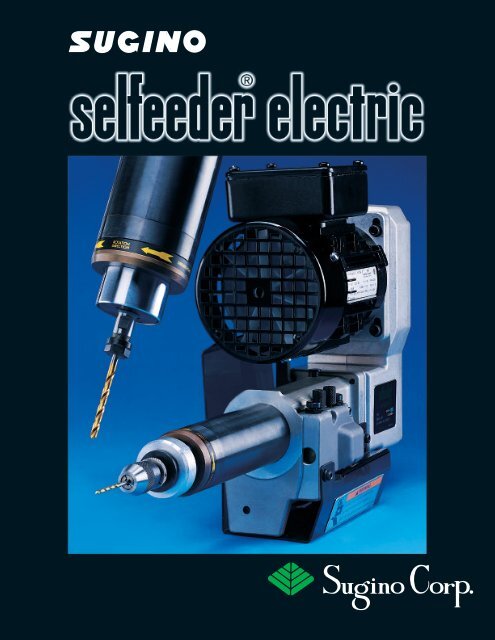
SUGINO GIVES YOU MORE CHOICES FOR AUTOMATINGYOUR DRILLING AND TAPPING OPERATIONSGlobal <strong>Electric</strong> SelfeedersChoose from more than 30 models of cost-effective GlobalSelfeeders, power rated from 1/3 - 1.5 HP. Stroke lengthsfrom 3.15” - 7.87”. Coolant through the tool options available.Varimec Servo SelfeedersVarimec Servo Selfeeders provide strong and accurateball-screw servo feed control drilling. This rugged andcompact unit features ample power, stroke and thrust.The RS-232C port is provided for easy set up andoperation. An option to machining centers.Pneumatic SelfeedersPurely air-driven drilling units, Pneumatic Selfeeders offertremendous versatility. Speeds range from 150 to 17,000RPM. Economical machining for heavy and light industries.Efficient and precise at any angle.<strong>Electric</strong> Ball-Screw Feed Synchro TappersThese Tappers provide up to class 3 thread accuracy. Fastchange pitch feed gears offer pitch feed ranges from 13 TPIto 113 TPI, without changing a lead-screw. Use independentlyor easily integrate into PLC-operated machines.Other Suginoproducts:Roller burnishing toolsand high pressure waterdeburring and cleaning1380 Hamilton Parkway, Itasca, IL 60143equipment (630) 250-8585 Fax: (630) 250-8665tratchford@suginocorp.com(626) 945-1948Fax: (626) 963-1726twilson@suginocorp.com(816) 525-5811Fax: (816) 525-6822rdeforge@suginocorp.com(860) 668-7273Fax: (860) 668-7221hwilson@suginocorp.com(704) 876-3987Fax: (704) 876-1089Catalog No. SFN-605-RC Copyright 2005, Sugino Corp. Printed in U.S.A.