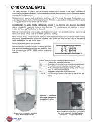
CAST IRON SLUICE GATE WITH"Q-SEAL"FLUSHBOTTOMSEALA "Q-Seal" flushbottom seal gate is used wherever acontinuous smooth opening (without obstructions toimpede solids) is desirable. Typical installations includewastewater settling tanks, aeration tanks, andsedimentation and flocculation basins.CONSTRUCTION FEATURESFlushbottom closures feature a neoprene seal securelycontained at the invert of the frame. The designof this seal provides a flat plane across the bottom ofthe gate without projections into the opening to obstructflow. The seal is mounted on a cast iron bracketand held in place with a corrosion resistant retainer barand fasteners. The seal is firmly supported on threesides, exposing only the flat top side, minimizingdamage from floating objects, wet-dry conditions orsunlight. The seal is easily replaceable without disassemblyof the gate.When a flushbottom seal is used, a smooth roundedprojection on the bottom of the slide replaces thenormal metal seat and seat facing. The slide closesagainst the seal, compressing the neoprene betweenthe slide and frame, making a watertight seal acrossthe bottom of the opening. Bottom wedges are notused as they are not necessary for <strong>Waterman</strong> gateswith a flushbottom closure."Q-Seal "Flushbottom SealRECOMMENDED INSTALLATION CLEARANCESFOR FLUSHBOTTOM GATESGate DiameterorOpening HeightStandardFlangebackGateExtendedFlangebackGateA B A B6" thru 24" 12 7 16 1530" thru 42" 15 7 20 1548" thru 72" 15 9 23 1778" thru 120" 18 10 26 18<strong>Industries</strong>8
TYPICAL SPECIFICATIONSSERIES 7000, 5000, 4000 HEAVY DUTY SLUICE GATESThe following specifications for <strong>Waterman</strong> Heavy Duty Sluice Gates are presented as an aid to the engineer and can beaugmented with additional information to meet specific needs.ScopeThis section covers all heavy duty sluice gates required on the project. Each gate shall be furnished and installed completewith wall thimble or anchor bolts, operating stem, gate lift operator and other appurtenances as specified or needed to makea complete and operable installation.GeneralGates, stems, lifts and other appurtenances shall be the size, type, material and construction as shown on the drawingsand specified herein. Gates shall meet the requirements of AWWA Specifications C-501 (latest revision) or as modified perthese specifications. (They shall be <strong>Waterman</strong> Heavy Duty Sluice Gates or approved equal.) All component parts shall beof the type of material shown, and interchangeable where size and material are the same without grinding, chipping or specialfitting in the field. The gates shall be the product of one manufacturer having five or more years of experience in themanufacture of similar gates for similar use. All mating and sliding parts shall be fully machined. All sluice gate parts,including lift, shall be designed for the heads shown with a minimum safety factor of five.All materials used in the construction of the gates and appurtenances shall be the best suited for the application and shallbe as follows:Frame and Guide RailsThe frame and guide rails shall be cast one-piece construction or may have guides dowelled and bolted to the frame. Framesshall be of the standard flangeback or extended flange type with round or rectangular opening as indicated on the plans andin the sluice gate schedule. A machined dovetail groove for the mounting of the bronze seat facings shall be provided onthe front face of the frame around the full periphery of the opening. The frame shall be provided with cast-on pads whichshall be machined, drilled, and tapped for the mounting of the wedge device. The back of the frame flange shall be machinedto a plane and drilled to match the wall thimble, pipe flange, or anchor bolt pattern. Guide rails shall be of such length asto retain at least one-half of the vertical height of the slide when it is in the fully opened position. A groove running the fulllength of the guide rail shall be accurately machined to receive the slide tongue, with a nominal clearance of 1/16-inch.Cover or SlideThe cover shall be of one piece cast construction with vertical and horizontal ribs, a reinforced pocket to receive the thrustnut, pads to receive the wedges, and a reinforced periphery around the back side of the cover for machining of the dovetailgrooves in which the seating faces shall be mounted. All wedge pads shall be machined, drilled and tapped to receive thewedge devices. The cover shall have fully machined tongues running the full length of each side to properly engage the guiderail grooves. A thrust nut shall be provided to attach the slide to the stem. The nut shall be threaded and, in the case of risingstems, provided with keys on two set screws locked into indents in the stem to prevent rotation of the stem. For non-risingstems, the stem shall turn freely in the thrust nut, to open and close the slides as the stem is rotated.Seating FacesAll seating faces for both covers and frames shall be malleable extruded corrosion resistant material (see materials section)of a shape that will fill and permanently lock in the full width dovetail grooves of the slide and the frame. No other meansof attachment will be allowed. They shall be machined to a 63 micro-inch finish, or better.WedgesAll wedges and wedge blocks shall be solid corrosion resistant material and shall be of sufficient number to provide apractical degree of watertightness. All wedge bearing surfaces and contact faces shall be machined to give maximum contactand wedging action. Wedges shall be fully adjustable, but once set shall not rotate or move from the desired position. Allfasteners and adjustment screws shall be corrosion resistant.Self-Contained Gates with Rising & Non-Rising StemsWhen a self-contained gate is specified, a heavy yoke shall be mounted on the machined pads provided on the upper endsof the guide rails. The yoke shall have a machined bearing surface for the lift nut or pedestal mounting plate. On non-risingstems gates the nut pocket shall be cast on top of the slide so that the stem does not project into the waterway when thegate is fully opened. The thrust generated by gate operation shall be transferred to the yoke by the stem thrust collar or lift.When the operating floor is above the self-contained gate, a stem extension of cold-rolled or stainless steel shall be coupledto the operating stem with a bronze coupling or cast iron stem extension bracket. Operation shall be by a T-handle wrenchor floor stand, shown on the plans and gate schedule. In a T-handle arrangement the stem extension shall be supportedby at least one stem guide or a floor box with integral guide embedded in the operating floor.Flushbottom Sluice GatesWhen a flushbottom closure is specified, a resilient seal shall be attached to the frame so that it is flush with the invert. Itshall be supported by a cast iron bracket which shall be bolted to machined pads provided on the frame. The seal shall beheld in place by a bronze or stainless steel bar which shall be bolted through the seal to the bracket with stainless steelfasteners. The cover (slide) shall be shortened and provided with a smooth rounded surface along the bottom to depress<strong>Industries</strong>9