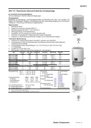
AXM 117S: Motorised drive (with positioner) for unit valves
AXM 117S: Motorised drive (with positioner) for unit valves
AXM 117S: Motorised drive (with positioner) for unit valves
- No tags were found...

You also want an ePaper? Increase the reach of your titles
YUMPU automatically turns print PDFs into web optimized ePapers that Google loves.
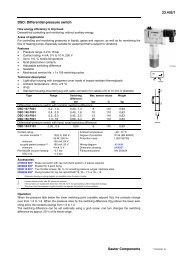
55.011<strong>AXM</strong> <strong>117S</strong>: <strong>Motorised</strong> <strong>drive</strong> (<strong>with</strong> <strong>positioner</strong>) <strong>for</strong> <strong>unit</strong> <strong>valves</strong>How energy efficiency is improvedAutomatic valve adjustment and intelligent cut-out enable maximum energy efficiency.Areas of applicationActuation of through and three-way <strong>unit</strong> <strong>valves</strong> in the VUL, BUL, VXL and BXL series. For controllers<strong>with</strong> continuous output in combination <strong>with</strong> intelligent <strong>unit</strong>ary control systems.Features• Pushing <strong>for</strong>ce 120 N• Fits onto valve <strong>with</strong> M30 × 1.5 thread• Stepping motor <strong>with</strong> control and electronic cut-off• Version <strong>with</strong> control action A or B or adjustable• Maintenance-free gearbox• Suitable <strong>for</strong> retrofitting existing installations using an appropriate adaptor• Operating status control using integrated LED displayTechnical description• Two-part plastic housing, light grey (RAL7035)• Nickel-plated brass nut• Connecting cable, light grey 1.50 m long, 3 × 0.25 mm²• Running time <strong>for</strong> 4 mm stroke: 60 s• Installation position: vertical to horizontal, but not upside downType Direction of Running Stroke Thrust Power Weightoperation 1) times mm N kg<strong>AXM</strong> <strong>117S</strong> F202 1 60 4 120 2) 24 V~ 0,15<strong>AXM</strong> <strong>117S</strong> F302 2 60 4 120 2) 24 V~ 0,15<strong>AXM</strong> <strong>117S</strong> F402 1 or 2 3) 60 4 120 2) 24 V~ 0,15100 %MY07552Directionof operation 2Directionof operation 10 %0 V Output signal y 10 VB07650Power supply 24 V~ ± 15%, 50...60 Hz Ambient temperature –0...50 °CPower consumption on 5 VA Ambient humidity < 75% rhstartingType of protection IP 40 (EN 60529)Control voltage 0...10 V; Ri = 20 kΩ Protection class III (IEC 60730)Control voltage F402 3) 0...10 V; 5,2...10 V; 0...4,8 V Wiring diagram A06147Control current max. 0,5 mA Dimension drawing M06146Max. operating temperature 100 °C at valve Fitting instructions MV 505456Accessories0371235 001 Adaptor <strong>for</strong> fitting to Oventrop <strong>valves</strong> (M30 × 1)0550393 001 Adaptor Danfoss RA2000, 22 mm0371356 001 Adaptor <strong>for</strong> fitting to Beulco or Tobler underfloor-heating distribution stations (M30 × 1)0550393 002 Adaptor Danfoss RAVL, 26 mm0550393 003 Adaptor Danfoss RAV, 34 mm0371361 001 Adaptor <strong>for</strong> fitting to Herz <strong>valves</strong>, type Herz-TS’90 (M28 × 1,5)0371363 001 Adaptor <strong>for</strong> fitting to Tour & Andersson <strong>valves</strong>, type TA/RVT (M28 × 1,5)1) Direction of operation 1: rising 0…10V = <strong>drive</strong> retracts (VXL, VUL, BUL opens, BXL control passage closes).Direction of operation 2: rising 0…10V = <strong>drive</strong> extends (VXL, VUL, BUL closes, BXL control passage opens).2) Pushing <strong>for</strong>ce: min. 100 N, max. 150 N3) The direction of operation and the setting of the control voltage can be set using jumpersOperationDuring commissioning (<strong>with</strong> valve fitted), the actuator moves to the two end positions and memorisesthe number of steps taken to do so. The 0...10 V control signal is then linearly assigned to this effectivestroke. The motor activates the valve and switches off as soon as the stroke position concurs <strong>with</strong>the controller signal. In the end positions or in the event of an overload, the motor is switched off <strong>with</strong>in2 minutes. If the control voltage has not changed <strong>for</strong> 2 hours (in the range 0...0,5 V), the motor –after approx. 2 hours – runs briefly to the end positions and, if necessary, corrects its positionmemory. A complete cycle is per<strong>for</strong>med every 24 hours on the <strong>AXM</strong><strong>117S</strong>F202 and F302 in order toprevent the plug from jamming. The LED lights up when power is applied to the <strong>drive</strong>, and flasheswhen the motor is running.Sauter Components7155011003 07
55.011 <strong>AXM</strong> <strong>117S</strong><strong>AXM</strong><strong>117S</strong>F202 or <strong>AXM</strong><strong>117S</strong>F402, direction of operation 1As the control signal rises, the <strong>drive</strong> spindle retracts and the VUL, VXL through <strong>valves</strong> and the BULthree-way valve (control passage) open. On the BXL three-way valve, the control passage closes.<strong>AXM</strong><strong>117S</strong>F302 or <strong>AXM</strong><strong>117S</strong>F402, direction of operation 2As the control signal rises, the <strong>drive</strong> spindle extends and the VUL, VXL through <strong>valves</strong> and the BULthree-way valve (control passage) close. On the BXL three-way valve, the control passage opens.The black earth lead 1a (24 V~) and the blue earth lead 1b (control voltage) should be connectedtogether to a common earth lead.<strong>AXM</strong><strong>117S</strong>F402After removing the cap on the lid, you can make the following settings using jumpers:-– Auto reset ‘on’ or ‘off’. In the ‘on’ (active) position, the <strong>drive</strong> re-adjusts itself every 24 hours bymoving to the end position or to the internal stop. In the ‘off’ (inactive) position, this readjustmentdoes not occur.– The input signal can be set to either 0...10 V or 5,2...10 V or 0...4,8 V.– Direction of operation 1 or 2 can be selected; factory setting is direction of operation 2.Replace the cap after you have finished making the setting.Engineering and fitting notesNo tools should be used to fit the <strong>drive</strong> onto the valve. In the event of a power failure, the valve can beopened by removing the <strong>drive</strong>. When connecting or transposing the power cable, power must beswitched off.The <strong>drive</strong> must only be fitted on the valve when the <strong>drive</strong> spindle is notextended 100%. Status whendelivered: 50% of stroke.Fitting outdoors. If the devices are fitted outdoors, we recommend that additional measures be takento protect them against the effects of the weather.Standards and regulationsThe <strong>drive</strong> con<strong>for</strong>ms to the relevant EU standards.EMC Directive: CE as per EN 61000-6-3 and EN 61000-6-1Additional technical detailsStrokeRunning timemax. 4,5 mm15 s/mmWiring diagramDimension drawing24 V~2 1 30...10V472 1a 1 b 3A/D1a 1bsc hwarz blaunoir bleublack bluen er o azzuronegro azulsvart bl åzwart blauw2rotrougeredross orojorödrood3weissblancwhitebiancoblancovitw it745562,5VUL / VXLBXLBULL=1,5mB10 094 aM06146aSauter Components7155011003 07
<strong>AXM</strong> <strong>117S</strong> 55.011Jumper setting <strong>for</strong> <strong>AXM</strong><strong>117S</strong>F40212345Auto resetinput yno functionDirectionactive inactive0-10V 5,2-10V 0-4,8V2 1B09297aSauter ComponentsPrinted in SwitzerlandRight of amendment reservedN.B.: A comma between cardinalnumbers denotes a decimal point© Fr. Sauter AG, CH-4016 Basle7155011003 07