DTW Works Master Specification Section 16122 â Wire and Cables ...
DTW Works Master Specification Section 16122 â Wire and Cables ...
DTW Works Master Specification Section 16122 â Wire and Cables ...

Create successful ePaper yourself
Turn your PDF publications into a flip-book with our unique Google optimized e-Paper software.
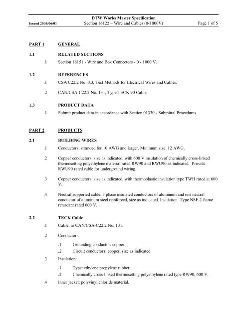
<strong>DTW</strong> <strong>Works</strong> <strong>Master</strong> <strong>Specification</strong>Issued 2005/06/01 <strong>Section</strong> <strong>16122</strong> –<strong>Wire</strong> <strong>and</strong> <strong>Cables</strong> (01000V) Page 1 of 5PART 1GENERAL1.1 RELATED SECTIONS.1 <strong>Section</strong> 16151 <strong>Wire</strong> <strong>and</strong> Box Connectors 0 1000 V.1.2 REFERENCES.1 CSA C22.2 No .0.3, Test Methods for Electrical <strong>Wire</strong>s <strong>and</strong> <strong>Cables</strong>..2 CAN/CSAC22.2 No. 131, Type TECK 90 Cable.1.3 PRODUCT DATA.1 Submit product data in accordance with <strong>Section</strong> 01330 Submittal Procedures.PART 2PRODUCTS2.1 BUILDING WIRES.1 Conductors: str<strong>and</strong>ed for 10 AWG <strong>and</strong> larger. Minimum size: 12 AWG..2 Copper conductors: size as indicated, with 600 V insulation of chemically crosslinkedthermosetting polyethylene material rated RW90 <strong>and</strong> RWU90 as indicated. ProvideRWU90 rated cable for underground wiring..3 Copper conductors: size as indicated, with thermoplastic insulation type TWH rated at 600V..4 Neutral supported cable: 3 phase insulated conductors of aluminum <strong>and</strong> one neutralconductor of aluminum steel reinforced, size as indicated. Insulation: Type NSF2 flameretardant rated 600 V.2.2 TECK Cable.1 Cable: to CAN/CSAC22.2 No. 131..2 Conductors:.1 Grounding conductor: copper..2 Circuit conductors: copper, size as indicated..3 Insulation:.1 Type: ethylene propylene rubber..2 Chemically crosslinked thermosetting polyethylene rated type RW90, 600 V..4 Inner jacket: polyvinyl chloride material.
<strong>DTW</strong> <strong>Works</strong> <strong>Master</strong> <strong>Specification</strong>Issued 2005/06/01 <strong>Section</strong> <strong>16122</strong> –<strong>Wire</strong> <strong>and</strong> <strong>Cables</strong> (01000V) Page 2 of 5.5 Armour: interlocking..6 Overall covering: thermoplastic polyvinyl chloride material..7 Fastenings:.1 One hole steel straps to secure surface cables 50 mm <strong>and</strong> smaller. Two hole steelstraps for cables larger than 50 mm..2 Channel type supports for two or more cables at 1500 mm centers..3 Threaded rods: 6 mm dia. to support suspended channels..8 Connectors:.1 Watertight <strong>and</strong>/or type approved for TECK cable.2.3 MINERALINSULATED CABLES.1 Conductors: solid bare softannealed copper, size as indicated..2 Insulation: compressed powdered magnesium oxide to form compact homogeneous massthroughout entire length of cable..3 Overall covering: annealed seamless copper sheath, Type M1 rated 600 V, 250EC..4 Overall covering: annealed seamless copper sheath type LWM1 rated 600 V, 250EC..5 Outer jacket: PVC applied over sheath where required..6 Two hour fire rating..7 Connectors: st<strong>and</strong>ard as required..8 Termination kits: st<strong>and</strong>ard as required.2.4 ARMOURED CABLES.1 Conductors: insulated, copper, size as indicated..2 Type: AC90..3 Armour: interlocking type fabricated from aluminum strip..4 Type: ACWU90 flame retardant jacket over armour meeting requirements of VerticalTray Fire Test of CSA C22.2 No. 0.3 with maximum flame travel of 1.2 m..5 Connectors: st<strong>and</strong>ard as required.2.5 ALUMINUM SHEATHED CABLE.1 Conductors: copper, size as indicated.
<strong>DTW</strong> <strong>Works</strong> <strong>Master</strong> <strong>Specification</strong>Issued 2005/06/01 <strong>Section</strong> <strong>16122</strong> –<strong>Wire</strong> <strong>and</strong> <strong>Cables</strong> (01000V) Page 3 of 5.2 Insulation: type RA90 rated 600 V..3 Sheath: aluminum applied to form continuous corrugated sheath..4 Outer jacket of PVC applied over sheath for direct burial or wet locations..5 Fastenings for aluminum sheathed cable:.1 One hole steel straps to secure surface cables 25 mm <strong>and</strong> smaller. Two hole steelstraps for cables larger than 25 mm. Use aluminum strap only with singleconductor cable..2 Channel type supports for two or more cables at 1500 mm centers..3 Threaded rods: 6 mm dia. to support suspended channels.2.6 CONTROL CABLES.1 Type LVT: 2 soft annealed copper conductors, sized as indicated, with thermoplasticinsulation, outer covering of thermoplastic jacket.Low energy 300 V control cable:str<strong>and</strong>ed annealed copper conductors sized as indicated, with PVC insulation type TW 40EC polyethylene insulation with shielding of tape coated with paramagnetic materialwire braid over each conductor <strong>and</strong> overall covering of PVC jacket..2.7 NONMETALLIC SHEATHED CABLE.1 Nonmetallic sheathed copper cable type: NMD7 nylon, size as indicated.PART 3EXECUTION3.1 INSTALLATION OF BUILDING WIRES.1 Install wiring as follows:.1 In conduit systems in accordance with <strong>Section</strong> 16133 Conduits, Fastenings <strong>and</strong>Fittings..2 In cable troughs in accordance with <strong>Section</strong> 16135 Cabletroughts..3 In underground ducts in accordance with <strong>Section</strong> 16051 Installation of <strong>Cables</strong> inDucts..4 In trenches in accordance with <strong>Section</strong> 16051 Installation of <strong>Cables</strong> in Trenches..5 In underfloor distribution system in accordance with <strong>Section</strong> 16113 UnderfloorDistribution System.6 In cellular floor raceways in accordance with <strong>Section</strong> 16137 –Cellular FloorRaceway..7 In surface <strong>and</strong> lighting fixture raceways in accordance with <strong>Section</strong> 16505Lighting..8 In wireways <strong>and</strong> auxiliary gutters in accordance with <strong>Section</strong> 16136 –<strong>Wire</strong>ways<strong>and</strong> Auxiliary Gutters.
<strong>DTW</strong> <strong>Works</strong> <strong>Master</strong> <strong>Specification</strong>Issued 2005/06/01 <strong>Section</strong> <strong>16122</strong> –<strong>Wire</strong> <strong>and</strong> <strong>Cables</strong> (01000V) Page 4 of 5.9 Overhead service conductors in accordance with <strong>Section</strong> 16401 ServiceEquipment.3.2 INSTALLATION OF TECK CABLE 0 1000 V.1 Install cables..1 Group cables wherever possible on channels..2 Install cable in trenches in accordance with <strong>Section</strong> 16051..3 Lay cable in cabletroughs in accordance with <strong>Section</strong> 16135..4 Terminate cables in accordance with <strong>Section</strong> 16151 <strong>Wire</strong> <strong>and</strong> Box Connectors 0 1000V.3.3 INSTALLATION OF MINERALINSULATED CABLES.1 Install cable in trenches in accordance with <strong>Section</strong> 16051..2 Run cable exposed, securely supported by straps..3 Support 2 h fire rated cables at 1m intervals..4 Make cable terminations by using factorymade kits..5 At cable terminations use thermoplastic sleeving over bare conductors..6 Install cable in cabletroughs in accordance with <strong>Section</strong> 16135..7 Where cables are buried in cast concrete or masonry, sleeve for entry <strong>and</strong> exit of cables..8 Do not splice cables.3.4 INSTALLATION OF ARMOURED CABLES.1 Group cables wherever possible..2 Install cable in trenches in accordance with <strong>Section</strong> 16051..3 Lay cable in cabletroughs in accordance with <strong>Section</strong> 16135..4 Terminate cables in accordance with <strong>Section</strong> 16151 <strong>Wire</strong> <strong>and</strong> Box Connectors 0 1000V.3.5 INSTALLATION OF ALUMINUM SHEATHED CABLE.1 Group cables wherever possible on channels..1 Install cable in trenches in accordance with <strong>Section</strong> 16 051..2 Lay cable in cabletroughs in accordance with <strong>Section</strong> 16135.
<strong>DTW</strong> <strong>Works</strong> <strong>Master</strong> <strong>Specification</strong>Issued 2005/06/01 <strong>Section</strong> <strong>16122</strong> –<strong>Wire</strong> <strong>and</strong> <strong>Cables</strong> (01000V) Page 5 of 5.3 Terminate cables in accordance with <strong>Section</strong> 16151 <strong>Wire</strong> <strong>and</strong> Box Connectors 01000V.3.6 INSTALLATION OF CONTROL CABLES.1 Install control cables in conduit, under floor raceways, cable troughs <strong>and</strong> undergroundducts by direct burial as indicated..2 Ground control cable shield.3.7 INSTALLATION OF NONMETALLIC SHEATHED CABLE.1 Install cables..2 Install straps <strong>and</strong> box connectors to cables as required.END OF SECTION