NI-281E - Ettore Cella SPA
NI-281E - Ettore Cella SPA
NI-281E - Ettore Cella SPA
- No tags were found...

You also want an ePaper? Increase the reach of your titles
YUMPU automatically turns print PDFs into web optimized ePapers that Google loves.
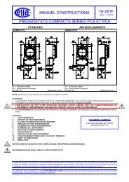
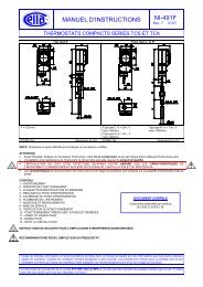
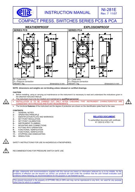
INSTRUCTION MANUAL<strong>NI</strong>-<strong>281E</strong>Rev. 7 11/07valve is closed with a plug to prevent the outlet of the processfluid caused by the incorrect use of said valve.Mount a three piece joint onto the threaded attachment of theinstrument to permit the easy mounting or removal of theinstrument itself.Carry out the connection using a flexible tube in such a way thatthe tube itself does not force the instrument attachment due tovariations in temperature.Ensure that all the pressure connections are airtight. It isimportant that there are no leakages in the circuit.Close the root valve and the relative drain device. Close theservice valve fitted with a safety plug.7.3 ELECTRICAL CONNECTIONSIt is recommended to carry out the electrical connectionsaccording to the applicable standards. In case of explosionproofinstruments (series PCA) see also the Standard EN-60079-14and EN-61241-14. If the electrical connection is carried out in aprotected tube, it shall be made so that condensate is preventedfrom entering instrument enclosure.The arrangement shown in Fig. 7 or 8 is therefore recommended.CAUTION: fittings used for the electrical connection of thepressure switch series PCA (explosionproof) shall be certified IinATEX generation and shall guarantee instrument degree ofprotection (IP65).Check that there is no power in the lines.Remove the cover and carry out the cabling and connections tothe terminal block (see Fig. 2).Flexible cables with a maximum section of 1,2 mm 2 (16AWG) arerecommended using the pre-insulated thimbles with a maximumdiameter of 2,5 mm supplied with the instrument.When inserting cables into the enclosure pay attention not toforce the microawitch with cable or tools, otherwise instrumentcalibration or even its operation could be compromised. Themicroswitch has been factory mounted and positioned in order toobtain the best performances. Any tampering made on sitewithout following instructions authorised by the E. CELLA <strong>SPA</strong>may result in instrument malfunction.Ensure that no deposits or wire ends remain inside the case.Once the connection operations have been completed, replacethe cover and ensure that it is properly sealed and blocked. SeeFig. 3.7.4 SPECIAL NOTE FOR INSTALLATION OFCATEGORY 1 / 2 G and 1 / 2 D PRESSURE SWITCHESFig. 6 -Installation of Group II Cat. 1 / 2 D instruments8 - PUTTING INTO OPERATIONAs the signal transmitted by the instrument is used in a complexsystem, it is necessary that the means of putting it into operationare established by personnel in charge of the plant.The instrument comes into operations as soon as the root valve isopened. Any possible drainage of the connection tubing can becarried out by removing the safety plug and opening the servicevalve with the necessary caution.In case of explosionproof instruments (Series PCA), initialinspections are to be carried out according to customerprocedures and at least in accordance with Standard EN-6007-17and EN-61241-179 - FUNCTIONAL VERIFICATIONThis will be carried out according to the Client’s controlprocedures.The explosionproof instruments (series PCA) installed inexplosive atmospheres for the combustible dust presence, mustbe periodically cleaned up externally in order to avoid dustaccumulating.Series PCS instruments can be verified on the plant if installed asillustrated in Fig. 7 and 8.Explosionproof pressure switches (series PCA) can be installed The instruments Series PCA may be checked on site only ifon processes requiring apparatus of group II category 1 in an apparatus suitable for explosive atmosphere are used andambient requiring apparatus of group II category 2 (see Fig. 5 and provided that the electric line is not energized.6). If this is not the case it is necessary to stop operation, dismountFig. 5 - Installation of Group II Cat. 1 / 2 G instrumentsby means of the three piece joints and carry out the verification ina test room.CAUTION: do not open the cover of explosionproof pressureswitches (Series PCA) when energized, in explosiveatmospheres.Verification consists in check the calibration value and possiblyregulating the adjustment bush (see §5).In case of explosionproof instruments (Series PCA), inspectionsof the electrical installation are to be carried out also according tocustomer procedures and at least in accordance with StandardEN-60079-17 and EN-61241-1710 -
INSTRUCTION MANUAL<strong>NI</strong>-<strong>281E</strong>Rev. 7 11/07TROUBLESHOOTINGIMPORTANT NOTE: operations involving replacement of essential components must be carried out at our workshop, especiallyfor instruments with explosionproof certificate; this is to guarantee the user the total and correct restoration of the productoriginal characteristics.MALFUNCTION PROBABLE CAUSE REMEDY• Permanent deformation of the sensitive element • Recalibrate or replace the sensitive element.due to fatigue or excess over-ranges.• Variation of the elastic features of the sensitive • Recalibrate or replace the sensitive element withSet point shiftelement due to its chemical corrosion.another made of a suitable material. If necessaryapply fluid separator.• O-ring wear (only PCS2P, PCS3P, PCA2P and • Replace the piston subgroup and recalibrate.PCA3P).• O-ring wear (only PCS2P, PCS3P, PCA2P and • Replace the piston subgroup and recalibrate.PCA3P).Poor repeatability• Air bubbles or condensation (only for types with • Drain the process connection lines and if necessarypressure < 1 bar).modify them.Slow responseNo actuation orundue actuation• Clogged or obstructed connection line.• Root valve partially closed.• Too viscous fluid.• Root valve closed.• Microswitch contacts damaged.• Loosened electrical joints.• Interrupted or short-circuited.Undue actuation • Accidental shocks. • Modify the mounting.• Check and clean line.• Open valve.• Provide instrument with suitable fluid separator.• Open the valve.• Replace the microswitch.• Check all electrical joints.• Check the conditions of the electric line.11 - STOPPING AND DISMOUNTINGBefore proceeding with these operations ensure that the plant ormachines have been put into the conditions foreseen to allowthese operations.With reference to figures 7 or 8Remove the power supply (signal) from the electrical line.Close the root valve (6) and open the drain.Remove the plug (2), open the valve (3) and wait until the processfluid has drained from the tubing through the drain.Do not dispose of the process fluid into the environment, if thiscan cause pollution or damage to people.Unscrew the three piece joint (8).CAUTION: do not open the cover of explosionproof pressureswitches (Series PCA) when energized, in explosiveatmospheres.Unscrew the three piece joint (10) (electrical cable tubing).Remove the instrument cover and disconnect the electrical cablesfrom the terminal block and earth screws.Remove the screw fixing the case to the panel (or pipe) andremove the instrument, taking care to slide the electricalconductors out from the case.Mount instrument cover. Insulate and protect cables around, ifany. Temporarily plug pipes not connected to the instrument (e).In case of explosionproof instruments (series PCA) it isrecommended to follow - at least – the standard EN-60079-17and EN-61241-17 for the withdrawal from service of electricalapparatus.12 - DEMOLITIONThe instruments are mainly made of stainless steel andaluminium and therefore, once the electrical parts have beendismounted and the parts coming into contact with fluids whichcould be harmful to people or the environment have been properlydealt with, they can be scrapped.
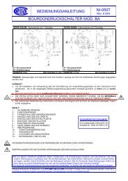
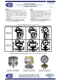
INSTRUCTION MANUAL<strong>NI</strong>-<strong>281E</strong>Rev. 7 11/07WEATHERPROOFFig. 7 - Example of connections Fig. 8 - Example of connectionsEXPLOSIONPROOFFig. 9 - Surface or bracket mounting for 2" pipe(weatherproof and explosionproof instruments)LEGEND1 - Fitting 9 - "T" fitting2 - Drain plug 10 - Three piece fitting3 - Service valve 11 - Blocking joint4 - Piping 12 - Curve5 - Three piece fitting 13 - M5 screws (No. 2)6 - Root valve with drain 14 - Bracket for 2" pipe7 - Process piping 15 - Vertical pipe8 - Three piece fitting 16 - Horizontal pipeNOTE: With gas or vapour process fluid, the instrument mustbe positioned higher than the pipe inlet (see Fig. 8). With aliquid process fluid, the instrument can be positioned higher orlower, indifferently (see Fig. 7 and 8). In this case, during setpoint calibration the negative or positive head must be takeninto account (distance h in Fig.7 and 8).ETTORE CELLA <strong>SPA</strong> Viale de Gasperi, 48 - Casella Postale (P.O. Box) 96 - I 20010 Bareggio (MILANO) ITALYTelefoni +39 029036.1146/1237/1241 - FAX +39 029036.1331 e-mail: cella@ecellaspa.com