Automated Transfer Vehicle (ATV) - ESA
Automated Transfer Vehicle (ATV) - ESA
Automated Transfer Vehicle (ATV) - ESA

Create successful ePaper yourself
Turn your PDF publications into a flip-book with our unique Google optimized e-Paper software.
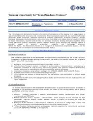
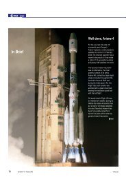
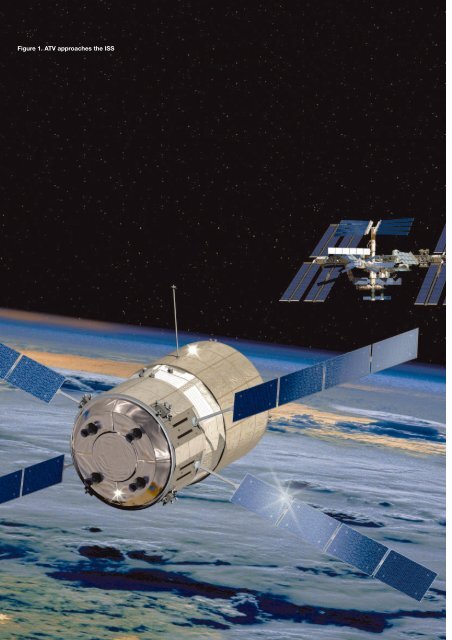
Figure 1. <strong>ATV</strong> approaches the ISS
<strong>Automated</strong> <strong>Transfer</strong> <strong>Vehicle</strong> (<strong>ATV</strong>)<br />
Structural and Thermal Model Testing at<br />
ESTEC<br />
P. Amadieu, G. Beckwith, B. Dore<br />
<strong>ATV</strong> Project, <strong>ESA</strong> Directorate of Manned Spaceflight and Microgravity,<br />
Les Mureaux, France<br />
J.P. Bouchery<br />
EADS Launch <strong>Vehicle</strong>s, Space Programme Directorate, <strong>ATV</strong> Programme,<br />
Les Mureaux, France<br />
V. Pery<br />
EADS Launch <strong>Vehicle</strong>s, Systems Design and Tests Directorate,<br />
Systems Tests Department, Les Mureaux, France<br />
<strong>ATV</strong> description<br />
<strong>ATV</strong> capabilities<br />
The <strong>Automated</strong> <strong>Transfer</strong> <strong>Vehicle</strong> (<strong>ATV</strong>) being<br />
developed by <strong>ESA</strong> is an unmanned vehicle that<br />
can be configured to provide the International<br />
Space Station (ISS) with up to 5500 kg of dry<br />
supplies (e.g. hardware, food and clothes) and<br />
liquid and gas supplies (up to 840 kg of water;<br />
up to 100 kg of gases (air, nitrogen, oxygen); up<br />
to 860 kg of refuelling propellant). <strong>ATV</strong> can<br />
provide propulsion support to the ISS by using<br />
up to 4700 kg of propellant. The total net<br />
payload is estimated to be at least 7500 kg.<br />
Finally, <strong>ATV</strong> can also remove up to 6500 kg of<br />
waste from the Station.<br />
The <strong>ATV</strong> Structural and Thermal Model (STM) test campaign began at<br />
the ESTEC Test Centre in October 2001. <strong>ATV</strong>’s capabilities, mission,<br />
configuration and development logic are outlined. The STM Test<br />
Campaign and test objectives are then detailed. Some special<br />
requirements imposed by <strong>ATV</strong>’s size are described. The main test<br />
results and lessons learned are summarised.<br />
At least eight <strong>ATV</strong> flights to the ISS are planned<br />
as part of the European contribution to<br />
supporting ISS operations (Fig. 1).<br />
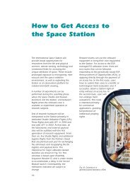
<strong>ATV</strong> configuration<br />
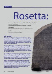
The <strong>ATV</strong> vehicle is composed of two elements<br />
(Fig. 2): the spacecraft (SC; including solar<br />
array) and Integrated Cargo Carrier (ICC).<br />
The <strong>ATV</strong> spacecraft comprises:<br />
– the Separation and Distancing Module (SDM),<br />
which provides the mechanical interface with<br />
Ariane-5 and <strong>ATV</strong>’s separation and distancing<br />
from the launcher;<br />
automated transfer vehicle<br />
– the Equipped Propulsion Bay (EPB), which<br />
accommodates most of the Propulsion and<br />
Reboost Subsystem (some thrusters are also<br />
located on the forward part of the ICC);<br />
– the Equipped Avionics Bay (EAB), which<br />
accommodates most of the avionics equipment<br />
(some avionics items such as rendezvous<br />
sensors are located in the ICC and EPB);<br />
– the Solar Generation System (SGS), which<br />
includes four 4-panel deployable solar wings,<br />
each with its own drive mechanism.<br />
The ICC accommodates all cargo apart from<br />
the reboost propellant (carried in the<br />
spacecraft) and consists of:<br />
– the Equipped Pressurised Module (EPM),<br />
which accommodates dry cargo in dedicated<br />
payload racks. ISS waste is carried for the<br />
destructive reentry part of the <strong>ATV</strong> mission;<br />
– the Equipped External Bay (EEB), which is an<br />
unpressurised assembly to house water, gas<br />
and refuelling propellant tanks;<br />
– the Russian Docking System (RDS), which<br />
provides capture and release for docking<br />
with and departure from the ISS. Several<br />
RDS models, including for the first <strong>ATV</strong>, are<br />
being provided by Russia as a barter for the<br />
European Data Management System that is<br />
currently operating in the Station’s Zvezda<br />
Russian Service Module.<br />
The ICC and SC are protected by the external<br />
Meteoroid and Debris Protection System<br />
(MDPS) shield.<br />
<strong>ATV</strong> development logic and main system<br />
models<br />
The <strong>ATV</strong> flight segment assembly, integration<br />
95
ulletin 111 — august 2002<br />
96<br />
10773<br />
Figure 2. <strong>ATV</strong> subassemblies and dimensions<br />
INTEGRATED<br />
CARGO CARRIER<br />
EQUIPPED<br />
PRESSURIZED<br />
MODULE (EPM)<br />
4916<br />
3330<br />
SPACECRAFT<br />
SUBASSEMBLY<br />
2000<br />
RUSSIAN DOCKING<br />
SYSTEM (RDS)<br />
EQUIPPED EXT.<br />
BAY (EEB)<br />
EQUIPPED<br />
AVIONICS BAY (EAB)<br />
EQUIPPED<br />
PROPULSION<br />
BAY (EPB)<br />
SEPARATION AND<br />
DISTANCING MODULE<br />
(SDM)<br />
PROPELLANT TANKS<br />
MAIN THRUSTERS<br />
ATTITUDE CONTROL THRUSTERS<br />
Ø 4482 MAXI MDPS WITHOUT MLI<br />
MDPS CC<br />
GAS, WATER AND RFS<br />
AVIONICS EQUIPMENT<br />
CHAINS (AEC)<br />
RADIATORS EAB<br />
MDPS EPB<br />
SOLAR GENERATION<br />
SYSTEM (SGS)<br />
ATTITUDE CONTROL AND<br />
BRAKING THRUSTERS<br />
SEPARATION PLANE
and verification during Phase-C/D uses three<br />
system-level models: STM, Electrical Test<br />
Model (ETM) and Proto-Flight Model (PFM).<br />
The STM is being used for environmental tests<br />
in the ESTEC Test Centre. After these tests, the<br />
SC will be subjected to static tests at<br />
Contraves (CH). The ICC external bay will be<br />
subjected to further dynamic and static tests<br />
(together with a flight-standard pressurised<br />
module). The STM pressurised module will be<br />
refurbished at Alenia (I) and eventually used for<br />
crew training at the European Astronaut Centre<br />
in Cologne (D).<br />
The ETM is being used for functional<br />
qualification testing of the <strong>ATV</strong> and for a first set<br />
of vehicle/ground segment compatibility tests.<br />
After initial integration and electrical testing of<br />
the EAB ETM at Astrium SAS (F), the full <strong>ATV</strong><br />
ETM (including the ETM models of the avionic<br />
equipment in the ICC and EPB) will be<br />
integrated at EADS Launch <strong>Vehicle</strong>s.<br />
The PFM, now named ‘Jules Verne’, will be<br />
subjected to the following environmental and<br />
functional tests:<br />
– acoustic<br />
– electromagnetic compatibility<br />
– solar wing deployment<br />
– clampband release<br />
–thermal test (EAB level)<br />
– final set of vehicle/ground segment<br />
compatibility tests<br />
– complementary electrical and functional<br />
qualification tests<br />
– functional acceptance.<br />
The <strong>ATV</strong> Flight Segment prime contractor for<br />
Phases-C/D (development, manufacture,<br />
integration of first vehicle and associated<br />
ground support equipment, as well as <strong>ATV</strong><br />
qualification) is EADS Launch <strong>Vehicle</strong>s (Les<br />
Mureaux, F). The main contractors responsible<br />
for the subsystems and/or the <strong>ATV</strong> subassemblies<br />
are:<br />
– Astrium GmbH (Bremen, D), propulsion and<br />
reboost subsystem, SC integration<br />
–Alenia Spazio (Turin, I), ICC<br />
– Astrium SAS (Toulouse, F), avionics subsystem,<br />
EAB integration<br />
– Contraves (Zurich, CH), SC structure subsystem<br />
–Dutch Space (Leiden, NL), solar array.<br />
Testing at ESTEC<br />
The main objective of the STM test campaign is<br />
to verify the vehicle’s mechanical and thermal<br />
behaviour. Since many <strong>ATV</strong> components are<br />
either derived or directly reused from previous<br />
programmes, the dynamic tests are of<br />
particular importance for confirming their<br />
adequacy for <strong>ATV</strong> to save on delta-qualification<br />
or redesign. Another goal of the vibration tests<br />
(acoustic, sine) is to characterise the vibration<br />
environment experienced by <strong>ATV</strong> payloads in<br />
the payload racks.<br />
The STM campaign began at the end of<br />
October 2001. Figure 3 shows the test<br />
sequence.<br />
STM representativity<br />
The SDM model consists of a flightrepresentative<br />
structure, with a real clampband<br />
separation device equipped with connectors,<br />
but no distancing spring. The rest of the SC<br />
structure has only minor differences from the<br />
Flight Model. Its equipment mock-ups are<br />
dynamically and thermally representative; the<br />
stiffness at bracket interfaces is representative<br />
of the Flight Model, and there is 80% of the<br />
EPB harness and plumbing. Propulsion<br />
subsystem tanks are fillable structural mockups.<br />
The Thermal Control System is fully flightrepresentative.<br />
One solar wing is mechanically<br />
flight representative; the other three are<br />
simulated by single-panel mock-ups (identical<br />
mass and area as folded wings).<br />
The ICC STM is dynamically representative of<br />
the Flight Model. The EPM (replaced by a<br />
special mock-up for thermal testing) structure<br />
includes a cylindrical shell and aft and forward<br />
conical parts. The EEB shows minor<br />
differences with respect to Flight Models.<br />
Racks are flight-standard. The Russian<br />
Docking System (RDS) is a mechanically and<br />
thermally representative mock-up. The ICC<br />
forward cone features a mechanical mock-up<br />
automated transfer vehicle<br />
Sep Oct Nov Dec Jan Feb Mar Apr May Jun Jul Aug Sep Oct<br />
STM Test Campaign<br />
Acoustic Test<br />
25/10<br />
Modal Survey Tests<br />
17/12<br />
Dynamic & SDM Tests<br />
15/04<br />
Shock Tests<br />
06/05<br />
SGS Deployment Tests<br />
03/06<br />
Thermal Test<br />
17/06<br />
12/08 EMC Test<br />
21/08<br />
Packaging<br />
End of campaign<br />
10/09<br />
Figure 3. STM ESTEC test<br />
campaign sequence<br />
97
ulletin 111 — august 2002<br />
98<br />
Figure 4. <strong>ATV</strong> on the<br />
Acoustic Stand in LEAF<br />
of a rendezvous sensor, on its dedicated<br />
support. ICC gas tanks are structural models<br />
with masses representative of filled tanks.<br />
Refuelling System (RFS) kits and water tanks<br />
are fillable structural models, with dummy<br />
valves and partial plumbing.<br />
Acoustic test<br />
Characterisation of the vibro-acoustic response<br />
of <strong>ATV</strong> to the acoustic levels induced by the<br />
Ariane-5 launch and flight was the major<br />
requirement of the acoustic test. The final goal<br />
was to compare acoustic and random vibration<br />
levels to those specified for <strong>ATV</strong>’s major<br />
components and equipment. Tests were<br />
performed in December 2001 in the Large<br />
European Acoustic Facility (LEAF) at ESTEC.<br />
<strong>ATV</strong> with a total mass of 15 t (low loaded<br />
configuration) was mated with the Acoustic<br />
Uncoupling Stand (AUS, Fig. 4). This adapter<br />
dynamically uncouples <strong>ATV</strong> from the ground,<br />
as well as positioning it inside LEAF’s homogeneous<br />
acoustic field. Uncoupling was<br />
achieved at the top of the adapter through<br />
rubber isolator mounting pads. A dry-run test<br />
involving the AUS alone was performed a few<br />
weeks before the STM test itself.<br />
The test sequence was:<br />
– low-level run: overall level 141 dB for 66 s<br />
–intermediate-level run: overall level 143 dB<br />
for 60 s<br />
– qualification-level run: overall level 147 dB for<br />
120 s<br />
– low-level run (to check sensors’ individual<br />
responses and to assess structural integrity<br />
after the testing): overall level 141 dB for 60 s.<br />
Achievement of homogeneity and the specified<br />
test spectrum took less than a minute for each<br />
test run. After the first run, microphone<br />
positioning was optimised; they were moved<br />
further from the STM, outside the acoustic<br />
homogeneous field. This unusual setting was<br />
due to the STM’s size, which fully occupied the<br />
LEAF acoustic homogeneous field. During the<br />
qualification-level run, nitrogen aerodynamic<br />
noise at 4 kHz in the LEAF made the target<br />
input level in this non-critical band impossible<br />
to tune precisely (higher levels than required<br />
were achieved).<br />
All these tests were successfully<br />
performed within 4 days. Qualification<br />
random levels for equipment are<br />
in the process of being confirmed by<br />
test-result analysis.<br />
Modal survey<br />
The test characterised the global<br />
dynamic behaviour of the complete<br />
<strong>ATV</strong>: the main longitudinal and lateral<br />
structural eigenmodes of the <strong>ATV</strong>,<br />
and (when uncoupled) the eigenmodes<br />
of the vehicle’s main<br />
components. Eigenfrequencies and<br />
shapes, effective and generalised<br />
masses and damping factors of the<br />
eigenmodes were produced by<br />
modal survey tests. These results are<br />
being used for updating the <strong>ATV</strong><br />
mathematical model for <strong>ATV</strong>/<br />
Ariane-5 coupled load analysis.<br />
The modal survey logic was based<br />
on two test configurations with<br />
different fluid and dry-cargo loadings.<br />
In reality, <strong>ATV</strong> will carry a wide range<br />
of payload combinations. Both<br />
configurations had a mass of around 20 t. The<br />
first used an extreme payload distribution<br />
chosen to produce maximum dynamic<br />
coupling between SC and ICC. The second<br />
was closer to a probable payload distribution<br />
for the first <strong>ATV</strong> flight, with clearly separated SC<br />
and ICC eigenmodes. The STM was interfaced<br />
with the ground by the Mechanical<br />
Interface (MIF) test adapter. Its double conical<br />
shape ensured that the high lateral<br />
eigenfrequency did not interfere with <strong>ATV</strong>’s<br />
main eigenmodes during the tests.<br />
Two methods were possible for performing the<br />
tests:<br />
–local exciters in LEAF, with its seismic block<br />
of around 2000 t of concrete. The test principle
would then be phase resonance (direct modal<br />
identification): broad-band low-level sweeps,<br />
followed by tuned sine excitation (for<br />
identification of primary target eigenmodes),<br />
and narrow-band sweeps (for determination of<br />
modal parameters and non-linearities). Further<br />
target eigenmode information would be<br />
available through broad-band sweep analysis<br />
–the HYDRA hydraulic shaker (3-axis excitation<br />
through eight actuators of 630 kN; four on the<br />
vertical axis, two on each lateral axis). The<br />
approach would be phase separation with<br />
broad-band low-level sweeps through sine<br />
excitation for eigenmode identification,<br />
customised broad-band sweeps and analysis<br />
to determine modal parameters and assess<br />
non-linearities. Use of HYDRA implies recording<br />
of temporal data, requiring further analysis<br />
to derive Frequency Response Functions.<br />
The choice was driven by one HYDRA main<br />
constraint: lateral excitation along one axis<br />
results in non-negligible 3-axis excitation owing<br />
to ‘cross-talk’ effects. In order to limit risks for<br />
the success of the test, the decision was taken<br />
to use local exciters for lateral excitation in<br />
LEAF, and to use HYDRA only for longitudinal<br />
tests since this allowed higher load levels,<br />
which are useful for the estimation of damping.<br />
Following acoustic tests, the LEAF lateral test<br />
on the first configuration started in February<br />
2002. IABG provided four exciters: two of<br />
2.2 kN were placed at the SC/ICC interface<br />
level and two of 7 kN were placed at the ICC<br />
upper handling ring level. The IABG data<br />
acquisition system recorded information from<br />
around 580 accelerometers and 50 strain<br />
gauges that measured SC/ICC and SC/adapter<br />
interface force fluxes. Figure 5 shows the test<br />
set-up.<br />
Since the MIF adapter was designed to<br />
interface with the HYDRA table, its use in LEAF<br />
required a special metal plate, bolted and<br />
torqued to the ground, onto which the MIF was<br />
fixed. To ensure proper clamping of the test<br />
specimen to LEAF’s seismic block, an epoxy<br />
layer was laid between the plate and ground.<br />
The test configuration was finally set up after a<br />
floor compliance measurement with only the<br />
MIF mated via the metal plate to the ground.<br />
The lateral testing took 4 days, including broadband<br />
and narrow-band sweeps, and identified<br />
all target eigenmodes. Raw results were<br />
corrected with respect to ground effects<br />
(unsymmetrical stiffness at the base of the test<br />
set-up) using forces and accelerations<br />
measured on the test floor and test adapter.<br />
A quick longitudinal test was added in LEAF<br />
using one local exciter hanging from a crane<br />
and mated with the ICC upper handling ring. Its<br />
purpose was to prepare for HYDRA runs by<br />
identifying primary longitudinal target<br />
eigenmodes.<br />
The transfer of STM and MIF to HYDRA finally<br />
allowed the main longitudinal runs to begin<br />
(Fig. 6). Both configurations underwent<br />
longitudinal modal survey tests on HYDRA and<br />
automated transfer vehicle<br />
Figure 5. Lateral modal<br />
survey test set-up with <strong>ATV</strong><br />
on MIF<br />
Figure 6. Longitudinal modal<br />
survey test set-up on<br />
HYDRA<br />
99
ulletin 111 — august 2002<br />
100<br />
Figures 7a-c. Achieved<br />
levels for dynamic tests<br />
provided satisfactory results, confirming the<br />
test predictions.<br />
Further lateral tests were performed on<br />
HYDRA. Owing to the complex rocking motion<br />
of the table in specific frequency bands, the<br />
individual behaviours of <strong>ATV</strong> and the table<br />
proved difficult to decorrelate, so it was not<br />
possible to assess precisely the associated<br />
damping factors. However, those runs<br />
confirmed the eigenfrequencies of the first<br />
bending modes.<br />
m/s 2<br />
a<br />
m/s 2<br />
b<br />
m/s 2<br />
c<br />
X axis dynamic levels<br />
Y axis dynamic levels<br />
Z axis dynamic levels<br />
Frequency<br />
Frequency<br />
Frequency<br />
It was considered that these tests had provided<br />
sufficient information, so the test sequence was<br />
shortened and the second set of LEAF lateral<br />
testing was cancelled.<br />
Dynamic qualification<br />
Considering <strong>ATV</strong>’s high mass (up to 20.75 t)<br />
and ESTEC’s testing capabilities, the initial logic<br />
was of qualification in stages: Finite Element<br />
Model (FEM) updating after modal test,<br />
updated Ariane-5/<strong>ATV</strong> coupled-load analysis<br />
to assess dynamic qualification levels, test<br />
predictions for the SC and ICC separately, and<br />
separate dynamic tests for the SC and ICC.<br />
However, given the good correlation between<br />
the STM FEM predictions and the modal<br />
results, and HYDRA’s proven capability during<br />
modal survey tests to apply the required<br />
dynamic levels to the combined (<strong>ATV</strong> and MIF)<br />
mass of 24 t, the opportunity was taken to<br />
make use of the full STM configuration (without<br />
SDM). Thus, the new logic consisted of<br />
performing iterative runs to achieve levels as<br />
high as possible, taking into account the<br />
maximum allowable levels for <strong>ATV</strong>’s main<br />
components and critical equipment, as well as<br />
the expected Ariane-5 dynamic<br />
environment. Test-result evaluation and<br />
post-test analyses would then verify<br />
that <strong>ATV</strong> can withstand the Ariane-5<br />
environment with adequate margins.<br />
After analysis of the modal survey<br />
results and following a thorough <strong>ATV</strong><br />
inspection, some additional sensors<br />
were integrated into the STM. Tests<br />
along the X- (vertical) and Y- (lateral)<br />
axes were then first performed:<br />
intermediate-level runs (around 80% of<br />
flight limit levels) to record all available<br />
channels, then assessment of transfer<br />
functions for all measurement points to<br />
deduce the next run at increased<br />
levels.<br />
Coupling between the shaker and the<br />
test article resulted in artificial damping<br />
at the eigenfrequency of the first <strong>ATV</strong><br />
bending mode. The input levels were<br />
adapted around this eigenfrequency to<br />
obtain the correct force at the <strong>ATV</strong><br />
interface. Interactions between the test<br />
article and the shaker table induced<br />
control difficulties, and therefore limited<br />
the input levels at specific frequencies.<br />
In this case, the finally applied levels<br />
were adjusted to reach qualification<br />
levels on heavy items such as<br />
propellant tanks.<br />
These two first dynamic qualification<br />
tests were completed successfully.<br />
Given the test configuration symmetry, Z-axis<br />
input levels were the same as those specified<br />
along the Y-axis. Figures 7a-c show the final<br />
applied input levels at <strong>ATV</strong>’s base. Differences<br />
between the specified and achieved levels were<br />
caused by either notching or control effects.<br />
The qualification testing in three axes was<br />
considered to be successfully completed at the<br />
end of April 2002. The final Ariane-5/<strong>ATV</strong><br />
coupled-load analysis aims to confirm the input<br />
levels used during the tests.<br />
Thanks to HYDRA, the <strong>ATV</strong> STM is the heaviest<br />
and largest specimen ever subjected to high
level sine vibration testing for an <strong>ESA</strong><br />
programme.<br />
The sine-test specifications for equipment<br />
were refined on the basis of the results of<br />
the qualification tests. In particular,<br />
qualification vibration specifications for<br />
<strong>ATV</strong>’s Russian equipment, originally<br />
qualified for launch on Russian vehicles,<br />
are in the process of being confirmed. This<br />
would avoid modification of those items<br />
when used on <strong>ATV</strong>.<br />
Mechanical qualification testing will be<br />
completed by static tests on the primary<br />
structure and by pressure integrity tests on<br />
the pressurised module.<br />
<strong>ATV</strong> (including SDM) modal test<br />
The 2 m-high SDM cylindrical adapter was<br />
developed for <strong>ATV</strong> to interface directly with<br />
Ariane-5’s 3936 mm diameter. The SDM<br />
adapter includes a clampband separation<br />
system that was developed specially for<br />
<strong>ATV</strong>’s large diameter. This adapter uses the<br />
new ‘clamp ring separation system’<br />
technology, which offers the advantage of<br />
generating low shock levels.<br />
In order to assess the influence of the adapter<br />
on <strong>ATV</strong>’s global dynamic behaviour, it was<br />
decided to perform additional characterisation<br />
tests. The complete <strong>ATV</strong> launch configuration<br />
(including SDM) was vibration-tested on<br />
HYDRA in the longitudinal and lateral directions<br />
(low levels, X and Y excitations; Fig. 8). The<br />
tests verified the compliance of <strong>ATV</strong>’s (including<br />
SDM) first lateral eigenfrequency with Ariane-<br />
5’s requirements (i.e. this eigenfrequency<br />
should be high enough to avoid influencing<br />
launcher behaviour).<br />
Shock tests<br />
Shock tests involved a complete <strong>ATV</strong>/SDM<br />
configuration hoisted in the HYDRA<br />
Preparation Area (Fig. 9). The first shock test<br />
(the ‘Shogun’ test) dealt with the <strong>ATV</strong> external<br />
shock from the jettisoning of Ariane’s fairing. A<br />
dedicated pyrotechnic device (Shogun) was<br />
provided by Arianespace to generate these<br />
representative shock levels at the SDM<br />
interface. This device was made of a<br />
pyrotechnic linear cord charge inside a<br />
weakened aluminium structure (3936 mm<br />
diameter). The shock wave was generated by<br />
the expansion of the tube causing a controlled<br />
rupture of the lower flange screw section. A<br />
spacer (a 260 mm-diameter cylinder developed<br />
for <strong>ATV</strong> ground integration operations) provided<br />
the interface between the SDM and Shogun,<br />
and was intended to create the proper shock<br />
level at SDM’s lower interface.<br />
automated transfer vehicle<br />
Figure 8. <strong>ATV</strong> (with SDM)<br />
modal tests on HYDRA<br />
Figure 9. <strong>ATV</strong> shock test<br />
set-up in the HYDRA<br />
preparation area<br />
101
ulletin 111 — august 2002<br />
Figure 10. Solar wing under<br />
the deployment rig<br />
102<br />
A dry-run at the end of March 2002<br />
demonstrated that Shogun produced the<br />
required shock levels. The STM Shogun test<br />
was successfully completed at the end of May.<br />
The second shock test concerned the<br />
clampband release. The Shogun and spacer<br />
were removed, and SDM was held to prevent<br />
its lower half falling after release. The test used<br />
shock sensors and two high-speed cameras<br />
(1000 frames/s). The clampband was<br />
successfully released after exposure to the<br />
Shogun shock.<br />
The shock transfer functions from the bottom<br />
of the <strong>ATV</strong> to the most critical equipment were<br />
measured. It was verified that the shock at the<br />
base of ICC produced negligible levels for this<br />
module’s equipment. The shock levels on the<br />
other equipment will be derived by post-test<br />
analyses using these transfer functions. The<br />
main goal of the second test was to measure<br />
the shock levels at the most critical equipment<br />
interfaces. Further analysis incorporating the<br />
results of the two tests will validate the shock<br />
specifications for <strong>ATV</strong>’s various elements and<br />
confirm, where necessary, the system margins.<br />
Solar array deployment<br />
An associated goal was assigned to the<br />
acoustic and shock tests: the application of<br />
these environments to a stowed solar array in<br />
order to verify its correct deployment. The<br />
deployment test took place following the end of<br />
shock tests with the SC horizontal (and<br />
without SDM or ICC). A rig held the wing to<br />
compensate for gravity (Fig. 10). The<br />
deployment was successful. The times for<br />
cutting the hold-down cables and for wing<br />
deployment were within specifications.<br />
Deployment was therefore demonstrated after<br />
exposure to the acoustic, shock and dynamic<br />
qualification environments.<br />
Thermal balance test<br />
Checking and upgrading <strong>ATV</strong>’s Thermal<br />
Mathematical Model, to be used for <strong>ATV</strong><br />
qualification, will be achieved via global thermal<br />
characterisation in vacuum of a test specimen<br />
thermally representative of <strong>ATV</strong> under<br />
dissipative and environmental thermal loads.<br />
The semi-active Thermal Control System (TCS)<br />
is based on Active Fluidic Cooling Units<br />
(AFCUs) containing heat pipes. The verification<br />
of its performance required the characterisation<br />
of the AFCU heat rejection maximal capacity in<br />
a hot environment and of the AFCU maximal<br />
insulation in a cold environment. The thermal<br />
test also verified the thermal control algorithms<br />
and thus the capacity of this TCS subsystem to<br />
maintain the vehicle within required limits.<br />
Secondary objectives, such as identification of<br />
the heat leak sources and confirmation of the<br />
heat leak budget, and thermal characterisation<br />
of the docking system and structure under<br />
thermo-mechanical loads, were also addressed.<br />
This was the final STM test at ESTEC, in the<br />
Large Space Simulator (LSS) between the end<br />
of July and early August 2002. Severe thermal<br />
requirements drove the <strong>ATV</strong> configuration<br />
inside LSS (Figs. 11 and 12):<br />
– keeping the heat pipes horizontal was critical<br />
for them to work. This meant that <strong>ATV</strong> had to<br />
be vertical inside the LSS, and therefore<br />
heated from the side by the solar simulator<br />
– the STM had to be illuminated by the solar<br />
beam to simulate the hot and cold transient<br />
and steady flight phases, and thermal cycling.<br />
The 6 m-diameter beam required replacing<br />
the EPM (pressurised, temperature-controlled<br />
module, behaving only as a thermal inertia)<br />
with a smaller mock-up<br />
–the three sides not in direct view of the Sun<br />
had to face controllable, simulated Earth<br />
thermal fluxes. This was supplied via a<br />
structure in three planes (Figs. 11 and 12<br />
show two). Each plane of this EASi (EArth<br />
Simulator) consisted of 15 individually heated<br />
panels. The complete assembly was mated<br />
to the LSS seismic platform through a<br />
support ring<br />
– the aft side had to face a simulated Sun and<br />
deep space (the LSS seismic platform is<br />
uncooled). This SORSi (SOlar Rear Simulator)<br />
was equipped with heaters and liquid-nitrogen<br />
circulation for the different test-phase needs.<br />
– the Thermal Test Stand connecting the STM<br />
and LSS platform minimised the thermal
fluxes between the two, as well as limiting<br />
interference with the LSS walls. This was<br />
achieved by a tubular lightweight structure<br />
with controlled thermal properties (thermal<br />
isolation, control of interface temperatures,<br />
multi-layer insulation).<br />
As probably one of the most complex parts of<br />
the STM campaign, the thermal test also<br />
involved numerous electrical lines dedicated to:<br />
– supplying 55 kW to more than 200 main lines<br />
for the heaters that simulated equipment<br />
power dissipation inside the STM, and for the<br />
heaters that guaranteed the thermal environment<br />
and boundary conditions for <strong>ATV</strong> or<br />
test adaptation interfaces<br />
– acquisition of measurements from more than<br />
800 thermocouples dedicated to measurement<br />
or control<br />
– control of the AFCUs.<br />
Additional activities<br />
Some tests and measurements, though not<br />
directly associated with the environmental tests<br />
themselves but linked to operational<br />
verification, were added during the various<br />
phases of the STM test campaign. Indeed, the<br />
STM integration and test operations prefigure<br />
activities to be performed with the first Flight<br />
Model, either during its test campaign at<br />
ESTEC or during the launch campaign at<br />
Kourou, French Guiana.<br />
Knowing the time and manpower required for<br />
each activity will allow the schedule for ground<br />
processing at Kourou to be refined. Throughout<br />
the test campaign, the large size of the <strong>ATV</strong><br />
elements and the Mechanical Ground Support<br />
Equipment (MGSE) compared to that of the<br />
ESTEC cleanrooms led to numerous movements<br />
within the test facility. For example, tilting<br />
the SC from vertical to horizontal requires a<br />
ground area of about 6 x 9 m 2 . Figure 13 highlights<br />
the size of the ICC container. The lessons<br />
learned in using the MGSE will help in laying out<br />
the integration and check-out area in the new S5<br />
building at Kourou.<br />
The STM test campaign also involved<br />
integrating <strong>ATV</strong>’s major subassemblies (SC,<br />
ICC, SDM) for the first time (Fig. 14). This<br />
verified the interfaces between such large<br />
structures. Some of the techniques developed<br />
for STM will be used for Flight Model integration<br />
and operations in Europe and Kourou. For<br />
example, the AUS will be reused as an <strong>ATV</strong><br />
integration and transfer stand.<br />
automated transfer vehicle<br />
Figure 11. Thermal test<br />
set-up preparation in LSS<br />
Three operational verifications were also carried<br />
out on the SDM:<br />
– characterising the evolution of clampband<br />
tension during the various integration Figure 12. The <strong>ATV</strong> STM in ESTEC’s LSS before thermal-balance testing<br />
103
ulletin 111 — august 2002<br />
Figure 13. The ICC container<br />
is unloaded from the Beluga<br />
aircraft at Schiphol airport<br />
Figure 14. Preparing for the<br />
first mechanical integration<br />
of <strong>ATV</strong><br />
104<br />
operations. This tension was measured before<br />
and after the mating of the SDM with the<br />
spacer and the SC at, respectively, its lower<br />
and upper interfaces. Additional measurements<br />
were performed with and without <strong>ATV</strong>’s mass<br />
on it (<strong>ATV</strong> hanging from the overhead crane).<br />
The goal was to verify the possibility of<br />
tensioning the clampband before PFM filling<br />
operations. The mathematical model was<br />
updated from the results<br />
– measuring the geometry of SDM’s lowest<br />
interface (when mated with the rest of <strong>ATV</strong>) to<br />
verify Ariane-5/<strong>ATV</strong> integration<br />
–verifying the mating of the SDC (Separation<br />
and Distancing Cylinder, which is SDM’s<br />
lower part) and the SES (SEparation System,<br />
which is SDM’s upper part) when <strong>ATV</strong> is<br />
fully integrated.<br />
The alignment of some elements of <strong>ATV</strong><br />
Guidance Navigation and Control (GNC<br />
sensors and thrusters) is critical for the<br />
robustness of the flight control algorithms.<br />
Before and after each environmental test, the<br />
position and orientation of these elements were<br />
measured via videogrammetry in order to<br />
assess the impact of the applied environment.<br />
Finally, a short electromagnetic (EM) test was<br />
performed using the thermal test configuration<br />
to measure the EM-shielding effectiveness of<br />
the EAB structure. The EM field was generated<br />
around the test object and specific test<br />
antennas allowed characterisation of the EM<br />
field inside the avionics bay. The results<br />
showed that the <strong>ATV</strong> structure provides the<br />
required attenuation of external EM fields.<br />
Conclusion<br />
The STM test campaign proved to be very<br />
intense. In addition to its own teams, EADS<br />
Launch <strong>Vehicle</strong>s managed and coordinated<br />
teams from ETS (logistics, test logistics),<br />
Astrium (mechanical and fluidic operations),<br />
IABG (modal and dynamic tests), Arianespace<br />
and Intespace (shock tests) and other <strong>ATV</strong><br />
subcontractors (Alenia, Contraves, EADS<br />
CASA, Dutch Space, APCO). <strong>ESA</strong>, as <strong>ATV</strong><br />
customer, performed programmatic and<br />
technical monitoring. Numerous decisions had<br />
to be taken ‘on the spot’, making use of<br />
available materials and means. All the<br />
challenges were successfully met thanks to the<br />
efforts and constructive ideas of these teams,<br />
and the STM test campaign is expected to<br />
be completed by mid-September 2002,<br />
2 months ahead of schedule. All involved are to<br />
be thanked for their dedication and<br />
commitment. This ESTEC campaign was the<br />
first involving <strong>ATV</strong> and all the related ground<br />
support. It offered a unique opportunity to<br />
check most of the critical mechanical<br />
operations that will be required for the flight<br />
operations in Europe and Kourou. The data<br />
gathered during this test campaign pave the<br />
way for the <strong>ATV</strong> Critical Design Review in April<br />
2003 and for the PFM ‘Jules Verne’ ESTEC test<br />
campaign and Kourou operations.<br />
Acknowledgements<br />
The authors thank all their colleagues who,<br />
through their comments, contributed to this<br />
article. r