This is inside the loop after it has read the keys. Every key has another action assiciated to it to create acertain function, for example if you press the g key (SDLK_g) it'll put a sum of two sines in fRe[x].The arrow keys also have some actions to set the imaginary part to 0, equal to the real part, or amodified version of the real part. Finally, the space keys sets "endloop" to true so that the first loop willend.Not all keys are included here, because it's very messy and big code. Only a few are shown as anexample, the rest is in the downloadable source file.if(keyPressed(SDLK_a)) {for(int x = 0; x < n; x++) fRe[x] = 0; changed = 1;} //zeroif(keyPressed(SDLK_b)) {for(int x = 0; x < n; x++) fRe[x] = p1; changed = 1;} //constantif(keyPressed(SDLK_c)) {for(int x = 0; x < n; x++) fRe[x] = p1 * sin(x / p2); changed = 1;} //sine//ETCETERA... *snip*if(keyPressed(SDLK_SPACE)) endloop = 1;This is the last part of the first loop, where it draws the chosen function, calculates it's FT, and drawsthat one too.if(changed){cls(RGB_White);calculateAmp(N, fAmp, fRe, fIm);plot(100, fAmp, 1.0, 0, ColorRGB(160, 160, 160));plot(100, fIm, 1.0, 0, ColorRGB(128, 255, 128));plot(100, fRe, 1.0, 0, ColorRGB(255, 0, 0));FFT(N, 0, fRe, fIm, FRe, FIm);calculateAmp(N, FAmp, FRe, FIm);plot(350, FRe, 12.0, 1, ColorRGB(255, 128, 128));plot(350, FIm, 12.0, 1, ColorRGB(128, 255, 128));plot(350, FAmp, 12.0, 1, ColorRGB(0, 0, 0));drawLine(w / 2, 0, w / 2, h - 1, ColorRGB(128, 128, 255));print("Press a-z to choose a function, press the arrows to change the imaginary part, press space to accept.", 0,redraw();}changed = 0;}After the first loop has ended, the second part of the main function starts. First, an extra spectrum bufferis created, so that both the original spectrum and it's filtered version can be remembered. Then the secondloop starts.//The original FRe2, FIm2 and FAmp2 will become multiplied by the filterdouble FRe2[N];double FIm2[N];double FAmp2[N];for(int x = 0; x < N; x++){FRe2[x] = FRe[x];FIm2[x] = FIm[x];}cls();changed = 1; endloop = 0;while(!endloop){if(done()) end();readKeys();
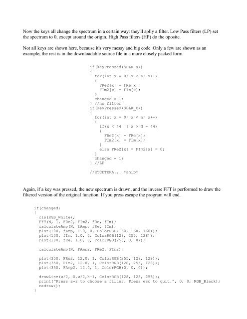
Now the keys all change the spectrum in a certain way: they'll aplly a filter. Low Pass filters (LP) setthe spectrum to 0, except around the origin. High Pass filters (HP) do the oposite.Not all keys are shown here, because it's very messy and big code. Only a few are shown as anexample, the rest is in the downloadable source file in a more closely packed form.if(keyPressed(SDLK_a)){for(int x = 0; x < n; x++){FRe2[x] = FRe[x];FIm2[x] = FIm[x];}changed = 1;} //no filterif(keyPressed(SDLK_b)){for(int x = 0; x < n; x++){if(x < 44 || x > N - 44){FRe2[x] = FRe[x];FIm2[x] = FIm[x];}else FRe2[x] = FIm2[x] = 0;}changed = 1;} //LP//ETCETERA... *snip*Again, if a key was pressed, the new spectrum is drawn, and the inverse FFT is performed to draw thefiltered version of the original function. If you press escape the program will end.if(changed){cls(RGB_White);FFT(N, 1, FRe2, FIm2, fRe, fIm);calculateAmp(N, fAmp, fRe, fIm);plot(100, fAmp, 1.0, 0, ColorRGB(160, 160, 160));plot(100, fIm, 1.0, 0, ColorRGB(128, 255, 128));plot(100, fRe, 1.0, 0, ColorRGB(255, 0, 0));}calculateAmp(N, FAmp2, FRe2, FIm2);plot(350, FRe2, 12.0, 1, ColorRGB(255, 128, 128));plot(350, FIm2, 12.0, 1, ColorRGB(128, 255, 128));plot(350, FAmp2, 12.0, 1, ColorRGB(0, 0, 0));drawLine(w/2, 0,w/2,h-1, ColorRGB(128, 128, 255));print("Press a-z to choose a filter. Press esc to quit.", 0, 0, RGB_Black);redraw();
- Page 1 and 2: Lode's Computer Graphics TutorialFo
- Page 3 and 4: would have a single peak. A spectru
- Page 5 and 6: The spectrum is positive everywhere
- Page 7 and 8: This looks already much more progra
- Page 9 and 10: that remains at fixed position, whi
- Page 11 and 12: It takes 4 arrays as parameters: *g
- Page 13 and 14: FFT, which uses only O(n*logn) oper
- Page 15: FiltersIn the Fourier Domain, it's
- Page 19 and 20: A HP FilterHere, the same is done w
- Page 21 and 22: The main function first loads an im
- Page 23 and 24: And here's the Fast Fourier Transfo
- Page 25 and 26: left corner at xpos,yPos. The shift
- Page 27 and 28: would have only 2 color channels, o
- Page 29 and 30: The sloped lines in the spectrum he
- Page 31 and 32: shown here, the code for all keys i
- Page 33 and 34: }calculateAmp(N, M, fAmp[0][0], fRe
- Page 35 and 36: component back.This is the original
- Page 37 and 38: In the above images, a circular sec
- Page 39 and 40: It looks pretty ugly, because there
- Page 41 and 42: And here's the result of a much thi