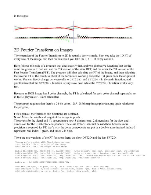
in the signal:2D <strong>Fourier</strong> <strong>Transform</strong> on ImagesThe extension of the <strong>Fourier</strong> <strong>Transform</strong> to 2D is actually pretty simple. First you take the 1D FT ofevery row of the image, and then on this result you take the 1D FT of every column.Here follows the code of a program that does exactly that, and two alternative functions that do thesame are given in it: one will use the 2D version of the slow DFT, and the other the 2D version of theFast <strong>Fourier</strong> <strong>Transform</strong> (FFT). The program will first calculate the FT of the image, and then calculatethe Inverse FT of the result, to check if the formula is working correctly: if it gives back the original itworks. You can freely change between calls to DFT2D() and FFT2D() in the main function, andyou'll notice that the DFT2D() function is very slow now, while the FFT2D() function works veryfast.Because an RGB image has 3 color channels, the FT is calculated for each color channel separately, soin fact 3 greyscale FT's are calculated.The program requires that there's a 24-bit color, 128*128 bitmap image pics/test.png (path relative tothe program).First again all the variables and functions are declared.N and M are the width and height of the image in pixels.The arrays for the signal and it's spectrum are now 3-dimensional: 2 dimensions for the size, and 1dimension for the RGB color components. The class ColorRGB can't be used here because moreprecision is required for FT, that's why the color components are put in a double array instead; index 0represents red, index 1 green, and index 2 is blue.There are two versions of the FT functions here, the slow DFT2D and the fast FFT2D.//yeah, we're working with fixed sizes again...const int N = 128; //the width of the imageconst int M = 128; //the height of the imagedouble fRe[N][M][3], fIm[N][M][3], fAmp[N][M][3]; //the signal's real part, imaginary part, and amplitudedouble FRe[N][M][3], FIm[N][M][3], FAmp[N][M][3]; //the FT's real part, imaginary part and amplitudedouble fRe2[N][M][3], fIm2[N][M][3], fAmp2[N][M][3]; //will become the signal again after IDFT of the spectrumdouble FRe2[N][M][3], FIm2[N][M][3], FAmp2[N][M][3]; //filtered spectrumdouble pi = 3.1415926535897932384626433832795;void draw(int xpos, int yPos, int n, int m, double *g, bool shift, bool neg128);void DFT2D(int n, int m, bool inverse, double *gRe, double *gIm, double *GRe, double *GIm);void calculateAmp(int n, int m, double *ga, double *gRe, double *gIm);
The main function first loads an image, and then sets the signal to that image.Next, it draws the image. It draws the real part, the imaginary part (which is 0!), and the amplitude,which looks the same as the real part.Then it calculates the FT of the image, by using the DFT2D function, but you can as well change this toFFT2D instead: it'll go faster then. Then it draws the just calculated spectrum.Finally, it calculates the inverse FT of that spectrum again and draws the result, this is only to check ifthe functions are working correctly: if you get the original image back, they are.int main(int /*argc*/, char */*argv*/[]){screen(N * 3, M * 3, 0, "2D DFT and FFT");}std::vector img;unsigned long dummyw, dummyh;if(loadImage(img, dummyw, dummyh, "pics/test.png")){print("image pics/test.png not found");redraw();sleep();cls();}//set signal to the imagefor(int x = 0; x < N; x++)for(int y = 0; y < M; y++){fRe[x][y][0] = img[N * y + x].r;fRe[x][y][1] = img[N * y + x].g;fRe[x][y][2] = img[N * y + x].b;}//draw the image (real, imaginary and amplitude)calculateAmp(N, M, fAmp[0][0], fRe[0][0], fIm[0][0]);draw(0, 0, N, M, fRe[0][0], 0, 0);draw(N, 0, N, M, fIm[0][0], 0, 0);draw(2 * N, 0, N, M, fAmp[0][0], 0, 0);//calculate and draw the FT of the imageDFT2D(N, M, 0, fRe[0][0], fIm[0][0], FRe[0][0], FIm[0][0]); //Feel free to change this to FFT2DcalculateAmp(N, M, FAmp[0][0], FRe[0][0], FIm[0][0]);draw(0, M, N, M, FRe[0][0], 1, 1);draw(N, M, N, M, FIm[0][0], 1, 1);draw(2 * N, M, N, M, FAmp[0][0], 1, 0);//calculate and draw the image againDFT2D(N, M, 1, FRe[0][0], FIm[0][0], fRe2[0][0], fIm2[0][0]); //Feel free to change this to FFT2DcalculateAmp(N, M, fAmp2[0][0], fRe2[0][0], fIm2[0][0]);draw(0, 2 * M, N, M, fRe2[0][0], 0, 0);draw(N, 2 * M, N, M, fIm2[0][0], 0, 0);draw(2 * N, 2 * M, N, M, fAmp2[0][0], 0, 0);redraw();sleep();return 0;This is the DFT2D function, it's really just the same as the 1D versions of DFT which was explained inan earlier section, only with an extra loop to do the calculation for every row or column, and repeatedtwice (for the columns, and for the rows), and this separately for every color component. The functiontake now two parameters for the dimensions: m and n, because an image is 2D. The parameter inverse
- Page 1 and 2: Lode's Computer Graphics TutorialFo
- Page 3 and 4: would have a single peak. A spectru
- Page 5 and 6: The spectrum is positive everywhere
- Page 7 and 8: This looks already much more progra
- Page 9 and 10: that remains at fixed position, whi
- Page 11 and 12: It takes 4 arrays as parameters: *g
- Page 13 and 14: FFT, which uses only O(n*logn) oper
- Page 15 and 16: FiltersIn the Fourier Domain, it's
- Page 17 and 18: Now the keys all change the spectru
- Page 19: A HP FilterHere, the same is done w
- Page 23 and 24: And here's the Fast Fourier Transfo
- Page 25 and 26: left corner at xpos,yPos. The shift
- Page 27 and 28: would have only 2 color channels, o
- Page 29 and 30: The sloped lines in the spectrum he
- Page 31 and 32: shown here, the code for all keys i
- Page 33 and 34: }calculateAmp(N, M, fAmp[0][0], fRe
- Page 35 and 36: component back.This is the original
- Page 37 and 38: In the above images, a circular sec
- Page 39 and 40: It looks pretty ugly, because there
- Page 41 and 42: And here's the result of a much thi