91430 SPS cover edited - Electronic Fasteners Inc
91430 SPS cover edited - Electronic Fasteners Inc
91430 SPS cover edited - Electronic Fasteners Inc

You also want an ePaper? Increase the reach of your titles
YUMPU automatically turns print PDFs into web optimized ePapers that Google loves.
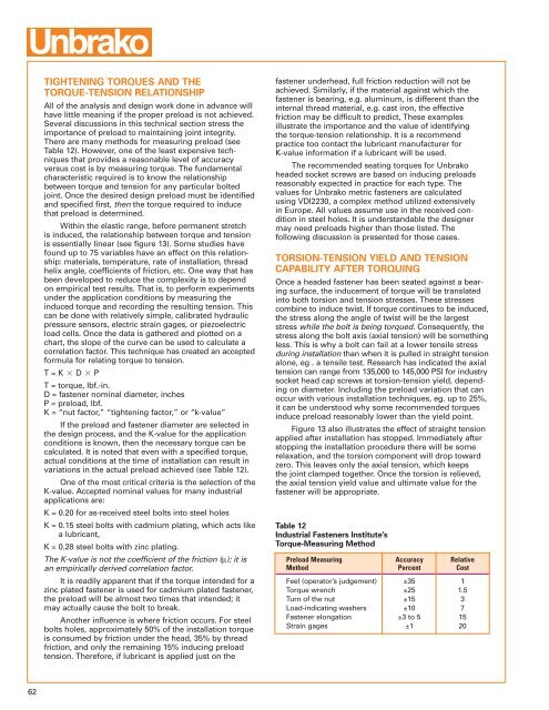
TIGHTENING TORQUES AND THETORQUE-TENSION RELATIONSHIPAll of the analysis and design work done in advance willhave little meaning if the proper preload is not achieved.Several discussions in this technical section stress theimportance of preload to maintaining joint integrity.There are many methods for measuring preload (seeTable 12). However, one of the least expensive techniquesthat provides a reasonable level of accuracyversus cost is by measuring torque. The fundamentalcharacteristic required is to know the relationshipbetween torque and tension for any particular boltedjoint. Once the desired design preload must be identifiedand specified first, then the torque required to inducethat preload is determined.Within the elastic range, before permanent stretchis induced, the relationship between torque and tensionis essentially linear (see figure 13). Some studies havefound up to 75 variables have an effect on this relationship:materials, temperature, rate of installation, threadhelix angle, coefficients of friction, etc. One way that hasbeen developed to reduce the complexity is to dependon empirical test results. That is, to perform experimentsunder the application conditions by measuring theinduced torque and recording the resulting tension. Thiscan be done with relatively simple, calibrated hydraulicpressure sensors, electric strain gages, or piezoelectricload cells. Once the data is gathered and plotted on achart, the slope of the curve can be used to calculate acorrelation factor. This technique has created an acceptedformula for relating torque to tension.T = K D PT = torque, lbf.-in.D = fastener nominal diameter, inchesP = preload, lbf.K = “nut factor,” “tightening factor,” or “k-value”If the preload and fastener diameter are selected inthe design process, and the K-value for the applicationconditions is known, then the necessary torque can becalculated. It is noted that even with a specified torque,actual conditions at the time of installation can result invariations in the actual preload achieved (see Table 12).One of the most critical criteria is the selection of theK-value. Accepted nominal values for many industrialapplications are:K = 0.20 for as-received steel bolts into steel holesK = 0.15 steel bolts with cadmium plating, which acts likea lubricant,K = 0.28 steel bolts with zinc plating.The K-value is not the coefficient of the friction (µ); it isan empirically derived correlation factor.It is readily apparent that if the torque intended for azinc plated fastener is used for cadmium plated fastener,the preload will be almost two times that intended; itmay actually cause the bolt to break.Another influence is where friction occurs. For steelbolts holes, approximately 50% of the installation torqueis consumed by friction under the head, 35% by threadfriction, and only the remaining 15% inducing preloadtension. Therefore, if lubricant is applied just on thefastener underhead, full friction reduction will not beachieved. Similarly, if the material against which thefastener is bearing, e.g. aluminum, is different than theinternal thread material, e.g. cast iron, the effectivefriction may be difficult to predict, These examplesillustrate the importance and the value of identifyingthe torque-tension relationship. It is a recommendpractice too contact the lubricant manufacturer forK-value information if a lubricant will be used.The recommended seating torques for Unbrakoheaded socket screws are based on inducing preloadsreasonably expected in practice for each type. Thevalues for Unbrako metric fasteners are calculatedusing VDI2230, a complex method utilized extensivelyin Europe. All values assume use in the received conditionin steel holes. It is understandable the designermay need preloads higher than those listed. Thefollowing discussion is presented for those cases.TORSION-TENSION YIELD AND TENSIONCAPABILITY AFTER TORQUINGOnce a headed fastener has been seated against a bearingsurface, the inducement of torque will be translatedinto both torsion and tension stresses. These stressescombine to induce twist. If torque continues to be induced,the stress along the angle of twist will be the largeststress while the bolt is being torqued. Consequently, thestress along the bolt axis (axial tension) will be somethingless. This is why a bolt can fail at a lower tensile stressduring installation than when it is pulled in straight tensionalone, eg . a tensile test. Research has indicated the axialtension can range from 135,000 to 145,000 PSI for industrysocket head cap screws at torsion-tension yield, dependingon diameter. <strong>Inc</strong>luding the preload variation that canoccur with various installation techniques, eg. up to 25%,it can be understood why some recommended torquesinduce preload reasonably lower than the yield point.Figure 13 also illustrates the effect of straight tensionapplied after installation has stopped. Immediately afterstopping the installation procedure there will be somerelaxation, and the torsion component will drop towardzero. This leaves only the axial tension, which keepsthe joint clamped together. Once the torsion is relieved,the axial tension yield value and ultimate value for thefastener will be appropriate.Table 12Industrial <strong>Fasteners</strong> Institute’sTorque-Measuring MethodPreload Measuring Accuracy RelativeMethod Percent CostFeel (operator’s judgement) ±35 1Torque wrench ±25 1.5Turn of the nut ±15 3Load-indicating washers ±10 7Fastener elongation ±3 to 5 15Strain gages ±1 2062