54639-01, VSP-VS514SZ-YCAH - Balboa Direct
54639-01, VSP-VS514SZ-YCAH - Balboa Direct
54639-01, VSP-VS514SZ-YCAH - Balboa Direct

You also want an ePaper? Increase the reach of your titles
YUMPU automatically turns print PDFs into web optimized ePapers that Google loves.
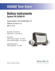
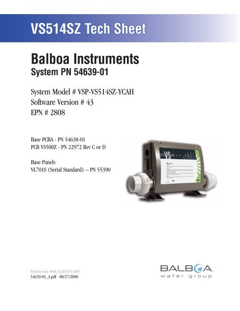
<strong>VS514SZ</strong> Tech Sheet<strong>Balboa</strong> InstrumentsSystem PN <strong>54639</strong>-<strong>01</strong>System Model # <strong>VSP</strong>-<strong>VS514SZ</strong>-<strong>YCAH</strong>Software Version # 43EPN # 2808Base PCBA - PN 54638-<strong>01</strong>PCB VS500Z - PN 22972 Rev C or DBase PanelsVL7<strong>01</strong>S (Serial Standard) – PN 55390Template used: 40600_R.pdf 04/16/2008<strong>54639</strong>-<strong>01</strong>_A.pdf 08/27/2008Page 1<strong>54639</strong>-<strong>01</strong>_A
System Revision HistorySystem PN EPN Date Requested By Changes Made<strong>54639</strong>-<strong>01</strong> 2808 08.27.2008 <strong>Balboa</strong> Software update to version 43.Page 2<strong>54639</strong>-<strong>01</strong>_A
Basic System Features and FunctionsPower Requirements System OutputsSetup 1 (As Manufactured) (Stereo) Optional Devices Additional Options K8J2J1W2W3J1AJ2A1U4K52 3J12J10FUSEJ18J13J60J22J7J8J44BALBOA INSTRUMENTS, INC.VS500ZP/N 22972 REV D2-SPDEXT RLYEXT.RLYAUX. FSEN. ASEN. BVACMADE IN U.S.ACOPYRIGHT 2005Page 3<strong>54639</strong>-<strong>01</strong>_A
CGBasic System Features and FunctionsAny time you change a DIP Switch, other than A1, you must reset PersistentMemory for your new DIP Switch Settings changes to take effect. If you donot reset Persistent Memory, your system may function improperly.To reset Persistent Memory: Power down by disconnecting power source from spa. Put a jumper across J43, covering both pins. (See illustration below) Power up by connecting power source to spa. Wait until “ ” is displayed on your panel. Power down again. Remove jumper from J43 (May also move to cover 1 pin only) Power up again.About Persistent Memory and Time of Day Retention:This system uses memory that doesn’t require a battery to store a variety ofsettings. What we refer to as Persistent Memory stores the filter settings,the set temperature, and the heat mode.Persistent Memory is not used for Time of Day. Only models with aSerial Deluxe panel installed (VS5xxDZ and GS5xxDZ) can display thetime. However, during power loss to the spa, the system will lose thecorrect time, and reset to 12:00 PM when power is restored.Power Up Display SequenceUpon power up, you should see the following on the display: Three numbers in a row, which are the SSID (the System SoftwareID). The third display of these numbers is the Software Version,which should match the version of your system. For example, if thesethree numbers are , that is a VS511SZ at version 38. Displayed next is: “ ” (indicating the system is configured fora heater between 3 and 6 kW) or “ ” (indicating the system isconfigured for a heater effectively* between 1 and 3 kW).“ ” should appear for all VS models running at 240VAC.“ ” should appear for all VS models running at 120VAC, as wellas all GS models. (*A heater which is rated at 4 kW at 240VAC willfunction as a 1 kW heater at 120VAC.) “ ” will appear to signal the start of Priming Mode.At this point, the power up sequence is complete. Refer to the ReferenceCard for the VS or GS System model of your spa for information about howthe spa operates from this point on, including how to adjust the Time ofDay if using a Serial Deluxe style panel.J43E.GNDK6G CF4 FUSE .3A 250VJ23K1W1SWITCHBANKT1AK3K2F2W4E.GNDJ50G CJ6G CSWITCHBANK AF7J17/26S1 TSTS1W7FUSE 20A 250VK8K9J43J46J60 J22J6 J7 J8TSTEXT.RLYJ2AUX. FJ1SEN. AJ47G CW2W3J1AJ2ASEN. BU4J29G CJ13BALBOA INSTRUMENTS, INC. 2-SPDJ44 VS500ZEXT RLYP/N 22972 REV DVACMADE IN U.S.ACOPYRIGHT 2005J43 on VS5xxZ and VS300 Series Main Board Shown.J43 on GS5xxZ Series is located in approximately the same position.K51 2 3J12J20F1J10FUSE 3A 250VJ18J26J90J50LINEBLK ACW1K4K1VS100P/N 22964_B MADE IN U.S.A.© 2006PUMPT0.25A 250V<strong>Balboa</strong>J58G CJ23NEUTRALF2J57HEATEROZONEJ29G CWHT ACK3J9TSTK2K5SWITCHBANK AF4J6 J43S1TSTSWITCHBANK ARSTJ43 on VS100/GS100 Series Main Board Shown.J6J43RSTF5, F3A 250VJ13 J12J7SEN. AJ8SEN. BJ18U4GJ20CJ1Page 4<strong>54639</strong>-<strong>01</strong>_A
Wiring Configuration and DIP SettingsSetup 1 (As Manufactured) (Stereo) CLASS G FUSE 30AJ66J65J11F5WHT ACJ15 J16 J25 J63 J64NEUTRALWHITEBLKJ61JK6J23F4 FUSE .3A 250V2-Spd P1G CJ74W1J73PCBA rev D only.Black jumper required.Do not remove.K1J50 W10W4T1Audio VisualG C1-Spd P2G COzone and Circ Pump must be same voltage.DIP switch A9 must be ON if Circ Pump is installed.F7 FUSE 20A 250J47 J29J17/26W7K9K8J46Circ.PumpG CW2W3J1 J1AOzoneG CK5J2<strong>01</strong>2VLightG CF1J10FUSE 3A 250VK4TORQUERANGEFOR TB1:27-30 IN. LBS.HOTBLACKHOTREDTB1K3K2J2J2AVS5xxS mode2 31U4 J12J18J32 J33 J34 J35J43J100J36<strong>Balboa</strong>J37RED ACHTR2J1<strong>01</strong>HTR15.5 kWHeater rated @ 240V(Approx. 1.25kW @ 120V)W1J1R B W G1-Spd P3F2F30A 480VE.GNDX-P231PN 53681P/N 22909 REV BSWITCHBANK AJ6J60 J22J6 J7 J8S1 TSTEXT.RLYJ7AUX. FSEN. ASEN. BJ44BALBOA INSTRUMENTS, INC.VS500ZP/N 22972 REV DVAC MADE IN U.S.ACOPYRIGHT 20052-SPDEXT RLYJ13WARNING: Main Power to system should be turned OFF BEFORE adjusting DIP switches.WARNING: Persistent Memory (J43) must be RESET to allow new DIP switch settings to take effect. (See Persistent Memory page)SSID #1009343A1, Test Mode OFFA2, See Table 1A7, Exp Board Equip Disabled EnabledA3, J17/26 Pump Disabled EnabledJ43A9, Non-Circ ModeA5, 2-speed P1A10, See Table 1Panel Button AssignmentsPanel Button Positions1=Mode5=Pump 14 1 222=Temp Up6=Unused 6=J17/26 6=Pump 23=Temp Down5 6 73 1 37=Exp 7=Unused Board4=LightPage 5VS51x/VS5xxS/VS5xxDCompatibleJ121 2 3MemoryReset7546Wiring Color Key120 Volt Connections240 Volt ConnectionsBlack AC Jumpers12 Volt ConnectionsRelay Control WiresBoard Connector Key1 Typically Line voltage2 Typically Line voltage for 2-speed pumps3 Neutral (Common)4 GroundNote flat sides in connector<strong>54639</strong>-<strong>01</strong>_A
DIP Switches and Jumpers DefinitionsSSID 100 93 43DIP Switch KeyA1 Test Mode (normally OFF)A2+A10 Control amp draw requirements (See Table 1)A3 “ON” position: J17/26 Enabled for 1-speed Pump only.“OFF” position: J17/26 Disabled.A4 Aux Freeze (must be OFF)A5+A9 Pump 1 speeds and Circ Modes:A5 A9 Circ Mode Pump 1 SpeedOFF OFF Non-circ 2-speedON OFF Circ "acts like Pump 1 low" (filters/polls/ect) 1-speedOFF ON 24 hours with 3°F shut-off 1-speedON ON 24 hours with 3°F shut-off 2-speedBase Model VS503SZ-VS504SZ-<strong>VS514SZ</strong>Table 1 # of Hi-SpeedPumps/BlowerBefore Heat DisabledA2 A10OFF OFF 0ON OFF 1OFF ON 2ON ON 3A6 “ON” position: 50Hz operation“OFF” position: 60Hz operationA7 “ON” position: Expander Board Enabled for Blower or 1-speed Pump.“OFF” position: Expander Board DisabledA8 “ON” position: temperature is displayed in degrees Celsius“OFF” position: temperature is displayed in degrees FahrenheitWhen using a Blower, use X-B expander board. When using a 1-speed Pump 3, use X-P or X-P231, depending on amperage requirements.* Panel with button layout is not compatible.Jumper KeyJ12 Factory set. DO NOT MOVE.Jumper must be on Pins 1 and 2 for VS51xZ/VS52xZ/VS5xxSZ/VS5xxDZ software.Jumper must be on Pins 2 and 3 for VS50xZ software.J43 When jumper is placed on 2 pins during power-up, system will reset persistent memory.Leave on 1 pin only to enable persistent memory feature.WARNING:Setting DIP switches incorrectly may cause abnormal system behavior and/or damage to system components.Refer to Switchbank illustration on Wiring Configuration page for correct settings for this system.Contact <strong>Balboa</strong> if you require additional configuration pages added to this tech sheet.Panel Button PositionsAux Panel Information41 2274Supports 2-button aux panel5 6 731356VX2056When A3 is ONVX205 7When A3 is OFF1=Mode2=Temp Up3=Temp Down4=LightPanel Button Assignments5=Pump 16=Pump 2 (when A3 is ON)7=Exp Board (when A7 is ON)Supports 4-button aux panelVX40S5 6 4 7Page 6<strong>54639</strong>-<strong>01</strong>_A
Expander OptionsK1J6CGK1F5 W12F10A 250VCGJ6J2J4W12X-PPN 53544Used for a 1-speed Pump output. J2J3X-BPN 53310 W1J1R B WX-P231PN 53681P/N 22909 REV BJ6J7W1J1R B WX-P332PN 55137P/N 22909 REV BJ6J7GT30A 480VGT30A 480VX-P231PN 53681 J60 X-P332PN 55137 J13 K1J2J4J6J7J5W12CCGG X-2SP Kit PN 53913 Page 7<strong>54639</strong>-<strong>01</strong>_A
WWOzone ConnectionsOzone Connector Voltage: The VS500Z circuit board is factory configured to deliver a preset voltage (120V or240V) to the on-board ozone connector (J29). See the ratings table on the wiring diagram attached to the coverof the enclosure for the configured voltage. For 240V output W2 connects to Red AC and for 120V output W2connects to White AC.The voltage to the ozone connector can be changed in the field if required. W2 just needs to be set for therequired voltage.WARNING: Changing the voltage of the ozone connector also effects the voltage supplied to the circpump connector (J47). Any equipment controlled by that connector may be damaged if the wrong voltageis selected.<strong>Balboa</strong> Ozone Generator: If the board is set up to operate a 120V ozone generator, the connector on the ozonegenerator is likely to be configured correctly, but should be compared to the illustration below.If a 240V ozone generator is required, be sure the red wire in the ozone cord is positioned in the connector nextto the green ground wire as described below.Note: A special tool is required to remove the pins from the connector body once they are snapped in place.Check with your <strong>Balboa</strong> Account Manager for information on purchasing a pin-removal tool.<strong>Balboa</strong> Ozone connector configuration for 120V 60HzLine - Black conductorUse this slot for the leftover Red conductorCommon - Install the White conductor here for 120V ozoneGround (Green) conductorBG<strong>Balboa</strong> Ozone connector configuration for 240V 60HzLine - Black conductorUse this slot for the leftover White conductorCommon - Install the Red conductor here for 240V ozoneGround (Green) conductorFlat sides of sockets as shownBGFUSE 20A 250VJ46J47J29K8J1Circ.PumpG W B RW2W3J1AK5J2<strong>01</strong>2VLightF1FUSE 3A 250VLine - Black conductorUse this slot for the leftover conductorCommon - Red for 240V or White for 120V ozone (See W2 wire)Ground (Green) conductorW2 wire determines voltageJ10Page 8<strong>54639</strong>-<strong>01</strong>_A