LE-2500 LE-3500 - NeoMore
LE-2500 LE-3500 - NeoMore
LE-2500 LE-3500 - NeoMore

Create successful ePaper yourself
Turn your PDF publications into a flip-book with our unique Google optimized e-Paper software.
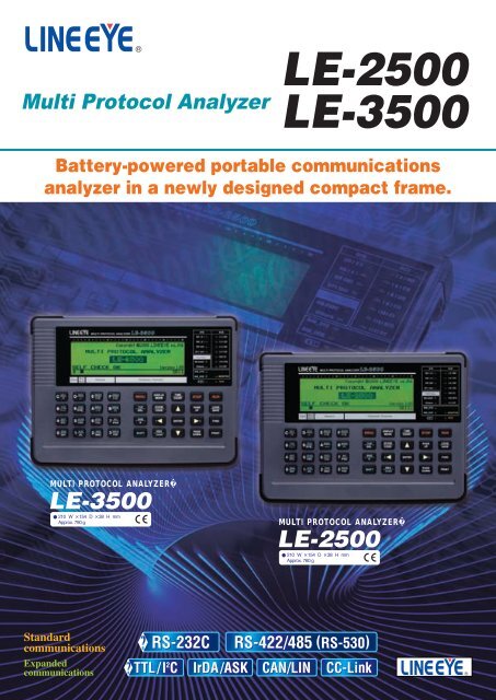
A monitor function to visualize communications data.Supports multi-protocolsTrigger Feature for Catching User-specified EventsThe online monitor featurerecords communications data inthe capture memory and providesan easy-to-understand displayfor the type of protocol, withoutaffecting the communicationsline. As a standard feature,LINE EYE protocol analyzerssupport various communicationsstandards from asynchronousto packet switching systems.Depending on the test, you canselect bit transfer sequence andpolarity, as well as modulationformat from NRZ, NRZI, FMO,FM1 and 4PPM. The featureallows to support effectiveanalysis by omitting SYN codesand using SDLC/HDLC addressfilter.[Data display][Example X.25 protocol translation][Example PPP translation]The trigger feature allows youto specify a communicationsevent as the trigger conditionand have measurement operationsexecuted automatically whenthat condition is satisfied. Up tofour pairs of conditions andoperations can be set, which ishelpful towards identifyingfrequent intermittent faults thatoccurs with communicationssystems. And, the operation ofa trigger condition can bespecified as the condition foranother trigger, making itpossible to analyze complicatedoperations based on sequentialtriggers.[Trigger setup summary display][Example trigger condition setup][Example trigger action setup]Line state <strong>LE</strong>D[Example of connection for online monitoring]Monitor Condition Auto SettingCommunications line state is indicatedin real time using 2-color <strong>LE</strong>DsRecords Time Data with Communication DataLINE EYE protocol analyzersrecord not only communicationsdata but the time (time stamp)of transmissions and receptionsas well as idle time; thereforefailure time and timeout statuscan be checked. It is alsopossible to record the informationof changes in control lines atthe same time.CommunicationsnetworkDCEBeforeconnectionAftermonitorcablecoccectiondmonitor cableRDSD[Example record data selection][Time stamp / idle time display]SDRDDTELINE EYE protocol analyzerscan analyze communicationsdata and automatically setbasic measuring conditions,such as communications speed,character framing, data code,synchronization character,BCC/FCS, etc. This is effectivefor monitoring lines of unknowncommunications conditions.*The auto setting is not accurate withsmall volumes of communicationsdata or data that contains manyerrors.Delay time function added with a voltage measurement featureA feature to measure the voltageof four RS-232C signal lines hasbeen added to the conventionaldelay time function used toanalyze the delay time of controlline changes (e.g., RTS to CTSchanges) at a resolution of 0.1 ms.Statistical Analysis Capabilities[Monitor condition auto setting Ð Search display][Monitor condition auto setting Ð Determination display][Example delay time measurement ]Only for <strong>LE</strong>-<strong>3500</strong>[Timing data display]Statistics can be compiled fortransmission and reception datasets, frames and the number ofestablished trigger events, andsubsequently displayed as a graph(Unit: 1-240 min.). This helps tounderstand communicationstraffic and error frequency fora specific time period.[Graph of statistically analyzed data]BERT function to measure the occurrence rate of communications errors.BERT support enables you tomeasure transmission quality ofcommunications lines by a loopbackor interactive connection.It is possible to measureevaluation parameters (bit errorcount, block error count)conforming to ITU-T G.821Notification, hence enabling biterror rate evaluations and faultpoint identification. Elaboratetest patterns and functions suchas bit error forced interruptare comparable to dedicatedequipment.[Example connection for BERT]Loop-back testTestpatternInteractive testTestpatternCommunicationsnetworkCommunicationsnetworkTestpatternLoopbackpointEvaluation is possible in ASYNCor SYNC mode, by specifyingmeasurement period (continuous,received bits, specified time,repeat) or test pattern.Once started, the results ofmeasured line quality aredisplayed and updated in realtime.[Contents of BERT measurement]Savail Available measurement in seconds 09999999R-Bit Effective bits received 099999999.99E9E-Bit Error bit count099999999.99E9Bit-ER Bit error rate09.99E-91E-Sec Error in seconds09999[BERT setting display][Example BERT measurement]Loss SYNC loss count 09999999R-Blk Effective blocks received 099999999.99E9E-Blk Block error count 099999999.99E9Blk-ER Block error rate 09.99E-91%E.F.S Normal operation rate 0.000100.000%
<strong>LE</strong>-<strong>3500</strong><strong>LE</strong>-<strong>2500</strong>ModelDelay time functionMeasures and displays the interval of change in the interface signal line. (current/min/max/average, resolution: 0. 1ms)Measures and displays the value of voltage amplitude: SD, RD, ER (DTR), and CD (DCD) over RS-232CSignal voltage measuring function(current/min/max, range ±15V, resolution 0.1V).Statistical analysis functionTakes statistics and displays graphs of transmission/reception datacount, number of frames, and satisfied trigger condition count.Not available Specification Measures the logical change of the interface signal in the sampling clock period, and displays its wave.Sampling clock1KHz to 20MHz (14 steps)Sampling memoryMin 2,000Logic analyzer function Trigger conditionTrigger conditions in the ONLINE monitor functions match. Logical status of interface signal or external signal match.Trigger positionBefore, center, afterZoom in/out8 4 2 1 1/2 1/4 1/8 1/16 1/32 1/64Other functionsTime measurement by cursor, signal line exchange, signal status searchSpecificationAt DTE or DCE mode (It is possible to change the pin arrangement ), line quality measurement test such as error rates can be done by loop back test or interactive test. Communication mode Synchronous (SYNC), Asynchronous (ASYNC) Measuring speed 50bps~2. 048Mbps, freely set to four effective digits 50bps~1. 000Mbps, freely set to four effective digitsMeasurement modeContinuous measurememt, specifies the number of receiving bit, specifies the time to measure, repeatedly measurement at the unit of 1 - 1440BERTTest pattern2 6 -12 9 -12 11 -1MARKSPACEALTDBL-ALT3in241in161in81in4(bit error rate test)Error bit insertionInserts 1-bit or 5-bit error in test pattern by key operation.It is able to measure the parameter of the ITU-T advice G.821. Effective received bit (09999999), bit errors (0 to 9999999 to 9. 99E9), bit error rate(0 to 9. 99E-9 to 1),Measurement rangeblock errors (0 to 9999999 to 9. 99E9), block error rate (0 to 9. 99E-9 to 1), Savail(available measurement time: 0 to 9999999sec),loss count (synch loss: 0 to 9999), error duration (0 to 9999999sec), %EFS (normal operation rate: 0. 000 to 100. 000%)Simulation functionMANUAL modeFLOW modeECHO modePOLLING modeBUFFER modePROGRAM modeSpecificationTransmission data entryError data entryLine control modeTransmission driver control(Manual test)(Flow control test)(Echo test)(Multi-polling test)(Buffer transmission test)(Program simulation)Enables transmission/reception test of any given data in DTE or DCE mode (selectable with pin assingnment).Can be registered in 16 types of transmission data tables (Total of 16 K data).A part of transmission data can be registerd as error data such as parity error.Auto Controls transmission timing with RS(RTS), CS(CTS), ER(DTR), CD(DCD) signal lines automatically in 1 msincrements or manual (key operation) can be selected.Auto control turning ON driver only during data transmission or manual mode linking with ER (DTR) or CD (DCD) keyoperation can be selected during simuration of RS-485.Sends the data assinged to operation keys each time a key is pressed, while checking communications status on the display. Can be used together with the trigger function.Simulates the X-on /X-off control data and flow control procedures of RTS/CTS control line. (Sender and receiver selectable).Sends the received data frame by frame (buffer echo), by data (character echo) or by loop back.Simulates multi-polling communications procedures. (Sender and receiver selectable)Reproduces transmission of selected data (SD or RD)Not availablecaptured in memory by monitor function.Creates a simulation program (Max. type: 4, Max steps: 512)using the dedicated commands (36 types) to testNot availablethe communication procedure.SpecificationMeasurement data and condition can be saved in the CF card. And the format of the data/condition can be used in the PC.File typesMeasurement data (.DT), all measurement conditions (.SU), trigger save data (TG SAVEnn.DT), and auto save data (#nnnnnnn.DT)File management functionFile operationsNormal file display, file display by specified type/created date basis, save, load, delete, delete all, and format Max. capacity (*7) 8GB 2GBPrintout function Specified range of measurement data can be continuously printed in format corresponding to the display mode. Displayed images can be printed to make hard copies.LCD Monochrome 240 x 64 dots with backlight Monochrome 240 x 64 dots with no backlightAUX(RS-232C) portMini DIN8 pin connector. Communication speed: 9600bps to 230.4Kbps (6 steps)Print out data, Can be used with PC [<strong>LE</strong>-PC300G], Can be used to upgrade the firmware.USB2.0 port B-connector in device side.Transfer data in full-speedCan be used with PC [<strong>LE</strong>-PC300G], Can be used to upgrade the firmware.External power supply (*8) Provided AC adapterInput: 100 to 240 VAC at 50/60HzBuilt-in batteryNickel hydrogen battery (Model: P-19S), Battery operating time (*9) : About 8 hours, Battery Charging time: About 2.5hoursTemperature rangeIn operation :0to40degrees, In storage : -10 to 50 degreesHumidity range85% (RH) max.StandardCE(class A), EMC(EN61326-1 : 2006)Dimensions210(W)x154(D)x38(H)mmMassAbout 790gAbout 760gAccessoriesMonitor cable for DSUB 25-pin (<strong>LE</strong>-25M1), AUX cable for DSUB 9-pin (<strong>LE</strong>2-8V), external signal I/O cable(<strong>LE</strong>-4TG),AC adapter(3A-181WP09), carrying bag(<strong>LE</strong>B-01), Utility CD, instruction manual and warranty: Standard support. : Supported with option product in [ ].*1: An optional monitor cable (<strong>LE</strong>-259MI) and terminal block (<strong>LE</strong>-25TB) are required in the case of monitoring over RS-232C with a D-sub 9-pin connector or RS-422/485 with a unique terminal arrangement.*2: Tohave the function, optional accessory described in "[ ]" is required.*3: V.35 control signal lines are not supported. *4: Mode in which all data is imported in synch with clock edge. *5: Transmission/reception data,idle time, time stamp, and line status consume 4 bytes of memory at each capture. *6: Correct auto settings are impossible if the amount of communications data is small or communications data includes a largenumber of errors. *7: Operation is not guaranteed with memory cards not specified by LINE EYE. *8: The provided AC adapter (3A-181WP09 with a positive center plug) or the conventional AC adapter (3A-161WP09with a negative center plug) can be used.*9: When LCD back-light is OFF.Order Information<strong>LE</strong>-<strong>3500</strong>/<strong>LE</strong>-<strong>2500</strong> (Comes with Japanese manual.)<strong>LE</strong>-<strong>3500</strong>-E/<strong>LE</strong>-<strong>2500</strong>-E (Comes with English manual.)Standard SetPortable communication analyzer ........................ 1DSUB 25-pin monitor cable (<strong>LE</strong>-25M1) ................ 1DSUB 9-pin AUX cable (<strong>LE</strong>2-8V) ......................... 1External signal I/O cable (<strong>LE</strong>-4TG) ...................... 1AC adapter (3A-181WP09) .................................. 1Carrying bag (<strong>LE</strong>B-01) ........................................ 1Utility CD............................................................ 1Instruction manual............................................... 1Warranty............................................................. 1An easy-totransportcarryingbag is provided.
Cables / Terminal blocks / ConverterOptions for <strong>LE</strong>-<strong>3500</strong> <strong>LE</strong>-<strong>2500</strong>Monitor cable for DSUB 25-pin<strong>LE</strong>-25M1Branch cable for monitoring communicationlines over general DSUB 25-pin.1.5m 0.1mMonitor cable for DSUB 9-pin<strong>LE</strong>-259M1Branch cable for measuring RS-232C overDSUB 9-pin of PC, etc.1.5m 0.2mTerminal block for DSUB 25-pin<strong>LE</strong>-25TBConverts analyzer's RS-485/422 port (DSUB 25-pin specification) to terminal block specification.DB25Terminal block1 12 23 3DB25(Male)*Same as the cable packed with analyzer.DB25(Male) DB25(Female)DB25(Male)DB9(Female)DB9(Male)25 25X.21 Monitor cable<strong>LE</strong>-25Y15Branch cable for measuring X.20/21 overDSUB 15-pin. (Shield type)1.2mRS-449 Monitor cable<strong>LE</strong>-25Y37Branch cable for measuring RS-449 overDSUB 37-pin. (Shield type)1.2mV.35 Monitor cable<strong>LE</strong>-25M34Branch cable for measuring V.35 over M34-pin.1.5mDB15(Male)DB37(Male)M34(Male)DB25(Male)DB15(Female)DB25(Male)DB37(Female)DB25(Male)M34(Female)RS-530 cable<strong>LE</strong>-25S530AUX cable for DPU-414<strong>LE</strong>2-8PAUX cable for DSUB 9-pin<strong>LE</strong>2-8VExternal signal cable<strong>LE</strong>-4TGShield cable for RS-530interface.Cable for connection AUX (RS-232C) port of analyzer and serialport of DPU-414 (printer).¥ Length:1.5mCable for connection AUX (RS-232C)port of an analyzer with PC (DSUB 9-pin DTE specification).¥ Length:2.5m*Same as the cable packed with analyzer.Probe cable for inputing/ outputingexternal signal.*Same as the the cable packed withanalyzer. Memory card Carrying bag AC Adapter8G byte CF cardCF-8GX8G byte compact flash card, the operation of whichhas been confirmed on LINEEYE's Analyzers.Applicable model: <strong>LE</strong>-8200 and <strong>LE</strong>-<strong>3500</strong>Wide input AC adapter3A-181WP09Input: AC100-240V, 50/60HzOutput: DC9V, 2APlug: center*Same as the AC adapter packed with analyzer. Battery pack2G byte CF cardCF-2GX2G byte compact flash card, the operation of whichhas been confirmed on LINEEYE's Analyzers.Applicable model: <strong>LE</strong>-8200, <strong>LE</strong>-<strong>3500</strong>, <strong>LE</strong>-<strong>2500</strong>NiMH battery pack for replacementP-19SRating: 4.8V, 1900mAHApplicable model: <strong>LE</strong>-<strong>3500</strong>, <strong>LE</strong>-<strong>2500</strong>, <strong>LE</strong>-7200, <strong>LE</strong>-3200, <strong>LE</strong>-2200, <strong>LE</strong>-1200*An auxiliary and replacement battery equivalent tothe Analyzer built-in battery.Carrying bag<strong>LE</strong>B-01Bag with pockets for storing and carryingaccessories such as AC adapter, cables, etc.*Same as the carring bag packed with analyzer.Compact thermal PrinterCompact thermal printerDPU-414-31B-EBuilt-in battery, dedicated rollpaper (x1) included.*AC adapter and cable are notprepared. Provide them separately.Handy thermal printer for on-siteprintout of measurements¥ Prints 40 digits per line in normal mode and 80 digits in reduced mode.¥ High-speed printing at 52.5 characters per second.¥ Incorporates eco-friendly NiMH battery.¥ Supports Centronics parallel and RS-232C ports.¥ Dimensions: 160(W)x 170(D)x 67(H)mm¥ Weight: Approx. 690g (including built-in NiMH battery)SAFETYWARNINGDirectiveRoHS CompatibleCompact Thermal Printer SetDPU-414-PAIncludes printer (DPU-414-31B-E),roll paper x1, AC adapter (PW-4007-JU1-E), and printer cable (<strong>LE</strong>2-8P).OptionsAC adapter for DPU-414-31B-EOutput: DC6.5V, 2A(center )PW-4007-JU1-EInput: AC100VPW-4007-EC-EInput: AC230VRoll paper TP-411LTP-411LThermal roll paper forDPU-414-31B-E. 10 rolls per carton.Width: 112mm Length per roll: Approx. 28mBattery pack for DPU-414BP-4005-ESame as NiMH battery built-inDPU-414-31B-E.4.8V, 1100mAhRead the instruction manual provided with the product before use and use the productas explained in that manual. Using the product in ways not guaranteed in the manual,connecting it to systems outside of the specified ranges and remodeling can all causetrouble and damage. LINE EYE CO. LTD. will assume no responsibility whatsoever fortrouble or damage arising because of unauthorized ways of use.LINEEYE CO., LTD.Head Office/Sales OfficeMarufuku Bldg 5F, 39-1 Karahashi Nishihiragaki-cho, Minami-ku, Kyoto, 601-8468PHONE: 81-75-693-0161 FAX:81-75-693-0163MULTI PROTOCOL ANALYZERSister<strong>LE</strong>-8200ProductWDHmm, about1.1kgThe top-level model of battery-powered portable communications analyzer with wide color display.Measurement at Low to Mega Speed upto 4Mbps.A long recording time of communicationslogs on 16G byte CF cards.100 Mbytes capture memory.Logic analyzer function and analog waveform analysis (*).Supports to TTL, I2C, SPI, IrDA, CAN, A compact and lightweight model in B5 sizeLIN, and FlexRay communications. operating continuously for 4 hours.* High-speed analog waveform analysis requires an optional device.• All brand names and product names mentioned in this catalog are trademarks or registered trademarks of theirrespective companies.• Specifications and designs of products listed in this catalog are as of December 2008, and are subject tochange without notice for improvement.• Colors of actual products may differ slightly from that listed due to printing condition.• This catalog may not be reprinted or duplicated, in part or in whole.©2008 by LINEEYE CO., LTD.* LINEEYE CO. LTD. is a venture company founded by electronicequipment development members of the former Sekisui Chemical Co.,Ltd. with investment from the Sekisui Venture Fund. The electronicequipment business of Sekisui Electronic Co. Ltd. was transferred toLINEEYE CO. LTD. in October 2000.QR-00337ER-00094Printed in Japan