VOGT 8150 Variable-Height Keyboard Slide - Rockler.com
VOGT 8150 Variable-Height Keyboard Slide - Rockler.com
VOGT 8150 Variable-Height Keyboard Slide - Rockler.com

Create successful ePaper yourself
Turn your PDF publications into a flip-book with our unique Google optimized e-Paper software.
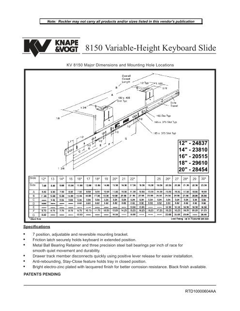
Note: <strong>Rockler</strong> may not carry all products and/or sizes listed in this vendor's publicationKNAPE&<strong>VOGT</strong><strong>8150</strong> <strong>Variable</strong>-<strong>Height</strong> <strong>Keyboard</strong> <strong>Slide</strong>KV <strong>8150</strong> Major Dimensions and Mounting Hole Locations12" - 2483714" - 2381016" - 2051518" - 2961020" - 28454<strong>Slide</strong>12* 13 14* 15 16* 17 18* 19 20* 21 22* 25 26* 27 28* 29 30*SideABCDEFGSpecifications• 7 position, adjustable and reversible mounting bracket.• Friction latch securely holds keyboard in extended position.• Metal Ball Bearing Retainer and three precision steel ball bearings per inch of race forsmooth quiet movement and durability.• Drawer track member disconnects quickly using positive lever release for easier installation.• Anti-rebounding, Stay-Close feature holds tray in closed position.• Bright electro-zinc plated with lacquered finish for better corrosion resistance. Black finish available.PATENTS PENDINGRTD10000604AA
Installation Instructions for:<strong>8150</strong> <strong>Variable</strong>-<strong>Height</strong> <strong>Keyboard</strong> <strong>Slide</strong>For Best Results, Read Instructions First!These instructions show how to install the KV <strong>8150</strong><strong>Keyboard</strong> <strong>Slide</strong>. Please note that improperinstallation may void the Knape & Vogt LifetimeLimited Warranty. To install the slides correctly,follow these instructions, use only KV hardware,and make no modifications. If you have questionsor need additional information, please contact thefactory.Application• Re<strong>com</strong>mended for keyboards.• Mounting brackets adjust from 2-11/32" to3-11/16" in 7/32" increments.Figure 1.• Maximum keyboard tray width not exceeding 24inches.• Cabinet members must be mounted parallelto each other and perpendicular to the worksurface front.• Use #8 x 5/8" Pan Head screws to mountslide to surface and tray. Use #8 x 1/4" threadcutting screws to secure adjustable bracketsat desired height.• Consult factory for advice on unusualapplications.InstallationStep 1Identification.Figure 2.Unpack the slides and identify the left hand and righthand slides. The mounting plates are welded to theoutside of the (larger) cabinet members. Thekeyboard tray will fit flush against the side of the(smaller) drawer members. See figure 1. The rightangle mounting brackets are packaged with left andright hand slides unattached.Figure 3.
KNAPE&<strong>VOGT</strong>Figure 4.Figure 5.Install Drawer MembersFigure 5.Mount drawer membersthrough slots to sides ofkeyboard tray with #8 x 5/8screws. (do not tighten)Drawer membersare unhanded.Step 2 Separate parts.Press the lever and pull to separate the cabinet anddrawer members as shown in Figure 2.Step 3 Adjust brackets.Set the adjustable brackets to the desired heightas shown in figure 3. The brackets may face eitherinwards or outwards. See diagram on back page forheight dimension.Step 4 Install cabinet members.Mount the cabinet members to the underside of thecase as shown in figure 4. Refer to drawing on backcover for mounting hole dimensions. Hole locationvaries dependent on whether the brackets faceinwards or outwards. Fasten screws only throughthe front slotted holes. Additional screws must beadded through the other holes after final adjustment.NOTE: The center slotted holes are for front-to-backadjustment. The other slotted holes are for side-tosideadjustment.Step 5 Install drawer members.Mount the drawer members to the side of thekeyboard tray as shown in figure 5. Refer to drawingon front cover for mounting hole dimensions. Fastenscrews only through the slotted holes. Additionalscrews must be added through the round holes afterfinal adjustment.Step 6 Assembly.First, check that the ball retainers are held in theforward position. Insert the drawer members into thecabinet members as shown in figure 6. Close thedrawer <strong>com</strong>pletely. The force to close the drawermay be more than normal the last few inches,as the ball bearings must slip into the correct synchronousposition.Step 7 Check and adjust installation.Open the drawer and check for proper operation.Make adjustments as needed. Then installadditional screws in the round holes. Securelytighten all screws.Figure 6.
Major Dimensions, Mounting Hole Locations and Adjustable Bracket Settings.Limited Lifetime WarrantyKnape & Vogt Manufacturing Company guaranteesits drawer slides and builder’s hardware productsagainst failure or defects for so long as the purchaseror end user owns them. This warranty is void if anydamage to the product is due to misuse, abuse,neglect, accident, improper installation or any usescontrary to the instructions ac<strong>com</strong>panying the product.This warranty covers the cost of the defectivepart and not the cost of removal, installation or otherincidental charges. The foregoing are the purchaser’sexclusive remedies. Knape & Vogt ManufacturingCompany assumes no liability for special or consequentialdamages.Replacement product may be obtained by returningthe product, transportation charges prepaid, togetherwith a receipt of purchase or other documentsacknowledging the sale of the product, addressed tothe Knape & Vogt Manufacturing Company,Attention: Customer Services Department.The warranty set forth above is in lieu of any otherwarranties, express or implied, including warrantiesor merchantability and fitness for use.®KNAPE&<strong>VOGT</strong>2700 Oak Industrial Drive NEGrand Rapids, Michigan 49505 USAPhone: 616-459-3311Fax: 616-459-3290Telex: 22-6317© 1993, Knape & Vogt300700 rev 5/99