EM-A-BAC-IP-120 - Lutron
EM-A-BAC-IP-120 - Lutron
EM-A-BAC-IP-120 - Lutron

You also want an ePaper? Increase the reach of your titles
YUMPU automatically turns print PDFs into web optimized ePapers that Google loves.
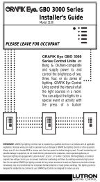
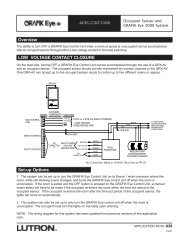
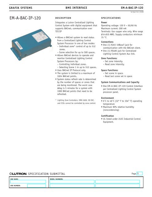
GRAFIK SYST<strong>EM</strong>S BMS INTERFACE <strong>EM</strong>-A-<strong>BAC</strong>-<strong>IP</strong>-<strong>120</strong>DIMENSIONS• 6.5 lbs. (2.95 Kg)• All dimensions are shown in inches and mm• Leave at least 6” clearance on the bottom and right hand side of the enclosure to access the plugin ports, theprogramming button and the status/operation LEDs.rev bac-2-2a 1.10.061.05”(27 mm)6.10”(155 mm)4.0”(102 mm)KNOCKOUT FOR HIGH VOLTAGEWIRING 0.865”(22mm)3.30”(84 mm)12.5”(317 mm)11.75”(298 mm)FRONT VIEW (COVER R<strong>EM</strong>OVED)RIGHT SIDE VIEW<strong>Lutron</strong> Protocol Aux.LinkBOTTOM SIDE VIEW<strong>BAC</strong>net <strong>IP</strong> Connection andDiagnostics® SPECIFICATION SUBMITTALPageJOB NAME:MODEL NUMBERS:JOB NUMBER:
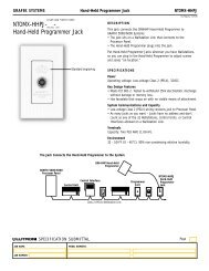
GRAFIK SYST<strong>EM</strong>S BMS INTERFACE <strong>EM</strong>-A-<strong>BAC</strong>-<strong>IP</strong>-<strong>120</strong>WIRINGrev bac-2-3a 1.10.06Power should be wired to the terminal blocks in the unit through the knockout at the top of the can. Use copper wire only. Wire range#14-#10 AWG. Supply conductors rated minimum 75 ˚C. Torque terminals to 5 lb. in (0.7 N-m). DO NOT TOUCH EXPOSED CIRCUITRY ONLOW VOLTAGE SIDE.HIGH VOLTAGE WIRING#14 (2.0mm 2 ) - #10 AWG (4.0mm 2 )Earth GroundNeutralLine <strong>120</strong> V ~ 50/60 HzLOW VOLTAGE AREASTATIC SENSITIVETo Centralized Lighting ControlSystem PanelAux. LinkTo <strong>BAC</strong>net <strong>IP</strong>RJ45 Category 5 cable® SPECIFICATION SUBMITTALPageJOB NAME:MODEL NUMBERS:JOB NUMBER:
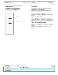
GRAFIK SYST<strong>EM</strong>S BMS INTERFACE <strong>EM</strong>-A-<strong>BAC</strong>-<strong>IP</strong>-<strong>120</strong>rev bac-2-4a 1.10.06OPERATION AND STATUSPower & Communication StatusThe device provides power and communication status information using the LEDs visible on the BOTTOM SIDE of the enclosure.<strong>BAC</strong>net <strong>IP</strong> Link Rx/TxEthernet Link OKPower OKNot UsedFunctional Status and Service ButtonThe device provides functional status indication using the LEDs visible on the RIGHT SIDE of the enclosure.The service button is used to set the <strong>IP</strong> address of the device.Device RunningConfiguration ErrorService Button(used to set address)Communication ErrorSystem ErrorNode OfflineNot Used® SPECIFICATION SUBMITTALPageJOB NAME:MODEL NUMBERS:JOB NUMBER:
GRAFIK SYST<strong>EM</strong>SBMS INTERFACE<strong>EM</strong>-A-<strong>BAC</strong>-<strong>IP</strong>-<strong>120</strong><strong>BAC</strong>NET PROTOCOL IMPL<strong>EM</strong>ENTATION CONFORMANCE STAT<strong>EM</strong>ENT (PICS)rev bac-2-5a 1.10.06Date: 23 June 2003Vendor Name: <strong>Lutron</strong> Electronics Co., Inc.Product Name: Centralized Lighting Control System <strong>BAC</strong>net IntegratorProduct Model Number: <strong>EM</strong>-A-<strong>BAC</strong>-<strong>IP</strong>-<strong>120</strong>Applications Software Version: V4.10c (E) Firmware Revision: V141c (K) <strong>BAC</strong>net Protocol Revision: 1.1Product Description:The <strong>EM</strong>-A-<strong>BAC</strong>-<strong>IP</strong>-<strong>120</strong> is a server that is an interface between a <strong>BAC</strong>net Building Automation System and the <strong>Lutron</strong> GRAFIK CentralizedLighting Control System. The <strong>EM</strong>-A-<strong>BAC</strong>-<strong>IP</strong>-<strong>120</strong> exports a single <strong>BAC</strong>net device with objects that retrieve the status and perform actionsthrough the Centralized Lighting Control System. The <strong>EM</strong>-A-<strong>BAC</strong>-<strong>IP</strong>-<strong>120</strong> can interface with either the zones or the spaces defined in aGRAFIK Centralized Lighting Control System. Both zone control and space control are not possible through the same device. If configuredto interface with zones on the GRAFIK Centralized Lighting Control System, the interface is able to retrieve the relay status and currentintensity and set a desired intensity for each zone in the system. If configured to interface with spaces on the GRAFIK CentralizedLighting Control System, the interface is able to retrieve the last scene set in the space. The space is controlled by selecting a desiredscene.<strong>BAC</strong>net Interoperability Building Blocks Supported (Annex K):K.1.1 BIBB - Data Sharing - ReadProperty-BK.1.8 BIBB - Data Sharing - WriteProperty-BK.5.2 BIBB - Device Management - Dynamic Device Binding-B(DS-RP-B)(DS-WP-B)(DM-DDB-B)<strong>BAC</strong>net Standardized Device Profile (Annex L):<strong>BAC</strong>net Smart Sensor (B-SS)<strong>BAC</strong>net Smart Actuator (B-SA)Segmentation Capability:Segmented requests supported? No Window Size n/aSegmented responses suppored? No Window Size n/aNon-Standard Application Services:The <strong>EM</strong>-A-<strong>BAC</strong>-<strong>IP</strong>-<strong>120</strong> does not support non-standard application services.Standard Object Types Supported:DeviceAnalog Input/OutputBinary Input/OutputMultistate OutputBinary VariableAnalog VariableData Link Layer Options:<strong>BAC</strong>net Ethernet, (Annex J)Device Address Binding:Is static device binding supported?NoIf this product is a communication gateway, describe the types of non-<strong>BAC</strong>net equipment/network(s) that the gateway supports:The <strong>EM</strong>-A-<strong>BAC</strong>-<strong>IP</strong>-<strong>120</strong> is a communication gateway between the <strong>BAC</strong>net protocol and the <strong>Lutron</strong> Centralized Lighting Control Systemcommunication protocol.® SPECIFICATION SUBMITTALPageJOB NAME:MODEL NUMBERS:JOB NUMBER:
GRAFIK SYST<strong>EM</strong>S<strong>BAC</strong>NET OBJECTSBMS INTERFACE<strong>EM</strong>-A-<strong>BAC</strong>-<strong>IP</strong>-<strong>120</strong>rev bac-2-5a 1.10.06The following tables list the <strong>BAC</strong>net objects available through this interface. Refer to the User Guide for a complete description of eachobject listed below. The names of the objects are configurable.Space Machine Interface*Analog Input[1..512]Analog Output[1..512]Binary Input[1..512]Binary Output[1..512]Multistate Output[1..512]Analog Output[513..1024]Binary Value[1..512]Analog Value[1..512]Last system scene selectedDesired scene for spaceReserved for expansion***Reserved for expansion***Reserved for expansion***Reserved for expansion***Reserved for expansion***Reserved for expansion***Zone Machine Interface**Analog Input[1..512] Current zone intensity (%)Analog Output[1..512] Desired zone intensit (%)Binary Input[1..512] Reserved for expansion***Binary Output[1..512] Reserved for expansion***Multistate Output[1..512] Reserved for expansion***Analog Output[513..1024] Reserved for expansion***Binary Value[1..512] Reserved for expansion***Analog Value[1..512] Reserved for expansion**** <strong>BAC</strong>net object ID 1 corresponds to System Space 0, object ID 2 corresponds to System Space 1 and so on.** <strong>BAC</strong>net object ID 1 corresponds to System Zone 0, object ID 2 corresponds to System Zone 1 and so on.*** These objects are reserved by <strong>Lutron</strong> for future modifications and customization of the system.® SPECIFICATION SUBMITTALPageJOB NAME:MODEL NUMBERS:JOB NUMBER: