WACC-01 Flow Controls & Accessories - Watts Fluid Air
WACC-01 Flow Controls & Accessories - Watts Fluid Air
WACC-01 Flow Controls & Accessories - Watts Fluid Air

Create successful ePaper yourself
Turn your PDF publications into a flip-book with our unique Google optimized e-Paper software.
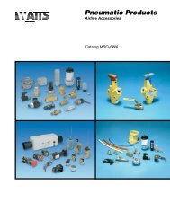
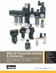
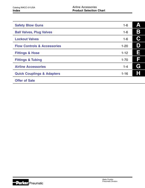
Catalog <strong>WACC</strong>-<strong>01</strong>/USAIndex<strong>Air</strong>line <strong>Accessories</strong>Product Selection ChartSafety Blow Guns 1-6Ball Valves, Plug Valves 1-6Lockout Valves 1-6<strong>Flow</strong> <strong>Controls</strong> & <strong>Accessories</strong> 1-20Fittings & Hose 1-12Fittings & Tubing 1-70<strong>Air</strong>line <strong>Accessories</strong> 1-4Quick Couplings & Adapters 1-16Offer of SaleABCDEFGHPneumatic<strong>Watts</strong> <strong>Fluid</strong><strong>Air</strong>Pneumatic Division
Pneumatic<strong>Flow</strong> <strong>Controls</strong>& <strong>Accessories</strong>Section DD<strong>Flow</strong> Control Valves“SPF” Series ..........................................................2“337” Series ...........................................................3“3250” Series ..................................................... 4-5Right Angle Series ............................................. 6-9Needle Valves“SPN” Series ........................................................10“338” Series .........................................................11“SPC” Series Check Valve ...................................12Pneumatic“339” & “3047” Series Check Valve ..................... 13“EM” Series Exhaust Mufflers .............................. 14Breather Vents ..................................................... 15“ES” Series Silencer............................................. 15ASN <strong>Air</strong> Line Silencer .......................................... 16Muffler-Reclassifier ECS ...................................... 17Automatic Drip Leg Drain .....................................18Relief Valves ........................................................ 18Quick Exhaust & Shuttle Valves .................... 19-21<strong>Watts</strong> <strong>Fluid</strong><strong>Air</strong>Pneumatic Division
Catalog <strong>WACC</strong>-<strong>01</strong>/USA<strong>Flow</strong> Control Valves<strong>Flow</strong> <strong>Controls</strong> & <strong>Accessories</strong>“SPF” Series – 1/8" to 1/2" PortsComponent MaterialsBody Material: BrassNeedle: Stainless SteelBall Check: Stainless SteelCheck Retainer: AcetalNeedle Seals: Nitrile (Standard),Fluorocarbon (Optional)Knob: AluminumDECFB(Open)A(Both Ends)General InformationThe “SPF” Series <strong>Flow</strong> Control Valves meter flow ofair or oil in one direction and allow free flow in thereverse direction.“SPF” Series valves are manufactured with a two stepneedle. Fine metering is accomplished over the initialadjustment turns and nominal metering is providedover the remaining turns. Once the desired flow isselected, a set screw can be tightened to maintain thesetting.These valves are available with NPTF ports in 1/8",1/4", 3/8", and 1/2" sizes.Valve SpecificationsMaximum Operating Pressure2000 PSI Non-ShockCracking pressure for return check poppet –5 PSI NominalOperating TemperatureStandard: 0° to 140° F*-40° to 140° F (Hydraulic service)Extended Temperature: 0° to 400°F** Ambient temperatures below freezing require moisture-free air.Ambient temperatures below freezing and above 180° requirelubricants especially selected for suitability at thesetemperatures. Pneumatic valves should be used with filteredand lubricated air.Model Selection and DimensionsModelNumberA Port Size B C D E FSPF200B 1/8-27 NPTF 1.50 1.75 .625 1.06 .75SPF400B 1/4-18 NPTF 1.80 2.38 .812 1.41 .81SPF600B 3/8-18 NPTF 2.25 2.75 1.000 1.75 1.00SPF800B 1/2-14 NPTF 2.72 3.19 1.250 2.06 1.19For units with Fluorocarbon seals, add suffix “V”. Example: SPF200BVPerformance Data - <strong>Flow</strong>Controlled <strong>Flow</strong>Free <strong>Flow</strong>Needle Full Open/Check ClosedNeedle Full OpenModel <strong>Flow</strong> - SCFM Effective <strong>Flow</strong> - SCFM EffectiveNumber @ 100 PSI C v Area @ 100 PSI C v AreaFull DP Sq. Inches Full DP Sq. InchesSPF200B 8.8 .16 .006 25.4 .46 .<strong>01</strong>8SPF400B 19.3 .35 .<strong>01</strong>3 55.2 1.00 .038SPF600B 33.1 .60 .023 99.3 1.80 .070SPF800B 55.2 1.00 .038 138.0 2.50 .096Pneumatic2 <strong>Watts</strong> <strong>Fluid</strong><strong>Air</strong>Pneumatic Division
Catalog <strong>WACC</strong>-<strong>01</strong>/USAMicrometer <strong>Flow</strong> Control Valves<strong>Flow</strong> <strong>Controls</strong> & <strong>Accessories</strong>“337” Series – 1/8" to 3/4" PortsBody Material: BrassNeedle: Stainless SteelCheck Seal: UrethaneNeedle Seals: Buna N(Fluorocarbon optional –consult factory)CKnob: AluminumSpring: Stainless SteelRetainer: Zinc- Plated SteelSet Screw: SteelModel Selection and Dimensions1BDIA.10 9Component MaterialsAH1 - OPENH2 - CLOSEDAGeneral InformationThe “337” Series <strong>Flow</strong> Control Valves meter flowof air in one direction and allow free flow in thereverse direction.The “337” Series valves are manufactured with a finetapered needle providing precise flow control, even atlow flow rates. The perimeter of the adjustment knobfeatures numerical micrometer position markingsproviding a visual indication of the setting. Once thedesired flow is selected, a set screw can be tightenedto maintain the setting.These valves are available with NPTF ports in 1/8",1/4", 3/8", 1/2", and 3/4" sizes. This series isrecommended for pneumatic service.Valve SpecificationsMaximum Operating Pressure250 PSICracking pressure for return check poppet –1 to 2 PSIGOperating TemperatureStandard: 0° to 180°F*Extended Temperature: 0° to 300°F* (consult factory)* Ambient temperatures below freezing require moisture-free air.Ambient temperatures below freezing and above 180° requirelubricants especially selected for suitability at these temperatures.Pneumatic valves should be used with filteredand lubricated air.Port <strong>Flow</strong> (SCFM†) Dimensions ServiceSize Model Adj. Free <strong>Flow</strong> A B C H1 H2 Kit1/8" 00337 1000 15 32 9/16" 0.75 1.47 2.03 1.81 00337 800<strong>01</strong>/4" 00337 10<strong>01</strong> 28 75 11/16" 0.75 1.47 2.28 2.03 00337 80<strong>01</strong>3/8" 00337 1002 59 139 7/8" 0.88 2.31 2.84 2.53 00337 80021/2" 00337 1003 126 183 1-3/16" 1.06 3.25 3.62 3.22 00337 80033/4" 00337 1004 140 327 1-3/8" 1.06 3.25 3.72 3.31 00337 8004CD† At 100 PSIG inlet pressure with full pressure drop.Mounting Bracket Model Selectionand DimensionsMountingPortDimensionsBracketSizeModel No. A B C D E F G1/8" 00337 8100 0.66 0.66 0.505 0.75 1.38 1.88 0.221/4" 00337 81<strong>01</strong> 0.75 0.89 0.505 0.75 1.50 2.00 0.223/8" 00337 8102 0.94 1.12 0.630 1.25 1.75 2.31 0.271/2" 00337 8103 1.25 1.62 0.755 1.75 2.06 2.62 0.273/4" 00337 8104 1.44 1.72 0.755 1.75 2.25 2.81 0.27.0478Mounting BracketA11BC Dia.G Dia.(2 Holes)D0 9 11E F0 9* 3/32" maximumpanel thickness*Pneumatic3 <strong>Watts</strong> <strong>Fluid</strong><strong>Air</strong>Pneumatic Division
Catalog <strong>WACC</strong>-<strong>01</strong>/USA (Revised 03/21/05)<strong>Flow</strong> Control Valves<strong>Flow</strong> <strong>Controls</strong> & <strong>Accessories</strong>“3250” Series – 1/8" to 3/4" PortsApplicationThe “3250” Series <strong>Flow</strong> Control Valves are specificallydesigned to accurately meter the flow of air in onedirection and allow free flow in the opposite direction.The “3250” Series <strong>Flow</strong> Control Valves are alsosuitable for low pressure hydraulic service.OperationDEB(Closed)CFULLFLOWFAADJFLOWWhen air is moving in the free flow direction throughthe valve, it forces the poppet off its seat andunrestricted air flow is permitted.When air is moving in the metered direction throughthe valve, air pressure and the force of the poppetspring causes the poppet to close. <strong>Flow</strong> must then bethrough the orifice that is controlled by the meteringscrew. Opening this screw allows more flow; closing it,less flow.Technical SpecificationsBody: BrassPort Size: 1/8", 1/4", 3/8", 1/2", 3/4"Internal Components: Brass, Stainless SteelSeals: Buna NOperating Temperature:Standard: 0°F to 180°FExtended Options: 0°F to 300°FOperating Pressures:<strong>Air</strong>: 400 PSIGHydraulic: 800 PSIGValve will operate mounted in any position. Lock nuton metering screw prevents change in setting duringoperation.<strong>Flow</strong> Rating (SCFM)<strong>Flow</strong> PathValve Port Size1/8" 1/4" 3/8" 1/2" 3/4"Maximum <strong>Flow</strong> inMetered Direction70 130 220 295 420Maximum <strong>Flow</strong> inFree <strong>Flow</strong> Direction60 120 205 346 615Model Selection Information and DimensionsModelNumber03250 <strong>01</strong>19 03250 0219 03250 0319 03250 0419 03250 0519Port SizeNPTF1/8" 1/4" 3/8" 1/2" 3/4"Inches mm Inches mm Inches mm Inches mm Inches mmA 1.75 45 2.33 59 2.66 68 3.11 79 3.56 90B 1.56 40 1.97 50 2.44 62 3.06 78 3.69 94C 0.37 9 .44 11 .56 14 .75 19 .88 22D 0.62 16 .75 19 1.00 25 1.25 32 1.50 38E 0.81 21 1.09 28 1.38 35 1.63 41 2.00 51F .68 17 .94 24 1.19 30 1.38 35 1.75 44Pneumatic4 <strong>Watts</strong> <strong>Fluid</strong><strong>Air</strong>Pneumatic Division
Catalog <strong>WACC</strong>-<strong>01</strong>/USAMiniature Right Angle <strong>Flow</strong> Control<strong>Flow</strong> <strong>Controls</strong> & <strong>Accessories</strong>FCM7<strong>01</strong> & FCM703 SeriesGeneral InformationFCM7<strong>01</strong>HDLCMMiniature right angle flow controls provide meter outcontrol of exhaust air from an air cylinder whileproviding full flow in the reverse direction. The 10-32male thread can be used to mount directly to cylinderports. The inlet ports are available in 5-32 or 1/4"instant tube fittings. The adjustment screw is captiveand discourages tampering.This compact flow control saves space and reducesthe number of fittings involved in making theconnection. Plumbing can be oriented 360° aboutthe cylinder port.HCValve SpecificationsMaximum Operating Pressure145 PSIG (10 bar, 1000 kPa) max.FCM703Component MaterialsDLMTemperature Range*0°F to 140°F (-18°C to 60°C)* Ambient temperatures below freezing require moisture-free air.Ambient temperatures below freezing and above 180° requirelubricants especially selected for suitability at these temperatures.Pneumatic valves should be used with filtered and lubricated air.Body: PolyamideMounting thread: BrassDimensionsMiniature Exhaust <strong>Flow</strong> Control FCM7<strong>01</strong>Composite BodyTube Thread C Hex H H <strong>Flow</strong> Adjusted Free <strong>Flow</strong>Part No. Size Size (mm) Closed Open L M Dia. D <strong>Flow</strong> (SCFM) (SCFM)FCM7<strong>01</strong>-5/32-0 5/32 10-32 6 .925 1.023 .846 .669 .080 5.23 2.90FCM7<strong>01</strong>-5/32-2 5/32 1/8 7 1.000 1.083 .935 .708 .100 8.41 6.32FCM7<strong>01</strong>-4-0 1/4 10-32 6 .925 1.023 .885 .708 .080 9.94 3.86FCM7<strong>01</strong>-4-2 1/4 1/8 7 1.000 1.083 .957 .730 .100 10.56 5.08FCM7<strong>01</strong>-4-4 1/4 1/4 8 1.083 1.180 1.<strong>01</strong>3 .748 .160 18.79 10.79Knobless Miniature Exhaust <strong>Flow</strong> Control FCM703Composite BodyTube Thread C Hex H H <strong>Flow</strong> Adjusted Free <strong>Flow</strong>Part No. Size Size (mm) Closed Open L M Dia. D <strong>Flow</strong> (SCFM) (SCFM)FCM703-5/32-0 5/32 10-32 6 .650 .787 .846 .669 .080 7.43 4.76FCM703-4-2 1/4 1/8 7 .708 .860 .956 .730 .100 12.08 5.86FCM703-4-4 1/4 1/4 8 .826 .964 1.<strong>01</strong>3 .748 .160 19.55 10.89Pneumatic6 <strong>Watts</strong> <strong>Fluid</strong><strong>Air</strong>Pneumatic Division
Catalog <strong>WACC</strong>-<strong>01</strong>/USARight Angle <strong>Flow</strong> Control<strong>Flow</strong> <strong>Controls</strong> & <strong>Accessories</strong>FC7<strong>01</strong>, FC702 & FCS7<strong>01</strong> SeriesFC7<strong>01</strong>FC702FCS7<strong>01</strong>DimensionsApplicationThe Right Angle <strong>Flow</strong> Control is an ideal solution tocylinder speed control where space is at a premium.Costly fittings, connections and piping expenses can beeliminated because the valve can rotate 360°, the pipingalignment can be in any direction.OperationInstall by threading male end directly into cylinder port.The free-flow and metered-flow direction is automaticallypredetermined. Free-flow direction is into cylinder andmetered-flow is out of the cylinder. <strong>Flow</strong> is adjusted withan Allen wrench and locked with nut.FC7<strong>01</strong> Series is available with Prestolok fittings on inletport to accommodate 1/8 – 1/2 tube sizes. This allows forquick connection and eliminates need for separate tubefitting.FC702 Series is available with a threaded inletconnection.FCS7<strong>01</strong> Series is available with a swivel outlet, for usewhere access is restricted.Specification and DescriptionBody: Brass Black Epoxy CoatedBolt Material: BrassPlunger: Brass and AcetalSeals: Buna NTemperature Range: -10°F to 200°F (-23°C to 93°C)Pressure Rating: 145 PSIG (10 bar, 1000 kPa) max.Tube Thread Hex Hex L L Adjusted Free <strong>Flow</strong>Part No. Size Size 1 2 Open Closed N M J <strong>Flow</strong> (SCFM) (SCFM)<strong>Flow</strong> Control with Push-in Connecton FC7<strong>01</strong>FC7<strong>01</strong>-2-0 1/8 10-32 1/16 5/16 1.363 1.167 1.040 0.870 0.393 7.06 6.76FC7<strong>01</strong>-2-2 1/8 1/8 5/16 5/8 2.181 2.000 1.330 0.961 0.679 13.40 11.65FC7<strong>01</strong>-5/32-0 5/32 10-32 1/16 5/16 1.363 1.167 1.067 0.870 0.393 9.12 6.60FC7<strong>01</strong>-5/32-2 5/32 1/8 5/16 5/8 2.181 2.000 1.370 1.000 0.679 16.41 15.60FC7<strong>01</strong>-5/32-4 5/32 1/4 5/16 5/8 2.566 2.318 1.377 1.008 0.679 10.99 3.94FC7<strong>01</strong>-4-2 1/4 1/8 5/16 5/8 2.181 2.000 1.361 0.992 0.679 17.74 14.69FC7<strong>01</strong>-4-4 1/4 1/4 5/16 5/8 2.566 2.318 1.381 1.<strong>01</strong>1 0.679 40.03 34.77FC7<strong>01</strong>-4-6 1/4 3/8 5/16 13/16 3.157 2.696 1.582 1.090 0.984 40.90 34.28FC7<strong>01</strong>-6-4 3/8 1/4 5/16 5/8 2.566 2.318 1.507 1.138 0.679 42.05 37.39FC7<strong>01</strong>-6-6 3/8 3/8 5/16 13/16 3.157 2.696 1.677 1.177 0.984 76.33 32.33FC7<strong>01</strong>-6-8 3/8 1/2 9/16 1 3.858 3.287 1.866 1.276 1.181 99.10 117.21FC7<strong>01</strong>-8-8 1/2 1/2 9/16 1 3.858 3.287 2.024 1.433 1.181 140.85 125.24<strong>Flow</strong> Control with Threaded Connection FC702FC702-2 1/8 1/8 5/16 5/8 2.181 2.000 1.117 0.748 0.679 18.75 15.85FC702-4 1/4 1/4 5/16 5/8 2.566 2.318 1.274 0.905 0.679 42.65 34.69FC702-6 3/8 3/8 5/16 13/16 3.157 2.696 1.535 1.043 0.984 59.66 39.91FC702-8 1/2 1/2 9/16 1 3.858 3.287 1.791 1.200 1.18 124.00 123.76<strong>Flow</strong> Control with Swivel Outlet FCS7<strong>01</strong>FCS7<strong>01</strong>-2-2 1/8 1/8 5/16 5/8 2.181 2.000 1.240 0.620 0.679 5.12 7.15FCS7<strong>01</strong>-5/32-0 5/32 10-32 1/16 5/16 1.363 1.167 0.854 0.4<strong>01</strong> 0.393 5.56 5.34FCS7<strong>01</strong>-5/32-2 5/32 1/8 5/16 5/8 2.181 2.000 1.239 0.618 0.679 9.34 9.03FCS7<strong>01</strong>-5/32-4 5/32 1/4 5/16 5/8 2.566 2.318 1.240 0.620 0.679 11.17 10.18FCS7<strong>01</strong>-4-2 1/4 1/8 5/16 5/8 2.181 2.000 1.318 0.657 0.679 17.39 14.25FCS7<strong>01</strong>-4-4 1/4 1/4 5/16 5/8 2.566 2.318 1.318 0.657 0.679 26.35 27.74FCS7<strong>01</strong>-5-4 5/16 1/4 5/16 5/8 2.566 2.318 1.392 0.696 0.679 39.16 34.61FCS7<strong>01</strong>-6-4 3/8 1/4 5/16 5/8 2.566 2.319 1.535 0.755 0.679 39.08 38.02FCS7<strong>01</strong>-6-6 3/8 3/8 5/16 13/16 3.157 2.696 1.740 0.834 0.984 59.97 41.47FCS7<strong>01</strong>-6-8 3/8 1/2 9/16 1 3.858 3.287 1.619 0.992 1.181 92.50 81.47CDPneumatic7 <strong>Watts</strong> <strong>Fluid</strong><strong>Air</strong>Pneumatic Division
Catalog <strong>WACC</strong>-<strong>01</strong>/USAMiniature Right Angle <strong>Flow</strong> Control<strong>Flow</strong> <strong>Controls</strong> & <strong>Accessories</strong>M5 (10-32) Port3mm Dia.General InformationMiniature right angle flow controls provide meter outcontrol of exhaust air from an air cylinder whileproviding full flow in the reverse direction. TheM5 (10-32) male thread can be used to mountdirectly to cylinder ports. The inlet ports areavailable in M5 (10-32) male or 5/32" instant tubefitting. The adjustment screw is captive anddiscourages tampering.This compact flow control saves space and reducesthe number of fittings involved in making theconnection. Plumbing can be oriented 360°about the cylinder port.ALCKHValve SpecificationsMaximum Operating Pressure145 PSIG (10 bar)Component MaterialsBody: PolyamideMounting thread: BrassOperating Temperature0° to 140°F** Ambient temperatures below freezing require moisture-free air.Ambient temperatures below freezing and above 180° requirelubricants especially selected for suitability at these temperatures.Pneumatic valves should be used with filtered and lubricated air.Model SelectionPortsWrenchMale Female SizeModel NumberM5 M5 5/16" PWRE14557M5 5/32" Tube 5/16" PWRE14457Note: Standard 10-32 fittings will fit the M5 threads on valve body.Dimensions - Inches (mm)A C K H L.43 .16 .28 .67 .79(11) (4) (7,2) (17) (20)<strong>Flow</strong>No of Exhaust InletTurns (Screw Open) (Screw Closed)12 1.8 SCFM 1.8 SCFMPneumatic8 <strong>Watts</strong> <strong>Fluid</strong><strong>Air</strong>Pneumatic Division
Catalog <strong>WACC</strong>-<strong>01</strong>/USAHeavy Duty Right Angle <strong>Flow</strong> Control<strong>Flow</strong> <strong>Controls</strong> & <strong>Accessories</strong>“3251” SeriesApplicationThe Heavy Duty Right Angle <strong>Flow</strong> Control is an idealsolution to cylinder speed control where space is ata premium. Costly fittings, connections and pipingexpenses can be eliminated because the valve canrotate 360°, the piping alignment can be in any direction.The 1/8" model can be rotated after final assembly.CShown withThreaded InletShown with PrestolokInlet FittingBB1Metered <strong>Flow</strong>AOpenFree<strong>Flow</strong>COperationInstall by threading male end directly into cylinderport. The free-flow and metered-flow direction isautomatically predetermined. Free-flow direction isinto cylinder and metered-flow is out of the cylinder.<strong>Flow</strong> is adjusted with an Allen wrench and lockedwith nut.Heavy Duty Right Angle <strong>Flow</strong> Control also availablewith Prestolok fittings on inlet port to accommodate5/32 - 3/8 tube sizes. This allows for quick connectionand eliminates need for separate tube fitting.DSpecification and DescriptionBody: BrassPlunger: Brass and AcetalSeals: Buna NTemperature Range: 0°F to 140°F (–18°C to 60°C)Pressure Rating: 125 PSIG (863 kPa) max.Model Selection Information and DimensionsThread Thread A B C Weight CvModel(NPT) (NPT) Adjusted FreeNumberInches mm Inches mm Inches mm oz. kg.Male Female<strong>Flow</strong> <strong>Flow</strong>03251 <strong>01</strong>25 1/8 1/8 1.63 41 1.18 30 .67 17 2.0 0.9 0.26 0.2003251 0250 1/4 1/4 1.86 47 1.40 36 .91 23 4.5 2.0 0.75 0.6803251 0375 3/8 3/8 2.15 55 1.71 43 1.06 27 7.0 3.2 0.84 0.7203251 0500 1/2 1/2 2.54 65 1.98 53 1.26 32 11.0 5.0 1.64 1.41With Prestolok Thread TubeFittings (NPT) SizeA B 1 C Weight Cv03251 1215 1/8 5/32 1.63 41 1.18 30 .67 17 2.0 0.9 0.19 0.1603251 1225 1/8 1/4 1.63 41 1.18 30 .67 17 2.0 0.9 0.28 0.2203251 2525 1/4 1/4 1.86 47 1.40 36 .91 23 4.5 2.0 0.51 0.4403251 2538 1/4 3/8 1.86 47 1.40 36 .91 23 4.5 2.0 0.62 0.5303251 3838 3/8 3/8 2.15 55 1.71 43 1.06 27 7.0 3.2 0.78 0.65!CAUTION: If it is possible that the ambient temperature may fall below freezing, the medium must be moisture-free to prevent internaldamage or unpredictable behavior.Pneumatic9 <strong>Watts</strong> <strong>Fluid</strong><strong>Air</strong>Pneumatic Division
Catalog <strong>WACC</strong>-<strong>01</strong>/USANeedle Valves<strong>Flow</strong> <strong>Controls</strong> & <strong>Accessories</strong>“SPN” Series – 1/8" to 1/2" PortsGeneral InformationThe “SPN” Series needle valves provide excellentbi-directional speed control for pneumatic andhydraulic applications.ECFB(Open)“SPN” valves are manufactured with a two step needle.Fine metering is accomplished over the initialadjustment turns and nominal metering is providedover the remaining turns. Once the desired flow isselected, a set screw can be tightened to maintainthe setting.DA(Both Ends)These valves are available with NPTF ports in 1/8",1/4", 3/8" and 1/2" sizes.Valve SpecificationsComponent MaterialsBody: BrassNeedle: Stainless SteelNeedle seals: Nitrile (Standard),Fluorocarbon (Optional)Knob: AluminumMaximum Operating Pressure2000 PSI Non-ShockOperating TemperatureStandard: 0° to 140° F*Extended temperature: 0° to 400°F** Ambient temperatures below freezing require moisture-free air.Ambient temperatures below freezing and above 180° requirelubricants especially selected for suitability at these temperatures.Pneumatic valves should be used with filtered and lubricated air.Model Selection and DimensionsModelNumber A Port Size B C D E FSPN200B 1/8-27 NPTF 1.50 1.50 .625 .75 .75SPN400B 1/4-18 NPTF 1.80 2.00 .812 1.00 .81SPN600B 3/8-18 NPTF 2.25 2.25 1.000 1.13 1.00SPN800B 1/2-14 NPTF 2.72 2.62 1.250 1.31 1.19For units with Fluorocarbon seals, add suffix “V”. Example: SPN200BVPerformance DataControlled <strong>Flow</strong>Needle Full OpenModel <strong>Flow</strong> - SCFMAreaNumber @ 100 PSI C v Sq. InchesFull DPSPN200B 8.8 .16 .006SPN400B 19.3 .35 .<strong>01</strong>3SPN600B 33.1 .60 .023SPN800B 55.2 1.00 .038Pneumatic10 <strong>Watts</strong> <strong>Fluid</strong><strong>Air</strong>Pneumatic Division
Catalog <strong>WACC</strong>-<strong>01</strong>/USANeedle Valves<strong>Flow</strong> <strong>Controls</strong> & <strong>Accessories</strong>“338” Series – 1/8" to 3/4" PortsBDIA.General Information“338” Series needle valves bi-directionally meter theflow of air through the valve.This series features a fine tapered needle providingprecise flow of air in both directions. Numericalmicrometer position markings are stamped on theperimeter of the adjustment knob which provide avisual indication of the setting. Once the desired flowis selected, a set screw can be tightened to maintainthe setting.CDO-ring forfriction 110 9H1 - OPENH2 - CLOSEDThese valves are available with NPTF ports in 1/8",1/4", 3/8" 1/2" and 3/4" sizes. This series isrecommended for pneumatic service.ACAComponent MaterialsBody Material: BrassInternal Components: Stainless Steel/BrassSeals: Nitrile (Fluorocarbon optional – consult factory)Valve SpecificationsMaximum Operating Pressure250 PSIG (<strong>Air</strong>)Operating TemperatureStandard: 0° to 180° F*Extended Temperature: 0°F to 300°F*(Consult factory)* Ambient temperatures below freezing require moisture-free air.Ambient temperatures below freezing and above 180° requirelubricants especially selected for suitability at these temperatures.Pneumatic valves should be used with filtered and lubricated air.Model Selection and DimensionsPort Dimensions ServiceSize Model A B C H1 H2 Kit1/8" 00338 1100 9/16" 0.75 1.47 2.03 1.81 00337 800<strong>01</strong>/4" 00338 11<strong>01</strong> 11/16" 0.75 1.47 2.28 2.03 00337 80<strong>01</strong>3/8" 00338 1102 7/8" 0.88 2.31 2.84 2.53 00337 80021/2" 00338 1103 1-3/16" 1.06 3.25 3.62 3.22 00337 80033/4" 00338 1104 1-3/8" 1.06 3.25 3.72 3.31 00337 8004Performance Data – <strong>Flow</strong>Port Model <strong>Flow</strong>Size Number (SCFM†)1/8" 00338 1100 151/4" 00338 11<strong>01</strong> 283/8" 00338 1102 591/2" 00338 1103 1263/4" 00338 1104 140† At 100 PSIG inlet pressure with full pressure drop.Pneumatic11 <strong>Watts</strong> <strong>Fluid</strong><strong>Air</strong>Pneumatic Division
Catalog <strong>WACC</strong>-<strong>01</strong>/USACheck Valves<strong>Flow</strong> <strong>Controls</strong> & <strong>Accessories</strong>“SPC” Series – 1/8" to 1/2" PortsGeneral DescriptionCheck valves provide free flow of air or oil in onedirection and dependable shutoff in the oppositedirection.These valves are available with NPTF ports in 1/8",1/4", 3/8" and 1/2" sizes.DSq.CFree<strong>Flow</strong>Component MaterialsBody: BrassPoppet: Stainless SteelPoppet Seal: Buna (Nitrile)Poppet Retainer: Stainless SteelSpring: Stainless SteelPoppet Style: Soft Seal StandardValve SpecificationsMaximum Operating Pressure2000 PSI Non-ShockOperating Temperature0° to 140° F*-40° to 140° F (Hydraulic service)* Ambient temperatures below freezing require moisture-freeair. Ambient temperatures below freezing and above 180°require lubricants especially selected for suitability at thesetemperatures. Pneumatic valves should be used with filteredand lubricated air.Model Selection and DimensionsModelNumber A Port Size D CSPC200B 1/8-27 NPTF 0.62 2.00SPC400B 1/4-18 NPTF 0.81 2.62SPC600B 3/8-18 NPTF 1.00 2.75SPC800B 1/2-14 NPTF 1.25 3.44Performance Data - <strong>Flow</strong>Model Free <strong>Flow</strong> OrificeNumber Port Size, Inches SCFM* Cv area, in. 2SPC200B 1/8-27 NPTF 29.2 0.53 0.023SPC400B 1/4-18 NPTF 86.1 1.56 0.068SPC600B 3/8-18 NPTF 125.3 2.27 0.099SPC800B 1/2-14 NPTF 282.0 5.11 0.224* At 100 PSI, Full ΔPPneumatic12 <strong>Watts</strong> <strong>Fluid</strong><strong>Air</strong>Pneumatic Division
Catalog <strong>WACC</strong>-<strong>01</strong>/USACheck Valves<strong>Flow</strong> <strong>Controls</strong> & <strong>Accessories</strong>“339” Series, “3047” Series“339” Series – 1/8" to 3/4" Ports“3047” – 1/4" Male PipeC13/16 HexD35/64 FlatsB .22 (6)Dia.AB2.31(59)General Information“339” Series check valves allow free flow in onedirection and provide positive checked (zero flow) inthe reverse direction. These valves are available withNPTF ports in 1/8", 1/4", 3/8", 1/2" & 3/4" sizes. Thisseries is recommended for pneumatic service.Valve SpecificationsMaximum Operating Pressure250 PSIGCracking Pressure: 1 to 2 PSIGOperating TemperatureStandard: 0° to 180° F*Extended Temperature Option: 0°F to 300°F*Component MaterialsBody Material: BrassInternal Components: Brass / Stainless Steel /Zinc- Plated SteelSeals: Urethane (standard),Fluorocarbon (optional – consult factory)Model Selection and DimensionsPort Model <strong>Flow</strong> † Dimensions ServiceSize Number (SCFM) A B Kit1/8" 00339 3000 35 1.22 0.56 00337 800<strong>01</strong>/4" 00339 30<strong>01</strong> 75 1.34 0.69 00337 80<strong>01</strong>3/8" 00339 3002 143 2.00 0.88 00337 80021/2" 00339 3003 162 2.56 1.19 00337 80033/4" 00339 3004 323 2.66 1.38 00337 8004PneumaticGeneral Information“3047” Series check valves allow free flow in onedirection and provide positive checked (zero flow) inthe reverse direction. This valve is available with amale 1/4" NPTF connection and is recommended forpneumatic service.Valve SpecificationsMaximum Operating Pressure250 PSIGCracking Pressure: 1 to 2 PSIGOperating TemperatureStandard: 0° to 180° F** Ambient temperatures below freezing require moisture-free air.Ambient temperatures below freezing and above 180° requirelubricants especially selected for suitability at these temperatures.Pneumatic valves should be used with filtered and lubricated air.Component MaterialsBody Material: BrassInternal Components: Brass/Stainless SteelSeals: NitrileModel SelectionPipe Model <strong>Flow</strong> †Thread Number (SCFM)1/4" 03047 0099 30† At 100 PSIG inlet pressure with full pressure drop.13 <strong>Watts</strong> <strong>Fluid</strong><strong>Air</strong>Pneumatic Division
Catalog <strong>WACC</strong>-<strong>01</strong>/USAMuffler / Filters, Muffler / Speed <strong>Controls</strong><strong>Flow</strong> <strong>Controls</strong> & <strong>Accessories</strong>“EM” Series, Muffler / Speed <strong>Controls</strong>“EM” Series – Sintered Bronze Muffler / FiltersMuffler / filters effectively reduce air exhaust noises toan industry accepted level with minimum flowrestriction. They protect valves, impact wrenches,screw drivers and other air tools by preventing dirt andother foreign matter from entering the system. Noncorrosive.Can be cleaned with many commonsolvents.Maximum Operating Pressure250 PSIG (<strong>Air</strong>)Operating Temperature0° to 300° F*Pipe Thread Model Number Overall Length Hex Size1/8" EM12 1.00 7/16"1/4" EM25 1.32 9/16"3/8" EM37 1.54 11/16"1/2" EM50 1.85 7/8"3/4" EM75 2.29 1-1/6"1" EM100 2.91 1-5/16"1-1/4" EM125 3.25 1-11/16"1-1/2" EM150 3.69 2"Muffler / <strong>Flow</strong> <strong>Controls</strong>Muffler / <strong>Flow</strong> controls provide an acceptable exhaustnoise level and effectively meter exhaust. Installed invalve exhaust ports, they control cylinder pistonspeeds throughout a wide range. The adjusting screwcannot be accidently blown out, can be locked tomaintain setting. Brass and bronze construction.Clean with commonly used solvents.Maximum Operating Pressure250 PSIG (<strong>Air</strong>)Operating Temperature0° to 300° F*Pipe Thread Model Number Overall Length Hex Size1/8" 04502 0002 1.15 9/16"1/4" 04504 0004 1.42 5/8"3/8" 04506 0060 1.49 11/16"1/2" 04508 0080 1.77 7/8"3/4" 04512 0<strong>01</strong>2 1.98 1-1/16"1" 04516 0<strong>01</strong>6 2.15 1-5/16"Pneumatic14 <strong>Watts</strong> <strong>Fluid</strong><strong>Air</strong>Pneumatic Division
Catalog <strong>WACC</strong>-<strong>01</strong>/USABreather Vents, Silencers<strong>Flow</strong> <strong>Controls</strong> & <strong>Accessories</strong>Breather Vents & “ES” SeriesBreather VentsNOTE: Breather vents should notbe used as exhaust mufflers.These low silhouette versions of the muffler/filter areuseful where space is a problem and/or to preventcontamination. Use for vacuum relief or pressureequalization in gear boxes, oil tanks, reservoirs, etc.Non-corrosive.Maximum Operating Pressure250 PSIG (<strong>Air</strong>)Operating Temperature0° to 300° F** Ambient temperatures below freezing require moisture-free air.Ambient temperatures below freezing and above 180° requirelubricants especially selected for suitability at these temperatures.Pneumatic valves should be used with filtered and lubricated air.Pipe Thread Model Number Overall Length Hex Size1/8" 04702 0002 0.44 7/16"1/4" 04704 0004 0.63 9/16"3/8" 04706 0006 0.75 11/16"1/2" 04708 0008 0.88 7/8"3/4" 04712 0<strong>01</strong>2 1.00 1-1/6"1" 04716 0<strong>01</strong>6 1.31 1-5/16"1-1/4" 04720 0020 1.41 1-11/16"1-1/2" 04724 0024 1.50 2"CD“ES” Series – SilencerEDCABThe silencer is designed to give superior performancein noise control with a minimum effect on air efficiency.“Trimline” design allows location in the tightest placeswithout extra plumbing and fittings. Fits directly into theexhaust port of more than 90% of present commercialvalves. Slotted body permits rapid discharge of airwithout undesirable back pressure. Unique nylonscreen element resists dirt buildup or clogging.Maximum Operating Pressure250 PSIG (<strong>Air</strong>)Operating TemperatureNPT0° to 300° F*Pipe ThreadModel NumbersDimensions<strong>Flow</strong> SCFM @ 100 PSIG InletNPTF BSPT (R) A B C D E1/8" ES12MB ESB12MB 115 2.31 0.62 0.31 0.68 5/8"1/4" ES25MB ESB25MB 129 2.41 0.88 0.50 0.97 7/8"3/8" ES37MB ESB37MB 219 3.06 1.25 0.50 1.38 1-1/4"1/2" ES50MB ESB50MB 549 3.19 1.25 0.64 1.38 1-1/4"3/4" ES75MB ESB75MB 893 4.69 1.50 0.66 1.62 1-1/2"1" ES100MB ESB100MB 1,<strong>01</strong>3 4.69 1.50 0.81 1.62 1-1/2"1-1/4" ES125MB ESB125MB 1,486 5.69 2.88 1.25 — —1-1/2" ES150MB ESB150MB 1,580 5.69 2.88 1.25 — —Pneumatic15 <strong>Watts</strong> <strong>Fluid</strong><strong>Air</strong>Pneumatic Division
Catalog <strong>WACC</strong>-<strong>01</strong>/USA<strong>Air</strong> Line Silencer – Plastic<strong>Flow</strong> <strong>Controls</strong> & <strong>Accessories</strong>ASN Series – M5, 1/8", 1/4", 3/8" & 1/2"ABFeatures• Compact• Lightweight• Easy to install• Excellent noise reduction• Protects components fromcontamination• NPT & BSPT threads availableApplicationThe plastic silencer is designed to give excellent noisereduction with a minimum effect on air efficiency.The “Trimline” design allows for locating the silencerin the tightest places without extra plumbing or fittings.Fits directly into the exhaust port of most commercialvalves. Open surface area of element allows for rapiddischarge of air without undesirable back pressure.PartMaximum <strong>Flow</strong>Sound PressureThread Number A B Level (dBA)(SCFM)Size(mm) (mm)NPT BSPT100 PSIG Inlet 20 PSIG 100 PSIGInlet InletM5 AS-5.43 .3215 69 79(11) (8)1/8" ASN-6 AS-61/4" ASN-8 AS-83/8" ASN-10 AS-1<strong>01</strong>/2" ASN-15 AS-151.57 .63(40) (16)2.56 .83(65) (21)3.35 .98(85) (25)3.74 1.18(95) (30)51 69 81124 67 84247 83 98370 69 96SpecificationsBody:Acetal (Plastic)Element:PolyethylenePressure Rating:0 to 150 PSIG(0 to 10 bar, 0 to 1034 kPa)Temperature Rating:14°F to 140°F (-10°C to 60°C)Pneumatic16 <strong>Watts</strong> <strong>Fluid</strong><strong>Air</strong>Pneumatic Division
Catalog <strong>WACC</strong>-<strong>01</strong>/USA<strong>Air</strong> Line Muffler – Reclassifier<strong>Flow</strong> <strong>Controls</strong> & <strong>Accessories</strong>ECS Series – 1/2" & 1"Performance Characteristics12<strong>01</strong>008060dBa<strong>Flow</strong> vs. Noise Level■4020❍ 1" Open Pipe ❏ 1/2" Open Pipe● ECS5 ■ ECS300 10 20 30 40 50 60 70 80 90 100SCFMFeatures❏10 20 30 40dm 3 /sn❍●Pneumatic.69.55.41.28.14bar10PSID86ADimensions:Model A B CECS3 5.30 1/2" 2.57(135 mm) NPT (65 mm)ECS5 7.30 1" 2.57(185mm) NPT (65mm)<strong>Flow</strong> vs. Back Pressure■4■2ECS3 Back Pressure● ECS5 Back Pressure00 10 20 30 40 50 60 70 80 90 100SCFMCB10 20 30 40dm 3 /snThe ECS (Muffler-Reclassifier) eliminates unwanted oilmist and reduces exhaust noise from pneumaticvalves, cylinders and air motors.• 99.97% Oil removal efficiencies• 25 dBA Noise attenuation• 1/2" NPT and 1" NPT• Disposable units• Continuous or plugged drain option• Metal retained construction• Fast exhaust timeImprove Overall Plant EnvironmentExhaust oil mist and noise pollution have a directimpact on worker productivity.Oil aerosol mist from lubricators and compressors ispervasive and enters the industrial plant environmentthrough the exhaust ports of valves, cylinders and airmotors. This rapidly expanding exhaust also producessudden and excessive noise.The ECS (Muffler-Reclassifier) is 99.97% efficient atremoving the oil aerosols. The ECS also acts as asilencer to lower the dBA levels below O.S.H.A.requirements.The result is a cleaner, quieter environment whichequates to greater work productivity and safety.●OperationCompressor oils and lubricating oils are exhaustedfrom valves, cylinders and air motors into the ECS.Oil aerosols are “coalesced” into larger droplets andgravity pulls them into the attached drain sump.The sump can then be drained manually or by usinga 1/4" ID plastic tube drain. The air flowing into theECS is also muffled or silenced as it enters the insideof the ECS and passes through the filter media intothe atmosphere.Proven TechnologyThe ECS units are constructed from the samematerials that go into our oil removal coalescing filterelements.The seamless design insures media uniformity andstrength. This proven technology provides highcoalescing efficiency with low pressure drop.The filter media is supported by cylindrical perforatedsteel retainers both inside and out. These retainers,fully plated for excellent corrosion resistance, give theECS units high rupture strength in either flow direction.These filters can also be used as high efficiency inlet orbypass filters for vacuum pumps, or breather elementsto protect the air above critical process liquids.ECS3 / ECS5The ECS solves two problems inherent in compressedair exhaust from valves, cylinders and air motors - oilmist removal and noise abatement.The ECS will improve your industrial plant environment,thereby improving worker productivity.SpecificationsMaximum Operating Temperature125°F (52°C)Maximum Line Pressure100 PSIG (690 kPa)Ordering InformationECS 3 ASize3. 1/2 inch5. 1 InchEngineeringLevelA. Current17 <strong>Watts</strong> <strong>Fluid</strong><strong>Air</strong>Pneumatic DivisionCD
Catalog <strong>WACC</strong>-<strong>01</strong>/USAAutomatic Drip Leg Drain, Relief Valve<strong>Flow</strong> <strong>Controls</strong> & <strong>Accessories</strong>Features & OperationAutomatic Drip Leg DrainRelief ValveABFCFeatures• Auto drain ported 1/8" to pipe away liquid.• Drain has manual override.• Easily serviced without tool.• 10-250 PSIG range.• Compact size.SpecificationsHousing & Cap:AluminumPort Threads:1/4" - 1/2" Top1/8" DrainPressure & Temperature RatingsMetal Bowl:0 to 250 PSIG (0 to 1725 kPa)32°F to 175°F (0°C to 80°C)Seals:Buna NOrdering InformationConsists of Drip Leg Drain Housing WITH Auto Drain.Model No. Size06D1NA 1/4"06D3NA 1/2"A B C2.50 2.37 .8764 mm 60 mm 22 mmBAAB.75 Hex 2.0<strong>01</strong>9 mm 50.8 mmFeatures• Large relief capacity in a compact size.• Lightweight aluminum construction with resilient seat.ApplicationThe RV<strong>01</strong>A1N Pop Off Relief Valve is designed toprotect against excessive pressure buildup in apneumatic circuit or system.OperationWith the relief valve mounted in a reservoir or system,the force of system pressure at (A) is offset by theforce of spring (C) acting on poppet seat (B). Atpressures lower than the setting, the poppet seat (B) isheld against the body at (A) effecting a seal.When pressure rises above the set point, the force ofthe pressure lifts the poppet seat (B) off the body at (A)allowing the excess pressure to vent to atmosphere at(F). When the excess pressure has been vented, thespring (C) acts on the poppet seat (B) forcing it to seaton the body at (A), sealing off the flow of air.SpecificationBody, Lock Nut & Adjusting Screw: AluminumSeat: Nitrile Spring: Steel Poppet: PlasticOperating Temperature: 32°F to 200°F (0°C to 93°C)Port Threads: 1/4 Inch MaleRelief Range:50 to 200 PSIG (1.7 to 14 bar) with standard spring.Consult factory for pressures below 50 PSIG.Ordering InformationRV<strong>01</strong>A1N 100Standard Model With Specify Pressure Setting1/4 Inch Male Thread PSIG Using Three Digits –Standard Setting is 100 PSIGPneumatic18 <strong>Watts</strong> <strong>Fluid</strong><strong>Air</strong>Pneumatic Division
Catalog <strong>WACC</strong>-<strong>01</strong>/USAQuick Exhaust & Shuttle Valves<strong>Flow</strong> <strong>Controls</strong> & <strong>Accessories</strong>“0R” Series – 1/8" thru 3/4" Ports132Port 3 (Exh)General InformationCAB13Port 1 (In)2Port 2 (Cyl)Quick exhaust valves provide rapid exhaust of controlair when placed between control valve and actuator.They can also be used as shuttle valves.Diaphragm materials are available in urethane, Nitrile,Fluorocarbon, and PTFE to meet a wide variety ofoperating conditions.Valve SpecificationsOperating Pressure (<strong>Air</strong>)Maximum: 150 PSIG200 PSIG for Model No. 03340 <strong>01</strong>99(PTFE diaphragm)Minimum: 3 PSIG50 PSIG for Model No. 03340 <strong>01</strong>99(PTFE diaphragm)Operating TemperatureUrethane: 0°F to 180°F* (-18°C to 80°C)Nitrile: 0°F to 180°F* (-18°C to 80°C)Fluorocarbon: 0°F to 400°F* (-18°C to 205°C)PTFE: 0°F to 500°F* (-18°C to 260°C)* Ambient temperatures below freezing require moisture-free air.Ambient temperatures below freezing and above 180° requireslubricants especially selected for suitability at these temperatures.Pneumatic valves should be used with filtered and lubricated air.Component MaterialsBody Material: Die cast aluminumStatic Seals:Model Selection, Performance Data and DimensionsNitrile standard with urethane(Others see below)Diaphragm: Standard – UrethaneOptional – Fluorocarbon, PTFE,or Nitrile (Depending on size)Mounting Bracket Kit –No. 03640 8100(Including body screws)For “0R12” and “0R25” sizes.Port <strong>Flow</strong> Model Number ServiceA B C1 2 3 (SCFM † ) NPTF BSPP “G”Kit No.STANDARD URETHANE DIAPHRAGMS (Nitrile static seals)1/8"1/8" 1/8" 70 0R12B 0RB12B 7/8" Sq. 1.75 1.88 03640 800<strong>01</strong>/8" 1/4" 70 0R12NB 0RB12NB 7/8" Sq. 1.75 1.88 03640 800<strong>01</strong>/4" 1/4" 90 0R25B 0RB25B 7/8" Sq. 1.75 1.88 03640 800<strong>01</strong>/4" 1/4" 3/8" 150 0R25NB 0RB25NB 1" Hex 2.06 2.44 03340 <strong>01</strong>053/8" 3/8" 240 0R25PB 0RB25PB 1" Hex 2.06 2.44 03340 <strong>01</strong>053/8" 3/8" 3/8" 240 0R37B 0RB37B 1" Hex 2.06 2.44 03340 <strong>01</strong>051/2" 1/2" 1/2" 450 0R50B 0RB50B 1-1/2" Hex 2.88 3.38 03475 <strong>01</strong>093/4" 3/4" 3/4" 550 0R75B 0RB75B 1-1/2" Hex 2.88 3.38 03475 <strong>01</strong>09NITRILE DIAPHRAGMS (Nitrile static seals)1/4"1/4" 3/8" 90 0R25NFB 0RB25NFB 7/8" Sq. 1.75 1.88 03340 80003/8" 3/8" 150 0R25PFB 0RB25PFB 1" Hex 2.06 2.44 03340 80003/8" 3/8" 3/8" 240 0R37FB 0RB37FB 1" Hex 2.06 2.44 03340 80003/4" 3/4" 3/4" 550 0R75FB 0RB75FB 1-1/2" Hex 2.88 3.38 03475 9000FLUOROCARBON DIAPHRAGMS for extended temperature operation (Fluorocarbon static seals)1/8"1/8" 1/8" 70 0R12VB 0RB12VB 7/8" Sq. 1.75 1.88 03650 800<strong>01</strong>/8" 1/4" 70 0R12NVB 0RB12NVB 7/8" Sq. 1.75 1.88 03650 800<strong>01</strong>/4" 1/4" 1/4" 90 0R25VB 0RB25VB 7/8" Sq. 1.75 1.88 03650 80003/8" 3/8" 3/8" 240 0R37VB 0RB37VB 1" Hex 2.06 2.44 03340 03191/2" 1/2" 1/2" 450 0R50VB 0RB50VB 1-1/2" Hex 2.88 3.38 03475 <strong>01</strong>203/4" 3/4" 3/4" 550 0R75VB 0RB75VB 1-1/2" Hex 2.88 3.38 03475 <strong>01</strong>20PTFE DIAPHRAGMS for higher pressure and temperature (Fibre static seals)3/8" 3/8" 3/8" 240 0R37TB 0RB37TB 1" Hex 2.06 2.44 03340 0504CD† At 100 PSIG inlet pressure with full pressure drop. Bold part numbers standard.Pneumatic19 <strong>Watts</strong> <strong>Fluid</strong><strong>Air</strong>Pneumatic Division
Catalog <strong>WACC</strong>-<strong>01</strong>/USAQuick Exhaust & Shuttle Valve<strong>Flow</strong> <strong>Controls</strong> & <strong>Accessories</strong>Typical ApplicationsTypical “Quick Exhaust Valve” ApplicationsPressureManPressurePressureRegABRapid Retraction –Double Acting CylinderIn this circuit, air is exhaustedthrough a Quick Exhaust Valve thatis close coupled to the cap endof the cylinder. Because the QuickExhaust Valve has a greaterexhaust capacity than the four-wayControl Valve, increased cylinderspeed can be accomplished with asmaller and less expensive controlvalve.Dual Pressure Actuation ofDouble Acting CylinderThis circuit utilizes a Quick ExhaustValve and a three-way ControlValve to permit rapid extension ofthe cylinder at a high pressure.Retraction can be accomplished ata lower pressure, thus saving airand increasing cylinder life.NOTE: Line pressure must be 3 or 4 timesgreater than rod end pressure. Effectiveworking pressure is the differential betweenthe cap and rod end.Bi-Directional Control of TwoDouble Acting CylindersThis circuit provides maximumcontrol with a minimum of valving.A large four-way Control Valve isnot needed to permit the rapidretraction of Cylinder A, as theQuick Exhaust Valve performsthis function. The extension ofCylinders A and B and retractionof Cylinder B are controlled bySpeed Control Valves.Typical “Shuttle Valve” ApplicationsManManM ANM anACOperationBPressureBManOperation 2Operation 1AManOperation 3DCManPressurePressure“OR” CircuitThe most common application ofthe Shuttle Valve is the “OR” Circuit.Here a cylinder or other work devicecan be actuated by either controlvalve. The valves can be manuallyor electrically actuated and locatedin any position.Memory CircuitThis circuit enables continuousoperation once initiated. Pressureis delivered to the circuit when ValveA is actuated. This allows pressureto pass through the shuttle valveactuating Valve B. Pressure thenflows through Valve B and also theother side of the shuttle valve whichholds Valve B open for continuousoperation. To unlock the circuit,Valve C must be opened to exhaustthe circuit and allow Valve B toreturn to its normally closedposition.InterlockThis circuit prevents the occurrenceof a specific operation while one oranother operation takes place.When either Valve A or B isactuated to perform operation 1 or2, Valve D is shifted to the closedposition and prevents operation 3from occurring.Pneumatic20 <strong>Watts</strong> <strong>Fluid</strong><strong>Air</strong>Pneumatic Division
Catalog <strong>WACC</strong>-<strong>01</strong>/USAShuttle Valve(Revised 8/18/05)<strong>Flow</strong> <strong>Controls</strong> & <strong>Accessories</strong>1/8" to 3/8" PortsC13AA12General InformationShuttle valves determine a single pneumatic outputfrom two separate inputs. If pressure is applied toboth ports simultaneously, the valve will select theport with the higher pressure.Valve SpecificationsMaximum Operating Pressure200 PSIG Maximum3 PSIG Minimum: Differential PressureCDFEINLETINLETJOperating Temperature0° to160° F*DGOUTLETBK(3 Ports)HL Dia.(2 Holes)* Ambient temperatures below freezing require moisture-free air.Ambient temperatures below freezing and above 180° requirelubricants especially selected for suitability at these temperatures.Pneumatic valves should be used with filtered and lubricated air.Component MaterialsBody Material: AluminumInternal Components: AluminumSeals: NitrileModel Selection and DimensionsPortDimensionsSize Model A A1 B C D E F G H J K L1/8" N164 10<strong>01</strong> N/A 1.62 0.81 0.62 0.31 1.00 .281 0.312 1.00 0.75 1/8 - 27 0.2191/4" N164 2003 2.50 2.12 1.25 1.25 0.62 2.00 0.67 0.265 1.25 1.35 1/4 - 18 0.2193/8" N164 3003 2.50 2.12 1.25 1.25 0.62 2.00 0.67 0.265 1.25 1.35 3/8 - 16 0.219Performance Data – <strong>Flow</strong>Port Model <strong>Flow</strong>Size Number (Cv)1/8" N164 10<strong>01</strong> 0.321/4" N164 2003 1.653/8" N164 3003 2.02Pneumatic21 <strong>Watts</strong> <strong>Fluid</strong><strong>Air</strong>Pneumatic Division
Catalog <strong>WACC</strong>-<strong>01</strong>/USANotes<strong>Flow</strong> <strong>Controls</strong> & <strong>Accessories</strong>Pneumatic22 <strong>Watts</strong> <strong>Fluid</strong><strong>Air</strong>Pneumatic Division