Development of a fuzzy logic based software for automation of a ...
Development of a fuzzy logic based software for automation of a ...
Development of a fuzzy logic based software for automation of a ...
Create successful ePaper yourself
Turn your PDF publications into a flip-book with our unique Google optimized e-Paper software.
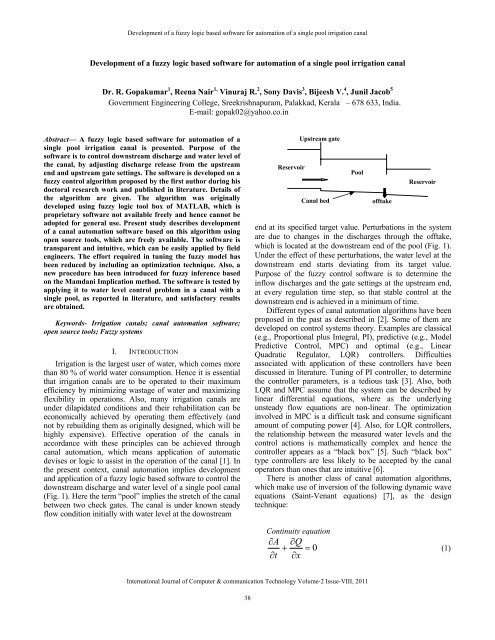
<strong>Development</strong> <strong>of</strong> a <strong>fuzzy</strong> <strong>logic</strong> <strong>based</strong> s<strong>of</strong>tware <strong>for</strong> <strong>automation</strong> <strong>of</strong> a single pool irrigation canal<strong>Development</strong> <strong>of</strong> a <strong>fuzzy</strong> <strong>logic</strong> <strong>based</strong> s<strong>of</strong>tware <strong>for</strong> <strong>automation</strong> <strong>of</strong> a single pool irrigation canalDr. R. Gopakumar 1 , Reena Nair 1, Vinuraj R. 2 , Sony Davis 3 , Bijeesh V. 4 , Junil Jacob 5Government Engineering College, Sreekrishnapuram, Palakkad, Kerala – 678 633, India.E-mail: gopak02@yahoo.co.inAbstract— A <strong>fuzzy</strong> <strong>logic</strong> <strong>based</strong> s<strong>of</strong>tware <strong>for</strong> <strong>automation</strong> <strong>of</strong> asingle pool irrigation canal is presented. Purpose <strong>of</strong> thes<strong>of</strong>tware is to control downstream discharge and water level <strong>of</strong>the canal, by adjusting discharge release from the upstreamend and upstream gate settings. The s<strong>of</strong>tware is developed on a<strong>fuzzy</strong> control algorithm proposed by the first author during hisdoctoral research work and published in literature. Details <strong>of</strong>the algorithm are given. The algorithm was originallydeveloped using <strong>fuzzy</strong> <strong>logic</strong> tool box <strong>of</strong> MATLAB, which isproprietary s<strong>of</strong>tware not available freely and hence cannot beadopted <strong>for</strong> general use. Present study describes development<strong>of</strong> a canal <strong>automation</strong> s<strong>of</strong>tware <strong>based</strong> on this algorithm usingopen source tools, which are freely available. The s<strong>of</strong>tware istransparent and intuitive, which can be easily applied by fieldengineers. The ef<strong>for</strong>t required in tuning the <strong>fuzzy</strong> model hasbeen reduced by including an optimization technique. Also, anew procedure has been introduced <strong>for</strong> <strong>fuzzy</strong> inference <strong>based</strong>on the Mamdani Implication method. The s<strong>of</strong>tware is tested byapplying it to water level control problem in a canal with asingle pool, as reported in literature, and satisfactory resultsare obtained.Keywords- Irrigation canals; canal <strong>automation</strong> s<strong>of</strong>tware;open source tools; Fuzzy systemsI. INTRODUCTIONIrrigation is the largest user <strong>of</strong> water, which comes morethan 80 % <strong>of</strong> world water consumption. Hence it is essentialthat irrigation canals are to be operated to their maximumefficiency by minimizing wastage <strong>of</strong> water and maximizingflexibility in operations. Also, many irrigation canals areunder dilapidated conditions and their rehabilitation can beeconomically achieved by operating them effectively (andnot by rebuilding them as originally designed, which will behighly expensive). Effective operation <strong>of</strong> the canals inaccordance with these principles can be achieved throughcanal <strong>automation</strong>, which means application <strong>of</strong> automaticdevises or <strong>logic</strong> to assist in the operation <strong>of</strong> the canal [1]. Inthe present context, canal <strong>automation</strong> implies developmentand application <strong>of</strong> a <strong>fuzzy</strong> <strong>logic</strong> <strong>based</strong> s<strong>of</strong>tware to control thedownstream discharge and water level <strong>of</strong> a single pool canal(Fig. 1). Here the term “pool” implies the stretch <strong>of</strong> the canalbetween two check gates. The canal is under known steadyflow condition initially with water level at the downstreamReservoirUpstream gateCanal bedPool<strong>of</strong>ftakeReservoirFigure 1. Schematic diagram <strong>of</strong> the single-pool canalend at its specified target value. Perturbations in the systemare due to changes in the discharges through the <strong>of</strong>ftake,which is located at the downstream end <strong>of</strong> the pool (Fig. 1).Under the effect <strong>of</strong> these perturbations, the water level at thedownstream end starts deviating from its target value.Purpose <strong>of</strong> the <strong>fuzzy</strong> control s<strong>of</strong>tware is to determine theinflow discharges and the gate settings at the upstream end,at every regulation time step, so that stable control at thedownstream end is achieved in a minimum <strong>of</strong> time.Different types <strong>of</strong> canal <strong>automation</strong> algorithms have beenproposed in the past as described in [2]. Some <strong>of</strong> them aredeveloped on control systems theory. Examples are classical(e.g., Proportional plus Integral, PI), predictive (e.g., ModelPredictive Control, MPC) and optimal (e.g., LinearQuadratic Regulator, LQR) controllers. Difficultiesassociated with application <strong>of</strong> these controllers have beendiscussed in literature. Tuning <strong>of</strong> PI controller, to determinethe controller parameters, is a tedious task [3]. Also, bothLQR and MPC assume that the system can be described bylinear differential equations, where as the underlyingunsteady flow equations are non-linear. The optimizationinvolved in MPC is a difficult task and consume significantamount <strong>of</strong> computing power [4]. Also, <strong>for</strong> LQR controllers,the relationship between the measured water levels and thecontrol actions is mathematically complex and hence thecontroller appears as a “black box” [5]. Such “black box”type controllers are less likely to be accepted by the canaloperators than ones that are intuitive [6].There is another class <strong>of</strong> canal <strong>automation</strong> algorithms,which make use <strong>of</strong> inversion <strong>of</strong> the following dynamic waveequations (Saint-Venant equations) [7], as the designtechnique:Continuity equation∂A∂Q+ = 0∂t∂x(1)International Journal <strong>of</strong> Computer & communication Technology Volume-2 Issue-VIII, 201138
<strong>Development</strong> <strong>of</strong> a <strong>fuzzy</strong> <strong>logic</strong> <strong>based</strong> s<strong>of</strong>tware <strong>for</strong> <strong>automation</strong> <strong>of</strong> a single pool irrigation canalMomentum equation∂Q+∂t2⎡Q⎤ ∂h⎢ ⎥ + gA − gAS0x ⎣ A ⎦ ∂x∂∂+ gAS f= 0where A is flow cross sectional area, h is flow depth, Q isdischarge, S 0 is bed slope, S f is friction slope, g isacceleration due to gravity, t is time variable and x is spacevariable. Gate Stroking [8] and CLIS [9] are examples <strong>for</strong>the algorithms coming under this class.The Gate Stroking is a feed <strong>for</strong>ward control algorithm,suitable <strong>for</strong> scheduled <strong>of</strong>ftake discharge changes, where the<strong>of</strong>ftake discharge changes are known a priori. It is <strong>based</strong> onthe method <strong>of</strong> characteristics, which is more complex. Theinherent difficulties and impracticality <strong>of</strong> Gate Stroking havebeen demonstrated in literature [10, 11]. Finite differencealternatives <strong>for</strong> the Gate Stroking method were also proposed[12, 13]. These algorithms involve inversion <strong>of</strong> thegoverning equations (1) and (2) in both time and space. Butthe in<strong>for</strong>mation from initial conditions and transientboundary conditions degrades with time due to friction andhence backward computation in time can cause instability[14]. However, the problem <strong>of</strong> instability is not applied toinverse computations in space and a feed back controlalgorithm <strong>of</strong> this type, suitable <strong>for</strong> unscheduled <strong>of</strong>ftakedischarge changes, was reported later [15]. CLIS [9] is amodified version <strong>of</strong> this algorithm, made suitable <strong>for</strong>scheduled flow changes also. For all these algorithms, therecovery time, which is the time period in which thecontrolled variables are expected to attain their target values,is taken as the upstream wave traveling time, which is muchmore than the physically correct downstream wave travelingtime. Additionally, CLIS makes use <strong>of</strong> linearized version <strong>of</strong>the Saint-Venant equations <strong>for</strong> the inverse modeling whereas the underlying system dynamics are nonlinear.Reference [16] describes development <strong>of</strong> a <strong>fuzzy</strong> <strong>logic</strong><strong>based</strong> dynamic wave model inversion algorithm <strong>for</strong> canalregulation, which was capable <strong>of</strong> overcoming thea<strong>for</strong>ementioned drawbacks <strong>of</strong> existing algorithms. Tuning <strong>of</strong>the algorithm was easy and computations were easy toimplement. No linearizations <strong>of</strong> the governing equationswere involved and the recovery time was rightly taken as thedownstream wave traveling time. The <strong>fuzzy</strong> controlalgorithm was transparent and intuitive and can be expectedto be more acceptable <strong>for</strong> canal operators as compared to“black box” type controllers. However, the algorithm wasdeveloped using the <strong>fuzzy</strong> <strong>logic</strong> tool box <strong>of</strong> MATLAB,which is proprietary s<strong>of</strong>tware not available freely and hencecannot be adopted <strong>for</strong> general use. Present study describesdevelopment <strong>of</strong> a canal <strong>automation</strong> s<strong>of</strong>tware <strong>based</strong> on thisalgorithm, <strong>for</strong> a single pool canal, where in freely availablecomponents are used.II.THEORETICAL ASPECTS(2)functions and <strong>fuzzy</strong> rules can be found in literature [18, 19].Fuzzy rule <strong>based</strong> models are suitable <strong>for</strong> nonlinear inputoutputmapping [18]. In <strong>fuzzy</strong> rule <strong>based</strong> modeling, a giveninput data undergoes the processes <strong>of</strong> fuzzification,application <strong>of</strong> <strong>fuzzy</strong> operators, implication, aggregation anddefuzzification, be<strong>for</strong>e finally <strong>for</strong>ming into output from themodel [20]. Various steps involved in the design <strong>of</strong> <strong>fuzzy</strong><strong>logic</strong> controllers have been discussed in literature [18].As mentioned previously, present study describesdevelopment <strong>of</strong> a canal <strong>automation</strong> s<strong>of</strong>tware <strong>based</strong> on the<strong>fuzzy</strong> control algorithm proposed in [16]. The <strong>fuzzy</strong>algorithm involves replacing (2) by a <strong>fuzzy</strong> rule <strong>based</strong> modelwhile retaining (1) in its complete <strong>for</strong>m. The <strong>fuzzy</strong> rule<strong>based</strong> model has been developed on fuzzification <strong>of</strong> a newmathematical model <strong>for</strong> dynamic wave velocity, obtained as:t( Discontinuity in gradient <strong>of</strong> Q )t( Discontinuity in gradient <strong>of</strong> A)t( ΔQ)( ΔA)tmm( Vw)m= = (3)twhere, ( V ) t w m is the wave velocity at point m along thecanal, at time t.Discontinuity in gradient <strong>of</strong> a flow parameter (Q or A), atpoint m and at time t, has been determined as the differencebetween its gradient corresponding to the final steadycondition (which the flow will attain under the effect <strong>of</strong> theperturbation) and its gradient corresponding to the conditionat time t, both gradients being evaluated at point m. The<strong>fuzzy</strong> rule <strong>based</strong> model is developed on fuzzification <strong>of</strong> (3).While computing the dynamic wave velocity (V w ) at anynode (i,j+1) in the computational domain (Fig. 2), thecorresponding values <strong>of</strong> ∆A and ∆Q are determinedapproximately by adopting the following discretization:ΔAΔQj + 1i=j + 1i=F.S F.S j+1 j+1[ Ai+1- Ai] -[ Ai+ 1- Ai](4)F.S F.S j+1 j+1[ Q - Q ] -[ Q - Q ](5)i+1ii+1In (4) and (5), the notations with superscript “F.S”indicate the values <strong>of</strong> the flow parameters corresponding tothe final steady state.Equation (1) has been discretized at the node (i,j), in thex-t computational domain (Fig. 2), using the Vasiliev scheme[21], which is an unconditionally stable implicit finitedifference scheme, as follows:j+1 j 1 j+1 j+[ A − A ] + [ Q − Q ] 01 1i ii+1 i-1=Δt2Δxwhere i = node number in the x – direction and j = nodenumber in the t – direction.imm(6)The concept <strong>of</strong> <strong>fuzzy</strong> <strong>logic</strong> was first introduced by Zadeh[17]. Details <strong>of</strong> <strong>fuzzy</strong> sets, <strong>fuzzy</strong> numbers, membershipInternational Journal <strong>of</strong> Computer & communication Technology Volume-2 Issue-VIII, 201139
<strong>Development</strong> <strong>of</strong> a <strong>fuzzy</strong> <strong>logic</strong> <strong>based</strong> s<strong>of</strong>tware <strong>for</strong> <strong>automation</strong> <strong>of</strong> a single pool irrigation canalTime ( t )1i-1,,j+1i,,j+1i,,jΔti+1,,j+12 N-1Distance (x)Figure 2. Computational domain <strong>for</strong> the <strong>fuzzy</strong> control algorithm:N = number <strong>of</strong> nodes in the x – direction, i = node number in the x –direction, j = node number in the t – direction.Here, it is assumed that the control is achieved by rapidmovement <strong>of</strong> check gates, which will result in the <strong>for</strong>mation<strong>of</strong> gravity waves. If the wave velocity (V w ) corresponding toa certain inflow discharge is assumed to remain constantover the entire pool under consideration then a set <strong>of</strong> crisprules can be written, <strong>based</strong> on (3) and applicable everywherein the pool, as IF ∆Q is low THEN ∆A is low, IF ∆Q ismedium THEN ∆A is medium, IF ∆Q is high THEN ∆A ishigh etc. where “low”, “medium”, “high” etc. arequantitative variables and ∆Q and ∆A indicate crispnumerical values. If the above assumption on V w holds goodonly approximately then the rules become <strong>fuzzy</strong>, “low”,“medium”, “high” etc. become linguistic variables and ∆Qand ∆A indicate <strong>fuzzy</strong> subsets. The <strong>fuzzy</strong> rule <strong>based</strong> model isdeveloped on this principle. A major advantage <strong>of</strong> the above<strong>fuzzy</strong> <strong>for</strong>mulation is that it is developed on fuzzification <strong>of</strong> amathematical model (3) relating the input and outputvariables. Hence the rules linking these variables can beaccurately specified. Such a <strong>fuzzy</strong> model works in the bestway and also the results are significantly better than the casewhere the model is developed using sample data [22]. Theerror, associated with the assumption on V w remainingapproximately constant in a pool, reduces as the waveamplitude reduces because as the amplitude reduces thewave resembles more closely a linear gravity wave whichpropagates downstream with minimum distortion,attenuation and change in velocity [23, 24, 25]. Hence it canbe expected that the algorithmic error will be a minimum andconsequently stable control at the downstream end will beachieved early in those cases where the final steady pr<strong>of</strong>ilecon<strong>for</strong>m to uni<strong>for</strong>m flow. Such a case is very difficult tocontrol by other existing algorithms [26]. S<strong>of</strong>tware in thepresent context has been developed <strong>for</strong> this particular case.III. DEVELOPMENT OF THE SOFTWAREThe s<strong>of</strong>tware consists <strong>of</strong> three modules; the first one <strong>for</strong>tuning, the second one <strong>for</strong> <strong>fuzzy</strong> inference and the third one<strong>for</strong> computing the required inflow rate, at the upstream end,ΔxNusing the first and second modules. The Graphical UserInterface <strong>of</strong> the s<strong>of</strong>tware is developed using ‘Qt’ and thecomputational modules are developed using 'C' language.For the applications specified in the algorithm, only one toone correspondence is used. There<strong>for</strong>e the <strong>fuzzy</strong> libraries andtool boxes given in [27, 28, 29] are not required as they aredesigned <strong>for</strong> a wide variety <strong>of</strong> applications.A. TuningTuning <strong>of</strong> the <strong>fuzzy</strong> control algorithm involvesdetermination <strong>of</strong> the membership function parameters (core,support and boundary) <strong>of</strong> each <strong>fuzzy</strong> subset and construction<strong>of</strong> the <strong>fuzzy</strong> rule base. It is done by considering a fictitiouscase where the flow corresponding to maximum designdischarge in the canal is uni<strong>for</strong>m at the upstream end. For abase flow corresponding to the maximum design dischargeand <strong>for</strong> various inflow discharges, respective values <strong>of</strong> ∆Qand ∆A are obtained by solving (3) along with the basicequation <strong>for</strong> gravity wave velocity [30] given below, whichhas been derived from momentum equation:VgA1= V2 +(A1Y1− A2Y ) (7)A (A − A )w 22 1 2In (7), the subscript 1 indicates the upstream end fromwhere the wave is produced and the subscript 2 indicates aneighboring section where the effect <strong>of</strong> the wave has not yetreached, V is flow velocity and Y is depth <strong>of</strong> centroid <strong>of</strong>the section below the free surface. The solution procedure isas follows. For a certain inflow discharge, ∆Q = Q 1 – Q 2 is aknown value. Also, as flow is uni<strong>for</strong>m at the upstream end,∆A can be replaced by A 1 -A 2 in (3). Thus in (3) and (7) theonly unknowns are A 1 and Y 1 . But Y1is a function <strong>of</strong> A 1 . S<strong>of</strong>or a trial value <strong>of</strong> A 1 corresponding value <strong>of</strong> Y 1 isdetermined and applied in (7) to determine V w . Same value<strong>of</strong> V w should be obtained when the above value <strong>of</strong> A 1 is usedin (3). If not, the above procedure is repeated with other trialvalues <strong>of</strong> A 1 until V w obtained from the two equations areequal. An optimization technique has been adopted to reducethe number <strong>of</strong> trials required in tuning. It involves comparingthe difference between V w values, resulting from (3) and (7),during successive trials and the computation will proceed inthat direction where the above difference will keep reducing.This is continued until the difference lies within somepermitted tolerance. Once the correct value <strong>of</strong> A 1 is obtained,the value <strong>of</strong> ∆A= A 1 -A 2 is calculated. Thus values <strong>of</strong> ∆Q and∆A are obtained <strong>for</strong> the specified inflow discharge. Thisprocedure is repeated <strong>for</strong> other inflow discharges also andrespective values <strong>of</strong> ∆Q and ∆A are determined. Thesevalues are stored in two arrays. Each value in the input array(∆Q) has a corresponding value in the output array (∆A)also, both having degree <strong>of</strong> membership equal to one (corevalues <strong>of</strong> the <strong>fuzzy</strong> sets). Then by adopting the method <strong>of</strong>partitioning [18], a set <strong>of</strong> triangular membership functionsand <strong>fuzzy</strong> rules are derived relating ∆Q and ∆A.International Journal <strong>of</strong> Computer & communication Technology Volume-2 Issue-VIII, 201140
<strong>Development</strong> <strong>of</strong> a <strong>fuzzy</strong> <strong>logic</strong> <strong>based</strong> s<strong>of</strong>tware <strong>for</strong> <strong>automation</strong> <strong>of</strong> a single pool irrigation canalB. Fuzzy InferenceThe s<strong>of</strong>tware introduces a new procedure to compute theoutput (∆A) <strong>for</strong> a given input (∆Q), <strong>based</strong> on the MamdaniImplication method <strong>of</strong> inference [31] and the CentroidMethod <strong>of</strong> defuzzification [18], as described below.Suppose x n is the given input data (∆Q), with m 1 and m 2as the corresponding degrees <strong>of</strong> membership in theneighboring membership functions shown in Fig. 3. Sincethese membership functions have been developed bymethod <strong>of</strong> partitioning, they will <strong>for</strong>m isosceles triangles.µ(x i )Figure 3. Fuzzification <strong>of</strong> input dataThe value <strong>of</strong> x 2 nearest to x n is found from the array <strong>of</strong>∆Q. The values x 1 , x 3 and x 4 are also obtained from the samearray. Then the values <strong>of</strong> m 1 and m 2 are computed asfollows:tanθ = 1/ (x 2 - x 1 ). m 1 = (x 3 -x n ) tanθ. m 2 = (x n -x 2 ) tanθThere is one to one correspondence between the inputand output <strong>fuzzy</strong> sets stored in the two arrays. Hence m 1 andm 2 can be easily mapped to the corresponding outputmembership functions, as shown in Fig. 4.µ(y i )1m 1m 21m 1m 2x 1(a 1, b 1 )θ(a 2, b 2 )x 2 x 3 x 4x nθ 1 θ 2Figure 4. Computing the output membership function by implication.The values <strong>of</strong> a 2 , a 3 , a 4 and a 5 shall be obtained as follows:Calculation <strong>of</strong> a 2tan θ 1 = 1/(y 2 – a 1 ). Suppose o 1 = a 2 – a 1.Then, tan θ 1 = b 2 /o1. But b 2 = m 1.There<strong>for</strong>e, o 1 = m 1 /tan θ 1. Hence, a 2 = a 1 + o 1 .Calculation <strong>of</strong> a 3tan θ 2 = 1/(y 3 – y 2 ). Suppose o 2 = y 3 – a 3.Then, tan θ 2 = b 3 /o 2. . But b 3 = m 1There<strong>for</strong>e, o 2 = m 1 /tan θ 2. Hence, a 3 = y 3 – o 2 .Calculation <strong>of</strong> a 4Suppose o 3 = y 3 – a 4 . Then, tan θ 2 = b 4 /o 3.θ(a 3, b 3 )(a 4, b 4 )(a 5, b 5 )y 2y 3 (a 6, b 6 )θΔQΔABut b 4 = m 2There<strong>for</strong>e, o 3 = m 2 /tan θ 2. Hence, a 4 = y 3 – o 3Calculation <strong>of</strong> a 5 is similar to that <strong>of</strong> a 4The above calculations are <strong>for</strong> the case when m 1 > m 2 .Calculations <strong>for</strong> the case where m 1 < m 2 is similar.For the resulting polygon with coordinates as shown inthe Fig. 5, the x-coordinate <strong>of</strong> the centroid , ΔA, which isthe required output, is calculated using following equations[32].6P 1 i i+1 i+1 ii=1= / 2∑ ( a b ) − ( a b )(8)6∑ΔA= 1/(6P ) ( a + a(9)i=1ii+ 1 ) × ( aibi+1 − ai+1bi)This module per<strong>for</strong>ms only mathematical calculations.The computational cost is independent <strong>of</strong> any characteristics<strong>of</strong> the canal and hence the time and space complexity isconstant.C. Steps in Computation1. Recovery time (Δt) is obtained as the downstreamwave traveling time.2. The canal reach is discretized into (N-1) subreachesusing N nodes, as shown in Fig. 2; node 1being at the upstream end and node N at thedownstream end.3. Computation starts at the last node N, assumingthat Q and h at this node will be equal to theirtarget values at the end <strong>of</strong> the time step (Δt).4. Q and h at the nodes N-1, N-2 …,2, 1 are obtainedsuccessively, by application <strong>of</strong> (6) and the <strong>fuzzy</strong>rule <strong>based</strong> model. Note that A is a function <strong>of</strong> hdepending on geometry <strong>of</strong> the canal.5. The upstream gate is adjusted to release thedischarge computed at node 1 <strong>for</strong> the recovery timeperiod (Δt).6. If the flow depth (h) at node N at the end <strong>of</strong> Δtdeviate from its target value then repeat the abovesteps <strong>for</strong> the next Δt.7. Otherwise stop.The computation module per<strong>for</strong>ms a set <strong>of</strong> operations <strong>for</strong>each node in the pool. Hence the time complexity is linearwith the number <strong>of</strong> nodes in the pool. But the number <strong>of</strong>nodes is not a parameter that takes very high values.There<strong>for</strong>e the computational time <strong>of</strong> this module will notvary much with the number <strong>of</strong> nodes.IV. SOFTWARE TESTINGThe s<strong>of</strong>tware is tested by comparing its outputs with thatobtained using MATLAB <strong>fuzzy</strong> <strong>logic</strong> tool box [16]. Thes<strong>of</strong>tware has been applied to water level control problem in afictitious canal with a single pool [15]. Schematic diagram <strong>of</strong>the canal is shown in Fig. 5. The canal length (L) is 5000 m,bottom width 5.0 m and side slope 1.0. Its bottom slope isInternational Journal <strong>of</strong> Computer & communication Technology Volume-2 Issue-VIII, 201141
<strong>Development</strong> <strong>of</strong> a <strong>fuzzy</strong> <strong>logic</strong> <strong>based</strong> s<strong>of</strong>tware <strong>for</strong> <strong>automation</strong> <strong>of</strong> a single pool irrigation canal0.0003. Width <strong>of</strong> upstream and downstream rectangulargates is 5.0 m with discharge coefficient 0.75. There is aconstant head reservoir at upstream end and another one atdownstream end. Their respective water levels are 6.3 m and2.8 m. Also bottom elevation <strong>of</strong> the pool at the upstream endis 1.5 m and at the downstream end is 0.0 m. An <strong>of</strong>ftakecanal is provided just upstream <strong>of</strong> the downstream gate.Target water depth at downstream end <strong>of</strong> the canal is 3.46 m,which corresponds to normal depth at a peak flow rate <strong>of</strong> 40m 3 /s.Figure 5. Schematic diagram <strong>of</strong> the single-pool canal used <strong>for</strong> testingthe canal <strong>automation</strong> s<strong>of</strong>tware.For a base flow corresponding to the peak flow rate <strong>of</strong> 40m 3 /s, and <strong>for</strong> various inflow discharges ranging from 35 m 3 /sto 45 m 3 /s, corresponding values <strong>of</strong> ∆Q and ∆A are obtainedand membership functions are developed by following theprocedure explained under the section “Tuning”. They areshown in Fig. 6. In the figure “L” implies “low” values and“H” implies “high” values. Higher the coefficient <strong>of</strong> “L” and“H” higher will be their gradation towards “low” and “high”values respectively. The <strong>fuzzy</strong> rules, connecting theantecedent ∆Q and the consequent ∆A, are derived in the<strong>for</strong>m IF ∆Q is “a” THEN ∆A is “a” where “a” take values inascending order from 9L to 9H (Fig. 6). Hence a total <strong>of</strong>eighteen rules are included in the <strong>fuzzy</strong> rule base.(a)Membership degreeMembership degree10.59L 8L 7L 6L 5L 4L 3L 2L L H 2H 3H 4H 5H 6H 7H 8H 9H0-5 -4 -3 -2 -1 0 1 2 3 4 5∆Q (m 3 /s)(b)10.56.3 m1.5 mFlowBed slope = 0.0003Offtake5000 m3.46 m2.8 m0.0 m9L 8L 7L 6L 5L 4L 3L 2L L H 2H 3H 4H 5H 6H 7H 8H 9H0-0.803 -0.6037 -0.4044 -0.2051 -0.0058 0.1935 0.3928 0.5921 0.7914∆A (m 2 )Figure 6. Membership functions <strong>of</strong> the <strong>fuzzy</strong> model <strong>for</strong> the single-poolcanal: (a) input membership functions, (b) output membership functions.Initially the flow is steady in the canal with a discharge<strong>of</strong> 20 m 3 /s. There is no flow in the <strong>of</strong>ftake canal and theentire flow is diverted to the downstream reservoir. Flow inthe <strong>of</strong>ftake canal is then increased from 0 to 20 m 3 /s in 2minutes. With such a disturbance, the response <strong>of</strong> the systemis studied. The computational nodes are placed at a distanceinterval (Δx) <strong>of</strong> 100 m each. The recovery time (Δt) is takenas downstream wave traveling time <strong>of</strong> 797 s [15]. At everyrecovery time step, the upstream gate opening is adjusted, inaccordance with the gate equation given in [15] so as tomaintain the constant gate discharge output from the <strong>fuzzy</strong>control algorithm.The simulation results include variation <strong>of</strong> the upstreamgate opening with time (Fig. 7), development <strong>of</strong> watersurface pr<strong>of</strong>ile along the canal with time (Fig. 8), variation <strong>of</strong>the discharge with time at both upstream and downstreamends (Fig. 9) and variation <strong>of</strong> the change in water level withtime at both these locations (Fig. 10). These results arecomparable to those obtained using MATLAB <strong>fuzzy</strong> <strong>logic</strong>tool box [16] and hence it can be concluded that the s<strong>of</strong>twareis giving accurate outputs.Gate opening (m)Water surface elevation (m)4.543.532.521.510.500 20 40 60 80 100 120 140Time (minutes)Figure 7. Variation <strong>of</strong> the upstream gate opening <strong>of</strong> the single-poolcanal with time during control14131211109Target pr<strong>of</strong>ile4105 s2511 sCanal bed120 s80 1000 2000 3000 4000 5000Distance (m)Figure 8. <strong>Development</strong> <strong>of</strong> water surface pr<strong>of</strong>iles with time in thesingle-pool canal during controlInternational Journal <strong>of</strong> Computer & communication Technology Volume-2 Issue-VIII, 201142
<strong>Development</strong> <strong>of</strong> a <strong>fuzzy</strong> <strong>logic</strong> <strong>based</strong> s<strong>of</strong>tware <strong>for</strong> <strong>automation</strong> <strong>of</strong> a single pool irrigation canalDischarge (m 3 /s)70605040302010Upstream endDownstream endACKNOWLEDGMENTThe funding provided by CERD (Centre <strong>for</strong> EngineeringResearch and <strong>Development</strong>), Kerala, in carrying out thisresearch is gratefully acknowledged.REFERENCES[1] A.J. Clemmens. “Editorial”, Journal <strong>of</strong> Irrigation and DrainageEngineering, ASCE, vol. 124(1), 1998, pp. 1-2.Change in water level (m)00 20 40 60 80 100 120 140Time (minutes)Figure 9. Variation <strong>of</strong> discharge with time, at upstream anddownstream ends <strong>of</strong> the single-pool canal during control1.41.210.80.60.40.20-0.2-0.4-0.6Upstream endDownstream end0 20 40 60 80 100 120 140Time (minutes)Figure 10. Variation <strong>of</strong> change in water level with time, at upstream anddownstream ends <strong>of</strong> the single-pool canal during controlV. CONCLUSIONSA s<strong>of</strong>tware <strong>for</strong> <strong>automation</strong> <strong>of</strong> a single-pool canal, <strong>based</strong>on a <strong>fuzzy</strong> control algorithm, is presented in this study. The<strong>fuzzy</strong> algorithm was originally developed using MATLAB<strong>fuzzy</strong> <strong>logic</strong> tool box, which is not freely available. Thus theoriginal work was unsuitable <strong>for</strong> common field applications.This problem has been overcome in the present study usingfree and open source packages. Additionally, existing canalcontrol s<strong>of</strong>tware are <strong>based</strong> on either control systems theoryor dynamic wave model inversion, both require strongtheoretical background <strong>for</strong> application. This difficulty doesnot arise <strong>for</strong> the present s<strong>of</strong>tware. It is transparent andintuitive and can be easily applied by field engineers.Number <strong>of</strong> trials required <strong>for</strong> tuning the <strong>fuzzy</strong> model hasbeen effectively reduced by including an optimizationtechnique. Also, a new procedure has been introduced <strong>for</strong><strong>fuzzy</strong> inference <strong>based</strong> on the Mamdani Implication method.The technical details <strong>of</strong> computation are abstracted from theend user and there<strong>for</strong>e the s<strong>of</strong>tware is extremely userfriendly. As the front end was designed using Qt and thecomputational modules uses 'C' language, only a minimumnumber <strong>of</strong> freely available packages are required to installthe s<strong>of</strong>tware. The s<strong>of</strong>tware has been tested by applying it to acanal control problem reported in literature. The resultsobtained are comparable to those obtained using MATLAB<strong>fuzzy</strong> <strong>logic</strong> tool box, which proves that the s<strong>of</strong>tware is givingaccurate outputs.[2] P-O. Malaterre, D.C. Rogers and J. Schuurmans.“Classification <strong>of</strong> canal control algorithms”, Journal <strong>of</strong> Irrigationand Drainage Engineering, ASCE, vol. 124(1), 1998, pp. 3-10.[3] B.T. Wahlin and A.J. Clemmens. “Per<strong>for</strong>mance <strong>of</strong> historicdownstream canal control algorithms on ASCE Test Canal 1”,Journal <strong>of</strong> Irrigation and Drainage Engineering, ASCE, vol.128(6), 2002, pp. 365-375.[4] B.T. Wahlin. “Per<strong>for</strong>mance <strong>of</strong> model predictive control onASCE Test Canal 1”, Journal <strong>of</strong> Irrigation and DrainageEngineering, ASCE, vol. 130(3), 2004, pp. 227-238.[5] A.J. Clemmens and J. Schuurmans. “Simple optimaldownstream feedback canal controllers: theory”, Journal <strong>of</strong>Irrigation and Drainage Engineering, ASCE, vol. 130(1), 2004,pp. 26-34.[6] V.M. Ruiz-Carmona, A.J. Clemmens and J. Schuurmans.“Canal control algorithm <strong>for</strong>mulations”, Journal <strong>of</strong> Irrigation andDrainage Engineering, ASCE, vol. 124(1), 1998, pp. 31-39.[7] V.T. Chow, D.R. Maidment and L.W.Mays. AppliedHydrology, McGraw-Hill International Editions. 1988.[8] E.B. Wylie. “Control <strong>of</strong> transient free-surface flow”, Journal <strong>of</strong>Hydraulic Division, ASCE, vol. 95(HY1), 1969, pp. 347-361.[9] F. Liu, J. Feyen, P-O. Malaterre, J-P Baume and P. Kosuth.“<strong>Development</strong> and evaluation <strong>of</strong> canal <strong>automation</strong> algorithmCLIS”, Journal <strong>of</strong> Irrigation and Drainage Engineering, ASCE,vol. 124(1), 1998, pp. 40-46.[10] E. Bautista, T.S. Strelk<strong>of</strong>f, and A.J. Clemmens. “Generalcharacteristics <strong>of</strong> solutions to the open-channel flow, feed <strong>for</strong>wardcontrol problem”, Journal <strong>of</strong> Irrigation and Drainage Engineering,ASCE, vol. 129(2), 2003, pp. 129-137.[11] E. Bautista and A.J. Clemmens. “Volume compensationmethod <strong>for</strong> routing irrigation canal demand changes”, Journal <strong>of</strong>Irrigation and Drainage Engineering, ASCE, vol. 131(6), 2005, pp.494-503.[12] G.Chevereau. Contribution a l’étude de la régulation dans lessystèmes hydrauliques a surface libre, Ph.D. thesis, Institut NationalPolytechnique de Grenoble, Grenoble, France. 1991.[13] F. Liu, J. Feyen and J. Berlamont. “Computation method <strong>for</strong>regulating unsteady flow in open channels”, Journal <strong>of</strong> Irrigationand Drainage Engineering, ASCE, vol. 118(10), 1992, pp. 674-689.International Journal <strong>of</strong> Computer & communication Technology Volume-2 Issue-VIII, 201143
<strong>Development</strong> <strong>of</strong> a <strong>fuzzy</strong> <strong>logic</strong> <strong>based</strong> s<strong>of</strong>tware <strong>for</strong> <strong>automation</strong> <strong>of</strong> a single pool irrigation canal[14] J.A. Cunge, F.M. Holly Jr and A.Verwey. Practical Aspects <strong>of</strong>Computational River Hydraulics, London: Pitman. 1980.[15] F. Liu, J. Feyen and J. Berlamont. “Downstream controlalgorithm <strong>for</strong> Irrigation canals”, Journal <strong>of</strong> Irrigation and DrainageEngineering, ASCE, vol. 120(3), 1994, pp. 468-483.[16] R. Gopakumar and P.P Mujumdar. “A <strong>fuzzy</strong> <strong>logic</strong> <strong>based</strong>dynamic wave model inversion algorithm <strong>for</strong> canal regulation”,Hydro<strong>logic</strong>al Processes, Vol. 23, No. 12, 2009. pp. 1739-1752.[17] L.A. Zadeh. “Fuzzy Sets”, In<strong>for</strong>mation and Control, 8, 1965,338-353.[18] T.J. Ross. Fuzzy Logic with Engineering Applications,McGraw-Hill International Editions. 1995[19] H.J. Zimmermann. Fuzzy Set Theory and Its Applications,Kluwer Academic Publishers. 1991.[20] MATLAB. Fuzzy Logic Tool Box, The Math Works. 1995.[21] J.A. Liggett and J.A Cunge. “Numerical methods <strong>of</strong> solution <strong>of</strong>the unsteady flow equations”, Unsteady flow in open channels, KMahmood and V Yevjevich eds. Volume 1. Water ResourcesPublications. 1975.[22] S.O. Russell and P.F. Campbell. “Reservoir operating ruleswith <strong>fuzzy</strong> programming”, Journal <strong>of</strong> Water Resources Planningand Management, ASCE, vol. 122(3), 1996, pp.165-170.[23] M.G. Ferrick. “Simple wave and monoclinal wave models:River flow surge applications and implications”, Water ResourcesResearch, vol. 41(W11402), 2005, pp. 1-19.[24] V.M. Ponce and D.B. Simons. “Shallow wave propagation inopen channel flow”, Journal <strong>of</strong> Hydraulic Division, ASCE, vol.103(HY12), 1977, pp. 1461-1476.[25] C.W-S. Tsai and B.C. Yen. “Linear analysis <strong>of</strong> shallow waterwave propagation in open channels”, Journal <strong>of</strong> EngineeringMechanics, ASCE, vol. 127(5), 2001, pp. 459-472.[26] A.J. Clemmens, T.F. Kacerek, B. Grawitz, W. Schuurmans..Test cases <strong>for</strong> canal control algorithms. Journal <strong>of</strong> Irrigation andDrainage Engineering, ASCE, 124(1), 1998, pp. 23-30.[27] FISLAB: the Fuzzy Inference tool-box <strong>for</strong> SCILAB. Ann.Univ. Tibiscus Comp. Sci. Series V, 2007, pp. 105-114[28] Fuzzy Lite – A <strong>fuzzy</strong> <strong>logic</strong> library written in C++.http://code.google.com/p/<strong>fuzzy</strong>-lite, accessed on 02/02/2011[29] E.L. Posselt , L.F.D.R.E Silva, R. Frozza and R. Fredimolz.“Qualitative Study <strong>of</strong> S<strong>of</strong>tware <strong>for</strong> Fuzzy Systems Simulation and<strong>Development</strong>”, Proceedings <strong>of</strong> the 11th WSEAS (World Scientificand Engineering Academy and Society ) international conferenceon neural networks, evolutionary computing and Fuzzy systems,Stevens Point, Wisconsin, USA. 2010[30] M.H. Chaudhry. Open-Channel Flow, Englewood Cliffs, N.J:Prentice-Hall. 1993.[31] E.H. Mamdani and S. Assilian. “An experiment in linguisticsynthesis with a <strong>fuzzy</strong> <strong>logic</strong> controller”, International Journal <strong>of</strong>Man-Machine Studies, vol. 7(1), 1975, pp.1-13.[32] http://en.wikipedia.org/wiki/centroid, accessed on 30/5/2011International Journal <strong>of</strong> Computer & communication Technology Volume-2 Issue-VIII, 201144


