Download Manual - Scag Power Equipment
Download Manual - Scag Power Equipment
Download Manual - Scag Power Equipment

Create successful ePaper yourself
Turn your PDF publications into a flip-book with our unique Google optimized e-Paper software.
MODEL GC-STC-CSTHIS MANUAL CONTAINS THE OPERATINGINSTRUCTIONS AND SAFETY INFORMA-TION FOR YOUR SCAG ACCESSORY. READ-ING THIS MANUAL WILL PROVIDE YOUWITH MAINTENANCE AND ADJUSTMENTPROCEDURES TO KEEP YOUR ACCESSORYPERFORMING TO MAXIMUM EFFICIENCY.THE SPECIFIC MODELS THAT THIS BOOKCOVERS ARE CONTAINED ON THE INSIDECOVER. BEFORE OPERATING YOUR MA-CHINE, PLEASE READ ALL THE INFORMA-TION ENCLOSED.OPERATOR’S MANUALPART NUMBER 03139
WARNINGFAILURE TO FOLLOW SAFE OPERATING PRACTICESMAY RESULT IN SERIOUS INJURY.* Keep all safety shields in place.* Before performing any maintenance or service, stop the machine andremove the spark plug wire.* If a mechanism becomes clogged, stop the engine and wait for all movingparts to come to a complete halt before cleaning.* Keep hands, feet and clothing away from power-driven parts.* Read this manual completely as well as the Operator's <strong>Manual</strong> that camewith your mower.* Keep others off the tractor (only one person at a time).REMEMBER - YOUR MOWER IS ONLY AS SAFE AS THE OPERATOR!Hazard control and accident prevention are dependent upon the awareness,concern, prudence, and proper training of the personnel involved in the operation,transport, maintenance, and storage of the equipment.This manual covers the operating instructionsand illustrated parts list for:GC-STC-CS with a serial number of 9540001 to 9549999
1.1 INTRODUCTIONThis manual has been prepared to provide theinformation you need to correctly assemble, operate,and maintain this grass catcher. Read it carefully andkeep it for future reference.The replacement of any part on this product by otherthan the manufacturer's authorized replacement partmay adversely affect the performance, durability orsafety of this product.USE OF OTHER THAN ORIGINAL SCAGREPLACEMENT PARTS WILL VOID THEWARRANTY.If additional information or service is needed that isnot outlined in this manual, please contact your <strong>Scag</strong><strong>Power</strong> <strong>Equipment</strong> dealer. <strong>Scag</strong> dealers are trained inthe latest service methods and carry a full line of <strong>Scag</strong>replacement parts.When ordering parts, always provide the completemodel number of your catcher.All information provided in this manual is based uponinformation available at the time of printing. <strong>Scag</strong><strong>Power</strong> <strong>Equipment</strong> reserves the right to make changesat any time without notice or obligation.1.2 DIRECTION REFERENCEThe "Right" and "Left", "Front" and "Rear" of themachine are referenced from the normal operatingposition.2.1 SAFETY AND OPERATINGINSTRUCTIONS-NOTE-To avoid personal injury, it is imperative that allsafety instructions be observed.1. Read this operator's manual and theoperator's manual that is supplied with themachine this attachment is used on.A replacement manual is available from yourauthorized <strong>Scag</strong> Service Dealer or by contacting:<strong>Scag</strong> <strong>Power</strong> <strong>Equipment</strong>, Service Department at P.O.Box 152, Mayville, WI 53050. You may also contactus through our website at www.scag.com. Pleaseindicate the complete model and number of your<strong>Scag</strong> product when ordering a replacement manual.WARNINGDO NOT OPERATE WITHOUT DISCHARGE CHUTE, MULCHINGKIT, OR ENTIRE GRASS CATCHER INSTALLED2. Before removing material from hopper,disengage the mower and wait for all movementto stop.3. ALWAYS turn the engine OFF, remove the keyand wait for all movement to stop beforeservicing or cleaning the mower or the grasscatcher.4. Do not modify or alter any component of thegrass catcher attachment or mower.5. Do not allow any passengers to ride on the grasscatcher attachment or on the mower.2.2 GRASS CATCHING OPERATION1. With the hopper door closed, engage the deckdrive.2. Proceed to mow until the hopper is full.1
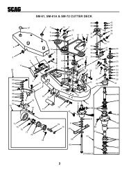
3.1 ASSEMBLY INSTRUCTIONS FOR 48"AND 52" CUTTER DECK-NOTE-Use the illustrated parts list as a part numberreference when following the assemblyinstructions.1. Remove all packaging materials. Lay out themounting hardware and the catcher assemblyparts for easy access. Prepare the work areamaking sure that it is a clean, safe environment.2. Remove the discharge chute from the cutterdeck. See Figure 3-1.-NOTE-Do not discard the discharge chute ormounting hardware. The discharge chuteMUST be reinstalled anytime the grasscatcher is removed from the machine.3. Remove the right side belt cover to gain access tothe spindle assembly. Remove the front u-nutfrom the cutter deck bracket. See Figure 3-1.REMOVE DISCHARGECHUTE ANDHARDWAREWARNINGDO NOT OPERATE WITHOUT DISCHARGE CHUTE, MULCHINGKIT, OR ENTIRE GRASS CATCHER INSTALLED-NOTE-Retain the original belt cover. This coverMUST be reinstalled anytime thecomplete catcher system is removed.INSTALL PULLEYON RH SPINDLE SHAFT -ON TOP OF EXISTINGSPINDLE DRIVEPULLEYREMOVE EXISTINGRT. SIDE BELTCOVER-NOTE-There are two (2) pulleys supplied with this kit.Small pulley (3-3/4" O.D.) is for 48" deck.Large Pulley (4.0" O.D.) is for 52" deck.4. Install the grass catcher pulley onto the spindleassembly. Apply loctite to both pulley setscrewsand tighten. See Figure 3-1.When installing this grass catcher on anAdvantage deck, install the front baffle to thecutter deck. See Figure 3-2. Secure using thefollowing hardware:(2) 04017-05 Bolt, Hex Head 1/4-20 x 3/4"(2) 04019-02 Nut, Serrated Flange 1/4-20(2) 04003-23 Bolt, Carriage 3/8-16 x 1"(2) 04041-07 Flatwasher(2) 04021-09 Nut, Elastic Stop 3/8-1604017-0504021-0904001-0904040-1504021-1004041-0704019-02DischargeBaffle04021-0904041-0704003-23FIGURE 3-25. Install the blower mounting bracket to the deckusing carriage bolts (p/n 04003-11), lockwashers,and nuts. Do not fully tighten the hardware atthis time. See Figure 3-3, Page 4.REMOVE U-NUTRIGHT SIDE OFCUTTER DECK SHOWN(Note: Some parts not shown for viewing purposes.)Figure 1- GC-STC install art6. Install the catch plate (p/n 423297) to the blowerassembly using carriage bolts (p/n 04003-12)facing upward. Secure with lockwashers andelastic stop nuts. Do not fully tighten thehardware at this time. See Figure 3-4, Page 4.FIGURE 3-17. Install the blower assembly to the mountingbracket and secure with the mounting pin.See Figure 3-4, Page 4.3
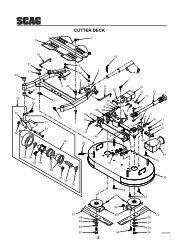
REAR OFCUTTER DECKDISCHARGE CHUTE OPENINGFRONT OFCUTTER DECKVIEW FROM RIGHT SIDEOF CUTTER DECKFigure 2- GC-STC install artFIGURE 3-3LOCKWASHERCATCHPLATEELASTICSTOP NUTBLOWERASSEMBLYHAIRPINMOUNTINGBRACKETCARRIAGEBOLTSPINPROPERLYSERVICEENGINEWITHOILANDFUEL.ELASTICSTOP NUTSAND LOCKWASHERSRIGHT SIDE OFCUTTER DECK SHOWNGC-STC install art 3(Note: Some parts not shown for viewing purposes.)FIGURE 3-44
Figure 4 A GC-STT Install Art8. Align the blower assembly with the dischargeopening of the cutter deck. Tighten the hardwarefor the mounting bracket. Then tighten thehardware for the catch plate.9. Install the large hair pin through the rear hole inthe discharge chute mounting bracket. SeeFigure 3-4, Page 4.-NOTE-The hopper dump handle can be installed oneither side for operator convenience. Wheninstalling this grass catcher on a machinewith the Roll Over Protection System (ROPS),the curved handle will need to be installed onthe right side.10. Install the belt to the spindle pulley. Whenreplacing the belt, see figure below.BACK SIDEIDLER PULLEYBLOWERPULLEYFRONT SIDEIDLER PULLEY11. Install the new belt covers and secure. Seeitems number 1 and number 21 on page 10 of theBlower Mounting Components section in theIllustrated Parts List for proper installation.12. Install the hopper mounting brackets to theoutside of the frame on the rear of the machine.See Figure 3-5.HopperMountingBracketsRear FrameSPINDLEPULLEYFIGURE 3-5FIGURE 3-614. Install the hose from the blower assemblyadapter to the hopper hood and secure using the6-1/2" clamps.15. Using the weight support bar as a guide, identifythe four corresponding mounting holes, and theexisting hardware that will need to be removedin order to secure the weight support bar to thefront of the machine as shown. See Figure 3-7.16. Install one 7/16-14 x 1-3/4" hex head bolt intoeach of the four mounting holes in the weightsupport bar, and through the matching holes inthe caster support weldment. Secure thisassembly to the front of the machine using the7/16- .5" x 1-1/4" x .083" flatwashers, and the7/16-14 elastic stop nuts. Torque hardware to59 ft. lbs. See Figure 3-7.13. With help from an assistant, install the hopperassembly to the machine by installing themounting post into the hopper mounting bracketsand secure with the ring pins. See Figure 3-6.517. Operate and test.FIGURE 3-7
4.1 GRASS CATCHER REMOVALINSTRUCTIONS1. Prepare the work area making sure that it is aclean, safe environment.2. Remove the rubber strap holding the adapter tothe blower assembly. See Figure 4-1.3. Remove the pin and hair pin holding the blowerassembly to the mounting bracket on the cutterdeck and remove the blower assembly. SeeFigure 4-1.BLOWERASSEMBLYPINADAPTERHAIRPINMOUNTINGBRACKET5. With help from an assistant, remove the hopperassembly from the mounting posts.6. Re-install the side discharge chute to the openingon the cutter deck. Replace the two outsidemounting bolts on the discharge chute with theclevis pins (p/n 04064-15) and rue cotter pins(p/n 04069-03). See Figure 4-3.DISCHARGECHUTEWARNINGDO NOT OPERATE WITHOUT DISCHARGE CHUTE, MULCHINGKIT, OR ENTIRE GRASS CATCHER INSTALLEDCLEVIS PINP/N 04064-15RIGHT SIDE OFCUTTER DECK SHOWNCLEVIS PINP/N 04064-15GC-STC removal art 3RUE COTTER PINP/N 04069-032004 GC-STC removal art 1FIGURE 4-1(Note: Some parts not shown for viewing purposes.)FIGURE 4-34. Remove the two (2) pins holding the hopperassembly to the mounting posts on the rear of themachine. See Figure 4-2.REMOVEMOUNTINGPINSGC-STC removal art 2-AFIGURE 4-26
Notes7
GC-STC 48" & 52" BLOWER HOUSING ASSEMBLY912271441043424123456 782648910171147141510161112131411344027INSTALL BELT COVER BEFOREOPERATING MACHINEWARNINGREAD OPERATOR'S MANUAL181917141543282520 21363532724222338291424DANGERROTATING BLADES AND BELTSSTOP ENGINE BEFORE CLEANING OR SERVICINGDISCHARGE GUARD IS INSTALLEDUNLESS GRASS CATCHER ORDO NOT OPERATE391433373230453131463634453545390S0200A8
GC-STC 48" & 52" BLOWER HOUSING ASSEMBLYRef. PartNo. Number Description1 04067-07 Pin, Ring 2-1/4" Long2 481547 Lanyard, Deck Height Pin3 04019-02 Nut, Serr. Flange 1/4-204 04001-59 Bolt, Hex Head 1/4-20 x 1-1/4"5 04001-01 Bolt, Hex Head 1/4-20 x 3/4"6 423298 Belt Cover, Rear7 481428 Grip, Blower Lever8 482300 Cap, Square9 04024-02 Nut, Push On 3/8 Thread10 04021-05 Lock Nut, 3/8-1611 04041-07 Flatwasher, 3/8-.391 x .938 x .10512 43277 Spacer13 482299 Pulley, Idler 4" Dia.14 04021-09 Nut, Elastic Stop 3/8-1615 04030-04 Lockwasher, 3/8-1616 423933 Plate, Catch Mounting17 04003-05 Bolt, Carr. 3/8-16 x 1-1/2"18 04001-46 Bolt, Hex Head 3/8-16 x 2-1/4"19 04001-62 Bolt, Hex Head 3/8-16 x 3-1/4"20 04001-45 Bolt, Hex Head 3/8-16 x 2"21 461519 Idler Arm Weldment22 482278 Belt, GC-STC23 482079 Pulley, 3" O.D.24 04043-04 Washer, 3/8 Hardened25 43575 Pivot, Idler26 481039 Decal, Belt Cover27 04019-04 Nut, Serr. Flange 3/8-1628 04001-136 Bolt, Hex Head 3/8-16 x 1-1/2 Gr. 829 482293 Decal, Danger30 461697 Blower Housing Weldment, includes item #2931 04003-12 Bolt, Carr. 5/16-18 x 3/4" Gr. 532 04063-06 Key, 1/4 x 1/4 x 1-1/2"33 45491 Fan Weldment34 48915 Bearing with Locking Collar35 04021-10 Nut, Elastic Stop 5/16-1836 04040-04 Flatwasher, 5/16-.344 x .688 x .06537 421319 Cover, Blower Housing38 48136-01 Clamp, 6-1/2" Max Dia.39 48135-10 Hose, 6" Dia.40 482298 Pulley, 4-3/4" O.D. - 1" Bore41 04012-04 Set Screw, 5/16-18 x 3/8"42 461682 Frame Weldment, Blower Mount43 481522 Spring, Main Drive44 43212 Spacer45 04019-03 Nut, Serr. Flange 5/16-1846 461678 Blower Housing Assembly47 423297 Plate, Blower Catch48 04062-05 Hair Pin Cotter, .243 x 4"9
GC-STC 48" & 52" BLOWER MOUNTING COMPONENTS303124232510252628322926106112728272921456UNDER SIDE OFCUTTER DECK SHOWN3789612 1321202214 151519181617RIGHT SIDE OFCUTTER DECK SHOWN390STC203A10
GC-STC-CS HOPPER COMPONENTSRef. PartNo. Number Description1 461627 Hopper, GC-STC-CS2 482732 Door, GC-CS3 461626 Sweeper Weldment, GC-CS4 482777 Pad, Rubber5 04090-02 Pop Rivet, 3/16 x .6526 423834 Plate, Stiffener7 423938 Support Frame, Hopper8 423849 Hinge Bracket, L.H.9 423850 Hinge Bracket, R.H.10 423858 Bracket, Hopper Support11 423837 Latch, Door Prop12 423840 Plate, Latch13 451599 Bellcrank Weldment, Upper14 451601 Debris Screen Weldment15 451602 Screen Support Weldment, Rear16 451603 Screen Support Weldment, Front17 451607 Hinge Weldment, Hopper18 43631 Spacer19 423851 Brace Stiffener, Short20 423852 Tube, Upright21 422386 Brace, Engine Mount22 423862 Latch, Dump Rod Inner23 423864 Latch, Dump Rod Outer24 43063 Spacer25 43282 Spacer26 43277 Spacer27 481309 Latch, Hood28 43641 Linkage Assembly, Lower29 43640 Linkage Assembly, Upper30 481245 Knob31 04001-10 Bolt, Hex Head 5/16-18 x 1-1/432 04001-18 Bolt, Hex Head 3/8-16 x 3/4"33 04001-19 Bolt, Hex Head 3/8-16 x 1"34 04001-20 Bolt, Hex Head 3/8-16 x 1-1/2"35 04001-21 Bolt, Hex Head 3/8-16 x 1-3/4"36 04001-32 Bolt, Hex Head 3/8-16 x 1-1/4"37 04001-45 Bolt, Hex Head 3/8-16 x 2"38 04001-46 Bolt, Hex Head 3/8-16 x 2-1/4"39 04001-63 Bolt, Hex Head 5/16-18 x 3-1/2"Ref. PartNo. Number Description40 04001-77 Bolt, Hex Head 3/8-16 x 3-1/2"41 04003-04 Bolt, Carriage 5/16-18 x 1"42 04010-01 Screw, #10-32 x 1/2"43 04017-16 Cap Screw, 5/16-18 x 3/4" Serr. Flan.44 04017-17 Cap Screw, 5/16-18 x 1" Serr. Flan.45 04019-03 Nut, 5/16-18 Serrated Flange46 04019-04 Nut, 3/8-16 Serrated Flange47 04020-12 Nut, 3/8-16 UNC Jam48 04021-01 Nut, #10-32 Elastic Stop49 04021-09 Nut, 3/8-16 Elastic Stop50 04021-10 Nut, 5/16-18 Elastic Stop51 04032-01 Washer, Special Wave52 04040-15 Washer, 5/16-.375 x .875 x .083 Flat53 04041-07 Washer, 3/8-.931 x .938 x .105 Flat54 43642 Bushing, Hopper Latch GC-CS55 04001-54 Bolt, Hex Head 3/8-16 x 3"56 451598 Hinge Weldment, Door57 481547 Lanyard58 481538 Rod End Male, 3/8-24 L.H. Thread59 04020-26 Nut, 3/8-24 UNF L.H. Thread60 481539 Rod End Male, 3/8-24 R.H. Thread61 04020-25 Nut, 3/8-24 UNF R.H. Thread62 423865 Alignment Bracket, GC-CS63 04001-31 Bolt, Hex Head 3/8-16 x 2-1/2"64 04030-04 Lock Wasker, 3/8-16 Spring65 04020-04 Nut, 3/8-16 UNC Zinc66 04021-05 Nut, 3/8-16 Center Lock67 04001-12 Bolt, Hex Head 5/16-18 1-3/4"04012-10 Nut, 5/16-18 Elastic Stop (Not Shown)68 44147 Rod, Dump Lever69 423855 Bracket, Lower Stiffener423859 Backing Plate, Hopper (Not Shown)70 423836 Retainer Strip, Hopper71 451514 Mounting Bracket Weldment, R.H.71A 451513 Mounting Bracket Weldment, L.H.13
GC-STC DECALS48103948227548273348229314
LIMITED WARRANTY- COMMERCIAL ACCESSORYAny part of the <strong>Scag</strong> commercial accessory manufactured by <strong>Scag</strong> and found, in the reasonable judgment of <strong>Scag</strong>,to be defective in material or workmanship, will be repaired or replaced by an Authorized <strong>Scag</strong> Service Dealer withoutcharge for parts and labor.The <strong>Scag</strong> accessory, including any defective part, must be returned to an Authorized <strong>Scag</strong> Service Dealer withinthe warranty period. The expense of delivering the accessory to the dealer for warranty work and the expense ofreturning it back to the owner after repair or replacement will be paid for by the owner. <strong>Scag</strong>’s responsibility in respectto claims is limited to making the required repairs or replacements, and no claim of breach of warranty shall be causefor cancellation or rescission of the contract of sale of any <strong>Scag</strong> machine. Proof of purchase will be required by thedealer to substantiate any warranty claim. All warranty work must be performed by an Authorized <strong>Scag</strong> ServiceDealer.This warranty is limited to 90 days from the date of original retail purchase for any <strong>Scag</strong> accessory that is used forcommercial purposes, or any other income-producing purpose including rental use.This warranty does not cover any accessory that has been subject to misuse, neglect, negligence, or accident, orthat has been operated in any way contrary to the operating instructions as specified in the Operator's <strong>Manual</strong>. Thewarranty does not apply to any damage to the accessory that is the result of improper maintenance, or to anyaccessory or parts that have not been assembled or installed as specified in the Operator's <strong>Manual</strong>.The warranty does not cover any accessory that has been altered or modified. In addition, the warranty does notextend to repairs made necessary by normal wear, or by the use of parts or accessories which, in the reasonablejudgment of <strong>Scag</strong>, are either incompatible with the <strong>Scag</strong> mower or adversely affect its operation, performance ordurability. This warranty does not cover engines and electric starters, which are warranted separately by theirmanufacturer.<strong>Scag</strong> <strong>Power</strong> <strong>Equipment</strong> reserves the right to change or improve the design of any accessory without assuming anyobligation to modify any accessory previously manufactured.All other implied warranties are limited in duration to the 90 day warranty period. Accordingly, any such impliedwarranties including merchantability, fitness for a particular purpose, or otherwise, are disclaimed in their entiretyafter the expiration of the appropriate ninety day warranty period. <strong>Scag</strong>’s obligation under this warranty is strictlyand exclusively limited to the repair or replacement of defective parts and <strong>Scag</strong> does not assume or authorize anyoneto assume any other obligation for them. Some states do not allow limitations on how long an implied warranty lasts,so the above limitation may not apply to you.<strong>Scag</strong> assumes no responsibility for incidental, consequential or other damages including, but not limited to, expensefor gasoline, oil, expense of delivering the machine to an Authorized <strong>Scag</strong> Service Dealer and expense of returningit back to the owner, mechanic’s travel time, telephone or telegram charges, rental of a like product during the timewarranty repairs are being performed, travel, loss or damage to personal property, loss of revenue, loss of use ofthe mower, loss of time, or inconvenience. Some states do not allow the exclusion or limitation of incidental orconsequential damages, so the above limitation or exclusion may not apply to you.This warranty gives you specific legal rights, and you may also have other rights which vary from state to state.
© 2003SCAG POWER EQUIPMENTDIVISION OF METALCRAFT OF MAYVILLE, INCwww.scag.comPART NO. 03139PRINTED 8-2003PRINTED IN USA