PMWQ Product Catalog - EVAPCO.com
PMWQ Product Catalog - EVAPCO.com
PMWQ Product Catalog - EVAPCO.com

You also want an ePaper? Increase the reach of your titles
YUMPU automatically turns print PDFs into web optimized ePapers that Google loves.
2<br />
®<br />
Since its founding in 1976, <strong>EVAPCO</strong>, Incorporated<br />
has be<strong>com</strong>e an industry leader in the engineering<br />
and manufacturing of quality heat transfer products<br />
around the world. <strong>EVAPCO</strong>’s mission is to provide<br />
first class service and quality products for the<br />
following markets:<br />
� Industrial Refrigeration<br />
� Commercial HVAC<br />
� Industrial Process<br />
� Power<br />
<strong>EVAPCO</strong>’s powerful <strong>com</strong>bination of financial strength<br />
and technical expertise has established the <strong>com</strong>pany as<br />
a recognized manufacturer of market-leading products<br />
on a worldwide basis. <strong>EVAPCO</strong> is also recognized for<br />
the superior technology of their environmentally<br />
friendly product innovations in sound reduction and<br />
water management.<br />
<strong>EVAPCO</strong> is an employee owned <strong>com</strong>pany with a strong<br />
emphasis on research & development and modern<br />
manufacturing plants. <strong>EVAPCO</strong> has earned a reputation<br />
for technological innovation and superior product<br />
quality by featuring products that are designed to offer<br />
these operating advantages:<br />
� Higher System Efficiency<br />
� Environmentally Friendly<br />
� Lower Annual Operating Costs<br />
� Reliable, Simple Operation and<br />
Maintenance<br />
With an ongoing <strong>com</strong>mitment to Research &<br />
Development programs, <strong>EVAPCO</strong> provides the most<br />
advanced products in the industry – Technology for the<br />
Future, Available Today!<br />
<strong>EVAPCO</strong> products are manufactured in 17 locations in<br />
8 countries around the world and supplied through a<br />
sales network consisting of over 170 offices.<br />
©2010 <strong>EVAPCO</strong>, Inc.<br />
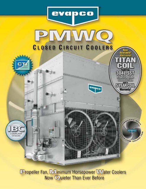
<strong>EVAPCO</strong> is Proud to Introduce<br />
Super Low Sound Technology<br />
for Forced Draft Axial Fan Closed<br />
Circuit Coolers.<br />
Super Low Sound Fan Technology<br />
• One Piece Molded Heavy Duty FRP Construction.<br />
• Sound level reduction 10-13 dBA on fan side @ 50’.<br />
<strong>PMWQ</strong>/LSWB Sound Comparisons<br />
Fan<br />
Sound Pressure Levels<br />
Opp.<br />
Motor Fan Opp. Fan<br />
Model No. Power End Side End Side Top<br />
LSWB 10-4M12 30 58 66 57 56 63<br />
<strong>PMWQ</strong> 10-5H12 15 57 66 57 57 62<br />
LSWB 10-4L18 50 59 66 59 56 63<br />
<strong>PMWQ</strong> 10-4I18 30 59 69 59 58 63<br />
NOTE: Sound pressure levels in dBA 50' from source.<br />
• Reduced energy consumption <strong>com</strong>pared to Forced Draft<br />
Centrifugal Closed Circuit Coolers.<br />
• Typical sound values equal or lower than Forced Draft<br />
Centrifugal Closed Circuit Coolers of similar size.<br />
Optional Pulse~Pure ®<br />
Water Treatment System<br />
Optional Platform and Ladder<br />
• Platform is self-supporting.<br />
• May be installed on either side of the unit.<br />
• Can be provided with an optional safety cage.<br />
• Control bacteria to levels well below traditional chemical water treatment.<br />
• Control the formation of mineral scale.<br />
• Save water by operating at higher cycles of concentration.<br />
• Yield corrosion rates equivalent to chemical water treatment.<br />
Stainless Steel Strainer<br />
• Superior resistance to corrosion.<br />
Optional<br />
Oversized Access Door<br />
• Man-sized door for easier unit access.<br />
• One sealed and gasketed door on<br />
each end of the unit.<br />
• Oversized Doors between each internal<br />
partition.
Tota ly Enclosed Pump Motors<br />
• Help assure long, trouble-free operation.<br />
Design and Construction Features<br />
Evapco’s NEW <strong>PMWQ</strong> units are the perfect option for installations that need it all – single-sided air inlet, low sound<br />
AND low horsepower. The new design includes Super Low Sound Fans as standard, allowing the <strong>PMWQ</strong> to operate<br />
at an average of 20-30% lower horsepower than similarly sized centrifugal models while also reducing sound levels<br />
†<br />
by 5-6 dBa. The <strong>PMWQ</strong> is designed to be IBC <strong>com</strong>plaint and have certified performance.<br />
CTI Certified † Efficient Drift Eliminators<br />
MOTOR AND DRIVE<br />
WA R R A N T Y<br />
Individual Fan Drive System<br />
• Increased flexibility for improved capacity control.<br />
• Greater reliability through redundancy.<br />
• Easy motor replacement.<br />
• Front mounted drives for improved<br />
maintenance accessibility.<br />
† Mark owned by the Cooling Technology Institute<br />
• Advanced design limits maximum drift rate.<br />
to 0.001% of circulated spray water rate.<br />
• Corrosion resistant PVC for long life.<br />
Zero Maintenance PVC Spray<br />
Distribution Header with<br />
ZMII ® Nozzles<br />
• Nozzles are threaded into header at<br />
proper orientation.<br />
• Fixed position nozzles require zero<br />
maintenance.<br />
• Large orifice nozzles prevent clogging.<br />
• Threaded end caps for ease of cleaning.<br />
Optional<br />
Featuring Thermal-Pak ® XT Construction<br />
• 304L SST Construction for Superior Corrosion Resistance.<br />
• 5 Year Extended Coil Warranty – STANDARD!!<br />
• Patented Thermal-Pak ® Introducing the Premier Closed Circuit Cooler<br />
Coil in the HVAC industry! The Titan provides:<br />
XT elliptical tube design with<br />
elliptical return bends and extra tough construction.<br />
Easy Field Assembly<br />
• Ensures easy assembly.<br />
• Incorporates self-guiding<br />
channels to guide the coil<br />
casing section into position<br />
improving the quality of the<br />
field seam.<br />
3<br />
®
4<br />
®<br />
What is IBC?<br />
International Building Code<br />
IBC COMPLIANCE<br />
In its continuing <strong>com</strong>mitment to be the leaders in evaporative cooling equipment design and services, <strong>EVAPCO</strong><br />
<strong>PMWQ</strong> Closed Circuit Coolers are now Independently Certified to withstand both Seismic and Wind Loads in<br />
ALL Geographic Locations and Installations in accordance with IBC 2006.<br />
The International Building Code (IBC) is a <strong>com</strong>prehensive set of<br />
regulations addressing both the structural design and the<br />
installation requirements for building systems – including<br />
HVAC and industrial refrigeration equipment. The IBC is<br />
intended to replace BOCA’s The National Building Code, ICBO’s<br />
Uniform Building Code and SBCCI’s Standard Building Code.<br />
Compared to previous building codes that considered only the<br />
building structure and <strong>com</strong>ponent anchorage, the requirements<br />
contained within the IBC address anchorage, structural<br />
integrity, and the operational capability of a <strong>com</strong>ponent<br />
following either a seismic or wind load event. Simply stated,<br />
the IBC code provisions require that evaporative cooling<br />
equipment, and all other <strong>com</strong>ponents permanently installed<br />
on a structure, must be designed to meet the same seismic<br />
and wind load forces as the building to which they are<br />
attached.<br />
How Does IBC 2006 Apply to Closed Circuit<br />
Coolers?<br />
Based on the project zip code and site design factors, calculations<br />
are made to determine the equivalent seismic “g force” and<br />
wind load (in pounds per square foot – psf) on the unit. The<br />
closed circuit cooler must be designed to withstand the greater<br />
of either the seismic or wind load.<br />
The New <strong>PMWQ</strong> is offered with a choice of TWO structural<br />
design packages:<br />
• Standard Structural Design – For projects with<br />
� 1.0g seismic or 145 psf wind loads<br />
• Upgraded Structural Design – Required for projects with<br />
> 1.0g seismic or 145 psf max wind loads<br />
More than 80% of the United States has design criteria<br />
resulting in a seismic design force of 1.0g or below. These<br />
sites will be provided with the standard <strong>PMWQ</strong> structural<br />
design. An upgraded structural design is available for<br />
installations with design criteria resulting in “g forces” greater<br />
than 1.0g. The highest “g force” location in North America is<br />
5.12g. The highest wind load shown on the maps is 170 mph,<br />
which is approximately equal to 145 psf velocity pressure.<br />
Therefore, the upgraded structural design package option for<br />
the New <strong>PMWQ</strong> is designed for 5.12g and 145 psf making it<br />
applicable to ALL building locations in North America.<br />
Seismic Design<br />
The attached chart from the US Geological Survey Website<br />
(http://www.usgs.gov/) shows the potential seismic activity in the<br />
United States. Buildings constructed in the red, orange and<br />
yellow areas of the map may require the upgraded <strong>PMWQ</strong><br />
construction design based on the site seismic design factors and<br />
should be reviewed closely. Critical use facilities, such as<br />
hospitals, are also more likely to require the upgraded design.<br />
Map courtesy US Geological Survey website<br />
Highest Hazard<br />
32+<br />
24-32<br />
16-24<br />
%g 8-16<br />
4-8<br />
2-4<br />
0-2<br />
Lowest Hazard<br />
The project architect or civil engineer is responsible for<br />
determining the seismic design factors to be used for the<br />
building design. A mechanical consulting engineer and/or design<br />
build contractor then applies these factors to a series of charts<br />
and graphs to determine the appropriate seismic design factors
ased on the location of the installation and ultimately the<br />
“importance” of the facility. The specific factors necessary for<br />
seismic design as well as a sample seismic calculation are<br />
available at www.evapco.<strong>com</strong>.<br />
Wind Design<br />
The IBC 2006 code book includes a map of basic wind speed (3second<br />
gust) by contour lines. However, local regulations may be<br />
more stringent than these published speeds. The specific factors<br />
necessary for wind load as well as a sample wind load calculation<br />
are available at www.evapco.<strong>com</strong>.<br />
Whichever design force - seismic or wind - is more severe for<br />
the building, governs the design of the building and all<br />
attached equipment.<br />
Wind Load Map Courtesy IBC 2006 Text –<br />
See full-sized map for location specific values<br />
Design Implementation<br />
<strong>EVAPCO</strong> applies the given seismic and wind load information<br />
provided by the mechanical consulting engineer to determine<br />
the equipment design necessary to meet IBC requirements.<br />
This process ensures that the mechanical equipment and its<br />
<strong>com</strong>ponents are <strong>com</strong>pliant per the provisions of the IBC as<br />
given in the plans and specifications for the project. For design<br />
build projects, <strong>EVAPCO</strong> is equipped to look up the information<br />
and submit the resulting loads for approval.<br />
Independent Certification<br />
Per the most recent edition of the code, the <strong>EVAPCO</strong> <strong>com</strong>pliance<br />
process included an exhaustive analysis by an independent<br />
approval<br />
agency. As<br />
required by the<br />
International<br />
Building Code,<br />
<strong>EVAPCO</strong> supplies<br />
a certificate<br />
of <strong>com</strong>pliance<br />
as part of<br />
its submittal<br />
documents.<br />
The certificate<br />
IBC COMPLIANCE<br />
Certificate of Compliance<br />
LSTB, LPT Cooling Towers<br />
<strong>PMWQ</strong>, LSW(A/B), LRW(B) Closed Circuit Coolers<br />
PMC-E, LSCB and LRC Evaporative Condensers<br />
Are certified to meet or exceed the Seismic and Wind Load Provisions<br />
set forth in the applicable building codes for this project.<br />
These products have been manufactured following all<br />
applicable quality assurance programs.<br />
Applicable Building Codes:<br />
IBC 2006<br />
ASCE-7<br />
NFPA 5000<br />
Referenced Report:<br />
VMA-43387<br />
Approval Agency:<br />
VMC Seismic Consulting Group<br />
<strong>EVAPCO</strong>...Specialists in Heat Transfer <strong>Product</strong>s and Services. FD IBC COC 001<br />
of <strong>com</strong>pliance demonstrates that the equipment has been independently<br />
tested and analyzed in accordance with the IBC seismic<br />
and wind load requirements. Evapco has worked closely<br />
with the independent approval agency to <strong>com</strong>plete the independent<br />
equipment testing and analysis.<br />
If the seismic “g force” and wind “psf” load requirements for<br />
the project site are known, <strong>EVAPCO</strong>’s online equipment selection<br />
software, iES, will allow you to choose the required structural<br />
design package – either standard construction or upgraded<br />
construction.<br />
If the project requirements are unknown, the following calculations<br />
must be <strong>com</strong>pleted.<br />
For further questions regarding IBC <strong>com</strong>pliance, please contact<br />
your local <strong>EVAPCO</strong> Representative or visit www.evapco.<strong>com</strong>.<br />
When using the <strong>EVAPCO</strong> selection software to make a<br />
selection, these calculations are already incorporated into the<br />
selection process. Simply enter the required seismic factors<br />
and the Seismic Design Force and Wind Load will be calculated<br />
automatically!!<br />
5<br />
®
6<br />
Principle of Operation<br />
DESIGN FEATURES<br />
The process fluid is circulated through the coil of the closed<br />
circuit cooler. Heat from the process fluid is dissipated through<br />
the coil tubes to the water cascading downward over the tubes.<br />
Simultaneously air is blown through the unit by the fans and<br />
travels upward over the coil opposite the water flow. A small<br />
portion of the water is evaporated which removes the heat. The<br />
warm moist air is forced to the top of the closed circuit cooler by<br />
the fan and is discharged to the atmosphere. The remaining water<br />
falls to the sump at the bottom of the cooler where it is<br />
recirculated by the pump up through the water distribution system<br />
and back down over the coils.<br />
Fluid In<br />
Fluid Out<br />
Cool Dry<br />
Entering Air<br />
®<br />
Hot Saturated<br />
Discharge Air<br />
Principle of Operation–Coolers<br />
<strong>EVAPCO</strong>AT Corrosion Protection System:<br />
G-235 Hot-Dip Galvanized Steel Construction<br />
The standard material of construction for evaporative cooling<br />
equipment for many years has been hot-dip galvanized steel. The<br />
purpose of galvanizing is to protect the base metal from corrosion,<br />
and the thickness of the galvanized layer directly affects the<br />
equipment life.<br />
<strong>EVAPCO</strong> has been instrumental in the development of corrosion<br />
protection technology and was the first manufacturer to use<br />
G-235 galvanized steel construction. The G-235 designation<br />
equates to a minimum of 2.35 ounces of zinc per square foot of<br />
surface area.<br />
The <strong>EVAPCO</strong>AT Corrosion Protection System is the heaviest<br />
galvanized coating available for extended corrosion protection<br />
eliminating the need for costly, unreliable epoxy paint finishes.<br />
Stainless Steel Material Options<br />
The <strong>PMWQ</strong> is available with an optional 304 or 316 stainless steel<br />
cold water basin or all stainless steel construction. For more information<br />
on these stainless steel options, see your local Evapco<br />
sales representative.<br />
Cooling Coil<br />
Evapco Closed Circuit Coolers utilize <strong>EVAPCO</strong>’s patented Thermal-<br />
Pak ® coil design which assures greater operating efficiency. The<br />
elliptical tube design allows for closer tube spacing, resulting in<br />
greater surface area per plan area than round-tube coil designs. In<br />
addition, the Thermal-Pak ® design has lower resistance to airflow<br />
and also permits greater water loading, making the Thermal-Pak ®<br />
coil the most effective design available.<br />
The coils are manufactured from high quality steel tubing following<br />
the most stringent quality control procedures. Each circuit is<br />
inspected to ensure the material quality and then tested before<br />
being assembled into a coil. Finally, the assembled coil is pneumatically<br />
tested at 400 psig under water to ensure it is leak free.<br />
To protect the coil against corrosion, it is placed in a heavy steel<br />
frame and then the entire assembly is dipped in molten zinc (hotdip<br />
galvanized) at a temperature of approximately 800°F.<br />
Thermal-Pak ® Coil by <strong>EVAPCO</strong><br />
Round Tube Coil by Others<br />
Note: Closed circuit coolers with galvanized coils should only be<br />
used on sealed, pressurized systems. Continual aeration of the<br />
water in an open system can cause corrosion inside the tubes of<br />
the cooler leading to premature failure.<br />
U.S. Patent # 5,799,725
Stainless Steel Coil Option<br />
NOW Evapco offers the optional .<br />
Constructed with type 304L Stainless Steel, the TITAN COIL is<br />
manufactured using Evapco’s patented elliptical tube Thermal Pak ®<br />
design upgraded to Xtra Tough construction featuring: Xtra<br />
Durability, Xtra Corrosion Resistance, and an Xtra long 5 YEAR<br />
Coil Warranty as standard.<br />
U.S. Patent No. 5,799,725<br />
Maintenance Free ZMII ® Spray Nozzle<br />
Water Distribution System<br />
<strong>EVAPCO</strong>’S Zero Maintenance ZMII ® Spray Nozzle<br />
remains clog-free while providing even and<br />
constant water distribution for reliable, scale-free<br />
evaporative cooling under all operating conditions.<br />
The heavy duty nylon ZMII ® Spray nozzles have a<br />
1-5/16” diameter opening and a 1-1/2” splash plate<br />
clearance. Furthermore, the fixed position ZMII ®<br />
nozzles are mounted in corrosion-free PVC water<br />
ZMII<br />
distribution pipes that have threaded end caps.<br />
Together, these elements <strong>com</strong>bine to provide unequaled coil coverage<br />
and scale prevention, and make the industry’s best performing<br />
non-corrosive, maintenance-free water distribution system.<br />
® Nozzle<br />
Efficient Drift Eliminators<br />
The <strong>PMWQ</strong> is provided with an efficient drift eliminator system that<br />
effectively reduces entrained water droplets from the air discharge to<br />
less than 0.001% of the spray water flow rate.<br />
The eliminators are constructed of non-corrosive PVC with a multipass<br />
design for maximum drift reduction. They are assembled in<br />
modular sections for easy<br />
removal and access to the<br />
water distribution system.<br />
In addition to reducing drift,<br />
the eliminators also<br />
function as effective debris<br />
screens which protect the<br />
spray system from sunlight<br />
and debris.<br />
<strong>PMWQ</strong> Drift Eliminator<br />
Thermal-Pak ® Coil<br />
DESIGN FEATURES<br />
Individual Fan Drive System<br />
The new <strong>PMWQ</strong> fan drive system provides individual motor to fan<br />
configuration as standard equipment on all models. The dedicated<br />
fan to motor arrangement ensures less “wear & tear” on the drive<br />
system versus tandem fan motor drive arrangements resulting in<br />
less maintenance.<br />
Fan Drive Accessibility<br />
The drive <strong>com</strong>ponents of the <strong>PMWQ</strong> are easily accessed for routine<br />
maintenance from the front of the unit. Bearing grease fittings are<br />
extended to the outside of the unit for ease of lubrication. All drive<br />
sheaves have been relocated to the front of the fan section and<br />
motors are positioned on a platform base to allow for easy belt<br />
tension adjustment.<br />
Easy Clean Sloped Basin & Man-Sized<br />
Access Doors<br />
The <strong>PMWQ</strong> drain pan is designed<br />
to improve maintenance access<br />
and make it easier for operating<br />
technicians to clean. The bottom<br />
of the pan is sloped to the unit<br />
drain to ensure that the basin will<br />
<strong>com</strong>pletely drain and allow<br />
sediment and debris that may<br />
collect in the basin to be easily<br />
flushed from the unit. The design<br />
helps to prevent buildup of<br />
sedimentary deposits, biological<br />
films and standing water.<br />
Evapco also offers optional<br />
“man-sized” access doors to<br />
improve access to this critical<br />
area of the unit.<br />
7<br />
®
8<br />
30-3/8"<br />
(772)<br />
®<br />
Engineering Data & Dimensions<br />
<strong>PMWQ</strong> Models 10-3G12 to 10-7J12<br />
U<br />
ROUND<br />
ACCESS<br />
DOORS<br />
3(80) MPT<br />
DRAIN<br />
57"<br />
(1448)<br />
(2) 4 (100) BFW FLUID IN<br />
(2) 4 (100) BFW FLUID OUT<br />
9' 9-3/4"<br />
(2991)<br />
2(50) MPT<br />
MAKE UP<br />
3(80) FPT<br />
OVERFLOW<br />
8' 7-1/4"<br />
(2623)<br />
A<br />
9' 11"<br />
(3022)<br />
1 Model Number will end in “-Z” for units with Series Flow piping configuration. Series Flow units will require crossover piping. Model numbers will include "C" for units with Stainless Steel<br />
coil(s) and "S" for units with an option that negates CTI certification.<br />
2 Heaviest section is the coil section.<br />
3 Gallons shown is water in suspension in unit and piping. Allow for additional water in bottom of remote sump to cover pump suction and strainer during operation (12” would normally be<br />
sufficient).<br />
4 When a remote sump arrangement is selected, the spray pump, suction strainer and associated piping are omitted; the unit is provided with an oversized outlet to facilitate drainage to the<br />
remote sump.<br />
5 Unit dimensions and coil connections may vary slightly from catalog. See factory certified prints for dimensions, quantity of coil connections, and piping configuration. Coil connections are<br />
4” bevel for weld (BFW). Other connection types such as grooved for mechanical coupling or flanged are also available as options.<br />
H<br />
18"<br />
(457)<br />
(2) 1/2 FPT VENT<br />
11' 11-3/4"<br />
(3652)<br />
Note: The number of coil connections doubles when the flow rate exceeds 900 gm on 10x12 models. This required option is referred to as the High Flow coil configuration.<br />
Coil<br />
<strong>PMWQ</strong> Heaviest Volume Gallons Conn. Operating Height Upper Coil<br />
Model Number 1 Shipping Section 2 Operating HP CFM HP GPM (Gallons) Required 3 Weights (lbs.) Fans Spray Pump Remote Sump<br />
Size Weight (lbs.) H U A<br />
10-3G12 13,350 8,590 17,430 (2) 5 54,300 5 685 253 500 10" 16,750 13' 7-3/8" 5' 1" 22-1/4"<br />
10-3H12 13,460 8,590 17,540 (2) 7.5 62,300 5 685 253 500 10" 16,860 13' 7-3/8" 5' 1" 22-1/4"<br />
10-3I12 13,490 8,590 17,570 (2) 10 68,700 5 685 253 500 10" 16,890 13' 7-3/8" 5' 1" 22-1/4"<br />
10-3J12 13,750 8,590 17,830 (2) 15 78,900 5 685 253 500 10" 17,150 13' 7-3/8" 5' 1" 22-1/4"<br />
10-4G12 15,320 10,560 19,480 (2) 5 53,500 5 685 332 500 10" 18,800 14' 3-7/8" 5' 9-1/2" 30-3/4"<br />
10-4H12 15,430 10,560 19,590 (2) 7.5 61,400 5 685 332 500 10" 18,910 14' 3-7/8" 5' 9-1/2" 30-3/4"<br />
10-4I12 15,460 10,560 19,620 (2) 10 67,600 5 685 332 500 10" 18,940 14' 3-7/8" 5' 9-1/2" 30-3/4"<br />
10-4J12 15,720 10,560 19,880 (2) 15 77,800 5 685 332 500 10" 19,200 14' 3-7/8" 5' 9-1/2" 30-3/4"<br />
10-5G12 17,180 12,420 21,420 (2) 5 52,700 5 685 411 500 10" 20,740 15' 3/8" 6' 6" 39-1/4"<br />
10-5H12 17,290 12,420 21,530 (2) 7.5 60,400 5 685 411 500 10" 20,850 15' 3/8" 6' 6" 39-1/4"<br />
10-5I12 17,320 12,420 21,560 (2) 10 66,700 5 685 411 500 10" 20,880 15' 3/8" 6' 6" 39-1/4"<br />
10-5J12 17,580 12,420 21,820 (2) 15 76,600 5 685 411 500 10" 21,140 15' 3/8" 6' 6" 39-1/4"<br />
10-6G12 19,130 14,370 23,440 (2) 5 52,000 5 685 490 500 10" 22,760 15' 8-7/8" 7' 2-1/2" 47-3/4"<br />
10-6H12 19,240 14,370 23,550 (2) 7.5 59,500 5 685 490 500 10" 22,870 15' 8-7/8" 7' 2-1/2" 47-3/4"<br />
10-6I12 19,270 14,370 23,580 (2) 10 65,700 5 685 490 500 10" 22,900 15' 8-7/8" 7' 2-1/2" 47-3/4"<br />
10-6J12 19,530 14,370 23,840 (2) 15 75,500 5 685 490 500 10" 23,160 15' 8-7/8" 7' 2-1/2" 47-3/4"<br />
10-7G12 21,480 16,720 25,870 (2) 5 51,200 5 685 569 500 10" 25,190 15' 8-7/8" 7' 2-1/2" 47-3/4"<br />
10-7H12 21,590 16,720 25,980 (2) 7.5 58,600 5 685 569 500 10" 25,300 15' 8-7/8" 7' 2-1/2" 47-3/4"<br />
10-7I12 21,620 16,720 26,010 (2) 10 64,700 5 685 569 500 10" 25,330 15' 8-7/8" 7' 2-1/2" 47-3/4"<br />
10-7J12 21,880 16,720 26,270 (2) 15 74,400 5 685 569 500 10" 25,590 15' 8-7/8" 7' 2-1/2" 47-3/4"<br />
4 Dimensions 5
Selections for <strong>PMWQ</strong> Closed Circuit Coolers are available from Evapco’s iES Equipment Selection Program.<br />
Please contact your local sales representative for more information on the iES program.<br />
Engineering Data & Dimensions<br />
<strong>PMWQ</strong> Models 10-3G18 to 10-7J18<br />
30-3/8"<br />
(772)<br />
U<br />
ROUND<br />
ACCESS<br />
DOORS<br />
3(80) MPT<br />
DRAIN<br />
57"<br />
(1448)<br />
(2) 4 (100) BFW FLUID IN<br />
(2) 4 (100) BFW FLUID OUT<br />
9' 9-3/4"<br />
(2991)<br />
2(50) MPT<br />
MAKE UP<br />
3(80) FPT<br />
OVERFLOW<br />
8' 7-1/4"<br />
(2623)<br />
A<br />
9' 11"<br />
(3022)<br />
H<br />
20-5/8"<br />
(524)<br />
(2) 1/2 FPT VENT<br />
Note: The number of coil connections doubles when the flow rate exceeds 900 gm on 10x18 models. This required option is referred to as the High Flow coil configuration.<br />
Coil<br />
<strong>PMWQ</strong> Heaviest Volume Gallons Conn. Operating Height Upper Coil<br />
Model Number 1 Shipping Section 2 Operating HP CFM HP GPM (Gallons) Required 3 Weights (lbs.) Fans Spray Pump Remote Sump<br />
Size Weight (lbs.) H U A<br />
10-3G18 20,320 12,580 26,640 (3) 5 81,700 7.5 1,030 374 620 12" 24,440 13' 7-3/8" 5' 1" 22-1/4"<br />
10-3H18 20,480 12,580 26,800 (3) 7.5 93,700 7.5 1,030 374 620 12" 24,600 13' 7-3/8" 5' 1" 22-1/4"<br />
10-3I18 20,530 12,580 26,850 (3) 10 103,300 7.5 1,030 374 620 12" 24,650 13' 7-3/8" 5' 1" 22-1/4"<br />
10-3J18 20,920 12,580 27,240 (3) 15 118,800 7.5 1,030 374 620 12" 25,040 13' 7-3/8" 5' 1" 22-1/4"<br />
10-4G18 23,250 15,510 29,690 (3) 5 80,500 7.5 1,030 494 620 12" 27,490 14' 3-7/8" 5' 9-1/2" 30-3/4"<br />
10-4H18 23,410 15,510 29,850 (3) 7.5 92,400 7.5 1,030 494 620 12" 27,650 14' 3-7/8" 5' 9-1/2" 30-3/4"<br />
10-4I18 23,460 15,510 29,900 (3) 10 101,800 7.5 1,030 494 620 12" 27,700 14' 3-7/8" 5' 9-1/2" 30-3/4"<br />
10-4J18 23,850 15,510 30,290 (3) 15 117,000 7.5 1,030 494 620 12" 28,090 14' 3-7/8" 5' 9-1/2" 30-3/4"<br />
10-5G18 26,070 18,330 32,620 (3) 5 79,300 7.5 1,030 613 620 12" 30,420 15' 3/8" 6' 6" 39-1/4"<br />
10-5H18 26,230 18,330 32,780 (3) 7.5 91,000 7.5 1,030 613 620 12" 30,580 15' 3/8" 6' 6" 39-1/4"<br />
10-5I18 26,280 18,330 32,830 (3) 10 100,300 7.5 1,030 613 620 12" 30,630 15' 3/8" 6' 6" 39-1/4"<br />
10-5J18 26,670 18,330 33,220 (3) 15 115,300 7.5 1,030 613 620 12" 31,020 15' 3/8" 6' 6" 39-1/4"<br />
10-6G18 29,000 21,260 35,670 (3) 5 78,100 7.5 1,030 732 620 12" 33,470 15' 8-7/8" 7' 2-1/2" 47-3/4"<br />
10-6H18 29,160 21,260 35,830 (3) 7.5 89,600 7.5 1,030 732 620 12" 33,630 15' 8-7/8" 7' 2-1/2" 47-3/4"<br />
10-6I18 29,210 21,260 35,880 (3) 10 98,900 7.5 1,030 732 620 12" 33,680 15' 8-7/8" 7' 2-1/2" 47-3/4"<br />
10-6J18 29,600 21,260 36,270 (3) 15 113,600 7.5 1,030 732 620 12" 34,070 15' 8-7/8" 7' 2-1/2" 47-3/4"<br />
10-7G18 32,530 24,790 39,320 (3) 5 76,900 7.5 1,030 851 620 12" 37,120 15' 8-7/8" 7' 2-1/2" 47-3/4"<br />
10-7H18 32,690 24,790 39,480 (3) 7.5 88,300 7.5 1,030 851 620 12" 37,280 15' 8-7/8" 7' 2-1/2" 47-3/4"<br />
10-7I18 32,740 24,790 39,530 (3) 10 97,400 7.5 1,030 851 620 12" 37,330 15' 8-7/8" 7' 2-1/2" 47-3/4"<br />
10-7J18 33,130 24,790 39,920 (3) 15 111,900 7.5 1,030 851 620 12" 37,720 15' 8-7/8" 7' 2-1/2" 47-3/4"<br />
4 Dimensions 5<br />
1 Model Number will end in “-Z” for units with Series Flow piping configuration. Series Flow units will require crossover piping. Model numbers will include "C" for units with Stainless Steel<br />
coil(s) and "S" for units with an option that negates CTI certification.<br />
2 Heaviest section is the coil section.<br />
3 Gallons shown is water in suspension in unit and piping. Allow for additional water in bottom of remote sump to cover pump suction and strainer during operation (12” would normally be<br />
sufficient).<br />
4 When a remote sump arrangement is selected, the spray pump, suction strainer and associated piping are omitted; the unit is provided with an oversized outlet to facilitate drainage to the<br />
remote sump.<br />
5 Unit dimensions and coil connections may vary slightly from catalog. See factory certified prints for dimensions, quantity of coil connections, and piping configuration. Coil connections are<br />
4” bevel for weld (BFW). Other connection types such as grooved for mechanical coupling or flanged are also available as options.<br />
18' 1/8"<br />
(5490)<br />
9<br />
®
30-3/8"<br />
(772)<br />
3(80) MPT<br />
DRAIN<br />
®<br />
Engineering Data & Dimensions<br />
<strong>PMWQ</strong> Models 10-3G24 to 10-7J24<br />
10<br />
U<br />
57"<br />
(1448)<br />
(4) 4 (100) BFW FLUID IN<br />
(4) 4 (100) BFW FLUID OUT<br />
ROUND<br />
ACCESS<br />
DOORS<br />
2(50) MPT<br />
MAKE UP<br />
8' 7-1/4"<br />
(2633)<br />
9' 9-3/4"<br />
(2991)<br />
3(80) FPT<br />
OVERFLOW<br />
A<br />
H<br />
9' 11"<br />
(3022)<br />
18"<br />
(457)<br />
(2) 1/2 FPT VENT (2) 1/2 FPT VENT<br />
Note: The number of coil connections doubles when the flow rate exceeds 1800 gm on 10x24 models. This required option is referred to as the High Flow coil configuration.<br />
Coil<br />
<strong>PMWQ</strong> Heaviest Volume Gallons Conn. Operating Height Upper Coil<br />
Model Number 1 Shipping Section 2 Operating HP CFM HP GPM (Gallons) Required 3 Weights (lbs.) Fans Spray Pump Remote Sump<br />
Size Weight (lbs.) H U A<br />
10-3G24 26,770 10190* 35,300 (4) 5 108,600 (2) 5 1,370 507 930 12" 33,160 13' 7-3/8" 5' 1" 22-1/4"<br />
10-3H24 26,980 10400* 35,510 (4) 7.5 124,600 (2) 5 1,370 507 930 12" 33,370 13' 7-3/8" 5' 1" 22-1/4"<br />
10-3I24 27,040 10460* 35,570 (4) 10 137,400 (2) 5 1,370 507 930 12" 33,430 13' 7-3/8" 5' 1" 22-1/4"<br />
10-3J24 27,570 10990* 36,100 (4) 15 157,800 (2) 5 1,370 507 930 12" 33,960 13' 7-3/8" 5' 1" 22-1/4"<br />
10-4G24 30,910 10,360 39,590 (4) 5 107,000 (2) 5 1,370 664 930 12" 37,450 14' 3-7/8" 5' 9-1/2" 30-3/4"<br />
10-4H24 31,120 10400* 39,800 (4) 7.5 122,800 (2) 5 1,370 664 930 12" 37,660 14' 3-7/8" 5' 9-1/2" 30-3/4"<br />
10-4I24 31,180 10460* 39,860 (4) 10 135,200 (2) 5 1,370 664 930 12" 37,720 14' 3-7/8" 5' 9-1/2" 30-3/4"<br />
10-4J24 31,710 10990* 40,390 (4) 15 155,600 (2) 5 1,370 664 930 12" 38,250 14' 3-7/8" 5' 9-1/2" 30-3/4"<br />
10-5G24 34,830 12,320 43,670 (4) 5 105,400 (2) 5 1,370 822 930 12" 41,530 15' 3/8" 6' 6" 39-1/4"<br />
10-5H24 35,040 12,320 43,880 (4) 7.5 120,800 (2) 5 1,370 822 930 12" 41,740 15' 3/8" 6' 6" 39-1/4"<br />
10-5I24 35,100 12,320 43,940 (4) 10 133,400 (2) 5 1,370 822 930 12" 41,800 15' 3/8" 6' 6" 39-1/4"<br />
10-5J24 35,630 12,320 44,470 (4) 15 153,200 (2) 5 1,370 822 930 12" 42,330 15' 3/8" 6' 6" 39-1/4"<br />
10-6G24 38,930 14,370 47,920 (4) 5 104,000 (2) 5 1,370 980 930 12" 45,780 15' 8-7/8" 7' 2-1/2" 47-3/4"<br />
10-6H24 39,140 14,370 48,130 (4) 7.5 119,000 (2) 5 1,370 980 930 12" 45,990 15' 8-7/8" 7' 2-1/2" 47-3/4"<br />
10-6I24 39,200 14,370 48,190 (4) 10 131,400 (2) 5 1,370 980 930 12" 46,050 15' 8-7/8" 7' 2-1/2" 47-3/4"<br />
10-6J24 39,730 14,370 48,720 (4) 15 151,000 (2) 5 1,370 980 930 12" 46,580 15' 8-7/8" 7' 2-1/2" 47-3/4"<br />
10-7G24 43,630 16,720 52,780 (4) 5 102,400 (2) 5 1,370 1,138 930 12" 50,640 15' 8-7/8" 7' 2-1/2" 47-3/4"<br />
10-7H24 43,840 16,720 52,990 (4) 7.5 117,200 (2) 5 1,370 1,138 930 12" 50,850 15' 8-7/8" 7' 2-1/2" 47-3/4"<br />
10-7I24 43,900 16,720 53,050 (4) 10 129,400 (2) 5 1,370 1,138 930 12" 50,910 15' 8-7/8" 7' 2-1/2" 47-3/4"<br />
10-7J24 44,430 16,720 53,580 (4) 15 148,800 (2) 5 1,370 1,138 930 12" 51,440 15' 8-7/8" 7' 2-1/2" 47-3/4"<br />
4 Dimensions 5<br />
1 Model Number will end in “-Z” for units with Series Flow piping configuration. Series Flow units will require crossover piping. Model numbers will include "C" for units with Stainless Steel<br />
coil(s) and "S" for units with an option that negates CTI certification.<br />
2 Heaviest section is the coil section except for units designated with a *. Heaviest section is the basin section for units designated with a *.<br />
3 Gallons shown is water in suspension in unit and piping. Allow for additional water in bottom of remote sump to cover pump suction and strainer during operation (12” would normally be<br />
sufficient).<br />
4 When a remote sump arrangement is selected, the spray pump, suction strainer and associated piping are omitted; the unit is provided with an oversized outlet to facilitate drainage to the<br />
remote sump.<br />
5 Unit dimensions and coil connections may vary slightly from catalog. See factory certified prints for dimensions, quantity of coil connections, and piping configuration. Coil connections are<br />
4” bevel for weld (BFW). Other connection types such as grooved for mechanical coupling or flanged are also available as options.<br />
24' 7/8"<br />
(7339)<br />
16-3/8"<br />
(416)
Selections for <strong>PMWQ</strong> Closed Circuit Coolers are available from Evapco’s iES Equipment Selection Program.<br />
Please contact your local sales representative for more information on the iES program.<br />
Engineering Data & Dimensions<br />
<strong>PMWQ</strong> Models 10-3G36<br />
to 10-7J36<br />
30-3/8"<br />
(772)<br />
3(80) MPT<br />
DRAIN<br />
57"<br />
(1448)<br />
U (4) 4 (100) BFW FLUID IN<br />
(4) 4 (100) BFW FLUID OUT<br />
ROUND<br />
ACCESS<br />
DOORS<br />
9' 9-3/4"<br />
(2991)<br />
2(50) MPT<br />
MAKE UP<br />
3(80) FPT<br />
OVERFLOW<br />
8' 7-1/4"<br />
(2623)<br />
A<br />
9' 11"<br />
(3022)<br />
H<br />
20-5/8"<br />
(524)<br />
(2) 1/2 FPT VENT (2) 1/2 FPT VENT<br />
36' 2"<br />
(11024)<br />
Note: The number of coil connections doubles when the flow rate exceeds 1800 gm on 10x36 models. This required option is referred to as the High Flow coil configuration.<br />
Coil<br />
<strong>PMWQ</strong> Heaviest Volume Gallons Conn. Operating Height Upper Coil<br />
Model Number 1 Shipping Section 2 Operating HP CFM HP GPM (Gallons) Required 3 Weights (lbs.) Fans Spray Pump Remote Sump<br />
Size Weight (lbs.) H U A<br />
10-3G36 39,140 14740* 52,110 (6) 5 163,400 (2) 7.5 2,060 748 1,400 14" 48,830 13' 7-3/8" 5' 1" 22-1/4"<br />
10-3H36 39,450 15050* 52,420 (6) 7.5 187,400 (2) 7.5 2,060 748 1,400 14" 49,140 13' 7-3/8" 5' 1" 22-1/4"<br />
10-3I36 39,550 15150* 52,520 (6) 10 206,600 (2) 7.5 2,060 748 1,400 14" 49,240 13' 7-3/8" 5' 1" 22-1/4"<br />
10-3J36 40,330 15930* 53,300 (6) 15 237,600 (2) 7.5 2,060 748 1,400 14" 50,020 13' 7-3/8" 5' 1" 22-1/4"<br />
10-4G36 45,260 15,260 58,460 (6) 5 161,000 (2) 7.5 2,060 987 1,400 14" 55,190 14' 3-7/8" 5' 9-1/2" 30-3/4"<br />
10-4H36 45,570 15,260 58,770 (6) 7.5 184,800 (2) 7.5 2,060 987 1,400 14" 55,500 14' 3-7/8" 5' 9-1/2" 30-3/4"<br />
10-4I36 45,670 15,260 58,870 (6) 10 203,600 (2) 7.5 2,060 987 1,400 14" 55,600 14' 3-7/8" 5' 9-1/2" 30-3/4"<br />
10-4J36 46,450 15930* 59,650 (6) 15 234,000 (2) 7.5 2,060 987 1,400 14" 56,380 14' 3-7/8" 5' 9-1/2" 30-3/4"<br />
10-5G36 51,160 18,210 64,600 (6) 5 158,600 (2) 7.5 2,060 1,226 1,400 14" 61,320 15' 3/8" 6' 6" 39-1/4"<br />
10-5H36 51,470 18,210 64,910 (6) 7.5 182,000 (2) 7.5 2,060 1,226 1,400 14" 61,630 15' 3/8" 6' 6" 39-1/4"<br />
10-5I36 51,570 18,210 65,010 (6) 10 200,600 (2) 7.5 2,060 1,226 1,400 14" 61,730 15' 3/8" 6' 6" 39-1/4"<br />
10-5J36 52,350 18,210 65,790 (6) 15 230,600 (2) 7.5 2,060 1,226 1,400 14" 62,510 15' 3/8" 6' 6" 39-1/4"<br />
10-6G36 57,260 21,260 70,930 (6) 5 156,200 (2) 7.5 2,060 1,464 1,400 14" 67,650 15' 8-7/8" 7' 2-1/2" 47-3/4"<br />
10-6H36 57,570 21,260 71,240 (6) 7.5 179,200 (2) 7.5 2,060 1,464 1,400 14" 67,960 15' 8-7/8" 7' 2-1/2" 47-3/4"<br />
10-6I36 57,670 21,260 71,340 (6) 10 197,800 (2) 7.5 2,060 1,464 1,400 14" 68,060 15' 8-7/8" 7' 2-1/2" 47-3/4"<br />
10-6J36 58,450 21,260 72,120 (6) 15 227,200 (2) 7.5 2,060 1,464 1,400 14" 68,840 15' 8-7/8" 7' 2-1/2" 47-3/4"<br />
10-7G36 64,320 24,790 78,220 (6) 5 153,800 (2) 7.5 2,060 1,703 1,400 14" 74,950 15' 8-7/8" 7' 2-1/2" 47-3/4"<br />
10-7H36 64,630 24,790 78,530 (6) 7.5 176,600 (2) 7.5 2,060 1,703 1,400 14" 75,260 15' 8-7/8" 7' 2-1/2" 47-3/4"<br />
10-7I36 64,730 24,790 78,630 (6) 10 194,800 (2) 7.5 2,060 1,703 1,400 14" 75,360 15' 8-7/8" 7' 2-1/2" 47-3/4"<br />
10-7J36 65,510 24,790 79,410 (6) 15 223,800 (2) 7.5 2,060 1,703 1,400 14" 76,140 15' 8-7/8" 7' 2-1/2" 47-3/4"<br />
4 Dimensions 5<br />
1 Model Number will end in “-Z” for units with Series Flow piping configuration. Series Flow units will require crossover piping. Model numbers will include "C" for units with Stainless Steel<br />
coil(s) and "S" for units with an option that negates CTI certification.<br />
2 Heaviest section is the coil section except for units designated with a *. Heaviest section is the basin section for units designated with a *.<br />
3 Gallons shown is water in suspension in unit and piping. Allow for additional water in bottom of remote sump to cover pump suction and strainer during operation (12” would normally be<br />
sufficient).<br />
4 When a remote sump arrangement is selected, the spray pump, suction strainer and associated piping are omitted; the unit is provided with an oversized outlet to facilitate drainage to the<br />
remote sump.<br />
5 Unit dimensions and coil connections may vary slightly from catalog. See factory certified prints for dimensions, quantity of coil connections, and piping configuration. Coil connections are<br />
4” bevel for weld (BFW). Other connection types such as grooved for mechanical coupling or flanged are also available as options.<br />
23-5/8"<br />
(600)<br />
11<br />
®
36-3/4"<br />
(933)<br />
®<br />
Engineering Data & Dimensions<br />
<strong>PMWQ</strong> Models 12-3G12 to 12-7J12<br />
12<br />
3(80) MPT<br />
DRAIN<br />
68-5/8"<br />
(1743)<br />
U<br />
(2)4 (100) BFW FLUID IN<br />
A<br />
(2)4 (100) BFW FLUID OUT<br />
OVERSIZED<br />
ACCESS<br />
DOORS<br />
2(50) MPT<br />
MAKE UP<br />
8' 7-11/16"<br />
(2634)<br />
11' 10-3/8"<br />
(3618)<br />
3(80) FPT<br />
OVERFLOW<br />
9' 11"<br />
(3023)<br />
H<br />
18"<br />
(457)<br />
(2) 1/2 FPT VENT<br />
11' 11-3/4"<br />
(3652)<br />
Note: The number of coil connections doubles when the flow rate exceeds 900 gm on 12x12 models. This required option is referred to as the High Flow coil configuration.<br />
Coil<br />
<strong>PMWQ</strong> Heaviest Volume Gallons Conn. Operating Height Upper Coil<br />
Model Number 1 Shipping Section 2 Operating HP CFM HP GPM (Gallons) Required 3 Weights (lbs.) Fans Spray Pump Remote Sump<br />
Size Weight (lbs.) H U A<br />
12-3G12 15,440 9,970 20,480 (2) 5 65,000 5 800 312 570 10" 19,450 13' 7-3/8" 5' 1" 22-1/4"<br />
12-3H12 15,540 9,970 20,580 (2) 7.5 74,400 5 800 312 570 10" 19,550 13' 7-3/8" 5' 1" 22-1/4"<br />
12-3I12 15,570 9,970 20,610 (2) 10 79,400 5 800 312 570 10" 19,580 13' 7-3/8" 5' 1" 22-1/4"<br />
12-3J12 15,840 9,970 20,880 (2) 15 91,300 5 800 312 570 10" 19,850 13' 7-3/8" 5' 1" 22-1/4"<br />
12-4G12 17,830 12,360 22,970 (2) 5 64,000 5 800 409 570 10" 21,940 14' 3-7/8" 5' 9-1/2" 30-3/4"<br />
12-4H12 17,930 12,360 23,070 (2) 7.5 73,300 5 800 409 570 10" 22,040 14' 3-7/8" 5' 9-1/2" 30-3/4"<br />
12-4I12 17,960 12,360 23,100 (2) 10 78,200 5 800 409 570 10" 22,070 14' 3-7/8" 5' 9-1/2" 30-3/4"<br />
12-4J12 18,230 12,360 23,370 (2) 15 89,900 5 800 409 570 10" 22,340 14' 3-7/8" 5' 9-1/2" 30-3/4"<br />
12-5G12 20,100 14,630 25,330 (2) 5 63,300 5 800 506 570 10" 24,300 15' 3/8" 6' 6" 39-1/4"<br />
12-5H12 20,200 14,630 25,430 (2) 7.5 72,400 5 800 506 570 10" 24,400 15' 3/8" 6' 6" 39-1/4"<br />
12-5I12 20,230 14,630 25,460 (2) 10 77,100 5 800 506 570 10" 24,430 15' 3/8" 6' 6" 39-1/4"<br />
12-5J12 20,500 14,630 25,730 (2) 15 88,700 5 800 506 570 10" 24,700 15' 3/8" 6' 6" 39-1/4"<br />
12-6G12 22,330 16,860 27,660 (2) 5 62,200 5 800 604 570 10" 26,630 15' 8-7/8" 7' 2-1/2" 47-3/4"<br />
12-6H12 22,430 16,860 27,760 (2) 7.5 71,200 5 800 604 570 10" 26,730 15' 8-7/8" 7' 2-1/2" 47-3/4"<br />
12-6I12 22,460 16,860 27,790 (2) 10 76,000 5 800 604 570 10" 26,760 15' 8-7/8" 7' 2-1/2" 47-3/4"<br />
12-6J12 22,730 16,860 28,060 (2) 15 87,200 5 800 604 570 10" 27,030 15' 8-7/8" 7' 2-1/2" 47-3/4"<br />
12-7G12 25,090 19,620 30,520 (2) 5 61,200 5 800 701 570 10" 29,490 15' 8-7/8" 7' 2-1/2" 47-3/4"<br />
12-7H12 25,190 19,620 30,620 (2) 7.5 70,100 5 800 701 570 10" 29,590 15' 8-7/8" 7' 2-1/2" 47-3/4"<br />
12-7I12 25,220 19,620 30,650 (2) 10 74,900 5 800 701 570 10" 29,620 15' 8-7/8" 7' 2-1/2" 47-3/4"<br />
12-7J12 25,490 19,620 30,920 (2) 15 85,900 5 800 701 570 10" 29,890 15' 8-7/8" 7' 2-1/2" 47-3/4"<br />
4 Dimensions 5<br />
1 Model Number will end in “-Z” for units with Series Flow piping configuration. Series Flow units will require crossover piping. Model numbers will include "C" for units with Stainless Steel<br />
coil(s) and "S" for units with an option that negates CTI certification.<br />
2 Heaviest section is the coil section.<br />
3 Gallons shown is water in suspension in unit and piping. Allow for additional water in bottom of remote sump to cover pump suction and strainer during operation (12” would normally be<br />
sufficient).<br />
4 When a remote sump arrangement is selected, the spray pump, suction strainer and associated piping are omitted; the unit is provided with an oversized outlet to facilitate drainage to the<br />
remote sump.<br />
5 Unit dimensions and coil connections may vary slightly from catalog. See factory certified prints for dimensions, quantity of coil connections, and piping configuration. Coil connections are<br />
4” bevel for weld (BFW). Other connection types such as grooved for mechanical coupling or flanged are also available as options.
Selections for <strong>PMWQ</strong> Closed Circuit Coolers are available from Evapco’s iES Equipment Selection Program.<br />
Please contact your local sales representative for more information on the iES program.<br />
Engineering Data & Dimensions<br />
<strong>PMWQ</strong> Models 12-3G18 to 12-7J18<br />
36-3/4"<br />
(933)<br />
U<br />
ROUND<br />
ACCESS<br />
DOORS<br />
3(80) MPT<br />
DRAIN<br />
68-5/8"<br />
(1743)<br />
(2) 4 (100) BFW FLUID IN<br />
(2) 4 (100) BFW FLUID OUT<br />
11' 10-3/8"<br />
(3618)<br />
2(50) MPT<br />
MAKE UP<br />
3(80) FPT<br />
OVERFLOW<br />
8' 7-11/16"<br />
(2634)<br />
A<br />
9' 11"<br />
(3023)<br />
H<br />
20-5/8"<br />
(524)<br />
(2) 1/2 FPT VENT<br />
Note: The number of coil connections doubles when the flow rate exceeds 900 gm on 12x18 models. This required option is referred to as the High Flow coil configuration.<br />
Coil<br />
<strong>PMWQ</strong> Heaviest Volume Gallons Conn. Operating Height Upper Coil<br />
Model Number 1 Shipping Section 2 Operating HP CFM HP GPM (Gallons) Required 3 Weights (lbs.) Fans Spray Pump Remote Sump<br />
Size Weight (lbs.) H U A<br />
12-3G18 23,490 14,920 30,820 (3) 5 97,200 7.5 1,200 461 740 12" 28,160 13' 7-3/8" 5' 1" 22-1/4"<br />
12-3H18 23,650 14,920 30,980 (3) 7.5 111,300 7.5 1,200 461 740 12" 28,320 13' 7-3/8" 5' 1" 22-1/4"<br />
12-3I18 23,700 14,920 31,030 (3) 10 118,700 7.5 1,200 461 740 12" 28,370 13' 7-3/8" 5' 1" 22-1/4"<br />
12-3J18 24,090 14,920 31,420 (3) 15 136,500 7.5 1,200 461 740 12" 28,760 13' 7-3/8" 5' 1" 22-1/4"<br />
12-4G18 27,060 18,490 34,540 (3) 5 95,800 7.5 1,200 608 740 12" 31,880 14' 3-7/8" 5' 9-1/2" 30-3/4"<br />
12-4H18 27,220 18,490 34,700 (3) 7.5 109,700 7.5 1,200 608 740 12" 32,040 14' 3-7/8" 5' 9-1/2" 30-3/4"<br />
12-4I18 27,270 18,490 34,750 (3) 10 117,000 7.5 1,200 608 740 12" 32,090 14' 3-7/8" 5' 9-1/2" 30-3/4"<br />
12-4J18 27,660 18,490 35,140 (3) 15 134,400 7.5 1,200 608 740 12" 32,480 14' 3-7/8" 5' 9-1/2" 30-3/4"<br />
12-5G18 30,500 21,930 38,120 (3) 5 94,600 7.5 1,200 755 740 12" 35,460 15' 3/8" 6' 6" 39-1/4"<br />
12-5H18 30,660 21,930 38,280 (3) 7.5 108,300 7.5 1,200 755 740 12" 35,620 15' 3/8" 6' 6" 39-1/4"<br />
12-5I18 30,710 21,930 38,330 (3) 10 115,200 7.5 1,200 755 740 12" 35,670 15' 3/8" 6' 6" 39-1/4"<br />
12-5J18 31,100 21,930 38,720 (3) 15 132,700 7.5 1,200 755 740 12" 36,060 15' 3/8" 6' 6" 39-1/4"<br />
12-6G18 33,710 25,140 41,480 (3) 5 93,000 7.5 1,200 902 740 12" 38,820 15' 8-7/8" 7' 2-1/2" 47-3/4"<br />
12-6H18 33,870 25,140 41,640 (3) 7.5 106,500 7.5 1,200 902 740 12" 38,980 15' 8-7/8" 7' 2-1/2" 47-3/4"<br />
12-6I18 33,920 25,140 41,690 (3) 10 113,600 7.5 1,200 902 740 12" 39,030 15' 8-7/8" 7' 2-1/2" 47-3/4"<br />
12-6J18 34,310 25,140 42,080 (3) 15 130,500 7.5 1,200 902 740 12" 39,420 15' 8-7/8" 7' 2-1/2" 47-3/4"<br />
12-7G18 37,830 29,260 45,740 (3) 5 91,700 7.5 1,200 1,050 740 12" 43,080 15' 8-7/8" 7' 2-1/2" 47-3/4"<br />
12-7H18 37,990 29,260 45,900 (3) 7.5 104,900 7.5 1,200 1,050 740 12" 43,240 15' 8-7/8" 7' 2-1/2" 47-3/4"<br />
12-7I18 38,040 29,260 45,950 (3) 10 111,900 7.5 1,200 1,050 740 12" 43,290 15' 8-7/8" 7' 2-1/2" 47-3/4"<br />
12-7J18 38,430 29,260 46,340 (3) 15 128,500 7.5 1,200 1,050 740 12" 43,680 15' 8-7/8" 7' 2-1/2" 47-3/4"<br />
4 Dimensions 5<br />
1 Model Number will end in “-Z” for units with Series Flow piping configuration. Series Flow units will require crossover piping. Model numbers will include "C" for units with Stainless Steel<br />
coil(s) and "S" for units with an option that negates CTI certification.<br />
2 Heaviest section is the coil section.<br />
3 Gallons shown is water in suspension in unit and piping. Allow for additional water in bottom of remote sump to cover pump suction and strainer during operation (12” would normally be<br />
sufficient).<br />
4 When a remote sump arrangement is selected, the spray pump, suction strainer and associated piping are omitted; the unit is provided with an oversized outlet to facilitate drainage to the<br />
remote sump.<br />
5 Unit dimensions and coil connections may vary slightly from catalog. See factory certified prints for dimensions, quantity of coil connections, and piping configuration. Coil connections are<br />
4” bevel for weld (BFW). Other connection types such as grooved for mechanical coupling or flanged are also available as options.<br />
18' 1/8"<br />
(5490)<br />
13<br />
®
36-3/4"<br />
(933)<br />
3(80) MPT<br />
DRAIN<br />
®<br />
Engineering Data & Dimensions<br />
<strong>PMWQ</strong> Models 12-3G20 to 12-7J20<br />
14<br />
U<br />
68-5/8"<br />
(1743)<br />
(2) 4 (100) BFW FLUID IN<br />
(2) 4 (100) BFW FLUID OUT<br />
ROUND<br />
ACCESS<br />
3(80) MPT<br />
DOORS MAKE UP 8' 7-11/16"<br />
(2634)<br />
11' 10-3/8"<br />
(3618)<br />
3(80) FPT<br />
OVERFLOW<br />
A<br />
9' 11"<br />
(3022)<br />
H<br />
36-3/8"<br />
(924)<br />
(2) 1/2 FPT VENT<br />
Note: The number of coil connections doubles when the flow rate exceeds 900 gm on 12x20 models. This required option is referred to as the High Flow coil configuration.<br />
Coil<br />
<strong>PMWQ</strong> Heaviest Volume Gallons Conn. Operating Height Upper Coil<br />
Model Number 1 Shipping Section 2 Operating HP CFM HP GPM (Gallons) Required 3 Weights (lbs.) Fans Spray Pump Remote Sump<br />
Size Weight (lbs.) H U A<br />
12-3G20 25,580 16,360 33,930 (3) 5 103,100 10 1,400 511 810 14" 30,940 13' 7-3/8" 5' 1" 22-1/4"<br />
12-3H20 25,740 16,360 34,090 (3) 7.5 118,000 10 1,400 511 810 14" 31,100 13' 7-3/8" 5' 1" 22-1/4"<br />
12-3I20 25,790 16,360 34,140 (3) 10 125,900 10 1,400 511 810 14" 31,150 13' 7-3/8" 5' 1" 22-1/4"<br />
12-3J20 26,180 16,360 34,530 (3) 15 144,700 10 1,400 511 810 14" 31,540 13' 7-3/8" 5' 1" 22-1/4"<br />
12-4G20 29,500 20,280 38,010 (3) 5 101,600 10 1,400 674 810 14" 35,020 14' 3-7/8" 5' 9-1/2" 30-3/4"<br />
12-4H20 29,660 20,280 38,170 (3) 7.5 116,300 10 1,400 674 810 14" 35,180 14' 3-7/8" 5' 9-1/2" 30-3/4"<br />
12-4I20 29,710 20,280 38,220 (3) 10 124,000 10 1,400 674 810 14" 35,230 14' 3-7/8" 5' 9-1/2" 30-3/4"<br />
12-4J20 30,100 20,280 38,610 (3) 15 142,500 10 1,400 674 810 14" 35,620 14' 3-7/8" 5' 9-1/2" 30-3/4"<br />
12-5G20 33,340 24,120 42,010 (3) 5 100,300 10 1,400 838 810 14" 39,020 15' 3/8" 6' 6" 39-1/4"<br />
12-5H20 33,500 24,120 42,170 (3) 7.5 114,800 10 1,400 838 810 14" 39,180 15' 3/8" 6' 6" 39-1/4"<br />
12-5I20 33,550 24,120 42,220 (3) 10 122,200 10 1,400 838 810 14" 39,230 15' 3/8" 6' 6" 39-1/4"<br />
12-5J20 33,940 24,120 42,610 (3) 15 140,600 10 1,400 838 810 14" 39,620 15' 3/8" 6' 6" 39-1/4"<br />
12-6G20 37,410 28,190 46,240 (3) 5 98,600 10 1,400 1,002 810 14" 43,250 15' 8-7/8" 7' 2-1/2" 47-3/4"<br />
12-6H20 37,570 28,190 46,400 (3) 7.5 112,800 10 1,400 1,002 810 14" 43,410 15' 8-7/8" 7' 2-1/2" 47-3/4"<br />
12-6I20 37,620 28,190 46,450 (3) 10 120,300 10 1,400 1,002 810 14" 43,460 15' 8-7/8" 7' 2-1/2" 47-3/4"<br />
12-6J20 38,010 28,190 46,840 (3) 15 138,300 10 1,400 1,002 810 14" 43,850 15' 8-7/8" 7' 2-1/2" 47-3/4"<br />
12-7G20 42,060 32,840 51,050 (3) 5 97,100 10 1,400 1,166 810 14" 48,060 15' 8-7/8" 7' 2-1/2" 47-3/4"<br />
12-7H20 42,220 32,840 51,210 (3) 7.5 111,100 10 1,400 1,166 810 14" 48,220 15' 8-7/8" 7' 2-1/2" 47-3/4"<br />
12-7I20 42,270 32,840 51,260 (3) 10 118,500 10 1,400 1,166 810 14" 48,270 15' 8-7/8" 7' 2-1/2" 47-3/4"<br />
12-7J20 42,660 32,840 51,650 (3) 15 136,200 10 1,400 1,166 810 14" 48,660 15' 8-7/8" 7' 2-1/2" 47-3/4"<br />
4 Dimensions 5<br />
1 Model Number will end in “-Z” for units with Series Flow piping configuration. Series Flow units will require crossover piping. Model numbers will include "C" for units with Stainless Steel<br />
coil(s) and "S" for units with an option that negates CTI certification.<br />
2 Heaviest section is the coil section.<br />
3 Gallons shown is water in suspension in unit and piping. Allow for additional water in bottom of remote sump to cover pump suction and strainer during operation (12” would normally be<br />
sufficient).<br />
4 When a remote sump arrangement is selected, the spray pump, suction strainer and associated piping are omitted; the unit is provided with an oversized outlet to facilitate drainage to the<br />
remote sump.<br />
5 Unit dimensions and coil connections may vary slightly from catalog. See factory certified prints for dimensions, quantity of coil connections, and piping configuration. Coil connections are<br />
4” bevel for weld (BFW). Other connection types such as grooved for mechanical coupling or flanged are also available as options.<br />
20' 1/4"<br />
(6103)
Selections for <strong>PMWQ</strong> Closed Circuit Coolers are available from Evapco’s iES Equipment Selection Program.<br />
Please contact your local sales representative for more information on the iES program.<br />
Engineering Data & Dimensions<br />
<strong>PMWQ</strong> Models 12-3G24 to 12-7J24<br />
36-3/4"<br />
(933)<br />
U<br />
3(80) MPT<br />
DRAIN<br />
68-5/8"<br />
(1743)<br />
(4) 4 (100) BFW FLUID IN<br />
(4) 4 (100) BFW FLUID OUT<br />
ROUND<br />
ACCESS<br />
DOORS<br />
3(80) MPT<br />
MAKE UP 8' 7-11/16"<br />
(2634)<br />
11' 10-3/8"<br />
(3618)<br />
3(80) FPT<br />
OVERFLOW<br />
A<br />
9' 11"<br />
(3022)<br />
H<br />
18"<br />
(457)<br />
(2) 1/2 FPT VENT (2) 1/2 FPT VENT<br />
Note: The number of coil connections doubles when the flow rate exceeds 1800 gm on 12x24 models. This required option is referred to as the High Flow coil configuration.<br />
Coil<br />
<strong>PMWQ</strong> Heaviest Volume Gallons Conn. Operating Height Upper Coil<br />
Model Number 1 Shipping Section 2 Operating HP CFM HP GPM (Gallons) Required 3 Weights (lbs.) Fans Spray Pump Remote Sump<br />
Size Weight (lbs.) H U A<br />
12-3G24 30,180 10900* 40,550 (4) 5 130,000 (2) 5 1,600 623 1,080 14" 37,750 13' 7-3/8" 5' 1" 22-1/4"<br />
12-3H24 30,390 11110* 40,760 (4) 7.5 148,800 (2) 5 1,600 623 1,080 14" 37,960 13' 7-3/8" 5' 1" 22-1/4"<br />
12-3I24 30,450 11170* 40,820 (4) 10 158,800 (2) 5 1,600 623 1,080 14" 38,020 13' 7-3/8" 5' 1" 22-1/4"<br />
12-3J24 30,980 11700* 41,350 (4) 15 182,600 (2) 5 1,600 623 1,080 14" 38,550 13' 7-3/8" 5' 1" 22-1/4"<br />
12-4G24 35,200 12,150 45,770 (4) 5 128,000 (2) 5 1,600 818 1,080 14" 42,970 14' 3-7/8" 5' 9-1/2" 30-3/4"<br />
12-4H24 35,410 12,150 45,980 (4) 7.5 146,600 (2) 5 1,600 818 1,080 14" 43,180 14' 3-7/8" 5' 9-1/2" 30-3/4"<br />
12-4I24 35,470 12,150 46,040 (4) 10 156,400 (2) 5 1,600 818 1,080 14" 43,240 14' 3-7/8" 5' 9-1/2" 30-3/4"<br />
12-4J24 36,000 12,150 46,570 (4) 15 179,800 (2) 5 1,600 818 1,080 14" 43,770 14' 3-7/8" 5' 9-1/2" 30-3/4"<br />
12-5G24 39,960 14,530 50,720 (4) 5 126,600 (2) 5 1,600 1,013 1,080 14" 47,920 15' 3/8" 6' 6" 39-1/4"<br />
12-5H24 40,170 14,530 50,930 (4) 7.5 144,800 (2) 5 1,600 1,013 1,080 14" 48,130 15' 3/8" 6' 6" 39-1/4"<br />
12-5I24 40,230 14,530 50,990 (4) 10 154,200 (2) 5 1,600 1,013 1,080 14" 48,190 15' 3/8" 6' 6" 39-1/4"<br />
12-5J24 40,760 14,530 51,520 (4) 15 177,400 (2) 5 1,600 1,013 1,080 14" 48,720 15' 3/8" 6' 6" 39-1/4"<br />
12-6G24 44,620 16,860 55,570 (4) 5 124,400 (2) 5 1,600 1,208 1,080 14" 52,770 15' 8-7/8" 7' 2-1/2" 47-3/4"<br />
12-6H24 44,830 16,860 55,780 (4) 7.5 142,400 (2) 5 1,600 1,208 1,080 14" 52,980 15' 8-7/8" 7' 2-1/2" 47-3/4"<br />
12-6I24 44,890 16,860 55,840 (4) 10 152,000 (2) 5 1,600 1,208 1,080 14" 53,040 15' 8-7/8" 7' 2-1/2" 47-3/4"<br />
12-6J24 45,420 16,860 56,370 (4) 15 174,400 (2) 5 1,600 1,208 1,080 14" 53,570 15' 8-7/8" 7' 2-1/2" 47-3/4"<br />
12-7G24 50,140 19,620 61,280 (4) 5 122,400 (2) 5 1,600 1,403 1,080 14" 58,480 15' 8-7/8" 7' 2-1/2" 47-3/4"<br />
12-7H24 50,350 19,620 61,490 (4) 7.5 140,200 (2) 5 1,600 1,403 1,080 14" 58,690 15' 8-7/8" 7' 2-1/2" 47-3/4"<br />
12-7I24 50,410 19,620 61,550 (4) 10 149,800 (2) 5 1,600 1,403 1,080 14" 58,750 15' 8-7/8" 7' 2-1/2" 47-3/4"<br />
12-7J24 50,940 19,620 62,080 (4) 15 171,800 (2) 5 1,600 1,403 1,080 14" 59,280 15' 8-7/8" 7' 2-1/2" 47-3/4"<br />
4 Dimensions 5<br />
1 Model Number will end in “-Z” for units with Series Flow piping configuration. Series Flow units will require crossover piping. Model numbers will include "C" for units with Stainless Steel<br />
coil(s) and "S" for units with an option that negates CTI certification.<br />
2 Heaviest section is the coil section except for units designated with a *. Heaviest section is the basin section for units designated with a *.<br />
3 Gallons shown is water in suspension in unit and piping. Allow for additional water in bottom of remote sump to cover pump suction and strainer during operation (12” would normally be<br />
sufficient).<br />
4 When a remote sump arrangement is selected, the spray pump, suction strainer and associated piping are omitted; the unit is provided with an oversized outlet to facilitate drainage to the<br />
remote sump.<br />
5 Unit dimensions and coil connections may vary slightly from catalog. See factory certified prints for dimensions, quantity of coil connections, and piping configuration. Coil connections are<br />
4” bevel for weld (BFW). Other connection types such as grooved for mechanical coupling or flanged are also available as options.<br />
24' 7/8"<br />
(7339)<br />
16-3/8"<br />
(416)<br />
15<br />
®
2(50) MPT<br />
MAKE UP<br />
3(80) MPT<br />
DRAIN<br />
®<br />
Engineering Data & Dimensions<br />
<strong>PMWQ</strong> Models 12-3G36<br />
to 12-7J36<br />
16<br />
36-3/4"<br />
(933)<br />
U<br />
ROUND<br />
ACCESS<br />
DOORS<br />
68-5/8"<br />
(1743)<br />
(4) 4 (100) BFW FLUID IN<br />
(4) 4 (100) BFW FLUID OUT<br />
11' 10-3/8"<br />
(3618)<br />
A<br />
9' 11"<br />
(3023)<br />
8' 7-11/16"<br />
(2634)<br />
(2) 3(80) FPT<br />
OVERFLOW<br />
H<br />
20-5/8"<br />
(524)<br />
(2) 1/2 FPT VENT (2) 1/2 FPT VENT<br />
1 Model Number will end in “-Z” for units with Series Flow piping configuration. Series Flow units will require crossover piping. Model numbers will include "C" for units with Stainless Steel<br />
coil(s) and "S" for units with an option that negates CTI certification.<br />
2 Heaviest section is the coil section except for units designated with a *. Heaviest section is the basin section for units designated with a *.<br />
3 Gallons shown is water in suspension in unit and piping. Allow for additional water in bottom of remote sump to cover pump suction and strainer during operation (12” would normally be<br />
sufficient).<br />
4 When a remote sump arrangement is selected, the spray pump, suction strainer and associated piping are omitted; the unit is provided with an oversized outlet to facilitate drainage to the<br />
remote sump.<br />
5 Unit dimensions and coil connections may vary slightly from catalog. See factory certified prints for dimensions, quantity of coil connections, and piping configuration. Coil connections are<br />
4” bevel for weld (BFW). Other connection types such as grooved for mechanical coupling or flanged are also available as options.<br />
36' 2"<br />
(11024)<br />
Note: The number of coil connections doubles when the flow rate exceeds 1800 gm on 12x36 models. This required option is referred to as the High Flow coil configuration.<br />
Coil<br />
<strong>PMWQ</strong> Heaviest Volume Gallons Conn. Operating Height Upper Coil<br />
Model Number 1 Shipping Section 2 Operating HP CFM HP GPM (Gallons) Required 3 Weights (lbs.) Fans Spray Pump Remote Sump<br />
Size Weight (lbs.) H U A<br />
12-3G36 44,910 15890* 60,320 (6) 5 194,400 (2) 7.5 2,400 922 1,460 16" 54,670 13' 7-3/8" 5' 1" 22-1/4"<br />
12-3H36 45,230 16210* 60,640 (6) 7.5 222,600 (2) 7.5 2,400 922 1,460 16" 54,990 13' 7-3/8" 5' 1" 22-1/4"<br />
12-3I36 45,320 16300* 60,730 (6) 10 237,400 (2) 7.5 2,400 922 1,460 16" 55,080 13' 7-3/8" 5' 1" 22-1/4"<br />
12-3J36 46,110 17090* 61,520 (6) 15 273,000 (2) 7.5 2,400 922 1,460 16" 55,870 13' 7-3/8" 5' 1" 22-1/4"<br />
12-4G36 52,310 18,210 68,010 (6) 5 191,600 (2) 7.5 2,400 1,216 1,460 16" 62,360 14' 3-7/8" 5' 9-1/2" 30-3/4"<br />
12-4H36 52,630 18,210 68,330 (6) 7.5 219,400 (2) 7.5 2,400 1,216 1,460 16" 62,680 14' 3-7/8" 5' 9-1/2" 30-3/4"<br />
12-4I36 52,720 18,210 68,420 (6) 10 234,000 (2) 7.5 2,400 1,216 1,460 16" 62,770 14' 3-7/8" 5' 9-1/2" 30-3/4"<br />
12-4J36 53,510 18,210 69,210 (6) 15 268,800 (2) 7.5 2,400 1,216 1,460 16" 63,560 14' 3-7/8" 5' 9-1/2" 30-3/4"<br />
12-5G36 59,470 21,790 75,460 (6) 5 189,200 (2) 7.5 2,400 1,510 1,460 16" 69,800 15' 3/8" 6' 6" 39-1/4"<br />
12-5H36 59,790 21,790 75,780 (6) 7.5 216,600 (2) 7.5 2,400 1,510 1,460 16" 70,120 15' 3/8" 6' 6" 39-1/4"<br />
12-5I36 59,880 21,790 75,870 (6) 10 230,400 (2) 7.5 2,400 1,510 1,460 16" 70,210 15' 3/8" 6' 6" 39-1/4"<br />
12-5J36 60,670 21,790 76,660 (6) 15 265,400 (2) 7.5 2,400 1,510 1,460 16" 71,000 15' 3/8" 6' 6" 39-1/4"<br />
12-6G36 66,170 25,140 82,450 (6) 5 186,000 (2) 7.5 2,400 1,805 1,460 16" 76,790 15' 8-7/8" 7' 2-1/2" 47-3/4"<br />
12-6H36 66,490 25,140 82,770 (6) 7.5 213,000 (2) 7.5 2,400 1,805 1,460 16" 77,110 15' 8-7/8" 7' 2-1/2" 47-3/4"<br />
12-6I36 66,580 25,140 82,860 (6) 10 227,200 (2) 7.5 2,400 1,805 1,460 16" 77,200 15' 8-7/8" 7' 2-1/2" 47-3/4"<br />
12-6J36 67,370 25,140 83,650 (6) 15 261,000 (2) 7.5 2,400 1,805 1,460 16" 77,990 15' 8-7/8" 7' 2-1/2" 47-3/4"<br />
12-7G36 74,410 29,260 90,980 (6) 5 183,400 (2) 7.5 2,400 2,099 1,460 16" 85,320 15' 8-7/8" 7' 2-1/2" 47-3/4"<br />
12-7H36 74,730 29,260 91,300 (6) 7.5 209,800 (2) 7.5 2,400 2,099 1,460 16" 85,640 15' 8-7/8" 7' 2-1/2" 47-3/4"<br />
12-7I36 74,820 29,260 91,390 (6) 10 223,800 (2) 7.5 2,400 2,099 1,460 16" 85,730 15' 8-7/8" 7' 2-1/2" 47-3/4"<br />
12-7J36 75,610 29,260 92,180 (6) 15 257,000 (2) 7.5 2,400 2,099 1,460 16" 86,520 15' 8-7/8" 7' 2-1/2" 47-3/4"<br />
4 Dimensions 5<br />
23-5/8"<br />
(600)
Selections for <strong>PMWQ</strong> Closed Circuit Coolers are available from Evapco’s iES Equipment Selection Program.<br />
Please contact your local sales representative for more information on the iES program.<br />
Engineering Data & Dimensions<br />
<strong>PMWQ</strong> Models 12-3G40<br />
to 12-7J40<br />
36-3/4"<br />
(933)<br />
U<br />
3(80) MPT<br />
MAKE UP<br />
ROUND<br />
ACCESS<br />
DOORS<br />
(2) 3(80)<br />
MPT DRAIN<br />
68-5/8"<br />
(1743)<br />
(4) 4 (100) BFW FLUID IN<br />
(4) 4 (100) BFW FLUID OUT<br />
11' 10-3/8"<br />
(3618)<br />
A<br />
9' 11"<br />
(3023)<br />
8' 7-11/16"<br />
(2634)<br />
(2) 3(80) FPT<br />
OVERFLOW<br />
H<br />
36-3/8<br />
(924)<br />
(2) 1/2 FPT VENT (2) 1/2 FPT VENT<br />
40' 2"<br />
(12243)<br />
Note: The number of coil connections doubles when the flow rate exceeds 1800 gm on 12x40 models. This required option is referred to as the High Flow coil configuration.<br />
Coil<br />
<strong>PMWQ</strong> Heaviest Volume Gallons Conn. Operating Height Upper Coil<br />
Model Number 1 Shipping Section 2 Operating HP CFM HP GPM (Gallons) Required 3 Weights (lbs.) Fans Spray Pump Remote Sump<br />
Size Weight (lbs.) H U A<br />
12-3G40 49,450 17190* 66,410 (6) 5 206,200 (2) 10 2,800 1,021 1,630 16" 60,180 13' 7-3/8" 5' 1" 22-1/4"<br />
12-3H40 49,760 17500* 66,720 (6) 7.5 236,000 (2) 10 2,800 1,021 1,630 16" 60,490 13' 7-3/8" 5' 1" 22-1/4"<br />
12-3I40 49,860 17600* 66,820 (6) 10 251,800 (2) 10 2,800 1,021 1,630 16" 60,590 13' 7-3/8" 5' 1" 22-1/4"<br />
12-3J40 50,650 18390* 67,610 (6) 15 289,400 (2) 10 2,800 1,021 1,630 16" 61,380 13' 7-3/8" 5' 1" 22-1/4"<br />
12-4G40 57,590 20,200 74,880 (6) 5 203,200 (2) 10 2,800 1,349 1,630 16" 68,650 14' 3-7/8" 5' 9-1/2" 30-3/4"<br />
12-4H40 57,900 20,200 75,190 (6) 7.5 232,600 (2) 10 2,800 1,349 1,630 16" 68,960 14' 3-7/8" 5' 9-1/2" 30-3/4"<br />
12-4I40 58,000 20,200 75,290 (6) 10 248,000 (2) 10 2,800 1,349 1,630 16" 69,060 14' 3-7/8" 5' 9-1/2" 30-3/4"<br />
12-4J40 58,790 20,200 76,080 (6) 15 285,000 (2) 10 2,800 1,349 1,630 16" 69,850 14' 3-7/8" 5' 9-1/2" 30-3/4"<br />
12-5G40 65,550 24,180 83,160 (6) 5 200,600 (2) 10 2,800 1,676 1,630 16" 76,930 15' 3/8" 6' 6" 39-1/4"<br />
12-5H40 65,860 24,180 83,470 (6) 7.5 229,600 (2) 10 2,800 1,676 1,630 16" 77,240 15' 3/8" 6' 6" 39-1/4"<br />
12-5I40 65,960 24,180 83,570 (6) 10 244,400 (2) 10 2,800 1,676 1,630 16" 77,340 15' 3/8" 6' 6" 39-1/4"<br />
12-5J40 66,750 24,180 84,360 (6) 15 281,200 (2) 10 2,800 1,676 1,630 16" 78,130 15' 3/8" 6' 6" 39-1/4"<br />
12-6G40 73,970 28,390 91,900 (6) 5 197,200 (2) 10 2,800 2,004 1,630 16" 85,670 15' 8-7/8" 7' 2-1/2" 47-3/4"<br />
12-6H40 74,280 28,390 92,210 (6) 7.5 225,600 (2) 10 2,800 2,004 1,630 16" 85,980 15' 8-7/8" 7' 2-1/2" 47-3/4"<br />
12-6I40 74,380 28,390 92,310 (6) 10 240,600 (2) 10 2,800 2,004 1,630 16" 86,080 15' 8-7/8" 7' 2-1/2" 47-3/4"<br />
12-6J40 75,170 28,390 93,100 (6) 15 276,600 (2) 10 2,800 2,004 1,630 16" 86,870 15' 8-7/8" 7' 2-1/2" 47-3/4"<br />
12-7G40 83,270 33,040 101,520 (6) 5 194,200 (2) 10 2,800 2,331 1,630 16" 95,290 15' 8-7/8" 7' 2-1/2" 47-3/4"<br />
12-7H40 83,580 33,040 101,830 (6) 7.5 222,200 (2) 10 2,800 2,331 1,630 16" 95,600 15' 8-7/8" 7' 2-1/2" 47-3/4"<br />
12-7I40 83,680 33,040 101,930 (6) 10 237,000 (2) 10 2,800 2,331 1,630 16" 95,700 15' 8-7/8" 7' 2-1/2" 47-3/4"<br />
12-7J40 84,470 33,040 102,720 (6) 15 272,400 (2) 10 2,800 2,331 1,630 16" 96,490 15' 8-7/8" 7' 2-1/2" 47-3/4"<br />
4 Dimensions 5<br />
1 Model Number will end in “-Z” for units with Series Flow piping configuration. Series Flow units will require crossover piping. Model numbers will include "C" for units with Stainless Steel<br />
coil(s) and "S" for units with an option that negates CTI certification.<br />
2 Heaviest section is the coil section except for units designated with a *. Heaviest section is the basin section for units designated with a *.<br />
3 Gallons shown is water in suspension in unit and piping. Allow for additional water in bottom of remote sump to cover pump suction and strainer during operation (12” would normally be<br />
sufficient).<br />
4 When a remote sump arrangement is selected, the spray pump, suction strainer and associated piping are omitted; the unit is provided with an oversized outlet to facilitate drainage to the<br />
remote sump.<br />
5 Unit dimensions and coil connections may vary slightly from catalog. See factory certified prints for dimensions, quantity of coil connections, and piping configuration. Coil connections are<br />
4” bevel for weld (BFW). Other connection types such as grooved for mechanical coupling or flanged are also available as options.<br />
32-3/4<br />
(832)<br />
17<br />
®
18<br />
®<br />
OPTIONAL EQUIPMENT<br />
Pulse~Pure ®<br />
The <strong>PMWQ</strong> is available with <strong>EVAPCO</strong>’s optional Pulse~Pure ®<br />
non-chemical water treatment system. The Pulse~Pure ® Water<br />
Treatment System utilizes pulsed-power technology to provide<br />
CHEMICAL FREE Water Treatment and is an environmentally responsible<br />
alternative for treating water in evaporative cooled equipment.<br />
It does not release harmful by-products to the environment<br />
and eliminates costly chemicals <strong>com</strong>pletely from cooler drift and<br />
blowdown. The Pulse~Pure ® system delivers short, high-frequency<br />
bursts of low energy electromagnetic fields to the recirculating<br />
water in the <strong>PMWQ</strong> and will:<br />
• Control Bacteria to Levels Well Below Most Chemical<br />
Water Treatment Programs.<br />
• Control the Formation of Mineral Scale on<br />
Heat-Exchange Surfaces.<br />
• Save Water by Operating at Higher Cycles of<br />
Concentration.<br />
• Yield Corrosion Rates Equivalent to Chemical<br />
Water Treatment.<br />
More benefits of offering <strong>EVAPCO</strong>’s Pulse~Pure ® Water<br />
Treatment System on the new <strong>PMWQ</strong> are:<br />
• Optional Pulse~Pure ® Factory Mounting - Factory<br />
Installation of the Pulse~Pure ® System Guarantees<br />
Your Water Treatment is Installed to Factory<br />
Specifications.<br />
• Integral Cutting Edge Conductivity Control and Blowdown<br />
Packages that are contained in a single feeder panel:<br />
Conductivity Control Package – Measures Conductivity<br />
Utilizing a Non-Fouling Torodial Probe and Features:<br />
• One power connection of 120 volt or 460 volt is all that<br />
is required.<br />
• USB port for downloadable 60 day audit trail of system<br />
operation.<br />
• Self draining conductivity loop.<br />
Motorized Blowdown Valve – Standard for the most reliable<br />
operation in bleed control. Three-way valve operation provides<br />
good bleed flow without a standing column of water.<br />
Water Treatment System<br />
Because ongoing water treatment service is an absolute<br />
requirement for any evaporative cooled system, each purchase<br />
of a Pulse~Pure ® Water Treatment System includes, as<br />
standard, a 1 year water treatment service and monitoring<br />
contract provided by your <strong>EVAPCO</strong> Representative<br />
<strong>EVAPCO</strong>’s Pulse~Pure ® system<br />
offers <strong>PMWQ</strong> owners a single-source<br />
of responsibility for equipment,<br />
water treatment and service.
Extended Surface Coil<br />
Closed Circuit Coolers can be provided with spiral fins on the<br />
heat exchanger coil to increase the dry performance of the unit.<br />
Dry performance is ac<strong>com</strong>plished by rejecting heat to the<br />
atmosphere without the use of the spray pump and the evaporation<br />
process. Dry operation can be<br />
practical in cold climates and/or<br />
when reduced winter loads exist.<br />
The quantity of finned rows can be<br />
varied to optimize dry performance.<br />
See your local sales representative<br />
for more information.<br />
Electric Water Level Control<br />
Closed Circuit Coolers may be<br />
ordered with an electric water<br />
level control in lieu of the standard<br />
mechanical float and<br />
make-up assembly. This package<br />
provides accurate control<br />
of water levels and does not<br />
require field adjustment.<br />
Screened Bottom Panels<br />
Protective inlet screens are provided on the end of the unit’s<br />
air intake. Screens are not provided below the fan section<br />
since most units are mounted on the roof or at ground level.<br />
It is re<strong>com</strong>mended that bottom screens be added to the unit<br />
when it will be elevated. These screens can be provided by<br />
the factory at an additional cost or added by the installing<br />
contractor.<br />
STEEL SUPPORT<br />
Steel Support<br />
The re<strong>com</strong>mended support for <strong>EVAPCO</strong> Closed Circuit Coolers is<br />
structural “I” beams located under the outer flanges and running<br />
the entire length of the unit. Mounting holes 3/4” in diameter are<br />
located in the bottom chanels of the pan section to provide for<br />
bolting to the structural steel. (Refer to certified drawings from the<br />
factory for bolt hole locations.)<br />
Beams should be level to within 1/360 of unit length, not to exceed<br />
1/2” before setting the unit in place. Do not level the unit by<br />
shimming between it and the “I” beams as this will not provide<br />
proper longitudinal support.<br />
A<br />
10' to 12' WIDE MODELS<br />
B<br />
10' to 12' WIDE<br />
MODELS<br />
Plan View End Elevation<br />
OPTIONAL EQUIPMENT<br />
Self Supporting Service Platform<br />
<strong>PMWQ</strong> Closed Circuit<br />
Coolers are available with<br />
self-supporting service platforms<br />
that include access<br />
ladders which are designed<br />
for easy field installation.<br />
This option offers significant<br />
savings in <strong>com</strong>parison to<br />
field constructed, externally<br />
supported catwalks. The<br />
<strong>EVAPCO</strong> service platform option may be installed on either side, or<br />
the end opposite the connections.<br />
Capacity Control<br />
All <strong>PMWQ</strong> models <strong>com</strong>e standard with premium efficient, inverter<br />
capable fan motors that can be used with variable frequency drive<br />
(VFD) systems for precise capacity control. VFD systems can control<br />
the speed of a fan motor by modulating the voltage and frequency of<br />
the motor input electrical signal. When connected to a building<br />
automation system a VFD can receive signals varying fan speeds to<br />
meet demand loads. This popular method of capacity control can<br />
yield significant energy savings.<br />
Evapco offers two-speed fan motors as an option for alternative<br />
capacity control. In periods of lightened loads or reduced wetbulb<br />
temperatures the fans can operate at low speed providing about 60%<br />
of full speed capacity yet consuming only about 15% of full speed<br />
power. In addition to the energy savings the sound levels of the unit<br />
can be greatly reduced by operating at low speed. These motors do<br />
not require the use of VFD systems however they can only operate at<br />
two speeds: full or low.<br />
<strong>PMWQ</strong> Steel Dimensions<br />
Unit Footprint A B<br />
10' x 12' 11' 11-3/4" 9' 9-3/4"<br />
10' x 18' 18' 1/8" 9' 9-3/4"<br />
10' x 24' 24' 7/8" 9' 9-3/4"<br />
10' x 36' 36' 2" 9' 9-3/4"<br />
12' x 12' 11' 11-3/4" 11' 10-3/8"<br />
12' x 18' 18' 1/8" 11' 10-3/8"<br />
12' x 20' 20' 1/4" 11' 10-3/8"<br />
12' x 24' 24' 7/8" 11' 10-3/8"<br />
12' x 36' 36' 2" 11' 10-3/8"<br />
12' x 40' 40' 2" 11' 10-3/8"<br />
19<br />
®
20<br />
Freeze Protection<br />
®<br />
FREEZE PROTECTION AND HEAT LOSS<br />
If the units are installed in a cold climate and operated yearround,<br />
freeze protection must be provided for the heat exchanger<br />
coil in the unit as well as for the recirculating water system.<br />
Recirculating Water System Freeze<br />
Protection Options<br />
Remote Sump Configuration<br />
The surest way to protect the recirculating water system from<br />
freezing is with a remote sump. The remote sump should be<br />
located inside the building and below the unit. When a remote<br />
sump arrangement is selected, the spray pump is provided by<br />
others and installed at the remote sump. All water in the closed<br />
circuit cooler basin should drain to the remote sump when the<br />
spray pump cycles off.<br />
Steam or Hot Water Coils<br />
Pan coils are available as an alternative to using electric basin<br />
heaters or a remote sump. Constructed of galvanized pipe and<br />
installed in the closed circuit cooler basin, they are supplied<br />
without controls and are ready for piping to an external steam<br />
or hot water source. Pan water heater controls should be<br />
interlocked with the water circulating pump to prevent their<br />
operation when the pump is energized.<br />
Basin Heater Package<br />
If a remote sump configuration is not practical, electric basin<br />
heater packages are available to keep the pan water from<br />
freezing when the unit cycles off. Water lines to and from the<br />
unit, spray pump and related piping should be heat traced and<br />
insulated up to the overflow level to protect from freezing.<br />
The unit should not be operated dry<br />
(fans on, pump off) unless the<br />
basin is <strong>com</strong>pletely drained and the<br />
unit has been designed for dry<br />
operation. Consult the factory when<br />
dry operation is a requirement.<br />
<strong>PMWQ</strong> Basin Heater Sizing<br />
Unit Footprint kW (0°F) kW (-20°F) kW (-40°F)<br />
10' x 12' 8 12 16<br />
10' x 18' (2) 6 (2) 9 (2) 12<br />
10' x 24' (2) 8 (2) 12 (2) 15<br />
10' x 36' (2) 12 (4) 9 (4) 12<br />
12' x 12' 10 15 20<br />
12' x 18' (2) 7 (2) 12 (2) 15<br />
12' x 20' (2) 8 (2) 12 (2) 15<br />
12' x 24' (2) 9 (2) 15 (2) 18<br />
12' x 36' (2) 15 (4) 10 (4) 15<br />
12' x 40' (2) 15 (4) 12 (4) 15<br />
Heat Exchanger Coil Freeze Protection Options<br />
The simplest and most foolproof method of protecting the heat<br />
exchanger coil from freeze-up is to use a glycol solution. If this is<br />
not possible, an auxiliary heat load must be maintained on the<br />
coil at all times so that the water temperature does not drop<br />
below 50°F when the cooler is shut down and, a minimum<br />
re<strong>com</strong>mended flow rate per unit as shown in the table below<br />
must be maintained. Refer to Heat Loss Data Table on page 21<br />
for heat loss data.<br />
<strong>PMWQ</strong> Minimim Flows for Freeze Protection<br />
Minimum Flow for Freeze<br />
Unit Footprint Standard Unit (gpm) Series Flow Unit (gpm)<br />
10' x 12' 207 103<br />
10' x 18' 207 103<br />
10' x 24' 414 206<br />
10' x 36' 414 206<br />
12' x 12' 255 128<br />
12' x 18' 255 128<br />
12' x 20' 255 128<br />
12' x 24' 510 255<br />
12' x 36' 510 255<br />
12' x 40' 510 255<br />
If an anti-freeze solution is not used, the coil must be drained<br />
immediately whenever the pump is shut down or flow stops.<br />
Care must be taken to ensure that the piping is sized to allow the<br />
water to flow quickly from the coil. This method of freeze control<br />
should only be used in an emergency situation. Coils should not<br />
be drained for an extended period of time. Leaving the coil<br />
drained and open to the atmosphere can cause corrosion<br />
inside the tubes which may lead to premature coil failure.<br />
The amount of glycol required for a system will depend upon the<br />
total volume of water in the closed loop and the winter ambient<br />
conditions for the installation. The Engineering Data Tables<br />
presented on pages 8-17 provide the water volume contained<br />
inside the cooler coils to assist in this calculation.
Discharge Hoods with Positive Closure Dampers<br />
When a closed circuit cooler is used in a water-to-air heat pump<br />
system or in certain process cooling applications, a method of<br />
reducing the heat loss during idle periods of wintertime operation<br />
may be required. For these cases, an optional discharge hood<br />
with positive closure dampers and damper actuator is available.<br />
The discharge hood with dampers is designed to minimize<br />
the heat loss from convective airflow through an idle cooler.<br />
Further reductions in heat loss may be obtained with the<br />
addition of insulation to the hood and casing, minimizing<br />
conductive heat losses. Insulation may be factory-installed<br />
on the hood and casing or field-installed by an insulation<br />
contractor.<br />
The discharge hood and dampers are constructed of hot-dip<br />
galvanized steel. Hoods are equipped with access panels to<br />
facilitate maintenance on the eliminators and water distribution<br />
system. The dampers, damper actuator and linkage are all factory-assembled.<br />
Actuator controls and wiring are field-supplied<br />
by others. Damper actuators require 120 volt power supply.<br />
The system control sequence should provide for dampers to be<br />
fully open before the fans are running and closed when the<br />
fans are off; the damper actuator must be interlocked with the<br />
temperature control system for this purpose.<br />
Heat loss data is provided for standard units without hoods, with<br />
hoods and with hoods and insulation. Table ratings are based on<br />
50°F water in the coil, -10°F ambient and 45 MPH winds (fan and<br />
pump off).<br />
L<br />
ACCESS<br />
DOOR<br />
H<br />
Straight-Sided Discharge Hood<br />
FREEZE PROTECTION AND HEAT LOSS<br />
W<br />
LIFTING DEVICES<br />
<strong>PMWQ</strong> Straight-Sided Discharge Hood Dimensions<br />
AIR<br />
INTAKE<br />
SIDE<br />
Unit Number L (in.) Weight per<br />
Footprint of Hoods H (in.) Per Hood W (in.) Hoods (lbs.)<br />
10' x 12' 1 29-3/4" 143-3/4" 114-3/8" 1,600<br />
10' x 18' 1 29-3/4" 216-1/4" 114-3/8" 2,270<br />
10' x 24' 2 29-3/4" 143-3/4" 114-3/8" 1,600<br />
10' x 36' 2 29-3/4" 216-1/4" 114-3/8" 2,270<br />
12' x 12' 1 29-3/4" 143-3/4" 138-3/4" 1,890<br />
12' x 18' 1 29-3/4" 216-1/4" 138-3/4" 2,780<br />
12' x 20' 1 29-3/4" 240-1/4" 138-3/4" 3,080<br />
12' x 24' 2 29-3/4" 143-3/4" 138-3/4" 1,890<br />
12' x 36' 2 29-3/4" 216-1/4" 138-3/4" 2,780<br />
12' x 40' 2 29-3/4" 240-1/4" 138-3/4" 3,080<br />
<strong>PMWQ</strong> Heat Loss Data<br />
<strong>PMWQ</strong> Standard Unit Unit with Hood With Hood &<br />
Model (MBH) (MBH) Insulation (MBH)<br />
10-3x12 338 125 80<br />
10-4x12 409 135 86<br />
10-5x12 460 144 92<br />
10-6x12 489 154 98<br />
10-7x12 569 180 115<br />
10-3x18 512 164 105<br />
10-4x18 620 176 113<br />
10-5x18 696 189 121<br />
10-6x18 741 201 129<br />
10-7x18 864 234 150<br />
10-3x24 676 250 160<br />
10-4x24 818 270 172<br />
10-5x24 920 288 184<br />
10-6x24 978 308 196<br />
10-7x24 1,138 360 230<br />
10-3x36 1,024 328 210<br />
10-4x36 1,240 352 226<br />
10-5x36 1,392 378 242<br />
10-6x36 1,482 402 258<br />
10-7x36 1,728 468 300<br />
12-3x12 354 207 133<br />
12-4x12 427 214 138<br />
12-5x12 480 223 144<br />
12-6x12 515 232 149<br />
12-7x12 601 269 173<br />
12-3x18 534 251 161<br />
12-4x18 642 263 169<br />
12-5x18 726 270 174<br />
12-6x18 775 282 179<br />
12-7x18 904 330 211<br />
12-3x20 733 332 213<br />
12-4x20 882 346 222<br />
12-5x20 997 358 229<br />
12-6x20 1,065 372 237<br />
12-7x20 1,243 435 279<br />
12-3x24 708 414 266<br />
12-4x24 854 428 276<br />
12-5x24 960 446 288<br />
12-6x24 1,030 464 298<br />
12-7x24 1,202 538 346<br />
12-3x36 1,068 502 322<br />
12-4x36 1,284 526 338<br />
12-5x36 1,452 540 348<br />
12-6x36 1,550 564 358<br />
12-7x36 1,808 660 422<br />
21<br />
®
22<br />
Design<br />
®<br />
PRODUCT APPLICATIONS<br />
<strong>EVAPCO</strong> Closed Circuit Coolers are of heavy-duty construction<br />
and designed for long trouble-free operation. Proper equipment<br />
selection, installation and maintenance is, however, necessary to<br />
ensure full unit performance. Some of the major considerations<br />
in the application of a cooler are presented below. For additional<br />
information, contact the factory.<br />
Air Circulation<br />
It is important that proper air circulation be provided. The best<br />
location is on an unobstructed roof top or on ground level away<br />
from walls and other barriers. Those closed circuit coolers located<br />
in wells, enclosures or adjacent to high walls must be properly<br />
located to avoid the problems associated with recirculation.<br />
Recirculation raises the wet bulb temperature of the entering air<br />
causing the water temperature to rise above the design. For<br />
these cases, the discharge of the unit should be located at a<br />
height even with the adjacent wall, thereby reducing the chance<br />
of recirculation. For additional information, see the <strong>EVAPCO</strong><br />
Equipment Layout Manual.<br />
Good engineering practice dictates that the closed circuit cooler<br />
discharge air not be directed or located close to or in the vicinity<br />
of building air intakes.<br />
Piping<br />
Cooler piping should be designed and installed in accordance<br />
with generally accepted engineering practices. The piping layout<br />
should be symmetrical on multiple unit systems, and sized for a<br />
reasonably low water velocity and pressure drop.<br />
The standard closed circuit cooler is re<strong>com</strong>mended only on a<br />
closed, pressurized system. The piping system should include an<br />
expansion tank to allow for fluid expansion and purging air from<br />
the system.<br />
Note: Closed Circuit Coolers with a galvanized coil should<br />
never be used on an open type system. An open type system<br />
with a cooler may result in premature coil failure. If an open<br />
system must be used, provide the optional stainless steel coil.<br />
The piping system should be designed to permit <strong>com</strong>plete<br />
drainage of the heat exchanger coil. This will require a vacuum<br />
breaker or air vent to be installed at the high point and a drain<br />
valve installed at the low point of the piping system. Both must<br />
be adequately sized.<br />
All piping should be securely anchored by properly designed<br />
hangers and supports. No external loads should be placed upon<br />
the cooler connections, nor should any of the pipe supports be<br />
anchored to the cooler framework.<br />
Recirculating Water Quality<br />
Proper water treatment is an essential part of the maintenance<br />
required for evaporative cooling equipment. A well designed and<br />
consistently implemented water treatment program will help to<br />
ensure efficient system operation while maximizing the<br />
equipment’s service life. A qualified water treatment <strong>com</strong>pany<br />
should design a site specific water treatment protocol based on<br />
equipment (including all metallurgies in the cooling system),<br />
location, makeup water quality, and usage.<br />
Bleed Off<br />
Evaporative cooling equipment requires a bleed or blowdown<br />
line, located on the discharge side of the recirculating pump, to<br />
remove concentrated (cycled up) water from the system. Evapco<br />
re<strong>com</strong>mends an automated conductivity controller to maximize<br />
the water efficiency of your system. Based on re<strong>com</strong>mendations<br />
from your water treatment <strong>com</strong>pany, the conductivity controller<br />
should open and close a motorized ball or solenoid valve to<br />
maintain the conductivity of the recirculating water. If a manual<br />
valve is used to control the rate of bleed it should be set to<br />
maintain the conductivity of the recirculating water during<br />
periods of peak load at the maximum level re<strong>com</strong>mended by<br />
your water treatment <strong>com</strong>pany.<br />
Water Treatment<br />
The water treatment program prescribed for the given conditions<br />
must be <strong>com</strong>patible with the unit’s materials of construction,<br />
including any galvanized <strong>com</strong>ponents. The initial <strong>com</strong>missioning<br />
and passivation period is a critical time for maximizing the service<br />
life of galvanized equipment. Evapco re<strong>com</strong>mends that the site<br />
specific water treatment protocol includes a passivation<br />
procedure which details water chemistry, any necessary chemical<br />
addition, and visual inspections during the first six (6) to twelve<br />
(12) weeks of operation. During this passivation period,<br />
recirculating water pH should be maintained above 7.0 and below<br />
8.0 at all times. Batch feeding of chemicals is not re<strong>com</strong>mended.<br />
Control of Biological Contaminants<br />
Evaporative cooling equipment should be inspected regularly to<br />
ensure good microbiological control. Inspections should include<br />
both monitoring of microbial populations via culturing<br />
techniques and visual inspections for evidence of biofouling.<br />
Poor microbiological control can result in loss of heat transfer<br />
efficiency, increase corrosion potential, and increase the risk of<br />
pathogens such as those that cause Legionnaires’ disease. Your<br />
site specific water treatment protocol should include procedures<br />
for routine operation, startup after a shut-down period, and<br />
system lay-up, if applicable. If excessive microbiological<br />
contamination is detected, a more aggressive mechanical<br />
cleaning and/or water treatment program should be undertaken.
Part 1 – General<br />
1.1 RELATED DOCUMENTS<br />
A. Drawings and general provisions of the Contract, including<br />
General and Supplementary Conditions and Division 1<br />
Specification Sections, apply to this section.<br />
1.2 SUMMARY:<br />
A. This Section includes factory assembled and tested, closed-circuit<br />
forced-draft cooling tower (also known as a closed circuit cooler).<br />
1.3 SUBMITTALS<br />
A. General: Submit the following:<br />
1. Certified drawings of the closed circuit cooler, sound data,<br />
re<strong>com</strong>mended steel support indicating weight loadings,<br />
wiring diagrams, installation instructions, operation and<br />
maintenance instructions, and thermal performance<br />
guarantee by the manufacturer.<br />
1.4 QUALITY ASSURANCE<br />
A. Verification of Performance:<br />
1. Test and certify closed circuit cooler thermal performance<br />
according to CTI Standard 201.<br />
2. Test and certify closed circuit cooler sound performance<br />
according to CTI ATC-128.<br />
B. Meet or Exceed energy efficiency per ASHRAE 90.1.<br />
1.5 WARRANTY<br />
A. Motor/Drive System: Five (5) year <strong>com</strong>prehensive warranty<br />
against materials and workmanship including motor, fan,<br />
bearings, mechanical support, sheaves, bushings and belt.<br />
B. Unit: One (1) year from start-up, not to exceed eighteen (18)<br />
months from shipment on the unit.<br />
Part 2 – <strong>Product</strong>s<br />
2.1 MANUFACTURERS<br />
A. Manufactures: Subject to <strong>com</strong>pliance with requirements, provide<br />
closed circuit coolers manufactured by one of the following:<br />
1. <strong>EVAPCO</strong>, Inc.<br />
2. Approved Substitute<br />
2.2 MATERIALS<br />
A. Galvanized Sheet Steel <strong>com</strong>plying with ASTM A 653/A 653M and<br />
having G-235 designation.<br />
B. Optional Type 304 and/or 316 Stainless Steel as specified.<br />
2.3 FORCED-DRAFT, CLOSED CIRCUIT COOLER<br />
A. Description: Factory assembled and tested, forced draft closed<br />
circuit cooler <strong>com</strong>plete with heat transfer coil, fan, accessories,<br />
and rigging supports.<br />
B. Closed Circuit Cooler Characteristics and Capacities: Refer to the<br />
Closed Circuit Cooler schedule.<br />
C. Fan(s):<br />
1. Type and Material: Propeller fans of FRP construction. The<br />
fans shall be factory installed, and statically and dynamically<br />
balanced for vibration free operation.<br />
2. Fan Housing: The <strong>com</strong>plete drive system, including the<br />
electric motor, belts, bearings, fan, and drives shall be<br />
<strong>com</strong>pletely enclosed in a protective housing which covers the<br />
drive system.<br />
3. Maximum sound pressure level of ____dB(A) measured at 5<br />
feet above the fan discharge during full speed operation in<br />
accordance with CTI Standard ATC-128.<br />
D. Water Distribution System: Non-corrosive materials.<br />
1. Evenly distribute water over heat transfer coil with<br />
pressurized spray tree.<br />
a. Pipes: Schedule 40 PVC, Non-corrosive Materials<br />
b. Nozzles: Non-clogging, nylon, threaded into branch<br />
piping.<br />
2. Maximum pressure at inlet shall be ____ psig.<br />
SPECIFICATIONS<br />
E. IBC Compliance: The unit structure shall be designed, analyzed,<br />
and constructed in accordance with the latest edition of the<br />
International Building Code (IBC) Regulations for seismic loads<br />
up to ____ g and wind loads up to ____ psf.<br />
F. Collection Basin Material: Heavy Gauge G-235 Galvanized Steel or<br />
Type 304 Stainless Steel (Optional) for long life and durability:<br />
1. Removable Type 304 Stainless Steel strainer with openings<br />
smaller than nozzle orifices.<br />
2. Joints: Bolted and sealed watertight.<br />
3. Overflow, Makeup and Drain connections: G-235 Galvanized<br />
Steel (MPT and FPT).<br />
G. Casing: Heavy Gauge G-235 Galvanized Steel or Type 304<br />
Stainless Steel (Optional):<br />
1. Casing panels shall totally encase all sides of the heat<br />
transfer surface to protect it from direct exposure to<br />
environmental elements. All galvanized steel panel edges<br />
shall be coated with a 95% pure zinc <strong>com</strong>pound during<br />
fabrication.<br />
2. Fasteners: Corrosion resistance equal to or better than<br />
materials being fastened.<br />
3. Joints: Sealed watertight.<br />
4. Welded Connections: Continuous and watertight<br />
H. Heat Transfer Coil: Heavy Gauge G-235 Galvanized Steel encased<br />
in a steel framework, assembly hot-dip galvanized after<br />
construction. Type 304 Stainless Steel Optional. Coil assembly<br />
<strong>com</strong>pletely enclosed and protected from sunlight exposure,<br />
environmental elements and debris. Tubes sloped for free<br />
drainage of the coil and designed for low pressure drop. Coil<br />
assembly pneumatically tested at 400 psig under water. Coil<br />
connections beveled for weld, flanged (optional) or grooved<br />
(optional).<br />
I. Drift Eliminators: PVC, for long life and durability resistant to rot,<br />
decay and biological attack; formed, bonded together for strength<br />
and durability in block format for easy removal and replacement;<br />
self extinguishing with flame spread rating of 5 per ASTM E84-<br />
81a; 0.001% drift rate.<br />
J. Water Level Control: Brass mechanical makeup water valve and<br />
plastic float with an adjustable linkage.<br />
K. Water Recirculation Pump: Close-coupled, centrifugal type with<br />
mechanical seal. The pump motor shall be ____ horsepower<br />
totally enclosed for outdoor service on ____ volts, ____ hertz,<br />
and ____ phase.<br />
2.4 MOTORS AND DRIVES<br />
A. General requirements for motors are specified in Division 23<br />
Section “Motors”.<br />
B. Enclosure Type: TEFC<br />
C. Fan Motor Speed: Premium Efficient VFD Duty (Option: 2-speed)<br />
D. Drive: Power Band Belt designed for 150% of the motor<br />
nameplate HP.<br />
1. Belt: V-belt type neoprene.<br />
2. Sheaves: Steel, taper lock design.<br />
3. Bearings: Heavy duty, self-aligning bearings with extended<br />
grease lines and fittings.<br />
4. Fan Shaft: Solid steel.<br />
5. Vibration Cutout Switch (Optional): Mechanical switch to deenergize<br />
fan motors if excessive vibration in NEMA 4<br />
enclosure.<br />
2.5 MAINTENANCE ACCESS<br />
A. Access Door (Optional): A man-sized access door shall be<br />
located above the basin on both ends of the unit to allow for easy<br />
access to the pan interior.<br />
B. Ladders (Optional): Aluminum, vertical <strong>com</strong>plying with 29 CFR<br />
1910.27.<br />
23<br />
®
World W Headquarters/<br />
Research Re and<br />
Development D Center<br />
<strong>EVAPCO</strong> Facilities<br />
<strong>EVAPCO</strong> North America<br />
<strong>EVAPCO</strong>, Inc.<br />
World Headquarters<br />
P.O. Box 1300<br />
Westminster, MD 21158 USA<br />
Phone: 410-756-2600<br />
Fax: 410-756-6450<br />
E-mail: marketing@evapco.<strong>com</strong><br />
<strong>EVAPCO</strong> East<br />
5151 Allendale Lane<br />
Taneytown, MD 21787 USA<br />
Phone: 410-756-2600<br />
Fax: 410-756-6450<br />
E-mail: marketing@evapco.<strong>com</strong><br />
<strong>EVAPCO</strong> Midwest<br />
1723 York Road<br />
Greenup, IL 62428 USA<br />
Phone: 217-923-3431<br />
Fax: 217-923-3300<br />
E-mail: evap<strong>com</strong>w@evap<strong>com</strong>w.<strong>com</strong><br />
<strong>EVAPCO</strong> West<br />
1900 West Almond Avenue<br />
Madera, CA 93637 USA<br />
Phone: 559-673-2207<br />
Fax: 559-673-2378<br />
E-mail: contact@evapcowest.<strong>com</strong><br />
<strong>EVAPCO</strong> Iowa<br />
925 Quality Drive<br />
Lake View, IA 51450 USA<br />
Phone: 712-657-3223<br />
Fax: 712-657-3226<br />
<strong>EVAPCO</strong> Iowa<br />
Sales & Engineering<br />
1234 Brady Boulevard<br />
Owatonna, MN 55060 USA<br />
Phone: 507-446-8005<br />
Fax: 507-446-8239<br />
E-mail: evap<strong>com</strong>n@evap<strong>com</strong>n.<strong>com</strong><br />
<strong>EVAPCO</strong> PRODUCTS ARE MANUFACTURED WORLDWIDE<br />
<strong>EVAPCO</strong>, Inc. — World Headquarters & Research/Development Center<br />
<strong>EVAPCO</strong>...SPECIALISTS IN HEAT TRANSFER<br />
PRODUCTS AND SERVICES.<br />
5M/04-10/DGD<br />
<strong>EVAPCO</strong>, Inc. • P.O. Box 1300 • Westminster, MD 21158 USA<br />
PHONE: 410-756-2600 • FAX: 410-756-6450 • E-MAIL: marketing@evapco.<strong>com</strong><br />
Refrigeration Valves &<br />
Systems Corporation<br />
A wholly owned subsidiary of <strong>EVAPCO</strong>, Inc.<br />
1520 Crosswind Dr.<br />
Bryan, TX 77808 USA<br />
Phone: 979-778-0095<br />
Fax: 979-778-0030<br />
E-mail: rvs@rvscorp.<strong>com</strong><br />
McCormack Coil Company, Inc.<br />
A wholly owned subsidiary of <strong>EVAPCO</strong>, Inc.<br />
P.O. Box 1727<br />
6333 S.W. Lakeview Boulevard<br />
Lake Oswego, OR 97035 USA<br />
Phone: 503-639-2137<br />
Fax: 503-639-1800<br />
E-mail: mail@mmccoil.<strong>com</strong><br />
EvapTech, Inc.<br />
A wholly owned subsidiary of <strong>EVAPCO</strong>, Inc.<br />
8331 Nieman Road<br />
Lenexa, KS 66214 USA<br />
Phone: 913-322-5165<br />
Fax: 913-322-5166<br />
E-mail: marketing@evaptech.<strong>com</strong><br />
Tower Components, Inc.<br />
A wholly owned subsidiary of <strong>EVAPCO</strong>, Inc.<br />
5960 US HWY 64E<br />
Ramseur, NC 27316<br />
Phone: 336-824-2102<br />
Fax: 336-824-2190<br />
E-mail: mail@tower<strong>com</strong>ponentsinc.<strong>com</strong><br />
<strong>EVAPCO</strong> Newton<br />
701 East Jourdan Street<br />
Newton, IL 62448 USA<br />
Phone: 618-783-3433<br />
Fax: 618-783-3499<br />
E-mail: evap<strong>com</strong>w@evap<strong>com</strong>w.<strong>com</strong><br />
<strong>EVAPCO</strong> Europe<br />
Member MCAA<br />
Mechanical Contractors Association of America<br />
<strong>EVAPCO</strong> Europe, N.V.<br />
European Headquarters<br />
Industrieterrein Oost 4010<br />
3700 Tongeren, Belgium<br />
Phone: (32) 12-395029<br />
Fax: (32) 12-238527<br />
E-mail: evapco.europe@evapco.be<br />
<strong>EVAPCO</strong> Europe, S.r.l.<br />
Via Ciro Menotti 10<br />
I-20017 Passirana di Rho<br />
Milan, Italy<br />
Phone: (39) 02-939-9041<br />
Fax: (39) 02-935-00840<br />
E-mail: evapcoeurope@evapco.it<br />
<strong>EVAPCO</strong> Europe, S.r.l.<br />
Via Dosso 2<br />
23020 Piateda Sondrio, Italy<br />
<strong>EVAPCO</strong> Europe, GmbH<br />
Bovert 22<br />
D-40670 Meerbusch, Germany<br />
Phone: (49) 2159-69560<br />
Fax: (49) 2159-695611<br />
E-mail: info@evapco.de<br />
Flex coil a/s<br />
A subsidiary of <strong>EVAPCO</strong>, Inc.<br />
Knøsgårdvej 115<br />
DK-9440 Aabybro Denmark<br />
Phone: (45) 9824 4999<br />
Fax: (45) 9824 4990<br />
E-mail: info@flexcoil.dk<br />
<strong>EVAPCO</strong> S.A. (Pty.) Ltd.<br />
A licensed manufacturer of <strong>EVAPCO</strong>, Inc.<br />
18 Quality Road<br />
Isando 1600<br />
Republic of South Africa<br />
Phone: (27) 11 392-6630<br />
Fax: (27) 11-392-6615<br />
E-mail: evapco@icon.co.za<br />
Tiba Engineering Industries Co.<br />
A licensed manufacturer of <strong>EVAPCO</strong>, Inc.<br />
5 Al Nasr Road St.<br />
Nasr City, Cairo, Egypt<br />
Phone: (20) 2-290-7483/(20) 2-291-3610<br />
Fax: (20) 2-404-4667/ (20) 2-290-0892<br />
E-mail: manzgroup@tedata.net.eg<br />
Visit <strong>EVAPCO</strong>’s Website at: http://www.evapco.<strong>com</strong><br />
<strong>EVAPCO</strong> Asia/Pacific<br />
<strong>EVAPCO</strong> Asia/Pacific Headquarters<br />
1159 Luoning Rd. Baoshan Industrial Zone<br />
Shanghai, P. R. China, Postal Code: 200949<br />
Phone: (86) 21-6687-7786<br />
Fax: (86) 21-6687-7008<br />
E-mail: marketing@evapcochina.<strong>com</strong><br />
Evapco (Shanghai) Refrigeration<br />
Equipment Co., Ltd.<br />
1159 Louning Rd., Baoshan Industrial Zone<br />
Shanghai, P.R. China, Postal Code: 200949<br />
Phone: (86) 21-6687-7786<br />
Fax: (86) 21-6687-7008<br />
E-mail: marketing@evapcochina.<strong>com</strong><br />
Beijing <strong>EVAPCO</strong> Refrigeration<br />
Equipment Co., Ltd.<br />
Yan Qi Industrial Development District<br />
Huai Rou County<br />
Beijing, P.R. China, Postal Code: 101407<br />
Phone: (86) 10 6166-7238<br />
Fax: (86) 10 6166-7395<br />
E-mail: evapcobj@evapcochina.<strong>com</strong><br />
Evapco Australia (Pty.) Ltd.<br />
A licensed manufacturer of <strong>EVAPCO</strong>, Inc.<br />
34-42 Melbourne St.<br />
P.O. Box 436<br />
Riverstone, N.S.W. Australia 2765<br />
Phone: (61) 29 627-3322<br />
Fax: (61) 29 627-1715<br />
E-mail: sales@evapco.<strong>com</strong>.au<br />
EvapTech Asia Pacific Sdn. Bhd<br />
A wholly owned subsidiary of EvapTech, Inc.<br />
IOI Business Park, 2/F Unit 21<br />
Persiaran Puchong Jaya Selatan<br />
Bandar Puchong Jaya,<br />
47170 Puchong, Selangor, Malaysia<br />
Phone: (60-3) 8070 7255<br />
Fax: (60-3) 8070 5731<br />
E-mail: marketing-ap@evaptech.<strong>com</strong><br />
©2010 <strong>EVAPCO</strong>, Inc.