Characterization of protective gloves stiffness: Development of a ...
Characterization of protective gloves stiffness: Development of a ...
Characterization of protective gloves stiffness: Development of a ...

You also want an ePaper? Increase the reach of your titles
YUMPU automatically turns print PDFs into web optimized ePapers that Google loves.
1028 L. Harrabi et al. / Safety Science 46 (2008) 1025–1036<br />
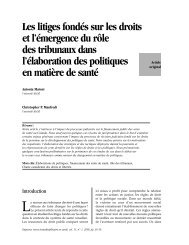
Curvature<br />
radius<br />
Sample<br />
rigidity is calculated as the slope <strong>of</strong> the curve <strong>of</strong> the bending moment expressed as a function <strong>of</strong> the curvature<br />
as illustrated in Fig. 2b. Since this measurement involves uniaxial deformations and since textiles, which are<br />
included in most <strong>of</strong> the <strong>gloves</strong>, are generally anisotropic materials, i.e. with physical properties different in each<br />
direction, <strong>gloves</strong> were tested along both main directions.<br />
The bending rigidity was measured on samples taken in the glove palm along the longitudinal and transversal<br />
directions. For each glove model, three replicas were measured, allowing for the calculation <strong>of</strong> a mean<br />
and a standard deviation.<br />
2.2. The free-deforming multidirectional test method<br />
Bending<br />
moment<br />
(μN.m/m)<br />
Fig. 2. Bending rigidity with the KESF method.<br />
Curvature<br />
(m -1 )<br />
The principle <strong>of</strong> the free-deforming multidirectional test method is based on the use <strong>of</strong> a probe to push a<br />
sample through an orifice drilled in a platform (see Fig. 3). The lap edge <strong>of</strong> the orifice is chamfered to limit<br />
stress concentration. Because <strong>of</strong> the larger thickness <strong>of</strong> <strong>gloves</strong> compared to fabrics, the value <strong>of</strong> the gap<br />
between the probe head and orifice diameters has been almost doubled, the probe and orifice diameters being<br />
respectively equal to 35.8 mm and 57.0 mm. In order to limit the stress concentration at the probe head and to<br />
better simulate the type <strong>of</strong> deformations applied to <strong>gloves</strong> while in use, the probe head includes a conical section<br />
with an angle <strong>of</strong> 30° and an 11.56-mm-radius spherical tip. This geometry produces double curvature<br />
deformations (Laroche and Vu-Khanh, 1993). To account for the influence <strong>of</strong> the glove fingers, the diameter<br />
<strong>of</strong> the probe is maintained at a constant value up to the top, as illustrated in Fig. 4, which displays the experimental<br />
set-up inserted into an 1137 Instron tensile testing frame with a glove positioned palm up above the<br />
orifice.<br />
The force–displacement curve is recorded while the glove, positioned palm up laying on the platform with<br />
its palm centered above the orifice, is pushed through it by the probe traveling at a rate <strong>of</strong> 100 mm/min.<br />
Fig. 3. Schematic representation <strong>of</strong> the free-deforming multidirectional method set-up.