HP Series Operating Manual - Jands
HP Series Operating Manual - Jands
HP Series Operating Manual - Jands
- No tags were found...
Create successful ePaper yourself
Turn your PDF publications into a flip-book with our unique Google optimized e-Paper software.
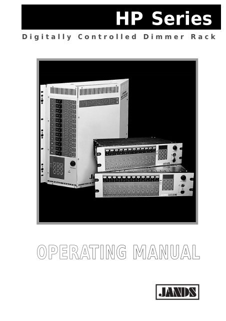
<strong>HP</strong> <strong>Series</strong>Digitally Controlled Dimmer RackOPERATING MANUAL
ContentsiEMC COMPLIANCEThis product is approved for use in Europe and Australia/New Zealand and conforms to the following standards:European NormsAustralian / New ZealandStandardsEN 50081-1 AS/NZS 4252.1EN 50082-1 AS/NZS 4251.1EN 60950 AS/NZS 3260To ensure continued compliance with EMC Directive 89/336 and the Australian Radiocommunications Act 1992, useonly high quality data cables with continuous shield, and connectors with conductive backshells. Examples of suchcables are:DMX: Belden 8102 100% Aluminium foil screen, 65% Copper braid.© JANDS ELECTRONICS PTY LTD 1997All rights reservedDISCLAIMERInformation contained in this manual is subject to change without notice and doesnot represent a commitment on the part of the vendor. JANDS ELECTRONICS P/Lshall not be liable for any loss or damage whatsoever arising from the use ofinformation or any error contained in this manual.It is recommended that all service and repairs on this product be carried out byJANDS ELECTRONICS P/L or its authorised service agents.JANDS <strong>HP</strong> <strong>Series</strong> dimmers must only be used for the purpose they were intended bythe manufacturer and in conjunction with this operating manual.JANDS ELECTRONICS P/L cannot accept any liability whatsoever for any loss ordamage caused by service, maintenance or repair by unauthorised personnel, or byuse other than that intended by the manufacturer.Manufactured in Australia by:JANDS ELECTRONICS PTY LTD ACN 001 187 83740 KENT RDLocked Bag 15MASCOT NSW 2020AUSTRALIAPHONE: +61-2-9582-0909FAX: +61-2-9582-0999EMAIL: jandsinfo@jands.com.auRevision 2 - 20 March, 1997 <strong>HP</strong> SERIES DIMMER OPERATING MANUAL
ContentsiiTable of ContentsTable of Contents1.0 Introduction2.0 Equipment Description2.1 Front panel layout...................................................................................................2-03.0 Getting Started3.1 Connecting power...................................................................................................3-03.2 Connecting loads ....................................................................................................3-13.3 Connecting DMX-512 input ...................................................................................3-13.4 Power-up sequence.................................................................................................3-24.0 Dimmer Operation4.1 Menu structure .......................................................................................................4-04.1.1 ENTER ....................................................................................................4-04.1.2 NORMAL................................................................................................4-04.1.3 CLEAR....................................................................................................4-04.1.4 MODE menu............................................................................................4-04.1.5 DMX CHannel menu ...............................................................................4-54.1.6 DMX BANK menu ..................................................................................4-64.1.7 BUILD menu ...........................................................................................4-64.1.8 RUN menu...............................................................................................4-74.1.9 TEST function..........................................................................................4-94.2 Deep clear ..............................................................................................................4-94.3 Channel disable ....................................................................................................4-104.4 Software update....................................................................................................4-10Revision 2 - 20 March, 1997 <strong>HP</strong> SERIES DIMMER OPERATING MANUAL
Contentsiii5.0 Fault Diagnosis5.1 Protection ...............................................................................................................5-05.1.1 Output protection .....................................................................................5-05.1.2 Thermal protection...................................................................................5-15.1.3 Supply Power fault protection ..................................................................5-15.2 Output faults...........................................................................................................5-25.3 <strong>Operating</strong> faults ......................................................................................................5-25.4 DMX faults.............................................................................................................5-35.5 Phase fault indication..............................................................................................5-35.6 Cold lamp filaments................................................................................................5-35.7 Output Loads..........................................................................................................5-35.8 Fault finding guide..................................................................................................5-46.0 Installation6.1 Rack mounting .......................................................................................................6-06.1.2 Mounting in racks 465mm deep ...............................................................6-06.1.2 Mounting in deep racks using the Extender brackets.................................6-16.1.3 Rack Mounting - Ventilation ....................................................................6-26.2 Wall Mounting .......................................................................................................6-26.2.1 Wall Mounting Dimmers - In Racks.........................................................6-36.2.2 Wall Mounting Dimmers - Flush to Wall..................................................6-46.2.3 Wall Mounting Dimmers - Straddling Cable Trays...................................6-56.2.4 Wall Mounting Dimmers - Conduited Cable Entry...................................6-66.2.5 Wall Mounting Dimmers - Hung from Bar Hooks....................................6-76.2.6 Wall Mounting Dimmers - Patch Lead Option..........................................6-86.3 Mounting the dimmer to the bracket .......................................................................6-96.4 Wall Mounting Dimmers - Ventilation..................................................................6-107.0 MaintenanceRevision 2 - 20 March, 1997 <strong>HP</strong> SERIES DIMMER OPERATING MANUAL
Contentsiv8.0 Technical Data and Specifications8.1 Multipin output connector pin-outs.........................................................................8-28.2 DMX connector pin-outs ........................................................................................8-58.3 DMX bank allocations............................................................................................8-58.4 Mains wiring colour codes......................................................................................8-68.5 Internal Mains Wiring.............................................................................................8-68.5.1 Normal Three Phase plus Neutral Operation.............................................8-68.5.2 Single Phase Operation ............................................................................8-68.5.3 Delta Supply Operation ............................................................................8-78.5.4 Operation in Europe .................................................................................8-7Revision 2 - 20 March, 1997 <strong>HP</strong> SERIES DIMMER OPERATING MANUAL
BLANKPAGE
Introduction 1-01.0 IntroductionThe JANDS <strong>HP</strong>12 series dimmers are rugged, high quality, 12 channel, 2.5kVA perchannel dimmers specifically designed for demanding touring and theatreapplications.The <strong>HP</strong>12-TR features opto-controlled Triacs and medium risetime chokes; the <strong>HP</strong>12-SC features DC-fired SCR pairs and high risetime chokes.Complementing the <strong>HP</strong>12-TR / <strong>HP</strong>12-SC are the <strong>HP</strong>12-WMTR (wall-mounted Triacdimmer) and the <strong>HP</strong>12-WMSC (wall-mounted SCR dimmer).The <strong>HP</strong>12 series of dimmers feature microprocessor-based digital control. A keypad,rotary encoder, channel switches, LED indicators and a large alphanumeric displayenable the user to monitor and select the built-in functions.The user has the ability to select the DMX start number either by channel number orin banks of 12 channels, test selected channels while the remainder of the dimmerstays “on line”, select output voltage (eg. 120V) or ramp curves for designatedchannels, capture up to three non-volatile DMX “snapshots”, build two user-definablenon-volatile scenes with the ability to import/select/set individual channel levels, andto select from six “factory” built-in scenes including chases/random/crossfades. Otherfunctions also provided include dimmer “soft” start, channel-by-channel preheatfunction, the ability to monitor the status of the dimmer rack in relation to supplyvoltage, a bad (soft) neutral connection, over-temperature and other workingparameters of the unit.The dimmer will “wake-up” in the mode it was last programmed to run - an idealfunction for stand alone applications. If no particular mode has been previouslydefined, the dimmer rack looks for DMX control. If the rack loses DMX control atany time while running, it defaults to the last received DMX command.<strong>HP</strong> dimmers feature JANDS’ Ferrodip chokes. These chokes provide high rise timealong with excellent high frequency noise suppression and low acoustic noise.The <strong>HP</strong> range of dimmers has been designed to allow for future optional upgrades tothe operating system.Control signal to rack-mount dimmers is via a standard DMX-512 socket at either thefront panel or rear panel, while the dimmed outlets and three phase power entry arelocated on the rear panel.Control signal and three phase power entry to wall-mount dimmers are on internalscrew terminal blocks, while the dimmed outlets are on either internal screw terminalblocks or front outlets (GPO's).Bracket systems for the wall-mounted dimmers allow a wide variety of mountingoptions - flush to the wall with rear wire entry, straddling cable trays, conduitedwiring from all four sides or mounted in standard rack frames and strips.Revision 2 - 20 March, 1997 <strong>HP</strong> SERIES DIMMER OPERATING MANUAL
Introduction 1-1Some key features of the dimmer range include:FEATURE <strong>HP</strong>12-TR <strong>HP</strong>12-SC <strong>HP</strong>12-WMTR<strong>HP</strong>12-WMSC3RU rack chassis (mounting front and rear) • •Wall-mounted chassis • •Circuit breaker protection of output devices • • • •Factory-wired and tested three phase tail andconnector (export versions may vary)• •Front panel indication of three phase supply • • • •Selectable missing or failed neutral detection andshut-down• • • •Temperature-controlled cooling fan • • • •Temperature monitor and thermal cut-out • • • •DMX address selection by Channel or 12 channelBankOutput voltage selection on a channel-by-channelbasisDimming curve selectable between “linear power”and “switched output” on a channel-by-channel basis• • • •• • • •• • • •Channel level test from zero to full • • • •LED mimic of channel status, control and output • • • •Selectable lamp preheat function for extended lamplife and to avoid circuit breaker nuisance trippingPreset “Snap”, “Scene” and “Chase” settings tofacilitate setup and stand-alone dimmingapplicationsConforms to C-Tick (Australian) and CE (European)standardsRegulation of dimmer output voltage againstvariations in mains supply voltagesInternal wiring options allow supply from threephase star supply or three independent supplies<strong>Operating</strong> software updatable without removing thelid.• • • •• • • •• • • •• • • •• • • •• • • •"Bulletproof" SCR pairs for extreme reliability • •Continuous DC gate firing, allowing accuratecontrol of "difficult" loads and loads down to 5 wattsHigh risetime chokes for low acoustic lamp filamentnoise and low wiring noise• •• •Single 80mm speed-controlled fan • •Dual 80mm speed-controlled fans • •Revision 2 - 20 March, 1997 <strong>HP</strong> SERIES DIMMER OPERATING MANUAL
BLANKPAGE
1 7 6 2 5 3SELECTSELECTTR1011984Figure 2.1
Equipment Description 2-02.0 Equipment Description2.1 Front panel layoutE Figure 2.1 (Rack-mount)1. Channel output circuit breakers: The circuit breakers are rated at 11.5 ampscontinuous, however <strong>Jands</strong> recommend the maximum load connected to a channel belimited to 10A. If nuisance tripping occurs, enable the Preheat option (see section4.1.4.5). See also section 5.6 for a full explanation of nuisance tripping.2. Display: A red four digit alpha-numeric display is used to show dimmer status andoption menus.3. LEVEL/FUNCTION encoder wheel: This detent action control knob is used toselect items from the menus, and to select the channel levels or chase rate (dependingon the operating mode).4. DMX IN/LOOP connectors (Rack-mount only): A standard five pin AXRconnector inputs control desk DMX-512 signals and a second “Loop” connectoroutputs them to other dimmers. See section 8.2 for wiring details.5. DMX IN LED: A green LED indicates the presence of DMX signals.6. Keypad: These switches are used to select different options and operating modes.A red LED is associated with each switch to indicate activation of selected function.7. PHASE LEDs: Three green LEDs (one for each phase) indicate that the threemains supply phases are available.8. Channel SELECT switch: These select or deselect options for each channel, orswitch a channel between “on-line” and “off-line”. If a channel is “off-line”, it will notrespond to the DMX input signals.9. Channel STATUS LED: A bi-colour LED indicates channel status, ie.Red = channel set for 60 or 120V outputGreen = channel set for 240V outputOff = channel disabledOrange = voltage change selected but not yet confirmedFlashing = channel selected for changes to be made10. DRIVE LED: This green LED indicates a control signal is being applied to thatchannel.Revision 2 - 20 March, 1997 <strong>HP</strong> SERIES DIMMER OPERATING MANUAL
Equipment Description 2-111. LOAD LED: This red LED serves two functions. In normal operation, it acts asan output mimic. When the channel drive is at zero, it indicates whether that channel’sload is disconnected (or open-circuit).To check a load, set the channel drive to zero. The LOAD LED will turn ON if thereis no load.For levels above zero, the LOAD LED will mimic the channel output whenever a loadis connected.Note that the channel circuit breaker must be ON for the LOAD LED circuitry towork.BREAKER LOAD CHANNEL DRIVE LOAD LED STATUSon not connected off ONon connected off OFFon connected on OUTPUT MIMICoff doesn’t matter doesn’t matter OFFRevision 2 - 20 March, 1997 <strong>HP</strong> SERIES DIMMER OPERATING MANUAL
Getting Started 3-03.0 Getting StartedIn this manual references to individual front panel controls and LEDs will be inuppercase bold text, eg. MODE, while references to display messages will be inquotation marks, eg. “OK”.3.1 Connecting powerThe mains supply to the <strong>HP</strong>12-WMTR and <strong>HP</strong>12-WMSC dimmers must be protectedby upstream circuit breakers or fuses rated at 50 amps or less. Refer to section 8.5.RACK MOUNTED:The power plug should be connected to an appropriately rated socket outlet. Theplug’s retaining lock ring (if present) must be screwed home.WARNINGDAMAGE TO THE PLUG MAY OCCUR IF THE RETAINING LOCK RINGIS NOT PROPERLY SECURED.WALL MOUNTED:The power cable is terminated within the dimmer at a labelled six-way terminal blockand a separate earthing block. The supply neutral conductor must be the same size asthe active conductors. The six-way terminal block has three poles for the three livemains phases (labelled A1, A2, A3), and three poles for the mains neutral (N1, N2,N3). The three neutral poles are bridged by a copper link, with the incoming mainsneutral connected to terminal A2.WARNINGCONFIRM THE COLOUR OF THE MAINS NEUTRAL CONDUCTOR ATTHE SUPPLY SOURCE.ISOLATE POWER AT THE SOURCE BEFORE PERFORMINGCONNECTION.ALL UNITS:Turn on the power and check that the three PHASE indicator LEDs and the alphanumericdisplay on the front panel are on before connecting any loads. If the PHASELEDs or the display indicate a fault condition, power down and remedy the faultbefore trying again. See section 5.5 regarding phase faults.After initialisation, the display will scroll a message “DMX START CHANNELxxx”, where xxx is the last programmed DMX Start Channel (between 1 and 512).After this the display will show whatever it was showing before turning off the power.If all is well, power down and proceed to the next section.Revision 2 - 20 March, 1997 <strong>HP</strong> SERIES DIMMER OPERATING MANUAL
Getting Started 3-13.2 Connecting loadsSee section 8.1 for details of load pin connections. Export models may differ fromthese configurations. Connections should be made with the supply switched off.RACK MOUNTED:The <strong>HP</strong>12-TR / <strong>HP</strong>12-SC output options are:• Twelve Clipsal 415P 10 amp three pin sockets• Two 19 pin Socapex sockets• Four 19 pin Socapex sockets (series-wired)• Three 10 pin Wieland sockets• Rear DIN-rail mounted terminal blocksWALL MOUNTED:The <strong>HP</strong>12-WMTR / <strong>HP</strong>12-WMSC output options are:• Twelve Clipsal 415P 10 amp three pin sockets• Wieland 3-pin sockets• Internal DIN-rail mounted terminal blocksExport models may differ from these configurations.3.3 Connecting DMX-512 inputThe dimmer input signal should conform to the USITT DMX-512 (1990)specification. The green DMX IN LED indicates the presence of DMX signals. Seesection 8.2 for connector wiring details.RACK MOUNTED:The DMX input to the <strong>HP</strong>12-TR / <strong>HP</strong>12-SC dimmers connects to the DMX IN socketon the front panel. The DMX signal may be daisy-chained to the next dimmer via theLOOP socket.WALL MOUNTED:The DMX input to the <strong>HP</strong>12-WMTR / <strong>HP</strong>12-WMSC dimmers connects to a circuitcard using a labelled screw terminal block. The DMX “thru” signal may be daisychainedto the next dimmer via the LOOP terminal block.Revision 2 - 20 March, 1997 <strong>HP</strong> SERIES DIMMER OPERATING MANUAL
Getting Started 3-23.4 Power-up sequenceWhen powering up, the following sequence should be used:1 Power up the control desk.2 Power up any softpatches and/or DMX receivers.3 Power up the dimmers last, preferably one at a time starting from the firstdimmer rack in the DMX loop.This procedure minimises the risk of lamps and fixtures responding to any false DMXdata produced by control desks or ancillary equipment at turn-on (producing thelighting equivalent of an audio “thump”) and prevents damage to lamps, dimmers, andother controlled devices.Use the reverse procedure when powering down.Revision 2 - 20 March, 1997 <strong>HP</strong> SERIES DIMMER OPERATING MANUAL
MODE 1: VOLTAGE, TEMPERATURE, LAW, PREHEAT, VOLTAGE FLUCTUATION(Termination, Check, Voltage Compensation & Lock to be continued next page)60V selection applied120V selection applied240V selection appliedLinear-Power selection appliedSwitched output selection appliedPreheat "On" selection appliedPreheat "Off" selection appliedPreheat level setNeutral detect "On" selection appliedNeutral detect "Off" selection appliedENTERENTERENTERENTERENTERENTERENTER[9]ENTERENTERENTERSTATUSSTATUSSTATUSSTATUSSTATUSSTATUSSTATUSSTATUSSELECTSELECTSELECTSELECTSELECTSELECTSELECTSELECT[Hold whilesetting level][1][2][3][4] [5][6] [7][8][1] DISPLAY = "Select channels for60V"ENTERENTERENTER NORMALENTER ENTER ENTERENTERENTERENTERENTER[2]DISPLAY = "Select channels for120V"Voltage choice for selected channel[Voltage choice for selected channelVoltage choice for selected channelCurrent core temperatureLinear-PowerSwitched OutputPreheat "On"Preheat "Off"Preheat "Level"Neutral detect "On"Neutral detect "Off"[3] DISPLAY = "Select channels for240V"[4]DISPLAY = "Select chans forLinear-Power"[5]DISPLAY = "Select chans forSwitched Output"ENTERENTERENTERENTERENTER[6]DISPLAY = "Select chans forPreheat on"VoltageTemperatureLawPreheatPower Fault[7] DISPLAY = "Select chans forPreheat off"To "TERM" [8] DISPLAY = "Press select and holdwhile changing channel preheat"MODE[START]MODE[9] DISPLAY = "A"(a letter between A and E)Status LED red = 60V or 120VStatus LED green = 240VStatus LED orange = Channelselected for output voltage changeFigure 4.1 A
Dimmer Operation 4-04.0 Dimmer OperationThis section assumes the dimmer has been correctly connected to three phase powerand a source of DMX input signals as described in section 3.0.4.1 Menu structureThe <strong>HP</strong>12-TR dimmers feature a “tree” menu structure. This means that an option ischosen from the display with the LEVEL/FUNCTION encoder wheel, and theENTER keypad button is then pressed to confirm the selection.The encoder wheel is then used to select the next level of options, the ENTER buttonis pressed to confirm the selection, and so on.After all the options have been selected, the display reverts to “OK” to indicate thedimmer is now back in normal operating mode.The display will flash if there are more menu levels above the current one.4.1.1 ENTERThe ENTER keypad button is always pressed to confirm a menu or channel selection.4.1.2 NORMALThe NORMAL keypad button cancels the current menu selection and allows theoperator to start again in the event of an error. The display shows “OK”.Pressing NORMAL while “OK” is displayed shows the dimmer software version.4.1.3 CLEARThe CLEAR keypad button is used to go back one menu level if an option isincorrectly selected.4.1.4 MODE menuE Figure 4.1ASelect the MODE button on the keypad. The display will then “flash” showing oneof the MODE options, which are:• “VOLT” - output voltage selection• “TEMP” - heatsink temperature monitor• “LAW” - dimmer law• “PREH” - filament preheat• “P.FLT” - mains input voltage fault (power fault) test enable• “TERM” - DMX input termination• “CHEK” - display dimmer operating parameters• “V.COM”- enable/calibrate voltage compensation• “LOCK” - lock dimmer functionsRevision 2 - 20 March, 1997 <strong>HP</strong> SERIES DIMMER OPERATING MANUAL
Dimmer Operation 4-1To select an option, rotate the FUNCTION encoder wheel until the desired option isdisplayed, then press the ENTER keypad button to confirm the selection.4.1.4.1 “VOLT” - Voltage selectionE Figure 4.1AAny or all of the dimmer channels may be customised to give either 240, 120, or60 volt output. This feature is useful for controlling individual 120 volt loads,such as single PAR 64 (120) lamps, Leko (FEL) or other 120 volt lamps (120V),or series pairs of ACLs (60V).• Once the VOLT option has been selected, use the FUNCTION encoderwheel to select either “240V”, “120V”, or “60” and press ENTER.• If “240V” is selected, the display will stop flashing and will scroll thefollowing message: “SELECT CHANNELS FOR 240V”.• If “120V” is selected, the display will stop flashing and will scroll thefollowing message: “SELECT CHANNELS FOR 120V”.• If “60V” is selected, the display will stop flashing and will scroll thefollowing message: “SELECT CHANNELS FOR 60V”.• Press the SELECT button on the channel to be changed. The STATUS LEDof the channel(s) selected will change colour to orange.• Once all the required channels are selected, press ENTER to make thechanges. The channel STATUS LED(s) will show green for those channel(s)set to 240 volt output, and red for those channel(s) set to 60 or 120 voltoutput.• The display will then show “OK” to indicate the dimmer is now in normaloperating mode with the selected changes implemented.CAUTIONSELECTING A 60 or 120 VOLT LAMP TO 240 VOLTOPERATION CAN CAUSE SERIOUS DAMAGE TO THE LAMP !4.1.4.2 “TEMP” - Temperature monitorE Figure 4.1AThe internal heatsink temperature may be monitored by selecting “TEMP”. Thedisplay shows the temperature in degrees Celsius, eg “24ºC”. Normal DMXoperation of the dimmer is unaffected by selecting this function. Pressing theNORMAL button on the keypad will clear the display to “OK”.NoteThe <strong>HP</strong>12-TR / <strong>HP</strong>12-SC dimmers are designed to be installed in standard19-inch wide racks. These racks should have adequate ventilation allowingfor the side-to-side airflow of the dimmers. Fully enclosed racks that obstructside-to-side ventilation may cause overheating problems.Revision 2 - 20 March, 1997 <strong>HP</strong> SERIES DIMMER OPERATING MANUAL
Dimmer Operation 4-24.1.4.3 “LAW” - Dimmer lawE Figure 4.1ASelecting “LAW” gives the option of either a linear power curve - “Lin P” - or aswitch curve - “Swch”. The linear power curve gives even fade characteristics forlamps, while the switch curve may be used for switching other devices (eg. fans,strobes, motors, etc) on or off, with the switching points set at 55% for upfadesand 45% for downfades.• Use the FUNCTION encoder wheel to change the law, and press ENTER toselect.• Next press the channel SELECT buttons to select the channels to be changed.The channel STATUS LEDs will flash. Press ENTER to make the changes.• The display will change to “OK” to indicate the dimmer is now in normaloperating mode with the selected changes implemented.4.1.4.4 “PREH” - Filament preheatE Figure 4.1AIf a channel is fully loaded, there is a possibility that cold filament inrush currentmay cause nuisance tripping of the circuit breakers. If this is a problem, thepreheat - “PREH” - option may be used to reduce the inrush. When preheated,the filaments may show a barely perceptible dull orange glow.Preheat has no effect when the lamp is being driven above the preheat level or forchannels set to switched output. See section 5.6 for an explanation of coldfilament inrush current.• Selecting “PREH” gives the options of “ON”, “OFF”, and “LEVL”. Usethe FUNCTION encoder wheel to choose the option and press ENTER toconfirm selection. Selecting “LEVL” allows the control of the preheat levelfor each channel regardless of whether preheat is turned on or off for thatchannel.When “ON” or “OFF” has been selected:• Press the channel SELECT button(s) to select preheat for the desiredchannel(s).• The channel STATUS LED(s) will “flash” when that channel is selected.Press ENTER to make the change(s).• The display will change to “OK” to indicate the dimmer is now in normaloperating mode with the selected change implemented.When “LEVEL” has been selected:• Press and hold the channel SELECT button for the desired channel. Whileholding SELECT button adjust the encoder wheel to set the desired preheatlevel. Preheat is adjustable in 5 levels from A (lowest) to E (highest).• Press ENTER to make the change(s) permanent.• The display will change to “OK” to indicate the dimmer is now in normaloperating mode with the selected change implemented.Normal DMX operation of the dimmer is unaffected by selecting this function.Revision 2 - 20 March, 1997 <strong>HP</strong> SERIES DIMMER OPERATING MANUAL
MODE 2: TERMINATION, CHECK, VOLTAGE COMPENSATION & LOCKDimmer unlockedTurn right for1 stepTurn right for1 stepENTERDMX terminatedDMX not terminatedVoltage compensation appliedVoltage compensation not appliedENTERENTERTurn left for1 stepENTERNORMALAdjust to scrollthrough channelDimmer lockedENTERENTER[10]ENTERENTERENTERENTERENTERTerm "On"Term "Off"ENTERENTERENTERENTERDMX TerminationDimmer Parameter ReadoutMains Voltage CompensationDimmer user lockFrom "P.FLT"[10]DISPLAY = "CH1*DMX-1*Level-19*Volt-240*Law-Linear power*Preheat-Off*Preheat value-E*Status-Enabled"Figure 4.1 B
Dimmer Operation 4-34.1.4.5 “P. FLT” - Mains Power FaultE Figure 4.1AThe <strong>HP</strong>12-TR / <strong>HP</strong>12-SC dimmers will detect three types of mains supplyproblems:• Mains overvoltages• Mains undervoltages• Neutral-to-earth overvoltageIn some venues the three phase power supply may be less than ideal, and one ormore of the above fault conditions may occur without the wiring being truly“faulty”. For this reason it is possible (BUT NOT RECOMMENDED) to use theP.FLT option to turn off the power fault detect ("the show must go on").ALWAYS check first that the problem is not a dropped neutral in either of thethree phase connectors, or a missing earth connection.WARNINGIF THE NEUTRAL DETECT FACILITY IS DISABLED, IT IS POSSIBLETHAT UNSAFE MAINS SUPPLY WIRING MAY NOT BE DETECTED.The <strong>HP</strong>12-TR / <strong>HP</strong>12-SC dimmers will tolerate and even correct for mainssupply problems of sufficient magnitude to damage less tolerant equipmentconnected to the same supply. The <strong>HP</strong>12-TR / <strong>HP</strong>12-SC detection facilities maybe used to provide "early warning" protection for ancillary equipment. Section5.1.3 gives a more in-depth explanation of this facility.• Selecting “P.FLT” gives the options of “ON” or “OFF”. Use theFUNCTION encoder wheel to choose the option and press ENTER toconfirm selection.• The display will change to “OK” to indicate the dimmer is now in normaloperating mode with the selected change implemented.Normal DMX operation of the dimmer is unaffected by selecting this function.4.1.4.6 “TERM” DMX Signal TerminateE Figure 4.1BSelecting “TERM” allows the DMX signal to be correctly terminated, as isrequired for the last dimmer in a DMX line. Note that when set to “ON” theDMX Loop connector in unused.Pressing the NORMAL button on the keypad will change the display to “OK” toindicate the dimmer is now in normal operating mode.4.1.4.7 “CHEK” dimmer operating parameter displayE Figure 4.1BSelecting “CHEK” displays the dimmer’s operating parameters on a channel bychannel basis. This is useful for checking that a dimmer has been setup correctly.Select the channel to be checked by turning the FUNCTION encoder wheel (theSTATUS LED of the channel being checked will flash). Stop the scrolling of theRevision 2 - 20 March, 1997 <strong>HP</strong> SERIES DIMMER OPERATING MANUAL
Dimmer Operation 4-4display at any time by pressing ENTER. Press ENTER and turn the encoderwheel at the same time to display information “vertically”, ie. display the sameinformation for different channels.Pressing the NORMAL button on the keypad will change the display to “OK” toindicate the dimmer is now in normal operating mode.Normal DMX operation of the dimmer is unaffected by selecting this function.4.1.4.8 “V.COM” Output voltage CompensationE Figure 4.1BAn <strong>HP</strong> dimmer can be setup so that it will compensate for variations in the mainsinput voltage. Selecting “V.COM” allows the internal voltage compensation tobe turned on or off, or calibrated.• Selecting “V.COM” gives the options of “ON”, “OFF”, “LINE” and“MAX”. Use the FUNCTION encoder wheel to choose the desired optionand press ENTER to confirm selection. Selecting “LINE” allows calibrationfor the voltage compensation, while selecting “MAX” allows setting of themaximum output voltage the dimmer regulates to.When “ON” or “OFF” has been selected:The display will change to “OK” to indicate the dimmer is now in normal operatingmode with the selected change implemented.When “LINE” has been selected:• Note that an external voltmeter is necessary to complete this procedure.This parameter should not need to be adjusted during normal operation.Adjust the displayed voltage using the FUNCTION encoder wheel until itreads the same as the current input voltage, as displayed on the voltmeter. It isrecommended that all phases be driven from a single phase source eg. via asingle to three phase adaptor, to eliminate phase voltage variations.• Press ENTER to calibrate the dimmer.• The display will change to “OK” to indicate the dimmer is now in normaloperating mode with the selected change implemented.When “MAX” has been selected:• Adjust the displayed voltage using the FUNCTION encoder wheel until it isequal to the desired maximum output voltage from the dimmer when driven tofull. eg to avoid running 220 volt lamps above their rated voltage set thisparameter to 220V.• Press ENTER to set the maximum output voltage from the dimmer.• The display will change to “OK” to indicate the dimmer is now in normaloperating mode with the selected change implementedNote that the voltage compensation system works within the followinglimitations:1 The output cannot be driven above the input voltage. eg if the MAX value isset to 240, and the mains input voltage is 220, the maximum voltage availableat the output is 220 volts.2 The compensation system does not operate on switched outputs (ie. channelsRevision 2 - 20 March, 1997 <strong>HP</strong> SERIES DIMMER OPERATING MANUAL
BLANKPAGE
TEST, DMX BANK, DMX CHANNEL, DEEP CLEAR[Exit to DMX operation][DMX BANK selected ][DMX start number selected ][Exit to DMX operation ]ENTERNORMALENTERENTER[Number of channels for dimmer][Number of channels for dimmer]FUNCTIONLEVEL[1][2][Selected DMX BANK value][Selected DMX start channel]ENTERSTATUSSELECT[Selected output voltage][Selected output voltage][DMX BANK value]FUNCTION[DMX BANK No. ][DMX start channel]FUNCTION[DMX start level ]POWERFUNCTION[1][2]Repeat for each channel to be tested.All remaining channels will operateas normal.Will display bank number in blocksof 12 channels (6 channels for <strong>HP</strong>6)[3]For DEEP CLEAR. Turn off power.Hold MODE and DMX BANK simultaneouslywhile turning on power.TEST[START]TESTDMX BANK[START]DMX BANKDMX CH.DMX CHANNEL[START]MODE DMX BANKDEEP CLEAR [3][START]After a deep clear, it is necessary toreprogram the dimmer to indicateoutput voltage 110V or 240V andnumber of channels (12 for <strong>HP</strong>12).Status LED red = 110VStatus LED green = 240VFigure 4.2<strong>HP</strong> DIMMER MS-9507-02
Dimmer Operation 4-5with dimmer law set to “switch”).3 The dimmer must be correctly calibrated as outlined above.Normal DMX operation of the dimmer is unaffected by this procedure, howeverthe dimmed output level may change due to normal operation of thecompensation system.4.1.4.9 “LOCK” Parameter Lockout FacilityE Figure 4.1BIf the dimmer is to be left unattended it is sometimes desirable to be able to lockthe settings such that unauthorised users cannot alter them. The “LOCK” optionprovides this facility.• Selecting “LOCK” gives the single option of “ON”. Pressing ENTER locksthe dimmer, and “LOCK” is displayed.• To unlock a dimmer, turn the FUNCTION encoder wheel one step to the left,press enter, one step to the right, press enter, and finally one step to the right.If a mistake is made during the unlock procedure, turn the wheel more thanthree steps to the right to reset the sequence and try again.• When the dimmer has been unlocked it will display “OK”.Normal DMX operation of the dimmer is unaffected by selecting this function.4.1.5 DMX CHannel menuE Figure 4.2The dimmer’s DMX start channel can be selected anywhere from channel 1 tochannel 512. By selecting DMX start channel 1, the dimmer will respond to DMXchannels 1 through 12 inclusive. When using racks of looped dimmers, the nextdimmer should start at channel 13, the next at channel 25, and so on.• To select a DMX start channel press the DMX CH button on the keypad.• The display will change to show the currently assigned DMX start channel.• Using the FUNCTION encoder wheel, the DMX start channel may beincremented or decremented to the desired DMX channel start number.• To select the DMX start channel press the ENTER button on the keypad.• The display will then show “OK” to indicate the dimmer is now in normaloperating mode.Revision 2 - 20 March, 1997 <strong>HP</strong> SERIES DIMMER OPERATING MANUAL
BUILD: SNAP 1~3, SCENE 1 & 2[DMX snapshot recorded][Local scene recorded]ENTER[3][Channel level]STATUSENTERSELECT[1][2]ENTERENTER[1]DISPLAY = "Press Enter to store DMXvalue"[SP1: SNAP1 / SP2: SNAP2 / SP3: SNAP3][SC1: SCENE1 / SC2: SCENE 2][2]DISPLAY = "Press Select and holdwhile change level for each channel"[3] Repeat step for each channel to beincluded in selected SceneBUILDStatus LED red = 110VStatus LED green = 240VBUILD[START]<strong>HP</strong> DIMMER MS-9507-03Figure 4.3
Dimmer Operation 4-64.1.6 DMX BANK menuE Figure 4.2To make DMX start channel selection easier, the <strong>HP</strong>12-TR / <strong>HP</strong>12-SC dimmers canselect a bank of twelve channels from the DMX input signal. There are a total of 42sequential banks of twelve channels and one last bank of eight channels in the 512channels available from the DMX-512 source. See section 8.2 for a list of banks andtheir corresponding channels.By selecting DMX start bank 2, the dimmer will respond to DMX channels 13through 24 inclusive.4.1.7 BUILD menu• To select a DMX bank press the DMX BANK button on the keypad.• The display will change to show the currently assigned DMX bank number.• Using the FUNCTION encoder wheel, DMX bank numbers may beincremented or decremented to the desired bank number.• To select the DMX bank number press the ENTER button on the keypad.• The display will then show “OK” to indicate the dimmer is now in normaloperating mode.E Figure 4.3The BUILD menu is used to record DMX Snapshots or user-defined Scenes.• Press the BUILD keypad button.• Select a flashing Snapshot number (“SP1 - SP3”) or a Scene number (“SC1 -SC2”) to record, using the FUNCTION encoder wheel.• Press ENTER to confirm the selection.4.1.7.1 SnapshotE Figure 4.3Once a SNAPSHOT number is selected (“SP1”, “SP2” or “SP3”), the displaywill scroll the message: “PRESS ENTER TO STORE DMX VALUE”.• On pressing ENTER, the dimmer will store the current DMX values for thetwelve dimmer channels in the currently selected bank.• The display will change to “OK” to indicate the dimmer is now in normaloperating mode.Revision 2 - 20 March, 1997 <strong>HP</strong> SERIES DIMMER OPERATING MANUAL
RUN: SNAP 1~3, SCENE 1&2, PRE-RECORDED CHASES 1~6[Exit to DMX operation] [Exit to DMX operation] [Exit to DMX operation]NORMALNORMALNORMALSTATUS[over all Level of SNAP]STATUS[over all Level of SCENE]STATUS[Speed in B.P.M.]SELECTSELECTSELECT[Stand alone channel level][4] [4] [4][Stand alone channel level][Stand alone channel level]STATUSSTATUSSTATUS[Speed]SELECTSELECTSELECT[SP1: SNAP1 / SP2: SNAP2 / SP3: SNAP 3]ENTER[1] [2] [3]ENTERENTER[SC1: SCENE1 / SC2: SCENE2][PR1 -PR6: Prerecorded chases][1] DISPLAY = "SP1 on level 100""SP2 on level 100""SP3 on level 100"[2] DISPLAY = "SC1 on level 100""SC2 on level 100"[3] DISPLAY = "PR1 run 100 B.P.M.""PR2 run 100 B.P.M.""PR3 run 100 B.P.M.""PR4 run 100 B.P.M.""PR5 run 100 B.P.M.""PR6 run 100 B.P.M."RUN[START]RUN[4] Press SELECT and hold whileadjusting channel level via levelcontrol.This step removes the selectedchannel from a SNAP, SCENE orPRE-RECORDED CHASE andenables the channel level to beadjusted in isolation. These newlevels are not stored.Figure 4.4Status LED red = 110VStatus LED green = 240V<strong>HP</strong> DIMMER MS-9507-04
Dimmer Operation 4-74.1.7.2 SceneE Figure 4.3Once a Scene (“SC1” or “SC2”) is selected, the display will scroll the message:“PRESS SELECT AND HOLD WHILE CHANGE LEVEL FOR EACHCHAN”.• For each channel required to Build the Scene, press and hold the SELECTbutton.• The display will initially show the last recorded level for that channel, whichmay then be changed by rotating the LEVEL/FUNCTION encoder wheel.• Once all the required channels have been changed, press ENTER to confirmthe changes.• The display will change to “OK” to indicate the dimmer is now in normaloperating mode.4.1.8 RUN menuE Figure 4.4The <strong>HP</strong>12-TR / <strong>HP</strong>12-SC dimmers offer a range of pre-recorded Snapshots, Scenesand Chases that may be used for testing purposes or for when the dimmer rack isused in stand-alone (no control desk) applications.The Snapshots and Scenes must be recorded via the Build menu (see section 4.1.7).The Chase patterns are factory-set and cannot be changed. The output levels ofSnapshots and Scenes may be varied with the LEVEL/FUNCTION encoder wheel,which becomes a master level control. During chases the encoder wheel becomes achase rate control.In all cases, individual channel levels may be changed. Once changed, however, theyremain at the new level regardless of the setting of the master level control.Note that any previously disabled channels will remain disabled when in RUNmode, with chase sequences abbreviated to avoid visible gaps.• To run a Snapshot, Scene or Chase, press the RUN keypad button.• Select either a Snapshot (“SP1”, “SP2”, or “SP3”), a Scene (“SC1” or“SC2”), or a Factory Preset Chase (“PR1”, “PR2”, “PR3”, “PR4”, “PR5”,or “PR6”) with the FUNCTION encoder wheel.• Press ENTER to confirm the selection.4.1.8.1 SnapshotE Figure 4.4If Snapshot 2 (“SP2”) is selected, the display will scroll with the message “SP2ON LEVEL 100”.• The output level may be altered with the LEVEL/FUNCTION encoderwheel and the display will indicate a level between 100% and 0%.• Pressing a channel SELECT button will isolate that channel from the masterlevel control. The STATUS LED will flash to show the channel is isolated.Pressing the SELECT button again will re-connect the channel to the masterlevel control.Revision 2 - 20 March, 1997 <strong>HP</strong> SERIES DIMMER OPERATING MANUAL
Dimmer Operation 4-8• By pressing and HOLDING a channel SELECT button, and rotating theencoder wheel, that channel level may be modified.NoteThe master level control no longer has any effect on the level of a modifiedchannel; ie. once a channel has been modified, it remains at that level whilestill in RUN mode (regardless of the master level). The channel SELECTbutton must pressed again to re-connect that channel to the master levelcontrol.• Once the SELECT button is released, the encoder wheel becomes the masterlevel control once more.4.1.8.2 SceneE Figure 4.4If Scene 1(“SC1”) is selected, the display will scroll with the message “SC1 ONLEVEL 100”.• The overall output level may be altered with the LEVEL/FUNCTIONencoder wheel and the display will indicate a level between 100% and 0%.• Pressing a channel SELECT button will isolate that channel from the masterlevel control. The STATUS LED will flash to show the channel is isolated.Pressing the SELECT button again will re-connect the channel to the masterlevel control.• By pressing and HOLDING a channel SELECT button, and rotating theencoder wheel, that channel level may be modified.NoteThe master level control will no longer have any effect on the level of themodified channel; ie. once a channel has been modified, it remains at thatlevel while still in RUN mode (regardless of the setting of the master level).The channel SELECT button must pressed again to re-connect that channelto the master level control.• Once the SELECT button is released, the encoder wheel becomes the masterlevel control once more.4.1.8.3 Preset chasesE Figure 4.4If Preset Chase 4 (“PR4”) is selected, the display will scroll with the message“PR4 RUN 100 b.P.M.”.• The chase rate may be altered with the FUNCTION encoder wheel and thedisplay will indicate a rate between 6 and 600 beats per minute.• By pressing and HOLDING a channel SELECT button, and rotating theencoder wheel, that channel level may be edited.• Once the SELECT button is released, the encoder wheel becomes the chaseRevision 2 - 20 March, 1997 <strong>HP</strong> SERIES DIMMER OPERATING MANUAL
Dimmer Operation 4-9rate control once more. There is no master level control for this function.The factory Preset Chase patterns for <strong>HP</strong>12-TR [<strong>HP</strong>6] are as follows:PR1 Channels 1 to 12 in sequence (12 step chase)PR2 Channels 12 to 1 in sequence (12 step reverse chase)PR3 Channels 1 to 12 in sequence (12 step shadow chase) ie. chase channel offPR4 12 Channel Random chasePR5 Channels 1 & 2 crossfade to Channels 3 & 4.....(6 step 2-channel x-fade)PR6 Channels 1, 2, 3 crossfade to Channels 4, 5, 6....(4 step 3-channel x-fade)4.1.9 TEST functionE Figure 4.2Each channel may be tested individually, or as a group, by fading them from 0 to100%. Any previously disabled channel may be selected and tested.• Press the TEST keypad button and the display will show “TEST”.• Next press the desired channel SELECT buttons. This will take the selectedchannel(s) off-line from the DMX input. The remaining channel(s) will stayon-line.• The STATUS LED(s) will flash to indicate which channel(s) are under test. Asthe LEVEL/FUNCTION encoder wheel is rotated, the channel level(s) willchange from their current level.• When all tests are completed, press the NORMAL button. The display willchange to “OK” to indicate the dimmer is now back in normal operating modeand all channels are once again on-line to the DMX input control signal.4.2 Deep clearE Figure 4.2In the event of a software “lockup” or error message (see section 5.2), the <strong>HP</strong> dimmershave a facility that enables them to be Deep Cleared.CAUTIONTHIS FUNCTION WILL ERASE THE CURRENT SETTINGS IN MEMORYAND REQUIRES RE-INITIALISING OF THE OUTPUT VOLTAGE ANDNUMBER OF CHANNELS. ENSURE THAT THE VOLTAGE IS SET TO120 VOLTS IF RUNNING ANY 120 VOLT LAMPS, OR DAMAGE TO THELAMPS MAY RESULT.• Hold down the MODE and DMX BANK buttons while turning power ON to thedimmer.• Use the FUNCTION encoder wheel to select either “120V” output or “240V”output on the display and press ENTER. Individual channel output voltage may bechanged later via the MODE menu (see section 4.1.4.1).• Next use the encoder wheel to select “12ch” output (for <strong>HP</strong>12-TR / <strong>HP</strong>12-SC),Revision 2 - 20 March, 1997 <strong>HP</strong> SERIES DIMMER OPERATING MANUAL
Dimmer Operation 4-10and press ENTER.• The display will change to “OK” to indicate the dimmer is now back in normaloperating mode.4.3 Channel disableWhen the dimmer is in normal operating mode (“OK” showing on the display), anychannel may be taken off-line by pressing its SELECT button. Pressing the button asecond time will bring that channel back on-line.The STATUS LED will be on (red or green) for all active channels, and be off for alldisabled channels.Any disabled channel(s) may still be selected and tested with the TEST function (seesection 4.1.9). Once the tests are complete and the dimmer is back in normal operatingmode, the channel(s) will resume their status prior to being tested.4.4 Software updateThe operating software of the <strong>HP</strong> dimmer may be updated via the front panel DMXinput connector. To achieve this requires the following:• <strong>HP</strong>TR or <strong>HP</strong>SC dimmer• <strong>HP</strong> download kit• IBM compatible Laptop or desktop computerTo update the software, perform the following:1 Switch the dimmer power off.2 Connect the computer serial/COM port to the DMX input of the dimmer, using thedownload cable supplied in the download kit. Disconnect any DMX terminators.3 Press and hold the ENTER button on the dimmer while turning on power to thedimmer. The dimmer display will show “LOAD”.4 Release the ENTER button.5 Run the update software as supplied with the download kit.6 The dimmer will display “DATA” and the keypad LEDs will chase while theinformation is transferred. This takes around 30 seconds.When the download has completed the display will blank while the new software ispermanantly programmed into the dimmer memory. At the completion of theprogramming the dimmer restarts.The software update facility should be used with the following notes and cautions:• The dimmer must be Deep Cleared (refer section 4.2) after downloading newoperating software.• It is recommended that dimmer software not be updated during a tour/show season,unless the installed software proves unsatisfactory for normal operation.• More than one dimmer may be updated at a time using normal DMX cables to linkthe DMX Loop connector of the first dimmer to the input of the next, etc. In thiscase steps 3 and 4 must be repeated for each dimmer, before proceeding to step 5.• Refer to the instructions supplied with the download kit for further details.Revision 2 - 20 March, 1997 <strong>HP</strong> SERIES DIMMER OPERATING MANUAL
Fault Diagnosis 5-05.0 Fault DiagnosisNOTEContact your authorised JANDS Distributor for repairs or servicing.In Australia refer all repairs to an authorised JANDS service agent or return thefaulty unit in suitable packaging to:JANDS Electronics Pty LtdService Department40 Kent RdMASCOT NSW 2020Phone +61-2-9582-0909Fax +61-2-9582-09995.1 ProtectionThe <strong>HP</strong>12-TR / <strong>HP</strong>12-SC dimmers feature several types of protection. These can begenerally classified as:• Output protection• Thermal protection• Over and Under voltage protection5.1.1 Output protectionEach of the twelve output circuits is protected by a 11.5 amp fast-acting magneticcircuit breaker. These breakers are designed to pass the rated current, but willdisconnect the output circuit for any overload condition (the larger the overload, thequicker the disconnection).NOTE: 3-pin GPO outlet sockets are rated at 10 amps. Dimmer channels shouldnot be loaded beyond the socket capacity.The breakers protect the dimmer’s output devices from short-circuit loads and faultywiring looms, and save on expensive dimmer repairs. A tripped circuit breakerindicates a load fault that requires immediate attention.Note that the Triacs in the <strong>HP</strong>12-TR will survive output short circuits under mostconditions. The more rugged SCR pairs in the <strong>HP</strong>12-SC will survive output shortsunder extreme conditions (high operating temperatures, high supply fault currentavailability, short cable length from dimmer to fault).Revision 2 - 20 March, 1997 <strong>HP</strong> SERIES DIMMER OPERATING MANUAL
Fault Diagnosis 5-15.1.2 Thermal protectionThe <strong>HP</strong>12-TR / <strong>HP</strong>12-SC dimmers feature temperature-controlled fan cooling. As theinternal temperature of the dimmer increases, the fan speed also increases. The fanbegins turning at low speed at 30°C, and reaches maximum speed at temperaturesabove 50°C.The internal heatsink temperature is constantly monitored by the dimmer. If theheatsink temperature rises above 85ºC, the dimmer will automatically shut down theoutput drive and display the message: “OVER TEMPERATURE XX O C”. Thedimmer will display this message until the temperature drops below 80ºC, at whichtime it will restart. The fan will continue to cool the heatsink during the shut downperiod.The electronic shutdown at 85°C is backed up by a 90°C buried cutout, which shutsdown power to all electronics other than the cooling fan.Note that the two fans in "SC" dimmers will run slower and quieter under averageoperating conditions than the single fan in "TR" dimmers, due to the increased airflowcapacity. In addition the fans in wall-mount dimmers will run slower and quieter thanthe fans in rack-mount dimmers due to increased natural convective cooling.5.1.3 Supply Power fault protectionThe <strong>HP</strong>12-TR / <strong>HP</strong>12-SC dimmers will detect voltage problems generated by phaseload imbalance and a poor or missing neutral connection. A poor (resistive) neutralconnection can cause arcing and overheating of the connector, and also allows thephase-to-neutral voltages to vary, causing overvoltage damage to components.Bad neutral connections account for many lamp and dimmer failures. While theinternal electronics of <strong>HP</strong>12-TR dimmers can tolerate (and correct for) these faultconditions, other equipment run from the same mains supply generally cannot.The <strong>HP</strong>12-TR / <strong>HP</strong>12-SC dimmers will detect three types of mains supply problems:• Mains overvoltages• Mains undervoltages• Higher than normal neutral-earth voltagesIn addition, the <strong>HP</strong>12 dimmers can correct and regulate the dimmed outputs againstvariations in the mains supply voltages.The <strong>HP</strong>12's electronic circuits will tolerate gross overvoltages and accidentallytransposed active-neutral connection with no internal damage and no damage to outputloads.5.1.3.1 Mains OvervoltagesIf the voltage on any supply phase exceeds the maximum volts for more than twocycles the dimmer outputs are turned OFF and the following message scrolls acrossthe display: “MAINS OVERVOLTAGE. PRESS NORMAL TO REACTIVATE”.When the overvoltage condition is removed, press the NORMAL button to reactivatethe dimmer. The outputs will restart according to the previous settings.5.1.3.2 Mains UndervoltageIf voltage on any phase drops below the minimum for more than 2 cycles the dimmeroutputs for that phase are turned OFF and the following message scrolls across thedisplay: “MAINS UNDERVOLTAGE. PRESS NORMAL TO REACTIVATE”.When the undervoltage condition is removed, press the NORMAL button toRevision 2 - 20 March, 1997 <strong>HP</strong> SERIES DIMMER OPERATING MANUAL
Fault Diagnosis 5-2reactivate the low phase. The outputs will restart according to the previous settings.5.1.3.3 Neutral - Earth VoltageIf the voltage between the neutral and earth exceeds the maximum, the dimmeroutputs are turned OFF and the following message scrolls across the display:“NEUTRAL EARTH FAULT. PRESS NORMAL TO REACTIVATE”. When theneutral-earth voltage condition is removed, press the NORMAL button to reactivatethe dimmer. The outputs will restart according to the previous settings.Neutral-earth voltages are most commonly caused by poor (resistive) neutralconnections, undersized neutral wires in supply cables, and missing or disconnectedearths. Screw terminals in connectors can loosen with use and these should be checkedwhen this fault occurs.The neutral detect facility may be disabled via the MODE menu. Refer to section4.1.4.5 for details.5.2 Output faultsIf a short-circuit lamp or output cable is plugged into the dimmer, the circuit breakerwill disconnect the fault from the dimmer. In nearly all circumstances, it is quickenough to prevent damage to the output devices (Triac or SCR).In some instances however, a failure may be experienced, although these devices areusually quite reliable and robust. If a device does fail, that channel may be isolatedwith its circuit breaker.The channel LOAD LED may be used to aid in trouble shooting. This red LED servestwo functions. In normal operation, it acts as an output mimic, but when the channeldrive is at zero, it indicates whether that channel’s load is disconnected (or opencircuit).To check a load, set the channel drive to zero. The LOAD LED will turn ON if thereis no load.For levels above zero, the LOAD LED will mimic the channel output whenever a loadis connected.Note that the channel circuit breaker must be ON for the LOAD LED circuitry towork.BREAKER LOAD CHANNEL DRIVE LOAD LED STATUSon not connected off ONon connected off OFFon connected on OUTPUT MIMICoff don’t care don’t care OFF5.3 <strong>Operating</strong> faultsIf a message should appear scrolling across the display: “ADDRESS EXCEPTIONERROR XXXXXXXX XXXXXXXX” where the Xs represent different characters,write down the complete message and contact JANDS Service Department or yourlocal JANDS Distributor, giving details of the dimmer’s operating conditions thatcaused the error. In the meantime, a Deep Clear (see section 4.2) should get theRevision 2 - 20 March, 1997 <strong>HP</strong> SERIES DIMMER OPERATING MANUAL
Fault Diagnosis 5-3dimmer working again.5.4 DMX faultsThe <strong>HP</strong> Dimmers feature a Last Hold facility that remembers the last received DMXmessage. In the event of a DMX signal cable being unplugged or severed, thedimmers will to “hold” the DMX levels until a new DMX message is provided, or aSnapshot, Scene or Chase function is selected.The DMX IN LED will light when there is a DMX signal.5.5 Phase fault indicationThe three green PHASE LEDs will light when all three power input phases arepresent.WARNINGIF ONE OR MORE PHASE LEDS IS OFF, IMMEDIATELY DISCONNECTPOWER TO THE DIMMER AND CHECK THE MAINS SUPPLIES ANDWIRING BEFORE RE-CONNECTING POWER.5.6 Cold lamp filamentsCold lamp filaments consume considerably more power than warm filaments. Thismeans that when a lamp is flashed to full, the surge current can be much greater thanthe rated current for the lamp.The cold surge current to large lamps may be enough to trip the output circuitbreakers. If such nuisance-tripping of the circuit breakers is a problem, the filamentPreheat facility may be utilised. See section 4.1.4.4 for instructions on enabling thePreheat facility.Preheat turns on the selected channels a very small amount (around 1%) which heatsthe lamp filaments and increases their electrical resistance. When the lamp is thenturned on full, the surge current is much less and the circuit breaker is less likely totrip.Other advantages of using Preheat are an increase in lamp life (due to the reduction ofthermal shock to the filaments), and a reduction of lamp heat up time (the lamps willflash to full slightly faster).When Preheat is on, the lamp filaments may show a barely perceptible dull red glow.5.7 Output LoadsThe <strong>HP</strong>12-TR will correctly control all resistive and mains-voltage incandescent loadsfrom 2500 watts down to 10 watts, and transformer-driven incandescent lamps (eg.pinspots and low voltage halogen lamps) down to 20 watts. The <strong>HP</strong>12-TR will alsocontrol the speed of most "universal" motors.In addition to those loads controllable from an <strong>HP</strong>12-TR, the <strong>HP</strong>12-SC will controlmore "difficult" loads, such as fluorescent and discharge lamps, due to the use of DCfiredSCRs within the dimmer.Revision 2 - 20 March, 1997 <strong>HP</strong> SERIES DIMMER OPERATING MANUAL
Fault Diagnosis 5-45.8 Fault finding guideFAULT SYMPTOM POSSIBLE CAUSE REMEDYOvervoltage indicationOvertemperature indicationBreaker trips when channel flashed tonear fullBreaker trips after prolongedoperationBreaker trips immediately whenchannel is drivenOne channel flickers when dimmed -Drive LED flickersLoose or missing supply neutralFaulty supply connections or phaseneutralswap on supplyLoad imbalanceFaulty Supply generatorLoose or missing earthPoor ventilationDamaged fanAmbient temp above limitLarge incandescent loadExcessive loadFaulty breakerExcessive loadLamp or wiring faultFaulty breakerOutput shortSCR / Triac shortDMX source problemEnsure good neutral connectionCheck supply wiring/colour codeRe-distribute loadsReplace generatorEnsure correct supply earthingCheck wiring / 3 phase plugsTurn P.Fault OFF until wiring /generator is repairedUse racks with side ventilationReplace fanKeep ambient temp below limitUse Preheat facilityReduce channel loadingFactory serviceReduce channel loadingCheck lamps and wiringFactory serviceCheck lamps and wiringFactory serviceReplace control consoleOne channel flickers when dimmed -steady Drive LED indicationAll channels flicker when dimmedFaulty channelSame load flickers on another channelIncorrect DMX protocol / wiringMains control tones exceed limitsDMX line unterminatedFactory serviceInsufficient or nonlinear loadIntermittent load wiringReplace DMX source / wiringContact factoryTerminate DMX lineRadio interference Faulty choke Factory serviceRevision 2 - 20 March, 1997 <strong>HP</strong> SERIES DIMMER OPERATING MANUAL
BLANKPAGE
Installation 6-06.0 InstallationFor rack-mount dimmers: Refer to sections 6.1 thru 6.3.For wall-mount dimmers: Refer to sections 6.4 thru 6.10.6.1 Rack mountingThe <strong>HP</strong>12-TR and <strong>HP</strong>12-SC dimmers are designed to be installed in standard 19-inchwide racks. These racks must have adequate ventilation for the side-to-side airflow ofthe dimmers. Fully enclosed racks will cause overheating problems.It is highly recommended for all applications, but particularly for touring applications,that the rear rack-mounting support brackets be used. These are supplied with eachdimmer and are suitable for use in racks that are approximately 465mm deep,measured from the front rail to the rear rail eg. <strong>Jands</strong> 13RU Rack. Refer to section6.1.2. Extended brackets (also supplied) are used for deeper racks in the range 625mmto 730mm deep, and should be used for installing in racks such as the JANDS 27RUand 40RU Contractor <strong>Series</strong> racks. Refer to section 6.1.3.6.1.2 Mounting in racks 465mm deep332 1Figure 6.1Using the standard rack-mounting earsRefer Figure 6.1. To mount the <strong>HP</strong>12-TR / <strong>HP</strong>12-SC dimmers without the extenderbracket:Revision 2 - 20 March, 1997 <strong>HP</strong> SERIES DIMMER OPERATING MANUAL
Installation 6-11 Attach the two rear support brackets to the rear rack strip with the edge holesupward using a pair of screws on each side. Do not fully tighten the screws.2 From the front slide the dimmer into the rack, so that it slots inside the bracketfolds. Attach the dimmer to the front rack strips with four screws. Do not fullytighten the screws yet.3 Insert a pair of M6 screws through each of the rear flanges of the dimmer chassisinto the threaded inserts in the support brackets.4 Finally, tighten all screws, leaving the screws inserted in step 3 until last.6.1.2 Mounting in deep racks using the Extender brackets232414Figure 6.2Using the extended rack-mounting bracketsRefer Figure 6.2. To mount the <strong>HP</strong>12-TR or <strong>HP</strong>12-SC dimmers in a deep racks:1 Attach the two rear support brackets to the rear rack strip with the edge holesupward using a pair of screws on each side. Do not fully tighten the screws.2 Attach the extended slide supports to the dimmer with the edge holes upward byinserting a pair of M6 screws through the rear flanges on each side of the dimmerchassis into the threaded inserts in the slide supports. The dimmer chassis fitsinside the bracket folds.3 From the front slide the dimmer into the rack, so that the extender brackets slideinside the rear bracket folds. Attach the dimmer to the front rack strips with fourscrews. Do not fully tighten the screws.4 Insert two M6 screws through each of the slide supports and into the threadedinserts in the rear support brackets.5 Finally, tighten all screws, leaving the screws inserted in step 4 until last.Revision 2 - 20 March, 1997 <strong>HP</strong> SERIES DIMMER OPERATING MANUAL
Installation 6-26.1.3 Rack Mounting - VentilationThe <strong>HP</strong>12-TR and <strong>HP</strong>12-SC dimmers are fan cooled, with the air intake at the rightand air exhaust at the left. All racks must have adequate ventilation for the side-to-sideairflow of the dimmers. Fully enclosed racks will cause overheating problems.Racks must allow at least 100 square centimetres of air venting per dimmer at eachside of the rack, level with the dimmer’s intake and exhaust slots. Additional ventingarea will serve to further reduce internal dimmer temperatures and will enhance thedimmer’s operational reliability.Dimmers may be stacked in racks without intervening rack spaces as long as the racksare adequately vented.Racks of dimmers must be placed such that one rack does not breathe the hot exhaustof the rack to its right. Allow at least 0.5m (18") between racks unless duty cycles arelight.6.2 Wall MountingThe <strong>HP</strong>12-WMTR and <strong>HP</strong>12-WMSC dimmers are intended for use in fixedinstallations. The dimmers are designed to be attached to the wall using the suppliedbrackets. The dimmer is not required when positioning and fastening the brackets.The brackets associated with the <strong>HP</strong>12-WMTR and <strong>HP</strong>12-WMSC dimmers allow avariety of mounting and wiring options:• The dimmer may be mounted in a 19 inch equipment rack.• The dimmer may be mounted flush to a wall with the cabling coming through thewall from behind.• The dimmer may be mounted proud of a wall with surface cable conduit for allwiring. The conduit may run either horizontally or vertically.• The dimmer may be mounted over a vertical cable tray up to 420mm wide and75mm deep.• The dimmer may be flown from a bar using a pair of normal hook clamps.Revision 2 - 20 March, 1997 <strong>HP</strong> SERIES DIMMER OPERATING MANUAL
Installation 6-36.2.1 Wall Mounting Dimmers - In RacksBoth the shallow and deep wall brackets may be attached to standard 19" rack strips.The bracket is screwed to the rack strip using suitable cage nuts and screws.A rear blanking plate (supplied) is fastened inside the dimmer with five screws.Supply cable entry may be via a 32mm gland hole at the bottom right of the mainchassis, or via one of two 32mm holes in the rear blanking plate. Unused 32mm holesshould be covered with the blanking plugs provided.Attach the dimmer to the bracket as described in section 6.3.TOPJANDSRevision 2 - 20 March, 1997 <strong>HP</strong> SERIES DIMMER OPERATING MANUAL
Installation 6-46.2.2 Wall Mounting Dimmers - Flush to WallRemove the cable access blanking piece of the shallow bracket by cutting the holdingwebs with shears. Feed any cables (supply, output, and control) through this cableaccess cutout, and place the bracket against the wall, orienting the bracket as indicatedon the bracket. Mark and drill at least 4 fixing points, and attach the bracket to thewall.Attach the dimmer to the bracket as described in section 6.3.TOPJANDSWALLRevision 2 - 20 March, 1997 <strong>HP</strong> SERIES DIMMER OPERATING MANUAL
Installation 6-56.2.3 Wall Mounting Dimmers - Straddling Cable TraysThe deep bracket will straddle cable trays up to 420mm wide and 75mm deep.Remove the top blanking piece by cutting the holding webs with shears, and removethe eight screws securing the bottom blanking piece. Position the bracket over thecable tray against the wall, orienting the bracket as indicated on the bracket. Mark anddrill at least 4 fixing points, and attach the bracket to the wall. Feed any cables(supply, output, and control) through the cable access cutout.Attach the dimmer to the bracket as described in section 6.3.CABLETRAYWALLRevision 2 - 20 March, 1997 <strong>HP</strong> SERIES DIMMER OPERATING MANUAL
Installation 6-66.2.4 Wall Mounting Dimmers - Conduited Cable EntryUse both the deep and shallow wall brackets to form an enclosure. Place the deepbracket over the shallow bracket, so that the tags in the back of the deep plate fit intothe mating slots in the shallow bracket, noting the orientation marks on both pieces.Use four thread-cutting screws (supplied) at each side to screw the two piecestogether, forming an 80mm deep enclosure. The enclosure formed has an assortmentof holes to suit 25mm and 32mm (1" and 1-1/4") conduit end nuts on all four sides.Place the assembly against the wall at the desired location, and mark and drill holesfor at least 4 fixing points. Mount the enclosure on the wall.Attach the dimmer to the bracket as described in section 6.3.TOPWALLRevision 2 - 20 March, 1997 <strong>HP</strong> SERIES DIMMER OPERATING MANUAL
JANDSInstallation 6-76.2.5 Wall Mounting Dimmers - Hung from Bar HooksThe <strong>HP</strong>12-WMTR and <strong>HP</strong>12-WMSC dimmers have two M10 captive nuts on the topface. These may be used to secure the dimmer to bar hooks, allowing the dimmers tobe flown in lighting trusses. Screws should not penetrate the top surface of the dimmerby more than 25mm.Additional holes at the top rear edge of the dimmers allow the dimmer chassis to besecured with safety cables.The dimmers are flown without using the shallow or deep mounting brackets. A rearblanking plate (supplied) is fastened inside the dimmer with five screws. Supply cableentry may be via a 32mm gland hole at the bottom right of the main chassis, or via oneof two 32mm holes in the rear blanking plate. Unused 32mm holes should be coveredwith the blanking plugs provided.<strong>HP</strong>12WMDANGERHIGH VOLTAGERevision 2 - 20 March, 1997 <strong>HP</strong> SERIES DIMMER OPERATING MANUAL
Installation 6-86.2.6 Wall Mounting Dimmers - Patch Lead OptionThe wall-mount bracket system may include flying lead output patching. Two types offlying lead patch options are available:• Twenty four 3-pin Australian GPO plugs• Twenty four 3-pin Wieland ST18 plugsOutput cables to the building are terminated at screw terminal blocks (with up to4mm 2 capacity). These terminal blocks are supplied pre-wired to plugs on flying patchleads, and may then be patched to any desired dimmer outlet socket.To install:1 Remove the bottom blanking plate from the deep bracket (eight screws).2 Replace this with the pre-wired patch gland plate (use the same screws).3 Fasten the deep bracket to the shallow bracket (see section 6.2.4).4 Screw the terminal block plate to the shallow bracket (six screws).5 Secure the whole assembly to the wall.6 Connect the load wires to the terminal blocks.7 Mount the dimmer (see section 6.3) and connect the supply and DMX cables.TOPWALLOUTPUT CABLES1-4 5-8 9-12 13-16 17-20 21-24PATCH CABLESRevision 2 - 20 March, 1997 <strong>HP</strong> SERIES DIMMER OPERATING MANUAL
Installation 6-96.3 Mounting the dimmer to the bracketDimmers are attached to the pre-mounted brackets as follows:1 Remove the dimmer’s right-hand front panel (eight screws).2 Hang the top edge of the dimmer on the two bracket tabs. These support theweight of the dimmer while allowing the bottom of the dimmer to pivot away fromthe bracket.3 Feed any cables (mains supply, output or control) into the rear of the dimmer andterminate them as necessary. This may only be performed by a licencedelectrician.4 Latch the dimmer onto the bracket by lifting the dimmer a few millimetres andallowing the bottom two bracket tabs to engage.5 Lock the dimmer in place with one M4 screw at the bottom right inside corner.6 Re-attach the front panel.2TOPJANDS<strong>HP</strong>12WMDANGERHIGH VOLTAGEOUTPUTS4MAINS1JANDSEARTHDMX 356Revision 2 - 20 March, 1997 <strong>HP</strong> SERIES DIMMER OPERATING MANUAL
Installation 6-106.4 Wall Mounting Dimmers - VentilationThe <strong>HP</strong>12-WMTR and <strong>HP</strong>12-WMSC dimmers are fan cooled with considerableassistance from natural convection. The air intake is by slots at the bottom front, andexhausts through slots at the top and top-front.The <strong>HP</strong>12-WMTR and <strong>HP</strong>12-WMSC dimmers are intended for wall mounting inunenclosed spaces. Mounting within cupboards is not recommended.If the dimmers are mounted within cupboards, allow at least 150mm above and belowthe dimmer, and at least 100mm at each side and the front of the dimmer. In addition,the cupboard must be vented with at least 150 square centimetres (24 square inches)per dimmer at the top and bottom of the cupboard. Additional venting area will serveto further reduce internal dimmer temperatures and will enhance the dimmer’sreliability.Multiple dimmer arrays should be spaced at least 100mm apart vertically, and nomore than three dimmers high, to avoid excessive heating of the top dimmer.Dimmers should be spaced at least 50mm horizontally.Dimmers should be mounted at least 300mm from the floor to avoid excessive ingressof dust and fluff, or as dictated by local building statutes.Dimmers must be mounted at least 150mm below ceilings or shelves for adequateventilation.CEILING>150<strong>HP</strong>12WM<strong>HP</strong>12WMJANDSJANDS>100<strong>HP</strong>12WM<strong>HP</strong>12WMJANDSJANDS>50>300FLOORRevision 2 - 20 March, 1997 <strong>HP</strong> SERIES DIMMER OPERATING MANUAL
BLANKPAGE
Maintenance 7-07.0 MaintenanceWARNINGDO NOT ALLOW THE ENTRY OF LIQUIDS OF ANY SORT INTO THEDIMMER CHASSIS.EXTERNAL CLEANING:If the front panel requires cleaning, wipe with a mild detergent on a damp soft cloth.DO NOT spray liquids onto the front panel.DO NOT use solvents for cleaning the front panel.INTERNAL CLEANING:The <strong>HP</strong>12 dimmers will require little internal maintenance other than periodicflushing of dust build to prevent the fan and air-path becoming clogged with dirt orfluff.• ISOLATE POWER to the dimmer (by disconnecting the power cable or lockingoff the mains supply isolator).• Remove the lid (rack-mount) or right-hand panel (wall-mount).• Blow clean the fan and internals with compressed air from left to right (rackmount)or from top to bottom (wall-mount).• DO NOT "spin" the fan with compressed air - the blades may break off.• When the fan and internals are clean, replace the lid and screws, and re-connectthe power cable.ROUTINE MAINTAINANCE:Installed dimmers should be routinely flushed of dust at six- to twelve-month periods.Touring dimmers may need a more rigorous maintenance routine, which shouldinclude:• Inspection of chassis for evidence of impact damage and physical abuse• Inspection of outlets for wear and damage• Inspection of power cable for wear and damage• Electrical checking of ground integrity from power cable to chassis• Electrical checking of ground integrity from power cable to outlet grounds• Flushing of dust buildup• Testing the operation of all frontpanel switches and breakersRevision 2 - 20 March, 1997 <strong>HP</strong> SERIES DIMMER OPERATING MANUAL
BLANKPAGE
Tecnnical Data and Specifications 8-08.0 Technical Data and SpecificationsPARAMETER <strong>HP</strong>12-TR <strong>HP</strong>12-SC <strong>HP</strong>12-WMTR <strong>HP</strong>12-WMSCNo. of Channels: 12Input PowerRequirements:3 Phases plus Neutral and Earth220-240 volts phase-to-neutral380-415 Volts AC Phase-Phase +/-10%40 Amps / PhaseFull size (min 40A) Neutral conductorMax upstream protection 50A per phaseLoad Power per chan: 20VA - 2.5kVA 5VA - 2.5kVA 20VA - 2.5kVA 5VA - 2.5kVAMax Dissipation:
Tecnnical Data and Specifications 8-1PARAMETER <strong>HP</strong>12-TR <strong>HP</strong>12-SC <strong>HP</strong>12-WMTR <strong>HP</strong>12-WMSCOutput Options: Clipsal 415Size (mm):19 pin Socapex(normal or series)10 pin WielandTerminal block482 (w) x 133 (h) x350 (d)Clipsal 41519 pin Socapex(normal or series)10 pin WielandTerminal block482 (w) x 133 (h) x350 (d)Clipsal 415 Clipsal 415435 (w) x 485 (h) x133 (d)435 (w) x 485 (h) x133 (d)Weight 20kg 24kg 20kg 24kgRevision 2 - 20 March, 1997 <strong>HP</strong> SERIES DIMMER OPERATING MANUAL
Tecnnical Data and Specifications 8-28.1 Multipin output connector pin-outs19 PIN SOCAPEX CONNECTORSPIN No OUTPUTS 1-6 OUTPUTS 7-121 ACTIVE 1 ACTIVE 72 NEUTRAL 1 NEUTRAL 73 ACTIVE 2 ACTIVE 84 NEUTRAL 2 NEUTRAL 85 ACTIVE 3 ACTIVE 96 NEUTRAL 3 NEUTRAL 97 ACTIVE 4 ACTIVE 108 NEUTRAL 4 NEUTRAL 109 ACTIVE 5 ACTIVE 1110 NEUTRAL 5 NEUTRAL 1111 ACTIVE 6 ACTIVE 1212 NEUTRAL 6 NEUTRAL 1213 EARTH 1 EARTH 714 EARTH 2 EARTH 815 EARTH 3 EARTH 916 EARTH 4 EARTH 1017 EARTH 5 EARTH 1118 EARTH 6 EARTH 1219 NOT CONNECTED NOT CONNECTEDRevision 2 - 20 March, 1997 <strong>HP</strong> SERIES DIMMER OPERATING MANUAL
Tecnnical Data and Specifications 8-319 PIN SERIES-WIRED SOCAPEX OUTPUTS 1-6 (OUTPUTS 7-12)CONNECTOR “A” CONNECTOR “B”PIN No CONNECTION PIN No CONNECTION1 ACTIVE 1 (7) 1 LINK 1 (7)2 LINK 1 (7) 2 NEUTRAL 1 (7)3 ACTIVE 2 (8) 3 LINK 2 (8)4 LINK 2 (8) 4 NEUTRAL 2 (8)5 ACTIVE 3 (9) 5 LINK 3 (9)6 LINK 3 (9) 6 NEUTRAL 3 (9)7 ACTIVE 4 (10) 7 LINK 4 (10)8 LINK 4 (10) 8 NEUTRAL 4 (10)9 ACTIVE 5 (11) 9 LINK 5 (11)10 LINK 5 (11) 10 NEUTRAL 5 (11)11 ACTIVE 6 (12) 11 LINK 6 (12)12 LINK 6 (12) 12 NEUTRAL 6 (12)13 EARTH 1 (7) 13 EARTH 1 (7)14 EARTH 2 (8) 14 EARTH 2 (8)15 EARTH 3 (9) 15 EARTH 3 (9)16 EARTH 4 (10) 16 EARTH 4 (10)17 EARTH 5 (11) 17 EARTH 5 (11)18 EARTH 6 (12) 18 EARTH 6 (12)19 NOT CONNECTED 19 NOT CONNECTED10 PIN WIELANDPIN No CONNECTION SOCKET“A” “B” “C”1 ACTIVE 1 5 92 NEUTRAL 1 5 93 ACTIVE 2 6 104 NEUTRAL 2 6 105 ACTIVE 3 7 116 NEUTRAL 3 7 117 ACTIVE 4 8 128 NEUTRAL 4 8 129 EARTH 1 5 9 + LOOP10 EARTH 2 6 10 + LOOPEARTH EARTH 3 7 11 + LOOPS +Revision 2 - 20 March, 1997 <strong>HP</strong> SERIES DIMMER OPERATING MANUAL
Tecnnical Data and Specifications 8-44 8 12 + LOOPSRevision 2 - 20 March, 1997 <strong>HP</strong> SERIES DIMMER OPERATING MANUAL
Tecnnical Data and Specifications 8-58.2 DMX connector pin-outsPINNoCONNECTION(DMX IN)CONNECTION(LOOP)1 NC SHIELD2 IN- OUT-3 IN+ OUT+4 Loop thru + Loop thru +5 Loop thru - Loop thru -8.3 DMX bank allocationsBANK CHANNELS BANK CHANNELS8.41 1 - 12 23 265 - 2762 13 - 24 24 277 - 2883 25 - 36 25 289 - 3004 37 - 48 26 301 - 3125 49 - 60 27 313 - 3246 61 - 72 28 325 - 3367 73 - 84 29 337 - 3488 85 - 96 30 349 - 3609 97 - 108 31 361 - 37210 109 - 120 32 373 - 38411 121 - 132 33 385 - 39612 133 - 144 34 397 - 40813 145 - 156 35 409 - 42014 157 - 168 36 421 - 43215 169 - 180 37 433 - 44416 181 - 192 38 445 - 45617 193 - 204 39 457 - 46818 205 - 216 40 469 - 48019 217 - 228 41 481 - 49220 229 - 240 42 493 - 50421 241 - 252 43 505 - 51222 253 - 264Revision 2 - 20 March, 1997 <strong>HP</strong> SERIES DIMMER OPERATING MANUAL
Tecnnical Data and Specifications 8-6Mains wiring colour codesFLEX TAILSINSTALLED WIRINGPHASE A BROWN REDPHASE B WHITE WHITEPHASE C BLACK BLUENEUTRAL BLUE BLACKEARTH GREEN / YELLOW GREEN / YELLOW8.5 Internal Mains WiringThe <strong>HP</strong> dimmer has been designed to run from most commonly used power systems.8.5.1 Normal Three Phase plus Neutral OperationThe <strong>HP</strong>12-TR and <strong>HP</strong>12-SC are normally supplied with a three-phase power cableand plug attached, suiting the vast majority of available mains supplies (ie. three phaseand neutral).The incoming mains supply must be protected at not more than 50 amps. Thedimmer’s circuit breakers are not rated to correctly clear faults if the supply protectionis in excess of this. Mains supplies are generally protected at lower currents (32 ampsor 40 amps at most Australian venues). It is the responsibility of the user to ensure thatthe dimmer is used in a manner that does not exceed the available supply capacity.The power cable is terminated within the dimmer at a six-way terminal block and anearthing stud. The six-way terminal block has three poles for the three live mainsphases (labelled A1, A2, A3), and three poles for the mains neutral (N1, N2, N3). Thethree neutral poles are bridged by a copper link, with the incoming mains neutralconnected to terminal A2.8.5.2 Single Phase OperationThe dimmers may be configured for single phase operation where three phase mainssupply is unavailable.The dimmer should be supplied with three same-phase actives and three neutrals. Thethree active lines must each be protected at not more than 50 amps. The three neutralconductors must each be rated at the same current as the actives. The earth conductorshould be similarly rated.The bridge between the three neutral terminal poles (N1, N2, N3) must be removedbefore the three incoming neutral lines are connected.Although it is possible to supply the dimmer with one large single phase feed, thedimmer’s breakers are not rated to clear faults if the supply is protected at currents ofover 50 amps.The overvoltage detection will operate as normal. The voltage-difference detectionwill sense whether the three supplies are present. The neutral-earth detection will act ifall three neutrals have more than 15 volts to earth, or if any one neutral has more than45 volts to earth.Revision 2 - 20 March, 1997 <strong>HP</strong> SERIES DIMMER OPERATING MANUAL
Tecnnical Data and Specifications 8-78.5.3 Delta Supply OperationThe available venue mains supply in some countries (eg. the Philippines) is in theform of three phases (220 volts between phases) with no neutral connection. Thedimmer may be configured for operation from 220V delta supplies.The bridge between the three neutral terminal poles (N1, N2, N3) must be removedbefore the three incoming active lines are connected.• The first incoming active is connected to terminals A1 and N3.• The second incoming active is connected to terminals A2 and N1.• The third incoming active is connected to terminals A3 and N2.WARNINGThis connection is ILLEGAL in Australia, Europe and the U.K.This connection renders the output socket’s neutral pins LIVE.Note that a dimmer wired in this fashion will be subjected to CONTINUOUSOVERVOLTAGE if connected to the 415V wye or star three-phase supply of mostcountries.The three active lines must each be protected at not more than 50 amps. The dimmer’sbreakers are not rated to clear faults if the supply is protected at currents of over 50amps. The earth conductor must be rated the same as the active lines.The overvoltage and voltage-difference detection will operate as normal. The neutralearthvoltage detector will sense whether the "centre" (average) voltage of the threephases deviates more than 15 volts from earth.8.5.4 Operation in EuropeIn some countries the neutral is not tied to the earth at the switchboard of the building.In this case the Neutral-Earth voltage may become large enough to trip the protectioncircuitry under normal operation. In this case disable the power fault detection systemas described in section 4.1.4.5–— MANUAL ENDS –—Revision 2 - 20 March, 1997 <strong>HP</strong> SERIES DIMMER OPERATING MANUAL
BLANKPAGE


