Miller AL4 Series
Miller AL4 Series
Miller AL4 Series
- No tags were found...

You also want an ePaper? Increase the reach of your titles
YUMPU automatically turns print PDFs into web optimized ePapers that Google loves.
PistonAluminum piston with nylon wear band increases cylinderlife, eliminates metal-to-metal contact. Optional magnet*piston for use with reed or solid state switches. Anaerobicadhesive is used to permanently lock and seal the pistonto the rod.*Magnet option must be specified when placing order orpiston will be equipped with wear band and seals only.PortsN.P.T.F. ports are standard.Check Seal Cushion*Cushion Needle Valves make preciseadjustment quick and easy. Captivecushion design allows for safe cushionadjusting while cylinder is underpressure. Brass material to resistcorrosion.Rounded lip piston seals glide onlubricant film to maximize life.Piston-Rod — Hard chrome-plated andpolished piston rod of 100,000 psi yield,high tensile strength steel, case hardenedto 50-54 Rc for reliable performance andlong rod seal life, less friction.<strong>Miller</strong> Fluid Power provides the ultimate in design flexibilityby offering two styles of impact dampening bumpers forthe <strong>AL4</strong> cylinder line in bore sizes ranging from 1-1/2" - 4".Conventional bumpers can be provided on one or bothsides of the piston with a 1/4" stroke loss per bumper. Thisstyle of bumper is ideal for applications subjected to highspeeds where cycle time may discourage the use ofcushions.Impact dampening bumper seals can be combined withcushions to provide the ideal solution for applications thatexperience high speed cycling and heavier loads. Thebumper seal option combines the features of a low friction,round lip seal and impact resistant bumpers to providesmooth end of stroke deceleration. With system pressuresabove 80 PSI, the bumper seal option offers minimalstroke loss.For additional information regarding the bumper sealoption, refer to “Bumper Seal Options” page. Forinstructions on how to order these options, refer to“How To Order” page.BUMPER OPTIONBUMPER SEAL OPTION1/41/4LOSS OFSTROKELOSS OFSTROKE3
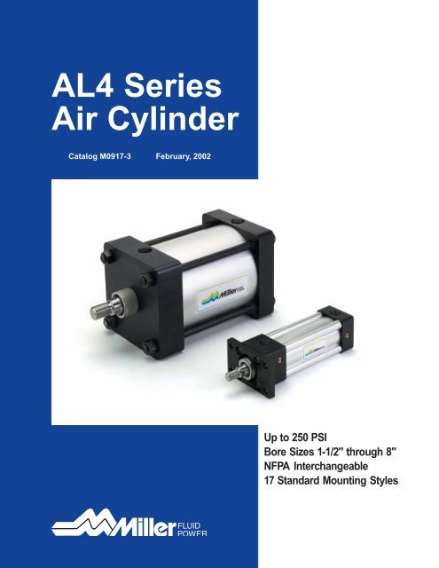
<strong>Miller</strong> <strong>AL4</strong> <strong>Series</strong>Air CylindersMounting StylesMounting Styles That Fit Your Installation Requirement<strong>Miller</strong> <strong>AL4</strong> <strong>Series</strong> air cylinders operate at internal pressures up to 250 PSI, and incorporate proven <strong>Miller</strong> designcharacteristics to provide safe, reliable power for many heavy-duty industrial applications. Available in 17 standardmounting configurations to provide centerline, foot or pivot installations as explained below.Centerline MountingThe preferred cylinder installationmethod, centerline mounting placesthe mounting bolts in simple shearor simple tension so that the mountingmechanism is protected fromcompound forces. Centerlinemounting is a rigid mounting styleand this requires accurate cylinderalignment to prevent damage to thecylinder working parts.<strong>Miller</strong> <strong>AL4</strong> mounting configurationsthat provide centerline supportinclude: tie rod mounts (51, 52, 53),and flange mounts with rectangularflanges affixed to the head or capend of the cylinder (61 and 62).Foot MountingFoot mounting allows the cylinder tobe mounted and secured along itsside, on both the head and cap end.When considering this style ofmount, it should be noted that themounting surface plane is not trulycentered with the line of force plane.Therefore, the mounting bolts maybe subjected to a significant amountof shear stress. Foot mounts arerigid in nature. Accurate cylinderalignment must be practiced whenselecting this type of mount.<strong>Miller</strong> <strong>AL4</strong> <strong>Series</strong> mounting configurationsthat provide foot mountingsare: side end angle (71), side lug(72), and side tap (74). Side tapmounting incorporates flush, tappedmounting holes on the head and capof the cylinder providing an alternativeto side lugs and foot brackets.Pivot MountingPivot mounting is used when thecylinder must pivot during pistonmotion. Clevis and trunnion mountsare the two methods used to allowthis motion.The clevis end design locates thepivot point at the cap end of thecylinder (84, 86, 96). Trunnionmounting allows pivoting of thecylinder via the head or cap (81, 82),or intermediate location (89). Bothclevis and trunnion mount configurationsallow the cylinder to pivot inone plane only.Centerline mounting is preferablesince it prevents compound forcesfrom acting on the mounting bolts(flange model shown).Foot mounting secures the cylinderon its side, but can subject themounting bolts to compound stress(cylinder side lugs shown).Pivot mounting allows the cylinder topivot during piston motion (clevismethod shown).4
<strong>Miller</strong> <strong>AL4</strong> <strong>Series</strong>Air CylindersStandard Specifications & Mounting StylesStandard Specifications• N.F.P.A. Interchangeable• Bore sizes – 1-1/2", 2", 2-1/2", 3-1/4" and 4"• Rod Diameters – 5/8", 1", and 1-3/8"• Rod Ends – three standard, specials to order.• Cushions – optional at either end or both endsof stroke• Strokes – available in any practical stroke length.• 250 P.S.I. Air Service/Optional 250 P.S.I.,Hydraulic Service (non-cushioned only).Available Mounting StylesTie Rods Extended Both Ends Tie Rods Extended Cap End Tie Rods Extended Head End Head Rectangular FlangeModel 511 1 /2 -4"Model 521 1 /2 -4"• Standard Fluid – Filtered Air• Standard Temperature – -10°F to +165°F• Fluorocarbon Seals for high temperature service –-10°F to +250°F (optional)• Single rod end or double rod end• Mounting styles – 17 standard• Optional noise damping bumpers• Non-LubeModel 531 1 /2 -4"Model 61*1 1 /2 -4"(NFPA MX1)(NFPA MX2)(NFPA MX3)(NFPA MF1)Cap Rectangular Flange No Mount Side End Angle Side LugModel 62*1 1 /2 -4"Model 501 1 /2 -4"Model 71*1 1 /2 -4"Model 721 1 /2 -4"(NFPA MF2)(NFPA MX0)(NFPA MS1)(NFPA MS2)Side Tap Head Trunnion Cap Trunnion Intermediate TrunnionModel 741 1 /2 -4"Model 811 1 /2 -4"Model 821 1 /2 -4"Model 89 ▲1 1 /2 -4"(NFPA MS4)(NFPA MT1)(NFPA MT2)(NFPA MT4)Cap Fixed Clevis Cap Detachable Clevis Cap Detachable EyeModel 84*1 1 /2 -4"Model 86*1 1 /2 -4"Model 96*1 1 /2 -4"Side End LugModel 771 1 /2 -4"(NFPA MP1)(NFPA MP2)(NFPA MP4)(NFPA MS7)Sleeve NutModel 551 1 /2 -4"Rod End #1Double Rod EndModel D<strong>AL4</strong> Shown1 1 /2 -4"▲Tie Rod Design(NFPA MX5)(NFPA MDX0)Rod End #2*Indicates Bolt onMounting Design1 1 /2 -4" Bores5
<strong>Miller</strong> <strong>AL4</strong> <strong>Series</strong>Air CylindersNo Mount BasicModel 50(NFPA MX0)YNo Mount (Basic)Head Rectangular Flange MountCap Rectangular Flange Mount1-1/2" to 4" Bore SizesZJ + STROKEP + STROKEWFLF + STROKEEE1E SQ.42MMAA3R SQ.K1 G JHead Rectangular FlangeModel 61(NFPA MF1)ZJ + STROKEYP + STROKEWLB + STROKEUFEE1R142EMM3ETFFB4 HOLESFG JK1Cap Rectangular FlangeModel 62(NFPA MF2)ZF + STROKEYP + STROKEWFLB + STROKEEEUF1MMR1 24E3K1G JZJ + STROKEFETFFB4 HOLES6
<strong>Miller</strong> <strong>AL4</strong> <strong>Series</strong>Air CylindersRod End Dimensions—Basic CylinderD WRENCH FLATSFRONT FLANGEThread Style 2(NFPA Style SM)Small MaleAKKCLAFLAWWFVFNA MM BFThread Style 5(NFPA Style IM)Intermediate MaleNAD WRENCH FLATSFRONT FLANGEIMACLAFLAWWFVFFMM BD WRENCH FLATSThread Style 4(NFPA Style SF)Short FemaleNAFRONT FLANGEKKCLAWFAWVFNo Mount (Basic)Head Rectangular Flange MountCap Rectangular Flange Mount1-1/2" to 4" Bore SizesFMM B“SpecialThread”Style XSpecial thread,extension, rod eye,blank, etc., arealso available.To order specify“Style X” and givedesired dimensionsfor KK, Aand W or WF. Ifotherwise special,furnish dimensionedsketch.Table 1—Envelope and Mounting DimensionsBore AA EEE(NPTF)F FB G J K1 R R1 TF UFADD STROKELB LF P1 1 / 2 2.02 2 3/ 83/ 85/ 16 1 7 / 16 15/ 161/ 8 1.43 1.43 2 3 / 4 3 3 / 8 4 3 5 / 8 2 5 / 162 2.6 2 1 /2 3/8 3/8 3/8 1 7 /16 15/16 5/32 1.84 1.84 3 3 /8 4 1 /8 4 3 5 /8 2 5 /162 1 / 2 3.1 3 3/ 8 3/ 8 3/ 8 111/ 16 15/ 16 5/ 32 2.19 2.19 33/ 8 45/ 8 41/ 8 33/ 4 23/ 83 1 / 4 3.9 3 3 / 41/ 25/ 87/ 16 1 11 / 16 1 3 / 163/ 16 2.76 2.76 4 11 / 16 5 1 / 2 4 7 / 8 4 1 / 4 2 5 / 84 4.7 4 1 /2 1/2 5/8 7/16 1 11 /16 1 3 /16 3/16 3.32 3.32 5 7 /16 6 1 /4 4 7 /8 4 1 /4 2 5 /8Table 2—Rod DimensionsRod5/ 8 1/ 2-201 1 / 21* 7/8-145/ 8 1/ 2-2021 7/ 8-145/ 8 1/ 2-202 1 /21 7/ 8-141 7/ 8-143 1 / 41 3 /8 1 1 /4-121 7/ 8-1441 3 /8 1 1 / 4-12*Cushion not available head end.ThreadStyle Style +.000Bore Dia 5 2 & 4 -.002Size MM IM KK A B C D LA NA VF W WF Y7/ 16-203/ 4-167/ 16-203/ 4-167/16-203/ 4-163/ 4-161-143/ 4-161-143/ 4 1.1241 1 / 8 1.4993/ 4 1.1241 1 / 8 1.4993/4 1.1241 1 / 8 1.4991 1 / 8 1.4991 5 / 8 1.9991 1 / 8 1.4991 5 / 8 1.9993/ 81/ 23/ 81/ 23/81/ 21/ 25/ 81/ 25/ 81/ 27/ 81/ 27/ 81/27/ 87/ 81 1 / 87/ 81 1 / 81 3 / 82 1 / 81 3 / 82 1 / 81 3 /82 1 / 81 7 / 82 5 / 81 7 / 82 5 / 89/ 1615/ 169/ 1615/ 169/1615/ 1615/ 161 5 / 1615/ 161 5 / 165/ 87/ 85/ 87/ 85/87/ 87/ 817/ 815/ 815/ 815/813/ 413/ 41ZF1 1 7 / 8 51 5 / 8 2 11 / 16 6 1 / 21 3 / 8 2 1 / 4 5 3 / 81 1 7 / 8 51 3 / 8 2 1 / 4 5 3 / 81 1 15 /16 5 1 /81 3 / 8 2 5 / 16 5 1 / 21 3 / 8 2 7 / 16 6 1 / 41 5 / 8 2 11 / 16 6 1 / 21 3 / 8 2 7 / 16 6 1 / 4Table 3–Envelopeand MountingDimensionsADD STROKEZJ4 5 / 854 5 / 854 3 /45 1 / 85 5 / 85 7 / 85 5 / 85 7 / 87
<strong>Miller</strong> <strong>AL4</strong> <strong>Series</strong>Air CylindersTie Rods Extended Head End MountTie Rods Extended Cap End MountTie Rods Extended Both Ends MountSleeve Nut Mount1-1/2" to 4" Bore SizesTie Rods Extended Head End MountModel 53(NFPA MX3)DDWFYZJ + STROKEP + STROKELF + STROKEEE1E SQ. 42MMAA3R SQ.KBBG JK1Tie Rods Extended Cap End MountModel 52(NFPA MX2)WFYZJ + STROKEP + STROKELF + STROKEEEDD1E SQ. 42MMAA3R SQ.KK1G J BBTie Rods Extended Both Ends MountModel 51(NFPA MX1)DDWFYZJ + STROKEP + STROKELF + STROKEEEDD1E SQ. 42MMAA3R SQ.KKBBG JBBSleeve Nut MountModel 55(NFPA MX5)YZJ + STROKEP + STROKEWFLF + STROKEDDEE1ESQ.42MMAA3R SQ.BGGJBG8
<strong>Miller</strong> <strong>AL4</strong> <strong>Series</strong>Air CylindersRod End Dimensions—Basic CylinderD WRENCH FLATSThread Style 2(NFPA Style SM)Small MaleACKKLAFWFVFNA MM BD WRENCH FLATSThread Style 5(NFPA Style IM)Intermediate MaleIMACLAFWFVFNA MM BD WRENCH FLATSThread Style 4(NFPA Style SF)Short FemaleKKCTie Rods Extended Head End MountTie Rods Extended Cap End MountTie Rods Extended Both Ends MountSleeve Nut Mount1-1/2" to 4" Bore SizesWFVFNA MM BA“SpecialThread”Style XSpecial thread,extension, rod eye,blank, etc., arealso available.To order specify“Style X” and givedesired dimensionsfor KK, Aand W or WF. Ifotherwise special,furnish dimensionedsketch.Table 1—Envelope and Mounting DimensionsBore AA BB BG DD E11/ 2 2.022 2.62 1 / 2 3.13 1 / 4 3.94 4.71 .45 1/ 4-28 121 1 /81 1 / 81 3 / 81 3 /8.48 5/16-24.48 5/ 16-24.50 3/ 8-24.50 3/8-242 1 /233 3 / 44 1 /2EE(NPTF)G J K K1 R3/ 8 1 7 /1615/ 16 1/ 4 1/ 8 1.431/ 2 1 11 / 16 1 3 / 16 3/ 8 3/ 16 3.323/ 8 1 7 / 1615/ 16 5/ 16 5/ 32 1.843/ 8 1 7 / 1615/ 16 5/ 16 5/ 32 2.191/ 2 1 11 /16 1 3 / 16 3/ 8 3/ 16 2.76ADD STROKELF3 5 / 83 5 / 83 3 / 44 1 / 44 1 / 4P2 5 /162 5 / 162 3 / 82 5 / 82 5 / 8Table 2—Rod DimensionsTable 3–Envelope andMounting DimensionsRod ThreadADDStyle Style +.000STROKEBore Dia 5 2 &4 -.002Size MM IM KK A B C D LAF NA VF W WF Y ZJ11/ 222 1 / 23 1 / 445/ 8 1/ 2-20 7 / 16-20 3/ 4 1.124 3/ 8 1/ 2 1 3 / 4 9/ 16 5/ 8 5/ 8 1 1 7 / 8 4 5 / 81* 7/ 8-14 3 / 4-16 1 1 / 8 1.499 1/ 2 7/ 8 2 1 / 215/ 16 7/ 8 1 1 3 / 8 2 1 / 4 55/ 8 1/ 2-20 7 / 16-20 3/ 4 1.124 3/ 8 1/ 2 1 3 / 4 9/ 16 5/ 8 5/ 8 1 1 7 / 8 4 5 / 81 7/ 8-14 3 / 4-16 1 1 / 8 1.499 1/ 2 7/ 8 2 1 / 215/ 16 7/ 8 1 1 3 / 8 2 1 / 4 55/ 8 1/ 2-20 7 / 16-20 3/ 4 1.124 3/ 8 1/ 2 1 3 / 4 9/ 16 5/ 8 5/ 8 1 1 15 / 16 4 3 / 41 7/ 8-14 3 / 4-16 1 1 / 8 1.499 1/ 2 7/ 8 2 1 / 215/ 16 7/ 8 1 1 3 / 8 2 5 / 16 5 1 / 81 7/ 8-14 3 / 4-16 1 1 / 8 1.499 1/ 2 7/ 8 2 1 / 215/ 16 7/ 8 3/ 4 1 3 / 8 2 7 / 16 5 5 / 81 3 / 8 1 1 / 4-12 1-14 1 5 / 8 1.999 5/ 8 1 1 / 8 3 1 / 4 1 5 / 16 1 1 1 5 / 8 2 11 / 16 5 7 / 81 7/ 8-14 3 / 4-16 1 1 / 8 1.499 1/ 2 7/ 8 2 1 / 215/ 16 7/ 8 3/ 4 1 3 / 8 2 7 / 16 5 5 / 81 3 / 8 1 1 / 4-12 1-14 1 5 / 8 1.999 5/ 8 1 1 / 8 3 1 / 4 1 5 / 16 1 1 1 5 / 8 2 11 / 16 5 7 / 8*Cushion not available head end.9
<strong>Miller</strong> <strong>AL4</strong> <strong>Series</strong>Air CylindersSide End Angle MountSide End Lug MountSide Lug MountSide Tap Mount1-1/2" to 4" Bore SizesSide End Angle MountModel 71*(NFPA MS1)EWFK1YZA + STROKEXA + STROKEP + STROKELF + STROKEEEAB6 HOLES4E31MMS.1252.125*Maximum recommendedpressure of 150 PSIAHAO AL FAEG JSA + STROKEAL 1 AOZE + STROKESide End Lug MountXE + STROKEModel 77YP + STROKE(NFPA MS7) LF + STROKE1WFK1EEE SQ.42MMETGHEB4 HOLESET3RETG JEO EM ELEOSE + STROKESide Lug MountModel 72(NFPA MS2)EYWFZJ + STROKEP + STROKELF + STROKEEEK11SB4 HOLESE42MMSTLH3SWSWTSSWSWG JUSSWSWXSSS + STROKESide Tap Mount*Model 74(NFPA MS4)WFYZJ + STROKEP + STROKELF + STROKEK1EE1E SQ.42MMTH3*Not available in 1-1/2" bore, 1" rod.TNNT THREAD, ND DEEP4 TAPPED MTG. HOLESG JXT SN + STROKE10
<strong>Miller</strong> <strong>AL4</strong> <strong>Series</strong>Air CylindersRod End Dimensions—Basic CylinderD WRENCH FLATSThread Style 2(NFPA Style SM)Small MaleACKKLAFWFVFNA MM BD WRENCH FLATSThread Style 5(NFPA Style IM)Intermediate MaleIMACLAFWFVFNA MM BD WRENCH FLATSThread Style 4(NFPA Style SF)Short FemaleKKCWFVFNA MM BASide End Angle MountSide End Lug MountSide Lug MountSide Tap Mount1-1/2" to 4" Bore Sizes“SpecialThread”Style XSpecial thread,extension, rod eye,blank, etc., arealso available.To order specify“Style X” and givedesired dimensionsfor CC orKK, A and W orWF. If otherwisespecial, furnishdimensionedsketch.Table 1—Envelope and Mounting DimensionsADD STROKEBore AB AE AH AL AL1 AO E EE EB EL EM EO ET F G GH J K1 LH NT S ST SW TH TN TS US(NPTF) ±.003±.003 ±.003LF P SA SE SN SS11/ 2 7/ 16 1 3 / 8 1 3 / 16 1 1 3/ 8 2 3/ 8 9/ 32 3/ 4 1 1 / 8 1/ 4 9/ 16 3/ 8 1 7 / 16 .993 15 / 16 1/ 8 .993 1 / 4-20 1 1 / 4 1/ 2 3/ 8 .993 5/ 8 2 3 / 4 3 1 / 2 3 5 / 8 2 5 / 16 6 5 1 / 2 2 1 / 4 2 7 / 82 7/ 16 1 3 / 8 1 7 / 16 1 1 3/ 8 2 1 / 2 3/ 811/ 3215/ 16 1 5 / 16 5/ 1611/ 16 3/ 8 1 7 / 16 1.243 15 / 16 5/ 32 1.243 5 / 16-18 1 3 / 4 1/ 2 3/ 8 1.243 7 / 8 3 1 / 4 4 3 5 / 8 2 5 / 16 6 5 7 / 8 2 1 / 4 2 7 / 82 1 / 2 7/ 16 1 3 / 8 1 5 / 8 1 1 3/ 8 3 3/ 8 11/ 32 1 1 / 16 1 7 / 16 5/ 16 13/ 16 3/ 8 1 7 / 16 1.493 15 / 16 5/ 32 1.493 3 / 8-16 2 1 / 4 1/ 2 3/ 8 1.493 1 1 / 4 3 3 / 4 4 1 / 2 3 3 / 4 2 3 / 8 6 1 / 8 6 1 / 4 2 3 / 8 33 1 / 4 9/ 16 1 7 / 8 1 15 / 16 1 1 / 4 1 1 / 4 1/ 2 3 3 / 4 1/ 2 13/ 32 7/ 8 11/ 2 3/ 8 1 5/ 8 1 11 / 16 1.868 1 3 / 16 3/ 16 1.868 1 / 2-13 2 3 / 4 3/ 4 1/ 2 1.868 1 1 / 2 4 3 / 4 5 3 / 4 4 1 / 4 2 5 / 8 7 3 / 8 6 5 / 8 2 5 / 8 3 1 / 44 9/16 – 2 1 /4 1 7 /8 1 1 /4 1/2 4 1 /2 1/2 13/32 1 1 5 /8 3/8 1 3 /16 – 1 11 /16 2.243 1 3 /16 3 /16 2.243 1 /2-13 3 1 /2 3 /4 1/2 2.243 2 1 /16 5 1 /2 6 1 /2 4 1 /4 2 5 /8 7 3 /8 6 7 /8 2 5 /8 3 1 /4Table 2—Rod DimensionsTable 3–Envelope andMounting DimensionsRodThreadADD STROKEStyle Style +.000Bore Dia 5 2 & 4 -.002Size MM IM KK A B C D LAF NA VF W WF Y ND XS XT XA XE ZA ZE ZJ1 1 /222 1 / 23 1 /445/ 8 1/ 2-20 7 / 16-20 3 / 4 1.124 3/ 8 1/ 2 1 3 / 4 9/ 16 5/ 8 5/ 8 1 1 7 / 8 3/ 8 1 3 / 8 1 15 / 16 5 5 / 8 5 3 / 8 6 5 5 / 8 4 5 / 81* 7/ 8-14 3/ 4-16 1 1 / 8 1.499 1/ 2 7/ 8 2 1 / 2 15/ 16 7/ 8 1 1 3 / 8 2 1 / 4 – 1 3 / 4 – 6 – 6 3 / 8 – 55/ 8 1/ 2-20 7 / 16-20 3 / 4 1.124 3/ 8 1/ 2 1 3 / 4 9/ 16 5/ 8 5/ 8 1 1 7 / 8 7/ 16 1 3 / 8 1 15 / 16 5 5 / 8 5 9 / 16 6 5 7 / 8 4 5 / 81 7/ 8-14 3/ 4-16 1 1 / 8 1.499 1/ 2 7/ 8 2 1 / 2 15/ 16 7/ 8 1 1 3 / 8 2 1 / 4 7/ 16 1 3 / 4 2 5 / 16 6 5 15 / 16 6 3 / 8 6 1 / 4 55/8 1/2-20 7 /16-20 3 /4 1.124 3/8 1/2 1 3 /4 9/16 5/8 5/8 1 1 15 /16 5/8 1 3 /8 1 15 /16 5 3 /4 5 13 /16 6 1 /8 6 1 /8 4 3 /41 7/ 8-14 3/ 4-16 1 1 / 8 1.499 1/ 2 7/ 8 2 1 / 215/ 16 7/ 8 1 1 3 / 8 2 5 / 16 5/ 8 1 3 / 4 2 5 / 16 6 1 / 8 6 3 / 16 6 1 / 2 6 1 / 2 5 1 / 81 7/ 8-14 3/ 4-16 1 1 / 8 1.499 1/ 2 7/ 8 2 1 / 215/ 16 7/ 8 3/ 4 1 3 / 8 2 7 / 16 3/ 4 1 7 / 8 2 7 / 16 6 7 / 8 6 1 / 2 7 3 / 8 6 7 / 8 5 5 / 81 3 / 8 1 1 / 4-12 1-14 1 5 / 8 1.999 5/ 8 1 / 8 3 1 / 4 1 5 / 16 1 1 1 5 / 8 2 11 / 16 3/ 4 2 1 / 8 2 11 / 16 7 1 / 8 6 3 / 4 7 5 / 8 7 1 / 8 5 7 / 81 7/ 8-14 3 / 4-16 1 1 / 8 1.499 1/ 2 7/ 8 2 1 / 2 15/ 16 7/ 8 3/ 4 1 3 / 8 2 7 / 16 3/ 4 1 7 / 8 2 7 / 16 6 7 / 8 6 5 / 8 7 3 / 8 7 5 5 / 81 3 / 8 1 1 / 4-12 1-14 1 5 / 8 1.999 5/ 8 1 / 8 3 1 / 4 1 5 / 16 1 1 1 5 / 8 2 11 / 16 3/ 4 2 1 / 8 2 11 / 16 7 1 / 8 6 7 / 8 7 5 / 8 7 1 / 4 5 7 / 8*Cushion not available head end.11
<strong>Miller</strong> <strong>AL4</strong> <strong>Series</strong>Air CylindersCap Fixed Clevis MountCap Detachable Clevis MountCap Detachable Eye Mount1-1/2" to 4" Bore SizesCap Fixed Clevis MountModel 84(NFPA MP1)YZC + STROKEP + STROKEWFLB + STROKEK1EEE SQ.CD1MRMM24LRG JFLCW3CBCWXC + STROKEFor maximum swivel angle with rear mounting plate for “84” mounting see <strong>AL4</strong> <strong>Series</strong> cylinder accessories.Cap Detachable Clevis MountModel 86(NFPA MP2)WFYZD1 + STROKEP + STROKELB + STROKEEECD E SQ.1MM24MR13K1G JFL1CWCBCWXD + STROKECap Detachable Eye MountModel 96(NFPA MP4)YZD2 + STROKEP + STROKEWFLB + STROKEK1EECD1E SQ.1MM24MR2KG JFL13CBXD + STROKE12
<strong>Miller</strong> <strong>AL4</strong> <strong>Series</strong>Air CylindersRod End Dimensions—Basic CylinderD WRENCH FLATSThread Style 2(NFPA Style SM)Small MaleACKKLAFWFVFNA MM BD WRENCH FLATSThread Style 5(NFPA Style IM)Intermediate MaleIMACLAFWFVFNA MM BD WRENCH FLATSThread Style 4(NFPA Style SF)Short FemaleKKCWFVFNA MM BACap Fixed Clevis MountCap Detachable Clevis MountCap Detachable Eye Mount1-1/2" to 4" Bore Sizes“SpecialThread”Style XSpecial thread,extension, rod eye,blank, etc., arealso available.To order specify“Style X” and givedesired dimensionsfor KK, Aand W or WF. Ifotherwise special,furnish dimensionedsketch.Table 1—Envelope and Mounting Dimensions+.000 +.002Bore CB CD CD 1CW E EE F G J K1 L L1 LR MR MR1 MR2-.002 +.004(NPTF)ADD STROKELB P1 1 /2 3/4 .501 .500 1/2 2 3/8 3/8 1 7 /16 15/16 1/8 3/8 3/4 3/4 5/8 1/2 5/8 4 2 5 /162 3/ 4 .501 .500 1/ 2 2 1 / 2 3/ 8 3/ 8 1 7 / 16 15/ 16 5/ 32 3/ 8 3/ 4 3/ 4 5/ 8 1/ 2 5/ 8 4 2 5 / 162 1 / 23/ 4 .501 .500 1/ 2 3 3/ 8 3/ 8 1 7 / 1615/ 16 5/ 32 3/ 8 3/ 4 3/ 4 5/ 8 1/ 211/ 16 4 1 / 8 2 3 / 83 1 /4 1 1 /4 .751 .750 5/8 3 3 /4 1/2 5/8 1 11 /16 1 3 /16 3/16 5/8 1 1 /4 1 15/16 3/4 7/8 4 7 /8 2 5 /84 1 1 / 4 .751 .750 5/ 8 4 1 / 2 1/ 2 5/ 8 1 11 / 16 1 3 / 16 3/ 16 5/ 8 1 1 / 4 1 15/ 16 3/ 4 7/ 8 4 7 / 8 2 5 / 8Table 2—Rod DimensionsTable 3–Envelope andMounting DimensionsRod ThreadADD STROKEStyle Style +.000Bore Dia 5 2 & 4 -.002Size MM IM KK A B C D LAF NA VF W WF Y XC XD ZC ZD1 ZD211/ 222 1 / 23 1 / 445/ 8 1/ 2-20 7 / 16-20 3 / 4 1.124 3/ 8 1/ 2 1 3 / 4 9/ 16 5/ 8 5/ 8 1 1 7 / 8 5 3 / 8 5 3 / 4 6 6 1 / 4 6 3 / 81* 7/ 8-14 3 / 4-16 1 1 / 8 1.499 1/ 2 7/ 8 2 1 / 215/ 16 7/ 8 1 1 3 / 8 2 1 / 4 5 3 / 4 6 1 / 8 6 3 / 8 6 5 / 8 6 3 / 45/ 8 1/ 2-20 7 / 16-20 3 / 4 1.124 3/ 8 1/ 2 1 3 / 4 9/ 16 5/ 8 5/ 8 1 1 7 / 8 5 3 / 8 5 3 / 4 6 6 1 / 4 6 3 / 81 7/ 8-14 3 / 4-16 1 1 / 8 1.499 1/ 2 7/ 8 2 1 / 215/ 16 7/ 8 1 1 3 / 8 2 1 / 4 5 3 / 4 6 1 / 8 6 3 / 8 6 5 / 8 6 3 / 45/ 8 1/ 2-20 7 / 16-20 3 / 4 1.124 3/ 8 1/ 2 1 3 / 4 9/ 16 5/ 8 5/ 8 1 1 15 / 16 5 1 / 2 5 7 / 8 6 1 / 8 6 3 / 8 6 9 / 161 7/ 8-14 3 / 4-16 1 1 / 8 1.499 1/ 2 7/ 8 2 1 / 215/ 16 7/ 8 1 1 3 / 8 2 5 / 16 5 7 / 8 6 1 / 4 6 1 / 2 6 3 / 4 6 15 / 161 7/ 8-14 3 / 4-16 1 1 / 8 1.499 1/ 2 7/ 8 2 1 / 215/ 16 7/ 8 3/ 4 1 3 / 8 2 7 / 16 6 7 / 8 7 1 / 2 7 13 / 16 8 1 / 4 8 3 / 81 3 / 8 1 1 / 4-12 1-14 1 5 / 8 1.999 5/ 8 1 1 / 8 3 1 / 4 1 5 / 16 1 1 1 5 / 8 2 11 / 16 7 1 / 8 7 3 / 4 8 1 / 16 8 1 / 2 8 5 / 81 7/ 8-14 3 / 4-16 1 1 / 8 1.499 1/ 2 7/ 8 2 1 / 215/ 16 7/ 8 3/ 4 1 3 / 8 2 7 / 16 6 7 / 8 7 1 / 2 7 13 / 16 8 1 / 4 8 3 / 81 3 / 8 1 1 / 4-12 1-14 1 5 / 8 1.999 5/ 8 1 1 / 8 3 1 / 4 1 5 / 16 1 1 1 5 / 8 2 11 / 16 7 1 / 8 7 3 / 4 8 1 / 16 8 1 / 2 8 5 / 8*Cushion not available head end.13
<strong>Miller</strong> <strong>AL4</strong> <strong>Series</strong>Air CylindersHead Trunnion Mount*Model 81(NFPA MT1)YHead Trunnion MountCap Trunnion MountIntermediate Trunnion Mount1-1/2" to 4" Bore SizesZJ + STROKEP + STROKEWFLF + STROKEUTEE1E42MMTD3TL ETLG JK1XG*Not available in 1-1/2" bore, 1" rod.Cap Trunnion MountModel 82(NFPA MT2)WFYZJ + STROKEP + STROKELF + STROKEK1UTEE1E42MMTD3TL ETLG JXJ + STROKEIntermediate Trunnion MountModel 89(NFPA MT4)YZJ + STROKEP + STROKEUM1WFLF + STROKEEEBDUV42MMTD3E SQ.G JKTLTM TLXI▲ Dimension “Xl” to be specified by customer.14
<strong>Miller</strong> <strong>AL4</strong> <strong>Series</strong>Air CylindersRod End Dimensions—Basic CylinderD WRENCH FLATSThread Style 2(NFPA Style SM)Small MaleACKKLAFWFVFNA MM BD WRENCH FLATSThread Style 5(NFPA Style IM)Intermediate MaleIMACLAFWFVFNA MM BD WRENCH FLATSThread Style 4(NFPA Style SF)Short FemaleKKCWFVFNA MM BAHead Trunnion MountCap Trunnion MountIntermediate Trunnion Mount1-1/2" to 4" Bore Sizes“SpecialThread”Style XSpecial thread,extension, rod eye,blank, etc., arealso available.To order specify“Style X” and givedesired dimensionsfor KK, Aand W or WF. Ifotherwise special,furnish dimensionedsketch.Table 1—Envelope and Mounting Dimensions+.000ADD STROKEBore BD E EE G J K K1 TD TL TM UM UT UV(NPTF)-.001LF PStyle MT4MinimumStroke1 1 /2 1 1 /4 2 3/8 1 7 /16 15 /16 1/4 1/8 1.000 1 2 1 /2 4 1 /2 4 2 1 /2 3 5 /8 2 5 /16 02 11/ 2 2 1 / 2 3/ 8 1 7 / 16 15/ 16 5/ 16 5/ 32 1.000 1 3 5 4 1 / 2 3 3 5 / 8 2 5 / 16 1/ 42 1 / 2 1 1 / 2 3 3/ 8 1 7 / 1615/ 16 5/ 16 5/ 32 1.000 1 3 1 / 2 5 1 / 2 5 3 1 / 2 3 3 / 4 2 3 / 8 1/ 83 1 /4 2 3 3 /4 1/2 1 11 /16 1 3 /16 3/8 3/16 1.000 1 4 1 /2 6 1 /2 5 3 /4 4 1 /4 4 1 /4 2 5 /8 5/84 2 4 1 / 2 1/ 2 1 11 / 16 1 3 / 16 3/ 8 3/ 16 1.000 1 5 1 / 4 7 1 / 4 6 1 / 2 5 4 1 / 4 2 5 / 8 5/ 8Table 2—Rod DimensionsTable 3–Envelope andMounting DimensionsRod Thread▲ADD STROKEBore DiaStyle5Style2 & 4+.000-.002Min.Size MM IM KK A B C D LAF NA VF W WF Y XG XI XJ ZJ1 1 / 25/ 8 1/ 2-20 7 / 16-20 3 / 4 1.124 3/ 8 1/ 2 1 3 / 4 9/ 16 5/ 8 5/ 8 1 1 7 / 8 1 3 / 4 3 3 / 16 4 1 / 8 4 5 / 81* 7/ 8-14 3/ 4-16 1 1 / 8 1.499 1/ 2 7/ 8 2 1 / 2 15/ 16 7/ 8 1 1 3 / 8 2 1 / 4 – 3 11 / 16 4 1 / 2 522 1 / 23 1 / 445/ 8 1/ 2-20 7 / 16-20 3 / 4 1.124 3/ 8 1/ 2 1 3 / 4 9/ 16 5/ 8 5/ 8 1 1 7 / 8 1 3 / 4 3 5 / 16 4 1 / 8 4 5 / 81 7/ 8-14 3/ 4-16 1 1 / 8 1.499 1/ 2 7/ 8 2 1 / 2 15/ 16 7/ 8 1 1 3 / 8 2 1 / 4 2 1 / 8 3 11 / 16 4 1 / 2 55/ 8 1/ 2-20 7 / 16-20 3 / 4 1.124 3/ 8 1/ 2 1 3 / 4 9/ 16 5/ 8 5/ 8 1 1 15 / 16 1 3 / 4 3 5 / 16 4 1 / 4 4 3 / 41 7/ 8-14 3/ 4-16 1 1 / 8 1.499 1/ 2 7/ 8 2 1 / 2 15/ 16 7/ 8 1 1 3 / 8 2 5 / 16 2 1 / 8 3 11 / 16 4 5 / 8 5 1 / 81 7/ 8-14 3/ 4-16 1 1 / 8 1.499 1/ 2 7/ 8 2 1 / 2 15/ 16 7/ 8 3/ 4 1 3 / 8 2 7 / 16 2 1 / 4 4 3 / 16 5 5 5 / 81 3 / 8 1 1 / 4-12 1-14 1 5 / 8 1.999 5/ 8 1 1 / 8 3 1 / 4 1 5 / 16 1 1 1 5 / 8 2 11 / 16 2 1 / 2 4 7 / 16 5 1 / 4 5 7 / 81 7/ 8-14 3/ 4-16 1 1 / 8 1.499 1/ 2 7/ 8 2 1 / 2 15/ 16 7/ 8 3/ 4 1 3 / 8 2 7 / 16 2 1 / 4 4 3 / 16 5 5 5 / 81 3 / 8 1 1 / 4-12 1-14 1 5 / 8 1.999 5/ 8 1 1 / 8 3 1 / 4 1 5 / 16 1 1 1 5 / 8 2 11 / 16 2 1 / 2 4 7 / 16 5 1 / 4 5 7 / 8*Cushion not available head end.▲ Dimension “Xl” to be specified by customer.15
<strong>Miller</strong> <strong>AL4</strong> <strong>Series</strong>Air CylindersDouble Rod Models1-1/2" to 4" Bore SizesHow to Use Double Rod CylinderDimensioned DrawingsTo determine dimensions for a double rod cylinder,first refer to the desired single rod mounting stylecylinder shown on preceding pages of this catalog.After selecting necessary dimensions from thatdrawing, return to this page and supplement thesingle rod dimensions with those shown on thedrawing and dimension table below. Note that doublerod cylinders have a head (Dim. G) at both ends andthat dimension LG replaces LF and PK replaces P,etc. The double rod dimensions differ from, or arein addition to those for single rod cylinders shownon preceding pages and provide the informationneeded to completely dimension a double rodcylinder.On a double rod cylinder where the two rod endsare different, be sure to clearly state which rodend is to be assembled at which end.ZM + 2 X STROKEYPK + STROKEWFLG + STROKEEEK1MMROD END #1 ROD END #2GGAll dimensions are in inches and apply to standard rod sizes only. For alternate rodsizes, determine all envelope dimensions (within LD dim.) as described above andthen use appropriate rod end dimensions for proper rod size from single rod cylinder.RodAddDia.ADD STROKE2xBoreStrokeMM LG PK SAK XAK SSK SNK SEK XEK ZM1 / 2 5 / 8 4 1 / 8 2 3 / 8 6 1 / 8 6 1 / 8 3 3 / 8 2 1 / 4 6 3 / 8 6 1 / 4 6 1 / 82 5/ 8 41/ 8 23/ 8 61/ 8 61/ 8 33/ 8 21/ 4 63/ 4 67/ 16 61/ 82 1 /2 5/8 4 1 /4 2 3 /8 6 1 /4 6 1 /4 3 1 /2 2 3 /8 7 1 /8 6 11 /16 6 1 /43 1 / 4 1 4 3 / 4 2 5 / 8 7 1 / 4 7 3 / 8 3 3 / 4 2 5 / 8 7 3 / 4 7 5 / 8 7 1 / 24 1 43/ 4 25/ 8 71/ 4 73/ 8 33/ 4 25/ 8 8 73/ 4 71/ 2REPLACES DIMENSION LF P SA XA SS SN SE XE –ON SINGLE RODMOUNTING STYLESALL MTGSTYLES7172 74 77ALL MTGSTYLES16
<strong>Miller</strong> <strong>AL4</strong> <strong>Series</strong>Air CylindersRod End Dimensions—Basic CylinderD WRENCH FLATSThread Style 2(NFPA Style SM)Small MaleACKKLAFWFVFNA MM BD WRENCH FLATSThread Style 5(NFPA Style IM)Intermediate MaleIMACLAFWFVFNA MM BD WRENCH FLATSThread Style 4(NFPA Style SF)Short FemaleKKCWFVFNA MM BABushing DimensionsCylinder Weight Chart“SpecialThread”Style XSpecial thread,extension, rod eye,blank, etc., arealso available.To order specify“Style X” and givedesired dimensionsfor KK, Aand W or WF. Ifotherwise special,furnish dimensionedsketch.Table 2—Rod DimensionsRod ThreadStyle Style +.000Bore Dia 5 2 & 4 -.002Size MM IM KK A B C D LA NA VF W WF Y5/ 8 1/ 2-20 7/ 16-20 3/ 4 1.124 3/ 8 1/ 2 1 3 / 8 9/ 16 5/ 8 5/ 8 1 1 7 /41 7/8-14 3/ 4-16 1 1 / 8 1.499 1/ 2 7/ 8 1 7 / 8 15/ 16 7/ 8 3/ 4 1 3 / 8 2 7 / 161 3 / 8 1 1 / 4-12 1-14 1 5 / 8 1.999 5/ 8 1 1 / 8 2 5 / 8 1 5 / 16 1 1 1 5 / 8 2 11 / 161 1 / 21* 7/8-14 3/ 4-16 1 1 / 8 1.499 1/ 2 7/ 8 2 1 / 8 15/ 16 7/ 8 1 1 3 / 882 1 / 422 1 /25/ 85/ 81/ 2-201/ 2-207/ 16-207/16-203/ 43/41.1241.1243/ 83/81/ 21/21 3 / 81 3 /89/ 169/165/ 85/85/ 85/8111 7 / 81 15 /16117/ 8-147/ 8-143/ 4-163/ 4-161 1 / 81 1 / 81.4991.4991/ 21/ 27/ 87/ 82 1 / 82 1 / 815/ 1615/ 167/ 87/ 8111 3 / 81 3 / 82 1 / 42 5 / 163 1 / 411 3 / 87/ 8-141 1 / 4-123/ 4-161-141 1 / 81 5 / 81.4991.9991/ 25/ 87/ 81 1 / 81 7 / 82 5 / 815/ 161 5 / 167/ 813/ 411 3 / 81 5 / 82 7 / 162 11 / 16*Cushion not available head end.Cylinder Weights–<strong>AL4</strong>, <strong>AL4</strong>H CylindersNo Mount Single Rod No Mount Double RodBore Rod Base Per Inch Base Per InchIn. In. Lbs. Lbs. Lbs. Lbs.1.50 .625 1.73 .20 2.16 .282.00 .625 2.40 .21 3.05 .302.00 1.00 2.99 .35 4.34 .582.50 .625 3.25 .23 3.96 .312.50 1.00 4.06 .37 5.74 .603.25 1.00 6.45 .42 7.65 .643.25 1.375 7.93 .62 11.46 1.054.00 1.00 8.80 .49 10.32 .714.00 1.375 10.29 .69 14.37 1.125.00 1.00 13.20 .61 15.84 .845.00 1.375 14.72 .81 18.89 1.246.00 1.375 20.50 .87 25.65 1.306.00 1.75 22.61 1.13 30.41 1.828.00 1.375 35.50 1.25 41.15 1.688.00 1.75 37.63 1.51 45.90 2.20Mounting Weight Adders by Model NumberBore 61, 62 81, 82 84 71, 77 89 96 72 86In. Lbs. Lbs. Lbs. Lbs. Lbs. Lbs. Lbs. Lbs.1.50 .51 .50 .15 .36 1.70 .23 .15 .202.00 .76 .50 .26 .65 2.38 .32 .15 .292.50 1.13 .50 .38 1.05 3.00 .42 .15 .413.25 2.76 .50 .98 1.38 5.35 1.26 .35 1.064.00 4.05 .50 1.35 2.20 6.75 1.62 .35 1.495.00 6.46 .50 1.20 4.29 8.77 N/A .57 2.416.00 10.74 1.22 2.91 5.88 15.52 N/A .69 11.388.00 N/A 1.22 2.91 7.84 25.01 N/A .67 17.3117
<strong>Miller</strong> <strong>AL4</strong> <strong>Series</strong> - 5" through 8" BoreLightweight, Non-LubePneumatic Cylinder.Premium Quality and Economy in one.Lightweight construction and solid Non-Lube designwith proven reliability make the <strong>AL4</strong> <strong>Series</strong> Cylinderthe high performance, long lasting, economical choicefor your air cylinder applications.Heads and Caps are precision,lightweight aluminum blocks thatare anodized for maximumcorrosion resistance.Extruded AluminumLightweight cylinder body:aluminum tube with steel tie rods.PistonAluminum piston with nylon wearband increases cylinder life, eliminatesmetal-to-metal contact. Optionalmagnet* piston for use with reedor solid state switches. Anaerobicadhesive is used to permanently lockand seal the piston to the rod.* Magnet option must be specified when placingorder or piston will be equipped with wearband and seals only.Rod SealThe Nitrile rodseal is pressueenergized, wearcompensating andresists abrasion toensure long life.PortsN.P.T.F. ports arestandard.Check SealCushionRod WiperThe Urethanewiper seal wipesaway dirt that mayhave accumulatedon the rod,reducing bushingwear.Rounded lip piston seals glide onlubricant film to maximize life.Rod BushingExternally removable, high-density iron,plated rod bushing protects against sideloads. The outboard placement of the rodseal ensures lubrication over the fullbearing length.Cushion Needle Valves makeprecise adjustment quick and easy.Captive cushion design allows forsafe cushion adjusting while cylinderis under pressure. Brass material toresist corrosion.Piston-Rod - Hard chrome plated andpolished piston rod of 100,000 psiyield, high tensile strength steel, casehardened to 50-54 Rc for reliableperformance and long rod seal life,less friction.18
<strong>Miller</strong> <strong>AL4</strong> <strong>Series</strong>Air CylindersStandard Specifications• N.F.P.A. Interchangeable• Bore sizes – 5", 6" and 8"• Rod Diameters – 1", 1-3/8", and 1-3/4"• Rod Ends – three standard, specials to order.• Cushions – optional at either end or both endsof stroke.• Strokes – available in any practical stroke length.• 250 P.S.I. Air Service• 250 P.S.I. Hydraulic Service (non-cushioned only)Standard Specifications and Mounting Styles• Standard Fluid – Filtered Air• Standard Temperature – -10°F to +165°F• Fluorocarbon Seals for high temperature service –-10°F to +250°F (optional)• Single rod end or double rod end• Mounting styles – 17 standard• Non-Lube ServiceAvailable Mounting StylesTie Rods Extended Both Ends Tie Rods Extended Cap End Tie Rods Extended Head End Head Rectangular FlangeModel 515"-8"Model 525"-8"Model 535"-8"Model 615"-6"(NFPA MX1)(NFPA MX2)(NFPA MX3)(NFPA MF1)Cap Rectangular Flange No Mount Side End Angle Side LugModel 625"-6"Model 505"-8"Model 715"-8"Model 725"-8"(NFPA MF2)(NFPA MX0)(NFPA MS1)(NFPA MS2)Side Tap Head Trunnion Cap Trunnion Intermediate TrunnionModel 745"-8"Model 815"-8"Model 825"-8"Model 895"-8"(NFPA MS4)(NFPA MT1)(NFPA MT2)(NFPA MT4)Cap Fixed Clevis Cap Detachable Clevis Head SquareModel 845"-8"Model 865"-8"Model 638"Cap SquareModel 648"(NFPA MP1)(NFPA MP2)(NFPA ME3)(NFPA ME4)Sleeve NutModel 555"-8"Rod End #1Double Rod EndModel D<strong>AL4</strong> Shown5"-8"Cap Detachable EyeModel 965"-6"(NFPA MX5)(NFPA MDX0)Rod End #2(NFPA MP4)19
<strong>Miller</strong> <strong>AL4</strong> <strong>Series</strong>Air CylindersNo Mount BasicModel 50(NFPA MX0)YNo Mount (Basic)Head Rectangular Flange MountCap Rectangular Flange Mount5" to 8" Bore SizesZJ + STROKEP + STROKEWFLF + STROKEEE1E SQ.42MMAA3R SQ.K G JHead Rectangular Flange Mount (5" and 6" bore sizes)Model 61(NFPA MF1)YZJ + STROKEP + STROKEWLB + STROKEUFEE1R42EMM3ETFFB4 HOLESF G JKCap Rectangular Flange Mount (5" and 6" bore sizes)Model 62(NFPA MF2)YZF + STROKEP + STROKEWFLB + STROKEEEUF1MMR24EK3G JZJ + STROKEFETFFB4 HOLES20
<strong>Miller</strong> <strong>AL4</strong> <strong>Series</strong>Air CylindersRod End Dimensions—Basic CylinderD WRENCH FLATSFRONT FLANGEThread Style 2(NFPA Style SM)Small MaleAKKCLAFLAWWFVFNA MM BFD WRENCH FLATSFRONT FLANGEThread Style 5(NFPA Style IM)Intermediate MaleNAIMACLAFLAWWFVFFMM BD WRENCH FLATSFRONT FLANGEThread Style 4(NFPA Style SF)Short FemaleNAKKCLAWFAWVFNo Mount (Basic)Head Rectangular Flange MountCap Rectangular Flange Mount5" to 8" Bore SizesFMM B“SpecialThread”Style XSpecial thread,extension, rod eye,blank, etc., arealso available.To order specify“Style X” and givedesired dimensionsfor KK, Aand W or WF. Ifotherwise special,furnish dimensionedsketch.Table 1—Envelope and Mounting DimensionsBore AA EEEF FB G J K R TF UF(NPTF)5 5.8 5 1 / 2 1/ 2 5/ 8 9/ 16 1.66 1.228 9.1 8 1 / 2 3/ 4 3/ 4 — 1.81 1.446 6.9 6 1 / 2 3/ 4 3/ 4 9/16 1.91 1.417/ 164.107/ 16 4.889/ 16 —6 5 / 87 5 / 8—7 5 /88 5 / 8—ADD STROKELB LF P5 1 /85 3 / 45 7 / 84 1 / 255 1 / 82 7 /83 1 / 83 1 / 4Table 2—Rod DimensionsRod ThreadStyle Style +.000Bore Dia 5 2 & 4 -.002Size MM IM KK A B C D LA NA VF W WF Y568Table 3–Envelopeand MountingDimensionsADD STROKEZF ZJ1 7/ 8-14 3/ 4-16 1 1 / 8 1.499 1/ 2 7/ 8 1 7 / 8 15/ 16 7/ 8 3/ 4 1 3 / 8 2 7 / 16 6 1 / 2 5 7 / 81 3 / 8 1 1 / 4-12 1-14 1 5 / 8 1.999 5/ 8 1 1 / 8 2 5 / 8 1 5 / 16 1 1 1 5 / 8 2 11 / 16 6 3 / 4 6 1 / 81 3 / 8 1 1 / 4-12 1-14 1 5 / 8 1.999 5/ 8 1 1 / 8 2 1 / 2 1 5 / 16 1 7/ 8 1 5 / 8 2 13 / 16 7 3 / 8 6 5 / 81 3 / 4 1 1 / 2-12 1 1 / 4-12 2 2.374 3/ 4 1 1 / 2 3 1 / 8 1 11 / 16 1 1 / 8 1 1 / 8 1 7 / 8 3 1 / 16 7 5 / 8 6 7 / 81 3 / 8 1 1 / 4-12 1-14 1 5 / 8 1.999 5/ 8 1 1 / 8 2 1 / 2 1 5 / 16 1 7/ 8 1 5 / 8 2 3 / 4 — 6 3 / 41 3 / 4 1 1 / 2-12 1 1 / 4-12 2 2.374 3/ 4 1 1 / 2 3 1 / 8 1 11 / 16 1 1 / 8 1 1 / 8 1 7 / 8 3 — 721
<strong>Miller</strong> <strong>AL4</strong> <strong>Series</strong>Air CylindersHead Square MountCap Square Mount8" Bore SizeHead Square MountModel 63(NFPA ME3)WFYZJ + STROKEP + STROKELF + STROKEEE1E SQ.42TEMM3TEEB4 HOLESG JKCap Square MountModel 64(NFPA ME4)YZJ + STROKEP + STROKEWFLF + STROKEEE1MME SQ.24TEKG J3TEEB4 HOLESXK + STROKE22
<strong>Miller</strong> <strong>AL4</strong> <strong>Series</strong>Air CylindersRod End Dimensions—Basic CylinderD WRENCH FLATSThread Style 2(NFPA Style SM)Small MaleACKKLAFWFVFNA MM BD WRENCH FLATSThread Style 5(NFPA Style IM)Intermediate MaleIMACLAFWFVFNA MM BD WRENCH FLATSThread Style 4(NFPA Style SF)Short FemaleKKCWFVFNA MM BAHead Square MountCap Square Mount8" Bore Size“SpecialThread”Style XSpecial thread,extension, rod eye,blank, etc., arealso available.To order specify“Style X” and givedesired dimensionsfor KK, Aand W or WF. Ifotherwise special,furnish dimensionedsketch.Table 1—Envelope and Mounting DimensionsBore E EBEEADD STROKEG J K TE(NPTF) LF P8 8 1 /2 11/16 3/4 1.81 1.44 9/16 7.57 5 1 /8 3 1 /4Table 2—Rod DimensionsRod ThreadStyle Style +.000Bore Dia 5 2 & 4 -.002Size MM IM KK A B C D LAF NA VF W WF Y8Table 3—Envelopeand MountingDimensionsADD STROKEXK ZJ1 3 / 8 1 1 / 4-12 1-14 1 5 / 8 1.999 5/ 8 1 1 / 8 3 1 / 4 1 5 / 16 1 7/ 8 1 5 / 8 2 3 / 4 5 5 / 16 6 3 / 41 3 / 4 1 1 / 2-12 1 1 / 4-12 2 2.374 3/ 4 1 1 / 2 3 7 / 8 1 11 / 16 1 1 / 8 1 1 / 8 1 7 / 8 3 5 9 / 16 723
<strong>Miller</strong> <strong>AL4</strong> <strong>Series</strong>Air CylindersTie Rods Extended Head End MountModel 53(NFPA MX3)DDTie Rods Extended Head End MountTie Rods Extended Cap End MountTie Rods Extended Both Ends MountSleeve Nut Mount5" to 8" Bore SizesYZJ + STROKEP + STROKEWF LF + STROKEEE1E SQ.42MMAA3R SQ.KBBGJTie Rods Extended Cap End MountModel 52(NFPA MX2)YWFZJ + STROKEP + STROKELF + STROKEEEDD1E SQ.42MMAA3R SQ.KG JBBTie Rods Extended Both Ends MountModel 51(NFPA MX1)DDWFYZJ + STROKEP + STROKELF + STROKEEEDD1E SQ.42MMAA3R SQ.KKBBGJBBSleeve Nut MountModel 55(NFPA MX5)WFYZJ + STROKEP + STROKELF + STROKEEE1E SQ.42MMAA3R SQ.BGBGGJ24
<strong>Miller</strong> <strong>AL4</strong> <strong>Series</strong>Air CylindersRod End Dimensions—Basic CylinderD WRENCH FLATSThread Style 2(NFPA Style SM)Small MaleACKKLAFWFVFNA MM BD WRENCH FLATSThread Style 5(NFPA Style IM)Intermediate MaleIMACLAFWFVFNA MM BD WRENCH FLATSThread Style 4(NFPA Style SF)Short FemaleKKCTie Rods Extended Head End MountTie Rods Extended Cap End MountTie Rods Extended Both Ends MountSleeve Nut Mount5" to 8" Bore SizesWFVFNA MM BA“SpecialThread”Style XSpecial thread,extension, rod eye,blank, etc., arealso available.To order specify“Style X” and givedesired dimensionsfor KK, Aand W or WF. Ifotherwise special,furnish dimensionedsketch.Table 1—Envelope and Mounting DimensionsBore AA BB BG DD EEEADD STROKEG J K R(NPTF) LF P5 5.8 1 13 / 16 .50 1/ 2-20 5 1 / 2 1/ 2 1.66 1.22 7/ 16 4.10 4 1 / 2 2 7 / 86 6.9 1 13 / 16 .50 1/ 2-20 6 1 / 2 3/ 4 1.91 1.41 7/ 16 4.88 5 3 1 / 88 9.1 2 5 / 16 .62 5/ 8-18 8 1 / 2 3/ 4 1.81 1.44 9/ 16 6.44 5 1 / 8 3 1 / 4Table 2—Rod DimensionsRod ThreadADDStyle Style +.000STROKEBore Dia 5 2 & 4 -.002Size MM IM KK A B C D LAF NA VF W WF Y ZJ5681 7/ 8-14 3/ 4-16 1 1 / 8 1.499 1/ 2 7/ 8 2 1 / 2 15/ 16 7/ 8 3/ 4 1 3 / 8 2 7 / 16 5 7 / 81 3 / 8 1 1 / 4-12 1-14 1 5 / 8 1.999 5/ 8 1 1 / 8 3 1 / 4 1 5 / 16 1 1 1 5 / 8 2 11 / 16 6 1 / 81 3 / 8 1 1 / 4-12 1-14 1 5 / 8 1.999 5/ 8 1 1 / 8 3 1 / 4 1 5 / 16 1 7/ 8 1 5 / 8 2 13 / 16 6 5 / 81 3 / 4 1 1 / 2-12 1 1 / 4-12 2 2.374 3/ 4 1 1 / 2 3 7 / 8 1 11 / 16 1 1 / 8 1 1 / 8 1 7 / 8 3 1 / 16 6 7 / 81 3 / 8 1 1 / 4-12 1-14 1 5 / 8 1.999 5/ 8 1 1 / 8 3 1 / 4 1 5 / 16 1 7/ 8 1 5 / 8 2 3 / 4 6 3 / 41 3 / 4 1 1 / 2-12 1 1 / 4-12 2 2.374 3/ 4 1 1 / 2 3 7 / 8 1 11 / 16 1 1 / 8 1 1 / 8 1 7 / 8 3 7Table 3–Envelopeand MountingDimensions25
<strong>Miller</strong> <strong>AL4</strong> <strong>Series</strong>Air CylindersSide End Angle Mount5" to 8" Bore SizesSide End Angle MountModel 71*(NFPA MS1)ZA + STROKEXA + STROKEYP + STROKEEWFLF + STROKEEEAB6 HOLES4E31MMSATAH2ATAO ALFGJ ALKAO*Maximum recommended pressure of 150 PSIAESA + STROKE26
<strong>Miller</strong> <strong>AL4</strong> <strong>Series</strong>Air CylindersRod End Dimensions—Basic CylinderD WRENCH FLATSThread Style 2(NFPA Style SM)Small MaleACKKLAFWFVFNA MM BD WRENCH FLATSThread Style 5(NFPA Style IM)Intermediate MaleIMACLAFWFVFNA MM BD WRENCH FLATSThread Style 4(NFPA Style SF)Short FemaleKKCWFVFNA MM BASide End Angle Mount5" to 8" Bore Sizes“SpecialThread”Style XSpecial thread,extension, rod eye,blank, etc., arealso available.To order specify“Style X” and givedesired dimensionsfor KK, Aand W or WF. Ifotherwise special,furnish dimensionedsketch.Table 1—Envelope and Mounting DimensionsEE ADD STROKEBore AB AE AH AL AO AT E (NPTF) F G J K R SLF P SA5 11/ 16 2 2 3 / 4 1 3 / 8 5/ 8 3/ 16 5 1 / 2 1/ 2 5/ 8 1.66 1.22 7/ 16 4.10 4 1 / 4 4 1 / 2 2 7 / 8 7 7 / 86 13/ 16 2 1 / 8 3 1 / 4 1 3 / 8 5/ 8 3/ 16 6 1 / 2 3/ 4 3/ 4 1.91 1.41 7/ 16 4.88 5 1 / 4 5 3 1 / 8 8 1 / 28 13/ 16 1 13 / 16 4 1 / 4 1 13 / 1611/ 16 1/ 4 8 1 / 2 3/ 4— 1.81 1.44 9/ 16 6.44 7 1 / 8 5 1 / 8 3 1 / 4 8 3 / 4Table 2—Rod DimensionsTable 3—Envelope andMounting DimensionsRod Thread ADD STROKEStyle Style +.000Bore Dia 5 2 & 4 -.002Size MM IM KK A B C D LAF NA VF W WF Y XA ZA5681 7/ 8-14 3/ 4-16 1 1 / 8 1.499 1/ 2 7/ 8 2 1 / 215/ 16 7/ 8 3/ 4 1 3 / 8 2 7 / 16 7 1 / 4 7 7 / 81 3 / 8 1 1 / 4-12 1-14 1 5 / 8 1.999 5/ 8 1 1 / 8 3 1 / 4 1 5 / 16 1 1 1 5 / 8 2 11 / 16 7 1 / 2 8 1 / 81 3 / 8 1 1 / 4-12 1-14 1 5 / 8 1.999 5/ 8 1 1 / 8 3 1 / 4 1 5 / 16 1 7/ 8 5/ 8 2 13 / 16 8 8 5 / 81 3 / 4 1 1 / 2-12 1 1 / 4-12 2 2.374 3/ 4 1 1 / 2 3 7 / 8 1 11 / 16 1 1 / 8 1 1 / 8 1 7 / 8 3 1 / 16 8 1 / 4 8 7 / 81 3 / 8 1 1 / 4-12 1-14 1 5 / 8 1.999 5/ 8 1 1 / 8 3 1 / 4 1 5 / 16 1 7/ 8 1 5 / 8 2 3 / 4 8 9 / 16 9 1 / 41 3 / 4 1 1 / 2-12 1 1 / 4-12 2 2.374 3/ 4 1 1 / 2 3 7 / 8 1 11 / 16 1 1 / 8 1 1 / 8 1 7 / 8 3 8 13 / 16 9 1 / 227
<strong>Miller</strong> <strong>AL4</strong> <strong>Series</strong>Air CylindersSide Lug MountModel 72(NFPA MS2)YZJ + STROKESide Lug MountSide Tap Mount5" to 8" Bore SizesP + STROKEWF LF + STROKEEEE1AB4 HOLESE42MMSTLH3SW SWKSW TSSWGJUSSWSWXSSS + STROKESide Tap MountModel 74(NFPA MS4)YZJ + STROKEP + STROKEWFLF + STROKEEEK11E SQ.42MMTH3TNNT THREAD, ND DEEP4 TAPPED MTG. HOLESG JXT SN + STROKE28
<strong>Miller</strong> <strong>AL4</strong> <strong>Series</strong>Air CylindersRod End Dimensions—Basic CylinderD WRENCH FLATSThread Style 2(NFPA Style SM)Small MaleACKKLAFWFVFNA MM BD WRENCH FLATSThread Style 5(NFPA Style IM)Intermediate MaleIMACLAFWFVFNA MM BD WRENCH FLATSThread Style 4(NFPA Style SF)Short FemaleKKCWFVFNA MM BASide Lug MountSide Tap Mount5" to 8" Bore Sizes“SpecialThread”Style XSpecial thread,extension, rod eye,blank, etc., arealso available.To order specify“Style X” and givedesired dimensionsfor KK, Aand W or WF. Ifotherwise special,furnish dimensionedsketch.Table 1—Envelope and Mounting DimensionsBore AB EEE LH TH ADD STROKEG J KNT ST SW TN TS US(NPTF)±.003±.003 LF P SN SS5 13/ 16 5 1 / 2 1/ 2 1.66 1.22 7/ 16 2.743 5/ 8-11 1 11/ 16 2.743 2 11 / 16 6 7 / 8 8 1 / 4 4 1 / 2 2 7 / 8 2 7 / 8 3 1 / 86 13/ 16 6 1 / 2 3/ 4 1.91 1.41 7/ 16 3.243 3/ 4-10 1 11/ 16 3.243 3 1 / 4 7 7 / 8 9 1 / 4 5 3 1 / 8 3 1 / 8 3 5 / 88 13/ 16 8 1 / 2 3/ 4 1.81 1.44 9/ 16 4.243 3/ 4-10 1 11/ 16 4.243 4 1 / 2 9 7 / 8 11 1 / 4 5 1 / 8 3 1 / 4 3 1 / 4 3 3 / 4Table 2—Rod DimensionsTable 3—Envelope andMounting DimensionsRod Thread ADD STROKEStyle Style +.000Bore Dia 5 2 & 4 -.002Size MM IM KK A B C D LAF NA VF W WF Y ND XS XT ZJ5681 7/ 8-14 3/ 4-16 1 1 / 8 1.499 1/ 2 7/ 8 2 1 / 2 15/ 16 7/ 8 3/ 4 1 3 / 8 2 7 / 16 15/ 16 2 1 / 16 2 7 / 16 5 7 / 81 3 / 8 1 1 / 4-12 1-14 1 5 / 8 1.999 5/ 8 1 1 / 8 3 1 / 4 1 5 / 16 1 1 1 5 / 8 2 11 / 16 15/ 16 2 5 / 16 2 11 / 16 6 1 / 81 3 / 8 1 1 / 4-12 1-14 1 5 / 8 1.999 5/ 8 1 1 / 8 3 1 / 4 1 5 / 16 1 7/ 8 1 5 / 8 2 13 / 16 1 1 / 8 2 5 / 16 2 13 / 16 6 5 / 81 3 / 4 1 1 / 2-12 1 1 / 4-12 2 2.374 3/ 4 1 1 / 2 3 7 / 8 1 11 / 16 1 1 / 8 1 1 / 8 1 7 / 8 3 1 / 16 1 1 / 8 2 9 / 16 3 1 / 16 6 7 / 81 3 / 8 1 1 / 4-12 1-14 1 5 / 8 1.999 5/ 8 1 1 / 8 3 1 / 4 1 5 / 16 1 7/ 8 1 5 / 8 2 3 / 4 1 1 / 8 2 5 / 16 2 13 / 16 6 3 / 41 3 / 4 1 1 / 2-12 1 1 / 4-12 2 2.374 3/ 4 1 1 / 2 3 7 / 8 1 11 / 16 1 1 / 8 1 1 / 8 1 7 / 8 3 1 1 / 8 2 9 / 16 3 1 / 16 729
<strong>Miller</strong> <strong>AL4</strong> <strong>Series</strong>Air CylindersCap Fixed Clevis MountCap Detachable Clevis MountCap Detachable Eye Mount5" to 8" Bore SizesCap Fixed ClevisModel 84(NFPA MP1)WFYZC + STROKEP + STROKELB + STROKEEECD1MMLRMRE SQ. 24KG JFLCW3CBCWXC + STROKEFor maximum swivel angle with rear mounting plate for Model 84 mounting see <strong>Series</strong> <strong>AL4</strong> cylinder accessories.Cap Detachable ClevisModel 86(NFPA MP2)YZD + STROKEP + STROKEWFLB + STROKEEECD1MR1MME SQ. 24KG JFL1CW3CBCWXD + STROKECap Detachable Eye Mount (5" and 6" bore sizes)Model 96(NFPA MP4)YZD1 + STROKEP + STROKEWFLB + STROKEEECD11MR2MME SQ. 24FL13KG JCBXD + STROKE30
<strong>Miller</strong> <strong>AL4</strong> <strong>Series</strong>Air CylindersRod End Dimensions—Basic CylinderD WRENCH FLATSThread Style 2(NFPA Style SM)Small MaleACKKLAFWFVFNA MM BD WRENCH FLATSThread Style 5(NFPA Style IM)Intermediate MaleIMACLAFWFVFNA MM BD WRENCH FLATSThread Style 4(NFPA Style SF)Short FemaleKKCWFVFNA MM BACap Fixed Clevis MountCap Detachable Clevis MountCap Detachable Eye Mount5" to 8" Bore Sizes“SpecialThread”Style XSpecial thread,extension, rod eye,blank, etc., arealso available.To order specify“Style X” and givedesired dimensionsfor KK, Aand W or WF. Ifotherwise special,furnish dimensionedsketch.Table 1—Envelope and Mounting DimensionsBore CB+.000 +.002EE ADD STROKECD▲ CD1▲ CW EF G J K L L1 LR M MR1 MR2(NPTF)-.002 +.004 LB P5 1 1 / 4 .751 .750 5/ 8 5 1 / 2 1/ 2 5/ 8 1.66 1.22 7/ 16 5/ 8 1 1 / 4 1 15/ 16 3/ 4 7/ 8 5 1 / 8 2 7 / 86 1 1 / 2 1.001 1.00 3/ 4 6 1 / 2 3/ 4 3/ 4 1.91 1.41 7/ 16 3/ 4 1 1 / 2 1 1 / 4 1 1 / 8 1 1 1 / 8 5 3 / 4 3 1 / 88 1 1 / 2 1.001 — 3/ 4 8 1 / 2 3/ 4 3/ 4 1.81 1.44 9/ 16 3/ 4 1 1 / 2 1 1 / 4 1 1 / 8 1 — 5 7 / 8 3 1 / 4▲Dimension CD is pin diameter.Table 2—Rod DimensionsRod Thread ADD STROKEStyle Style +.000Bore Dia 5 2 & 4 -.002Size MM IM KK A B C D LAF NA VF W WF Y XC XD ZC ZD ZD1568Table 3—Envelope andMounting Dimensions1 7/ 8-14 3/ 4-16 1 1 / 8 1.499 1/ 2 7/ 8 2 1 / 2 15/ 16 7/ 8 3/ 4 1 3 / 8 2 7 / 16 7 1 / 8 7 3 / 4 8 1 / 16 8 1 / 2 8 5 / 81 3 / 8 1 1 / 4-12 1-14 1 5 / 8 1.999 5/ 8 1 1 / 8 3 1 / 4 1 5 / 16 1 1 1 5 / 8 2 11 / 16 7 3 / 8 8 8 5 / 16 8 3 / 4 —1 3 / 8 1 1 / 4-12 1-14 1 5 / 8 1.999 5/ 8 1 1 / 8 3 1 / 4 1 5 / 16 1 7/ 8 1 5 / 8 2 13 / 16 8 1 / 8 8 7 / 8 9 1 / 4 9 7 / 8 101 3 / 4 1 1 / 2-12 1 1 / 4-12 2 2.374 3/ 4 1 1 / 2 3 7 / 8 1 11 / 16 1 1 / 8 1 1 / 8 1 7 / 8 3 1 / 16 8 3 / 8 9 1 / 8 9 1 / 2 10 1 / 8 —1 3 / 8 1 1 / 4-12 1-14 1 5 / 8 1.999 5/ 8 1 1 / 8 3 1 / 4 1 5 / 16 1 7/ 8 1 5 / 8 2 3 / 4 8 1 / 4 9 9 3 / 8 10 —1 3 / 4 1 1 / 2-12 1 1 / 4-12 2 2.374 3/ 4 1 1 / 2 3 7 / 8 1 11 / 16 1 1 / 8 1 1 / 8 1 7 / 8 3 8 1 / 2 9 1 / 4 9 5 / 8 10 1 / 4 —31
<strong>Miller</strong> <strong>AL4</strong> <strong>Series</strong>Air CylindersHead Trunnion MountModel 81(NFPA MT1)YHead Trunnion MountCap Trunnion MountIntermediate Trunnion Mount5" to 8" Bore SizesZJ + STROKEP + STROKEWFLF + STROKEUTEE1E42MMTD3TLETLG JKXGCap Trunnion MountModel 82(NFPA MT2)YZJ + STROKEP + STROKEWFLF + STROKEKUTEE1E42MMTD3TL ETLG JXJ + STROKEIntermediate Trunnion MountModel 89(NFPA MT4)YZJ + STROKEP + STROKEUM1WFLF + STROKEEEBDUV42MMTD3E SQ.G JKTLTM TLXI▲Dimension “XI” to be specified by customer.32
<strong>Miller</strong> <strong>AL4</strong> <strong>Series</strong>Air CylindersRod End Dimensions—Basic CylinderD WRENCH FLATSThread Style 2(NFPA Style SM)Small MaleACKKLAFWFVFNA MM BD WRENCH FLATSThread Style 5(NFPA Style IM)Intermediate MaleIMACLAFWFVFNA MM BD WRENCH FLATSThread Style 4(NFPA Style SF)Short FemaleKKCWFVFNA MM BAHead Trunnion MountCap Trunnion MountIntermediate Trunnion Mount5" to 8" Bore Sizes“SpecialThread”Style XSpecial thread,extension, rod eye,blank, etc., arealso available.To order specify“Style X” and givedesired dimensionsfor KK, Aand W or WF. Ifotherwise special,furnish dimensionedsketch.Table 1—Envelope and Mounting Dimensions+.000EEADD STROKE Model 89Bore BD EG J K TD TL TM UM UT UV(NPTF)Minimum-.001 LF P Stroke5 2 5 1 /2 1/2 1.66 1.22 7/16 1.000 1 6 1 /4 8 1 /4 7 1 /2 6 4 1 /2 2 7 /8 3/86 2 1 /2 6 1 /2 3/4 1.91 1.41 7/16 1.375 1 3 /8 7 5 /8 10 3 /8 9 1 /4 7 5 3 1 /8 7/88 2 1 / 2 8 1 / 2 3/ 4 1.81 1.44 9/ 16 1.375 1 3 / 8 9 3 / 4 12 1 / 2 11 1 / 4 9 1 / 2 5 1 / 8 3 1 / 4 5/ 8Table 2—Rod DimensionsRod Thread ADD STROKEStyle Style +.000 ▲Bore Dia 5 2 & 4 -.002 Min.Size MM IM KK A B C D LAF NA VF W WF Y XG XI XJ ZJ568Table 3—Envelope andMounting Dimensions1 7/ 8-14 3/ 4-16 1 1 / 8 1.499 1/ 2 7/ 8 2 1 / 215/ 16 7/ 8 3/ 4 1 3 / 8 2 7 / 16 2 1 / 4 4 3 / 16 5 1 / 4 5 7 / 81 3 / 8 1 1 / 4-12 1-14 1 5 / 8 1.999 5/ 8 1 1 / 8 3 1 / 4 1 5 / 16 1 1 1 5 / 8 2 11 / 16 2 1 / 2 4 7 / 16 5 1 / 2 6 1 / 81 3 / 8 1 1 / 4-12 1-14 1 5 / 8 1.999 5/ 8 1 1 / 8 3 1 / 4 1 5 / 16 1 7/ 8 1 5 / 8 2 13 / 16 2 5 / 8 4 15 / 16 5 7 / 8 6 5 / 81 3 / 4 1 1 / 2-12 1 1 / 4-12 2 2.374 3/ 4 1 1 / 2 3 7 / 8 1 11 / 16 1 1 / 8 1 1 / 8 1 7 / 8 3 1 / 16 2 7 / 8 5 3 / 16 6 1 / 8 6 7 / 81 3 / 8 1 1 / 4-12 1-14 1 5 / 8 1.999 5/ 8 1 1 / 8 3 1 / 4 1 5 / 16 1 7/ 8 1 5 / 8 2 3 / 4 2 5 / 8 4 15 / 16 6 6 3 / 41 3 / 4 1 1 / 2-12 1 1 / 4-12 2 2.374 3/ 4 1 1 / 2 3 7 / 8 1 11 / 16 1 1 / 8 1 1 / 8 1 7 / 8 3 2 7 / 8 5 3 / 16 6 1 / 4 7▲Dimension “XI” to be specified by customer.33
<strong>Miller</strong> <strong>AL4</strong> <strong>Series</strong>Air CylindersDouble Rod Models5" to 8" Bore SizesHow to Use Double Rod CylinderDimensioned DrawingsTo determine dimensions for a double rod cylinder,first refer to the desired single rod mounting stylecylinder shown on preceding pages of this catalog.After selecting necessary dimensions from thatdrawing, return to this page and supplement thesingle rod dimensions with those shown on thedrawing and dimension table below. Note that doublerod cylinders have a head (Dim. G) at both ends andthat dimension LG replaces LF and PK replaces P,etc. The double rod dimensions differ from, or arein addition to those for single rod cylinders shownon preceding pages and provide the informationneeded to completely dimension a double rodcylinder.On a double rod cylinder where the two rod endsare different, be sure to clearly state which rodend is to be assembled at which end.ZM + 2 X STROKEYPK + STROKEWFLG + STROKEEEKMMROD END #1ROD END #2GGBoreRodAddDia.ADD STROKE2XStrokeMM LG PK SAK XAK SSK SNK ZM5 1 4 15 / 16 2 13 / 16 7 11 / 16 7 11 / 16 3 9 / 16 2 13 / 16 7 11 / 166 1 3 / 8 5 1 / 2 3 1 / 8 8 1 / 4 8 1 / 2 4 1 / 8 3 1 / 8 8 3 / 48 1 3 /8 5 1 /2 3 1 /4 9 1 /8 8 15 /16 4 1 /8 3 1 /8 8 3 /4REPLACES DIMENSION LF P SA XA SS SN —ON SINGLE RODALL MTGALL MTGMOUNTING STYLES STYLES 71 72 74 STYLESAll dimensions are in inches and apply to standard rod sizes only. Foralternate rod sizes, determine all envelope dimensions (within LD dim.) asdescribed above and then use appropriate rod end dimensions for properrod size from single rod cylinder.34
<strong>Miller</strong> <strong>AL4</strong> <strong>Series</strong>Air CylindersCylinder AccessoriesRod end accessories can be selected by cylinder rod end thread size from Table A & B below. Matingparts for rod end accessories are listed just to the right of the rod eye or clevis selected. Eye bracketsand clevis brackets for models 84 and 96 cylinder mounts are selected by bore size from Table C.TABLE A TABLE B TABLE CRodMating Parts Mating Parts Mounting PlateEnd For ForThread Rod Eye Pivot Rod Clevis Pivot Bore Model 84 Model 96Size Clevis Bracket Pin Eye Bracket Pin Size Cylinder Cylinder17/16-20057-RC001- 057-EB001- 057-PP006- 057-RE001- 170-MB86A- 057-PP006-1 057-EB001- 170-MB86A-/250 150-5044-20 50 50 44-20 150-50 502057-EB001- 170-MB86A-50 150-502 1 057-EB001- 170-MB86A-3 /2/4-16 057-RC001- 057-EB001- 057-PP006- 057-RE001- 170-MB86A- 057-PP006- 50 150-5075-16 75 75 75-16 250-75 7531057-EB001- 170-MB86A-/475 250-754057-EB001- 170-MB86A-1-14 057-RC001- 057-EB001- 057-PP006- 057-RE001- 170-MB86A- 057-PP006- 75 250-75100-14 100 100 100-14 325-100 1005057-EB001-—756057-EB001-—1 1 /4-12 057-RC001- 057-EB001- 057-PP006- 057-RE001- 170-MB86A- 057-PP006- 100125-12 138 138 125-12 400-138 138 8057-EB001-—100Cylinder AccessoriesBore 1 1 /2 2 2 1 /2 3 1 /4 4 5 6 8Angle A 52 43 29 50 49 45 42 42Pivot PinSymbol 057-PP006-50 057-PP006-75 057-PP006-100 057-PP006-138CD1/23/4 1 1 3 /8CL 1 7 /8 2 5 /8 3 1 /8 4 1 /4ShearCap. 8600 19300 34300 65000Lbs.Note: Pivot Pin must be ordered separately forsingle lug pivot mounting.CLCD+.001-.002AM RCW CB CWCBM R CACDCDCEASymbol 057-RC001-44-20 057-RC001-75-16 057-RC001-100-14 057-RC001-125-12A 3/4 1 1 /8 1 5 /8 2CB 3/4 1 1 /4 1 1 /2 23/4 1 1 3 /8CD 1/2CE 1 1 /2 2 1 /4 2 15 /16 3 3 /4CW 1/2M 1/2Rod Clevis5/8KK THD3/4 13/4 1 1 3 /8KK 7/16-20 3/4-16 1-14 1 1 /4-12LoadCapacity 4250 11200 19500 33500Lbs.Rod EyeSymbol 057-RE001-44-20 057-RE001-75-16 057-RE001-100-14 057-RE001-125-12A 3/4 1 1 /8 1 5 /8 2CA 1 1 /2 2 1 /16 2 13 /16 3 7 /16CB 3/4 1 1 /4 1 1 /2 23/4 1 1 3 /8CD 1/2M 1/2KK3/4 1 1 3 /8KK 7/16-20 3/4-16 1-14 1 1 /4-12LoadCapacity 5000 12100 21700 33500Lbs.AFCFLEA SQ.CW CB CWFEFMEA SQ.CBM R CDM RCDDE THD.RADB BOLT DIA.RAClevis BracketSymbol 170-MB86A-150-50 170-MB86A-250-75 170-MB86A-325-100 170-MB86A-400-138CB 3/4 1 1 /4 1 1 /2 23/4 1 1 3 /8CD 1/2CW 1/25/83/4 1DE 3/8-24 1/2-20 5/8-18 5/8-18EA 2 1 /2 3 1 /2 4 1 /2 5FC 3/85/8FL 1 1 /8 1 7 /8 2 1 /4 3M 1/23/4 1 1 3 /8RA 1.63 2.55 3.25 3.82LoadCapacity 5000 11000 17000 30000Lbs.3/47/8Eye BracketSymbol 057-EB001-50 057-EB001-75 057-EB001-100 057-EB001-138CB 3/4 1 1 /4 1 1 /2 23/4 1 1 3 /8CD 1/2DB 3/81/2EA 2 1 /2 3 1 /2 4 1 /2 5FE 3/85/8FM 1 1 /8 1 7 /8 2 1 /4 3M 1/23/4 1 1 3 /8RA 1.63 2.55 3.25 3.82LoadCapacity 3600 11000 17000 21000Lbs.5/83/45/87/835
<strong>Miller</strong> <strong>AL4</strong> <strong>Series</strong>Air CylindersStop TubingLong stroke cylinders, fixed or pivot mounted, tend tojackknife or buckle on push load applications, resulting inhigh bearing loading at the rod bushing or piston. Use of astop tube to lengthen the distance between the bushingand piston when cylinder rod is fully extended is recommendedto reduce these bearing loads. The drawing belowshows stop tube construction for fluid power cylinders.Refer to chart on next page to determine stop tube length.When specifying cylinders with long stroke and stop tube,be sure to call out the net stroke and the length of the stoptube. Machine design can be continued without delayby laying in a cylinder equivalent in length to the NETSTROKE PLUS STOP TUBE LENGTH, which is referredto as GROSS STROKE.Refer to the next page to determine stop tube length.(HEAD END)CUSHIONSLEEVEUNTHREADEDPISTONSPACERPISTON(CAP END)Stop TubingMounting ClassesMounting ClassesStandard mountings for fluid power cylinders fall into threebasic groups. The groups can be summarized as follows:Group 1 – Straight Line Force Transfer with fixed mountswhich absorb force on cylinder centerline.Group 2 – Pivot Force Transfer. Pivot mountings permit acylinder to change its alignment in one plane.Group 3 – Straight Line Force Transfer with fixed mountswhich do not absorb force on cylinder centerline.Because a cylinder’s mounting directly affects the maximumpressure at which the cylinder can be used, the chartsbelow should be helpful in the selection of the propermounting combination for your application. Stroke length,piston rod connection to load, extra piston rod length overstandard, etc. should be considered for thrust loads. Alloysteel mountingbolts are recommendedfor all mountingstyles, and thrustkeys are recommendedfor Group 3.GROUP 1FIXED MOUNTS which absorbforce on cylinder centerline.NETSTROKETOTAL STOPTUBE LENGTHGROSS STROKELF + GROSS STROKEDouble piston design is supplied on air cylinders withcushion head end or both ends.HEAVY-DUTY SERVICEFor Thrust Loads _____For Tension Loads ____MEDIUM-DUTY SERVICEFor Thrust Loads _____For Tension Loads ____LIGHT-DUTY SERVICEFor Thrust Loads _____For Tension Loads ____Mtg. Model 52Mtg. Model 53Mtg. Model 62, 64Mtg. Model 61, 63Mtg. Model 62, 64Mtg. Model 61, 63GROUP 2PIVOT MOUNTS which absorbforce on cylinder centerline.(HEAD END)STOP TUBENET STROKEGROSS STROKELF + GROSS STROKEThis design is supplied on cushioned cap ornon-cushioned cylinders.PISTON(CAP END)STOP TUBELENGTHCushion SelectionCushions are required when cylinder piston rod speedexceeds 4" per second.HEAVY-DUTY SERVICEFor Thrust Loads _____For Tension Loads ____MEDIUM-DUTY SERVICEFor Thrust Loads _____For Tension Loads ____HEAVY-DUTY SERVICEFor Thrust Loads _____For Tension Loads ____MEDIUM-DUTY SERVICEFor Thrust Loads _____For Tension Loads ____LIGHT-DUTY SERVICEFor Thrust Loads _____For Tension Loads ____Mtg. Models 89, 81Mtg. Models 84, 86, 89, 81, 82Mtg. Models 84, 86, 96Mtg. Models 84, 86, 96GROUP 3FIXED MOUNTS which do notabsorb force on the centerline.Mtg. Model 72Mtg. Model 72Mtg. Model 74Mtg. Model 74Mtg. Model 71*Mtg. Model 71**Mounting model 71 recommended for maximum pressure of 150 p.s.i.36
<strong>Miller</strong> <strong>AL4</strong> <strong>Series</strong>Air CylindersPiston RodSelection Chart and DataPiston Rod Selection Chart and DataROD DIAMETERBASIC LENGTH — INCHES30020010090807060504030201 3 /815 /81 /21 3 /4INCHES OF7STOP TUBECONSULT FACTORY65432110100 2 3 4 5 6 7 8 1000 2 3 4 5 6 7 8 910,0002 3 4How To Use The ChartTHRUST — POUNDSThe selection of a piston rod for thrust (push) conditions requires thefollowing steps:1. Determine the type of cylinder mounting style and rod end connectionto be used. Then consult the chart below and find the “strokefactor” that corresponds to the conditions used.2. Using this stroke factor, determine the “basic length” from theequation:a) The correct piston rod size is read from the diagonally curvedline labeled “Rod Diameter” next above the point of intersection.b) The required length of stop tube is read from the right of thegraph by following the shaded band in which the point ofintersection lies.c) If required length of stop tube is in the region labeled “consultfactory,” submit the following information for an individual analysis.Basic= Actual xStroke1) Cylinder mounting style.Length Stroke Factor2) Rod end connection and method of guiding load.The graph is prepared for standard rod extensions beyond the faceof the bushing retainer. For rod extensions greater than standard,add the increase to the stroke in arriving at the “basic length.”3. Find the load imposed for the thrust application by multiplying the fullbore area of the cylinder by the system pressure.4. Enter the graph along the values of “basic length” and “thrust” asfound above and note the point of intersection:3) Bore, required stroke, length of rod extension (Dim. “LA”) ifgreater than standard, and series of cylinder used.4) Mounting position of cylinder. (Note: if at an angle or vertical,specify direction of piston rod.)5) Operating pressure of cylinder if limited to less than standardpressure for cylinder selected.Recommended Mounting Styles for Maximum Strokeand Thrust LoadsGroups 1 or 3Long stroke cylinders for thrust loads should be mountedusing a heavy-duty mounting style at one end, firmly fixedand aligned to take the principal force. Additional mountingshould be specified at the opposite end, which should beused for alignment and support. An intermediate supportmay also be desirable for long stroke cylinders mountedhorizontally.Group 2Model 81 - Trunnion on HeadModel 89 - Intermediate TrunnionModel 82 - Trunnion on Cap orModel 84 - Clevis on CapRod EndConnectionFIXEDANDRIGIDLYGUIDEDPIVOTEDANDRIGIDLYGUIDEDSUPPORTEDBUTNOT RIGIDLYGUIDEDPIVOTEDANDRIGIDLYGUIDEDPIVOTEDANDRIGIDLYGUIDEDPIVOTEDANDRIGIDLYGUIDEDIIIIIIIVVVICaseStrokeFactor.50.702.001.001.502.0037
<strong>Miller</strong> <strong>AL4</strong> <strong>Series</strong>Air CylindersBumper Seal OptionBumper Seal Piston OptionImpact dampening Bumper Seals are now optional on all<strong>Miller</strong> <strong>AL4</strong> air cylinders from 1-1/2" to 4" bore. TheBumper Seal piston combines the features of lowfriction,round lipseals and impact-dampening bumpersto provide reduced noise and smoother end-of-strokedeceleration. At pressures greater than 80 psi, thecompressible Buna Nitrile Bumper Seal has a minimaleffect on stroke loss. When specified, Bumper Seals willbe supplied on both ends of the piston, eliminating theneed to specify head end or cap end only.Specifying the Bumper Seal piston feature on <strong>Miller</strong> <strong>AL4</strong> cylinders provides many benefits, such as:Advantage BenefitReduced noise upon piston impactQuieter operating environmentMinimal loss of stroke (or added piston thickness)Space-efficient design for applying cylinders in tight spacesSmoother end-of-stroke deceleration when used in combination with cushions Efficient cushioning increases cylinder and machine lifeRounded sealing lip is rated for non-lube serviceLong seal life without the need for external lubrication38
<strong>Miller</strong> <strong>AL4</strong> <strong>Series</strong>Air CylindersBumper Seal OptionSummary ofAccelerometerTest ResultsBoreSize1.50"2.00"2.50"Piston Cushioning Efficiency Cushioning TimeType (Maximum G’s of deceleration (Ms)force created)Standard Piston 13.4 22Bumper Seal Piston 5.1 22Standard Piston 12.6 33Bumper Seal Piston 7.8 26Standard Piston 12.2 36Bumper Seal Piston 5.2 24Bumper Seals Reduce NoiseThe special profile of the Bumper Sealprevents the piston from banging into theend cap at the end of stroke. Independenttesting shows that the Bumper Seal, whencombined with cushions, will absorb thefinal piston inertia and reduce the strokenoise by as much as 20 dB. The SoundLevel Comparison graph illustrates thenoise-reducing effects of the Bumper Sealpiston when combined with cushions.Impact noise was recorded at a distance of 3 feetfrom the front of the cylinder, inside a semi-anechoicchamber. Cylinders were operating at 95 psi.Sound Level dB12010080Sound Level ComparisonNo Bumpers or CushionsWith Bumper Seals and Cushions601.50 Bore2.00 Bore3.25 BoreBumper Seals Have Minimum Effect on Stroke LengthThe accompanying chart depicts typicalamounts of overall stroke loss incurred atvarious system pressures. The amount ofstroke loss may vary slightly due to designtolerances of seal size, variance in sealdurometer, and compression set associatedwith cylinder wear.To determine the total stroke loss at eitherend of the cylinder, divide the values by two.Typical Overall Stroke Loss by Bore Size (in.)Pressure(psi)1.50 2.00 2.50 3.25 4.000 .16" .13" .19" .22" .22"20 .12" .11" .12" .18" .18"40 .10" .08" .09" .12" .12"60 .08" .07" .07" .09" .09"80 .06" .05" .05" .06" .06"100 .05" .03" .02" .04" .04"39
<strong>Miller</strong> <strong>AL4</strong> <strong>Series</strong>Air CylindersBrownBlueLoadReed Switch AssemblyDCorACSwitch SpecificationsSolid State Switch AssemblySwitching Logic Normally Open, SPST NPN or PNPSupply Voltage Range 5 to 125 V AC/DC 5 TO 30 VDCMax. Switching Power 10 Watts (Resistive) 5 Watts (Inductive) 6 WattsMax. Switching Current 300 mA (Resistive) 150 mA (Inductive) 200 mA at 24 VDCCircuit Current Consumption — Max 14 mA at 24 VDCShort Circuit Interruption Current — 370 mALeakage Current — 10 µA MaximumResidual Voltage Maximum 3 V 1.5 V Maximum"On" State Voltage Drop 1.7V Maximum See BelowResponse 1000 Hz Maximum 1000 Hz MaximumShock Resistance 30G Non-Repeated Shock 30G Non-Repeated ShockDegree Of Protection IEC IP 67 IEC IP 67CircuitsReed SwitchL074860000Part No. ................ L074870000NOTE:Polarity must be observedfor DC operation only.NPN Sinking OutputL074800000Part No. ............................................... L074900000Color of Cable ................................................ Black“On” State Voltage Drop ................. 0.7V MaximumBrownBlackBlueLOADSwitch SpecificationsReed Switch Assembly Solid State Switch AssemblyOperating Temperature 14° to 140°F (-10° to 60°C) 14° to 158°F (-10° to 70°C)Storage Temperature -4° to 158°F (-20° to 70°C) -4° to 176°F (-20° to 80°C)LED Indicator Red, Target Present When On Red, Target Present When OnMinimum Current To Light LED 18 mA 1 mALead Wire Lengths 39 Inches, 1 Meter 39 Inches, 1 Meter1 Polarity is restricted to DC operation: (+) to Brown (-) to BlueIf these connections are reversed the contacts will close, but the LED will not light.Note: For switches with connectors and cordsets, see catalog.For 1-1/2" to 4" bore intermediate trunnion mounts, tandem and duplex cylinders,see Bulletin M0830-M2 for applicable switch part number.(+)5 to 30 VDC()PNP Sourcing OutputL075910000Part No. ............................................... L074920000Color of Cable ................................................. Gray“On” State Voltage Drop ................. 0.2V MaximumBrownBlackBlueLOAD(+)5 to 30VDC()Circuit for Switching Contact Protection (Inductive Loads)(Required for proper operation 24V DC)Put Diode parallel to loads following polarity as shown below.Put a resistor and capacitor in parallel with the load. Select the resistor and capacitoraccording to the load.BrownBlueLoadDD: Diode: select a Diode with the breakdown voltage and current rating according tothe load.Typical Example—100 Volt, 1 Amp DiodeLoad: Relay coil (under 0.5W coil rating)(Recommended for longer life 125 VAC)DCTypical Example:BrownLoad: Relay coil (under 2W coil rating)LoadR: Resistor 1 KΩ - 5 KΩ, 1/4 WC: Capacitor 0.1 µF, 600 V R CBlueACSwitchMounting DataA1 1 /2"-4" Bores A1.005"-8" BoresBB1.0040Note: For switches with connectors and cordsets, see Complementary Products Section.Piston Travel at Minimum Activation DistanceBoreSolid State Switch AssemblyMidstroke (Inches) from End of Stroke (Inches)Size Reed Switch Assembly NPN Sinking PNP Sourcing A B (Switch On) (±.01) Head Cap1 1 /2 L074860000 L074880000 L074910000 1.46 2.12 .37 .06 .062 L074860000 L074880000 L074910000 1.68 2.57 .40 .12 .122 1 /2 L074860000 L074880000 L074910000 1.90 2.99 .41 .07 .073 1 /4 L074870000 L074900000 L074920000 2.24 3.73 .43 .13 .134 L074870000 L074900000 L074920000 2.55 4.37 .44 .11 .115 L074860000 L074880000 L074910000 2.88 5.25 .44 .06 .066 L074860000 L074880000 L074910000 3.25 6.12 .50 .06 .068 L074870000 L074900000 L074920000 4.06 8.00 .50 .06 .06! Caution– Current capabilities are relative to operational temperatures.– Use an ampmeter to test reed switch current. Testing devices such as incandescent light – Use relay coils for reed switch contact protection.bulbs may subject the reed switch to high in-rush loads.– The operation of some 120 VAC PLC's (especially some older Allen-Bradley PLC's) can– NOTE: When checking an unpowered reed switch for continuity with a digital ohmmeter the overload the reed switch. The switch may fail to release after the piston magnet hasresistance reading will change from infinity to a very large resistance (2 M ohm) when the passed. This problem may be corrected by the placement of a 700 to 1K OHM resistorswitch is activated. This is due to the presence of a diode in the reed switch.between the switch and the PLC input terminal. Consult the manufacturer of the PLC for– Anti-magnetic shielding is recommended for reed switches exposed to high external RF or appropriate circuit.magnetic fields.– Switches with long wire leads (greater than 15 feet) can cause capacitance build-up and– The magnetic field strength of the piston magnet is designed to operate with our switches. sticking will result. Attach a resistor in series with the reed switch (the resistor should beOther manufacturers’ switches or sensors may not operate correctly in conjunction with installed as close as possible to the switch). The resistor should be selected such that Rthese magnets.(ohms) >E/0.3.– NOTE: On 5"-8" bores switch will not lay flush with cylinder body.
<strong>Miller</strong> <strong>AL4</strong> <strong>Series</strong>Air CylindersLinear Position Sensor OptionLinear PositionSensor Option for<strong>AL4</strong> <strong>Series</strong> CylinderPrecise Position FeedbackNon-Contact SensingAnalog or Digital OutputsBore Sizes 2" - 8"Available in Eleven Mounting StylesApplicationsPneumatic Cylinders Tooling and Tool Handling PressesFoundries Casting and Rolling Mills Injection MoldingLeveling Machines Transport Systems Lift ControlsLevel Monitoring Tunnel Boring Equipment Die CastingPortal Robots Wood Working Machinery Flight SimulatorsConveying Cutting/Slitting Machinery WindmillsElevators Packaging Machines X-Y Tables-Anywhere linear motion must be monitored -41
<strong>Miller</strong> <strong>AL4</strong> <strong>Series</strong>Air CylindersLinear Position Sensor OptionGeneration of the ultrasonic torsion pulse ina metallic conductor based on the principleof magnetostriction.ElectromagneticfieldDampingMechanicalwaveMechanicalwaveWaveguideInitial pulsePosition markerwith magnetsCopperconductorSignal converter coil (patented process)ReceiverPrinciples of OperationThe measuring element ("waveguide"), consists of aspecial nickel-alloy tube.A copper conductor is introduced through the length ofthis tube. The start of measurement is initiated by a shortcurrent pulse.This current generates a circular magnetic field whichrotates around the waveguide. A permanent magnet atthe point of measurement is used as the marker element,whose lines of field run at right angles to the electromagneticfield. In the area on the waveguide where thetwo fields intersect, a magneto-strictive effect causes anelastic deformation of the waveguide, which propagatesalong the wave guide in both directions in the form of amechanical wave.The propagation velocity of this wave in the waveguide is2830 m/s, and is nearly insensitive to environmentaleffects (e.g., temperature, shock, contamination).The component of the wave which reaches the far end ofthe waveguide is damped there, whereas the componentwhich arrives at the signal converter is changed into anelectrical signal by reversing the magnetostrictive effect.The wave travel time from its point of origin to the signalconverter is directly proportional to the distance betweenthe permanent magnet and the signal converter. A timemeasurement then allows the distance to be determinedwith extremely high accuracy.DesignThe transducers are made to the same safety andreliability standards for use in the harshest conditions:– The electronics unit is compactly designed using SMDtechnology. The boards are protected in a space-saving,rugged aluminum extruded housing.– The waveguide is protected in the extruded aluminumhousing.QualityEach and every transducer undergoes a speciallydesigned, computer-controlled testing procedure whichincludes 100% checking of all specified data.42
<strong>Miller</strong> <strong>AL4</strong> <strong>Series</strong>Air CylindersLinear Position Sensor OptionThe drawings below show that the Linear Position Sensoris longer than the cylinder of the same stroke length. Thesensor overhang on the head end of the cylinder, asindicated by dimension A, may be eliminated by addingstop tubing, which effectively increases the gross strokeof the cylinder. The recommended stop tube lengths areprovided in the table below for each bore size. TheWITH STOP TUBE2.75(DAMPING ZONE)0.50ELECTRICAL STROKE "XXX"examples show that the electrical stroke of the sensor willalways match the net stroke of the cylinder.As a result of the limited sensing range of the sensor, itwill overhang at the cap end of the cylinder by theamount of dimension B. For rear clevis and eye mounts,rotation is limited due to sensor interference.4.103.733.10(NULL ZONE)0.14STOP TUBE INCLUDEDBNO STOP TUBE2.75(DAMPING ZONE)ELECTRICAL STROKE "XXX"4.103.733.10(NULL ZONE)2.251.681.360.14A0.500.151.171.73B2.50Example B: To eliminate sensor overhang on the head end of a 2.0" bore cylinder, add 1.0" of recommended stop tube length.The cylinder gross stroke becomes 13" and the net stroke remains 12". Specify a sensor with an electrical stroke of 12".Note that the electrical stroke equals cylinder net stroke length.Example C: To eliminate sensor overhang on the head end of a 5.0" bore cylinder, add .625" of recommended stop tube length.The cylinder gross stroke becomes 12.625" and the net stroke remains 12". Specify a sensor with an electrical stroke of 12".Note that the electrical stroke equals cylinder net stroke length.No Stop TubeWith Stop TubeBore Rod Diameter A B Stop Tube Length A1 B25/81.95 1.3 1.0 0 1.32 1/25/81.90 1.25 1.0 0 1.253 1/411 3/8.64 1.0 .75 0 1.0411 3/8.63 .99 .75 0 .99511 3/8.55 .79 .625 0 .7961 3/81 3/4.47 .46 .50 0 .4581 3/81 3/4.28 .44 .375 0 .4443
<strong>Miller</strong> <strong>AL4</strong> <strong>Series</strong>Air CylindersOutput signalTransducer interfaceInput interfaceanalogAanalogLinear Position Sensor OptionanalogEanalogOrdering codeOutput voltageOutput currentLoad currentmax. ripple.Load resistanceSystem resolutionBTL5-A11-M_ _ _ _-R-S320...10 Vmax. 10 mA≤5 mV≤0.1 mVBTL5-E1_-M_ _ _ _-R-S324...20 mA or 20...4mA≤500 Ohm≤0.2 µAHysteresisRepeatabilityOutput update ratemax. non-linearityTemperature coefficient Voltage outputCurrent outputShock loadingVibrationTraverse velocity of magnetOperating voltageCurrent drawPolarity reversal protectedOvervoltage protectionDielectric constantOperating temperatureStorage temperature-4 µm≤6 µm (hysteresis + resolution)STANDARD = 1 ms≤1400 mm±100 µm to 500 mm stroke±0.02 % 501...3606 mm stroke[150 µV/°C + (5 ppm/°CxPxU/L)]xDT[0.6 µA/°C + (10 ppm/°CxPxI/L)]x DT100 g/11 ms per IEC 68-2-2712 g, 10...2000 Hz per IEC 68-2-6any24 V DC ± 20%≤150 mAyesTranszorb protection diodes500 V (Ground to housing)–40...185°F (-40...85°C)–40...212°F (-40...100°C)S32 Pin assignments Pin ColorOutput signals 1 YE2 GY3 PK5 GNSupply voltage 6 BU7 BN8 WHConnect shield to housing.BTL5-A11...not usedsignal GND10...0 V0...10 VGND+24 V DC(GND)BTL5-E1...BTL5-E1...4...20 mA 20...4 mA0 V output20-4 mA4-20 mAGND+24 V DC(GND)Specifications subject to change.Please enter code for output signal andnominal stroke in ordering code.Ordering Sample:BTL5-A11-M_ _ _ _-R-SU 022-S32BTL transducers with analog outputs are available in theranges of 0...10V, 4...20mA with rising or falling signal.Output signal1 increasing anddecreasing (for A)0 increasing7 decreasing (for E)Standard strokelengths (mm)44
<strong>Miller</strong> <strong>AL4</strong> <strong>Series</strong>Air CylindersLinear Position Sensor OptionM InterfaceDifferential START/STOPcontrol-specific interface.P InterfaceCompatible with BTA processors and various OEM controls. Reliable signal transmission,even over cable lengths up to 500 m (1640 ft.) between BTA and BTL, is assured by theespecially noise-immune RS485 differential drivers and receivers. Noise signals areeffectively suppressed.<strong>Series</strong>Transducer interfaceUser interfaceBTL5 Low Profilepulse Mpulse MBTL5 Low Profilepulse Ppulse POrdering codeBTL5-M1-M_ _ _ _-R-S 32BTL5-P1-M_ _ _ _-R-S 32System resolutionRepeatabilityResolutionHysteresisStandard sampling ratemax. non-linearityTemperature coefficient of overall systemTraverse velocity of magnetOperating voltageCurrent drawOperating temperatureStorage temperatureProcess-dependent/control dependentHysteresis + Resolution≤2 µm≤4 µmfSTANDARD = 1 kHz 1400 mm±100 µm to 500 mm nominal stroke±0.02 % 501...3750 mm nominal stroke(6 µm + 5 ppm x L)/°Cany24 V DC ±20 % or ±15V DC ±2% (optional)≤100 mA–40...185°F (-40...85°C)–40...212°F (-40...100°C)≥S32 Pin assignments Pin ColorInput/output signals Input 1 YEOutput 2 GYInput 3 PKOutput 5 GNSupply voltage 6 BU7 BN8 WHShield connected to housingBTL5-M1-M...INITSTART/STOPINITSTART/STOPGND+24 V DC(GND)BTL5-P1-M...INITSTART/STOPINITSTART/STOPGND+24 V DC(GND)Specifications subject to change.Please enter code for nominal stroke inordering code.Ordering Sample:BTL5-P1-M_ _ _ _-R-SU 022-S32Output signalStandard strokelengths (mm)45
<strong>Miller</strong> <strong>AL4</strong> <strong>Series</strong>Air CylindersLinear Position Sensor OptionOrdering CodeTransducer - LinearGeneration 5Output SignalA = 0...10VE = 4...20 mAM = differential Start/Stop - leading edge activeP = differential Start/Stop - trailing edge activeSupply Voltage1 = 24 V ±20%Output Signal Used for analog only.Leave position #9 blank for digital.If A in position 71 = Vmin or Vmax at connector end, i.e. user selectablerising or fallingIf E in position 70 = Imin at connector end (rising towards opposite end)7 = Imax at connector end (falling towards opposite end)Nominal stroke in mm0 3 0 5 = 305 mm active electrical stroke.See chart below for std. stroke length.Note: Electrical stroke = Net Cylinder StrokeHousing geometryR = Low Profile extrusionConnection typeS 3 2K A 0 5= 8 pin quick disconnect metal connector= integral axial cable (with 5 m cable; specify length)Cable Required = BKS – 532M - 05 (straight connector), 5 meter cable lengthBKS – 533M - 05 (right angle, 90° connector), 5 meter cable lengthStandard LengthsElectrical Strokeinches mm2 00513 00774 01025 01276 01527 01788 02039 023010 025411 028012 030513 0330inches mm15 038116 040718 045720 050822 056024 061026 066128 071130 076232 081336 091440 1016inches mm42 106748 122050 127060 152470 177880 203290 2286100 2540110 2794120 304846
<strong>Miller</strong> <strong>AL4</strong> <strong>Series</strong>Air CylindersTransducer InformationTransducer InformationSpecial Sensor ModificationWhen specifying the Linear Position Option, the <strong>Series</strong> letter “S” (example - <strong>AL4</strong>S) must be used and the cylinder part number must include amagnet, along with the number “9” in the “modified” identification. Please include the following information in the Special Modifications:1. Sensor part number from the previous page.2. Sensor position.3. Port position (not position 1).4. Length of stop tubing, gross stroke and net stroke (if required). Ordering Example: <strong>AL4</strong>S 72 B 2N 00400-00800 0100 N 22 M 9Table A – Cylinder Mounting Styles without Stop Tube OptionMountingMountingStyle N.F.P.A. Mounting Description Style N.F.P.A. Mounting DescriptionCode Style Code Style81 MT1 Head Trunnion50 MX0 No Mount (Basic) 82 MT2 Cap Trunnion96****† MP4 Detachable Pivot Eye72 MS2 Side Lug 84****† MP1 Cap Fixed Clevis71 MS1 Single End Angle 86****† MP2 Cap Detachable Clevis74 MS4 Side Tapped77 MS7 End Lug Mount62 MF2 Cap Rectangular Flange (6" only)**** Mounting styles with asterisks (****) can be ordered assembled to the cylinder or as a basic no-mount cylinder with a bolt on mounting kit as a separateitem (1-1/2" to 4" only). † For rear clevis mounts, 84, 86 and 96, rotation is limited due to sensor interference.Table B – Cylinder Mounting Styles with Stop Tube OptionMountingMountingStyle N.F.P.A. Mounting Description Style N.F.P.A. Mounting DescriptionCode Style Code Style50 MX0 No Mount (Basic)61**** MF1 Head Rectangular Flange (2"-6")62**** MF2 Cap Rectangular Flange (6"-8" only)53 MX3 Tie Rods Extended Head End81 MT1 Head Trunnion82 MT2 Cap Trunnion55 MX5 Sleeve Nut Mount 96****† MP4 Detachable Pivot Eye72 MS2 Side Lug 84****† MP1 Cap Fixed Clevis71**** MS1 Side End Angle 86****† MP2 Cap Detachable Clevis74 MS4 Side Tapped 63 ME3 Head Square (8")77 MS7 End Lug Mount**** Mounting styles with asterisks (****) can be ordered assembled to the cylinder or as a basic no-mount cylinder with a bolt on mounting kit as a separateitem (1-1/2" to 4" only). † For rear clevis mounts, 84, 86 and 96, rotation is limited due to sensor interference.Transducer WarrantyThe Company’s products are guaranteed to be free from defect in material and workmanship for the period defined below:The Company offers a standard 2-year warranty from the date of shipment for magnetostrictive transducers.The Company will repair or replace, without charge, any unit, which fails because of defective workmanship or material, during thisguarantee period and which is returned to The Company, transportation prepaid. The guarantee will not apply if, in the judgementof The Company, damage or failure has resulted from accident, alteration, misuse, abuse, or operation on an incorrect powersupply. The guarantee expressly does not include any other costs such as the cost of removal of the defective part, installation,labor or consequential damages of any kind. The Company assumes no responsibility for selection and installation of its products.The foregoing is in lieu of all other guarantees expressed, implied or statutory and The Company neither assumes nor authorizesany person to assume for it any other obligation or liability in connection with said products.47
<strong>Miller</strong> <strong>AL4</strong> <strong>Series</strong>Air CylindersHow to Select a <strong>Miller</strong> CylinderHow to Select a <strong>Miller</strong> Cylinder<strong>Miller</strong> cylinders are available based on air or hydraulic operating pressure. The many styles, sizes and optional features availableassure that your application requirements are met precisely. To select a <strong>Miller</strong> cylinder, follow these simple steps:Step 1 - Determine the correct cylinder bore size necessary to achieve required force using the available operating pressure.Step 2 - Determine the series cylinder to use, based on operating pressure.Step 3 - Turn to the appropriate cylinder selection section. Select the mounting style (Model No.) which fits your installationneeds. Determine the bore and rod sizes available for the model you select. Then complete model selection.- Choose a rod end style and the desired rod end accessories.- Size the cylinder to meet your application requirements.Step 4 - Consider the following conditions which may require further modifications to the cylinder you have selected. SeeTable of Contents for location of additional information on each subject.ApplicationConditionQuick Starts or StopsLong Push StrokeHigh Column Loading -Long Push StrokeLong Horizontal StrokeHigh OperatingTemperaturesCheck the FollowingConfirm that determined thrust is sufficient to accelerate or decelerate cylinder and load withinprescribed distance. Optional cushions should be used to reduce shock during deceleration, checkthat peak pressures will be within tolerable limits.Check whether stop tube is required to prevent excessive bearing loads and wear.Determine if standard size piston rod is strong enough to accommodate intended load.Determine if standard size piston rod is strong enough to accommodate intended load.For temperatures between 165° F and 250° F use <strong>AL4</strong> cylinder with high temperature seals.For 250° F to 450° F use <strong>Series</strong> A cylinder with high temperature seals.Options and- Adjustable CushionsModifications - Piston Bumper Seals (1-1/2" through 4")- Adjustable Switches- Linear Position Sensing- Piston Bumpers (1-1/2" through 8")- Port and Cushion Adjust Relocation- Stop Tube- Mixed Mountings- Rod End Modifications- Double Rod End- Multiple PortsMounting StylesModel 50 No Mount Model 63* Head Square Model 82 Cap TrunnionModel 51 Tie Rods Extended Both Ends Model 64* Cap Square Model 84 Cap Fixed ClevisModel 52 Tie Rods Extended Cap End Model 71 Side End Angle Model 86 Cap Detachable ClevisModel 53 Tie Rods Extended Head End Model 72 Side Lug Model 89 Intermediate TrunnionModel 55 Sleeve Nut Model 74 Side Tap Model 96 Cap Detachable EyeModel 61 Head Rectangular Flange Model 77 Side End Lug Model D<strong>AL4</strong> Double Rod EndModel 62 Cap Rectangular Flange Model 81 Head Trunnion*8" bore only48
<strong>Miller</strong> <strong>AL4</strong> <strong>Series</strong>Air CylindersHow to OrderHow to Order<strong>AL4</strong>D<strong>AL4</strong>(D = Dbl.Rod End)<strong>AL4</strong>HD<strong>AL4</strong>H(H = Hyd.Service)<strong>AL4</strong>SD<strong>AL4</strong>S(S = Pos.Sensing)Example: <strong>AL4</strong>-72B2N-00400-00800-0138 N11C2-0<strong>AL4</strong> 72 B 2 N - 004.00-008.00-01.38 N 1 1 C† 2 0*Mounting Rod End Bore Rod Port Port Magnet and/or Switch<strong>Series</strong> Style Bushing Style Cushions Dia. Stroke Dia. Type Location Switch Type Quantity ModifiedBExternallyRemovableBushing2(Standard)45x(special)R =Rod EndCushionedC =Cap EndCushionedB =Both EndsCushionedN =Non-CushionedN =NPTFR =BSPPHeadEndCapEnd1 (Std.) 12 23 34 44132A = PSR1B = PSP1C = PSN1M = Magnet OnlyN = No Magnet0 =Standard9 =Modified*Switch DescriptionsCodeDescriptionPSR1 Reed Switch AssemblyPSP1 Solid State (PNP Sourcing) Assy.PSN1 Solid State (NPN Sinking) Assy.9* The number 9 refers to special options or modifications that deviate from thestandard product offering. Non-standard modifications and options not identifiedin the cylinder model number should be added in the notes when placing an order.Modifications which can be placed under the designator “9” are as follows:• Fluorocarbon Seals – for applications which experience operating temperatures up toand including 250° F• Standard Bumpers – placed on either the head end, cap end, or both ends**• Bumper Seals – For stroke loss, see bumper seal section of this catalog.• Cushion Location• Multiple Ports• Special Port Threads• Stop Tubing• Special Mounts** = Standard bumpers are available in 1-1/2" - 4" bore sizes only. Use of standardbumpers will result in a 1/4" stroke loss per bumper, per end. For example, a 6"stroke cylinder with standard bumpers at both ends has an effective stroke length of5-1/2". When specifying standard bumpers, please indicate: “Head End”, “CapEnd”, or “Both Ends”.† = Reed and or solid state switches are available with standard Nitrile seals only.For cylinders with unassembled mounting kits, see minimum stroke lengths.Note: The standard #1 port location is at the top of the cylinder, and the standardcushion adjustment screw is in position #2 when facing the rod end of the cylinder.If multiple ports are required, the last number of the part number should be 9,indicating modified and the location of ports desired.49
<strong>Miller</strong> <strong>AL4</strong> <strong>Series</strong>Air CylindersParts List - Seal Kits for <strong>AL4</strong> Cylinder42 4240 41 160 45 47 105 18 164 121 159 164 1747404145 47 105 18 42 121 159 42 17477710610634 14 1 161 70 69 1516034 14 1 161 70 69 15 19 1601 1 /2" to 4" Bore Sizes 5" to 8" Bore SizesSymbolNumberDescription1 Head7 Cap14 Bushing15 Tube17 Piston18 Cushion Sleeve19 Tie Rod23 Tie Rod Nut34 Piston Rod40 Rod Wiper41 Rod Seal42 Lip Seal - PistonSymbolNumberDescription45 O-Ring - Head to Bushing47 O-Ring - End Seal69* O-Ring - Needle Valve70* Needle Valve105* Cushion Check Seal - Head106* Cushion Check Seal - Cap121 Wear Band159 Magnetic Ring160 Fastener - Tie Bolt161* Needle Valve - Retainer164 Bumper Seal - Piston*For Cushion Kits see following page.Rod Bushing Kit Rod Seal Kit Bushing to Head TorqueRodConsisting of: 1 ea. Symbol #14, 40, 41, 45 Consisting of: 1 ea. Symbol #40, 41, 45 UnitsDia. Standard Seals Fluorocarbon Seals Standard Seals Fluorocarbon Seals U.S.A. MetricPart No. Part No. Part No. Part No. Ft. Lbs. N m5/8" <strong>AL4</strong>-KR100-63 <strong>AL4</strong>-KR200-63 <strong>AL4</strong>-KR300-63 <strong>AL4</strong>-KR400-63 40-45 54-611" <strong>AL4</strong>-KR100-100 <strong>AL4</strong>-KR200-100 <strong>AL4</strong>-KR300-100 <strong>AL4</strong>-KR400-100 45-50 61-681-3/8" <strong>AL4</strong>-KR100-138 <strong>AL4</strong>-KR200-138 <strong>AL4</strong>-KR300-138 <strong>AL4</strong>-KR400-138 75-80 102-1081-3/4" <strong>AL4</strong>-KR100-175 <strong>AL4</strong>-KR200-175 <strong>AL4</strong>-KR300-175 <strong>AL4</strong>-KR400-175 90-95 122-129Piston Seal Kit Bumper Seal Kit SYMBOL #159Consisting of: 2 ea. Symbol #42 & 47 plus Bumper Seal TypeBore 1 each Symbol #121. NOTE: (Order-Magnetic Consisting of:Magnetic Ring Cylinder Body End Seal Kit Fastener Bolt / Tie RodDia. Ring Symbol #159 - separately if required) 2 ea. Symbol #164(If required) Consisting of: 2 ea. Symbol #47 Torque UnitsStandard Seals Fluorocarbon Seals Standard Seals Only Standard Seals Only Standard Seals Fluorocarbon SealsU.S.A. MetricPart No. Part No. Part No. Part No. Part No. Part No.1-1/2" <strong>AL4</strong>-KB100-150 <strong>AL4</strong>-KB200-150 <strong>AL4</strong>-PS300-150 <strong>AL4</strong>-FM100-150 <strong>AL4</strong>-ES100-150 <strong>AL4</strong>-ES200-150 32 + 4 in. lbs. 3.6 + 0.5 nm2" <strong>AL4</strong>-KB100-200 <strong>AL4</strong>-KB200-200 <strong>AL4</strong>-PS300-200 <strong>AL4</strong>-FM100-200 <strong>AL4</strong>-ES100-200 <strong>AL4</strong>-ES200-200 72 + 10 in. lbs. 8 + 1 nm2-1/2" <strong>AL4</strong>-KB100-250 <strong>AL4</strong>-KB200-250 <strong>AL4</strong>-PS300-250 <strong>AL4</strong>-FM100-250 <strong>AL4</strong>-ES100-250 <strong>AL4</strong>-ES200-250 72 + 10 in. lbs. 8 + 1 nm3-1/4" <strong>AL4</strong>-KB100-325 <strong>AL4</strong>-KB200-325 <strong>AL4</strong>-PS300-325 <strong>AL4</strong>-FM100-325 <strong>AL4</strong>-ES100-325 <strong>AL4</strong>-ES200-325 216 + 12 in. lbs. 24 + 1.3 nm4" <strong>AL4</strong>-KB100-400 <strong>AL4</strong>-KB200-400 <strong>AL4</strong>-PS300-400 <strong>AL4</strong>-FM100-400 <strong>AL4</strong>-ES100-400 <strong>AL4</strong>-ES200-400 216 + 12 in. lbs. 24 + 1.3 nm5" <strong>AL4</strong>-KB100-500 <strong>AL4</strong>-KB200-500 – <strong>AL4</strong>-FM100-500 <strong>AL4</strong>-ES100-500 <strong>AL4</strong>-ES200-500 30 + 1 ft. lbs. 41 + 1 nm6" <strong>AL4</strong>-KB100-600 <strong>AL4</strong>-KB200-600 – <strong>AL4</strong>-FM100-600 <strong>AL4</strong>-ES100-600 <strong>AL4</strong>-ES200-600 35 + 1 ft. lbs. 48 + 1 nm8" <strong>AL4</strong>-KB100-800 <strong>AL4</strong>-KB200-800 – <strong>AL4</strong>-FM100-800 <strong>AL4</strong>-ES100-800 <strong>AL4</strong>-ES200-800 80 + 1 ft. lbs. 109 + 6 nm50
<strong>Miller</strong> <strong>AL4</strong> <strong>Series</strong>Air CylindersPerform the following steps when Dis-assembling, installingmounting kits and reassembling <strong>AL4</strong> <strong>Series</strong> cylinders(1 1 /2"- 4" Bores).Dis-assembly of Cylinder to add Mounting Kit*Un-torque cylinder mounting fasteners using corner to corner sequenceuntil finger tight then remove all four fasteners. Clean mating parts toremove oil, grease and dirt. Mounting fasteners should be clean, dry, andburr-free. Brush mounting fastener threads thoroughly with anti-seizelubricant. Follow the appropriate procedure for the desired mounting.Choose the appropriate mounting kit instructionsRear Pivot Mount Kits — Models 84, 86 and 96 — Place pivot mount kitover end cap, lining up the four fastener holes in the end cap with the pivotmount plate. Note that the pivot mount can be rotated to the cylinderallowing for different port locations. Secure mounting to cap (finger tight)using the four fasteners. Torque the bolts to specifications below.End Angle Mount Kits — Model 71 — The end angles bolt to the frontand rear of the end caps of the cylinder. The spacer plate▲ provided is tobe assembled at rod end under the angle plate. Line up the two holes ofthe spacer and angle plate with the two fastener holes of the head. Secure(finger tight) using the fasteners. Repeat this assembly at the end oppositethe rod (less spacer). Place the assembly with the end angles down on aflat surface and torque the four fasteners to specification below.Mounting Kit Assembly — Use for Single and Double Rod End StylesFlange Mount Kits — Models 61 and 62 — Place rectangular flangeplate over appropriate end cap. Line up the four holes in the plate with thefour fastener holes in the end cap. Note that the rectangular plate can beDis-assembly, Reassembly of CylinderMounting Kits, Cushion Kits1-1/2" - 8" Boresrotated to allow for different port locations. Secure the rectangular plate tothe end cap (finger tight) using the four fasteners. Then torque the fourfasteners to specification.Re-Assembly and Torquing of Cylinder Mounting KitsAfter MaintenanceThe following procedure is recommended to ensure the correctre-assembly of the mounting kits. Tighten mounting fasteners in oppositecorner sequence to approximately 3/4 of final tightening torque. Using acalibrated torque wrench, tighten mounting fasteners to the final torquelisted repeating the opposite corner sequence procedure.▲ Note: Spacer plate not used for 4" bore or double rod assemblies* Note: Mounting Kits on cylinders with strokes shorter than thoselisted on minimum stroke chart must be added by factory to ensureproper fastener thread engagement.Bore Size Fastener Torque Fastener Torque1 1 /2" 32 + 4 inch lbs. 3 1 /2 + 1 /2 nm2" 72 + 10 inch lbs. 8 + 1 nm2 1 /2" 72 + 10 inch lbs. 8 + 1 nm3 1 /4" 216 + 12 inch lbs. 24 + 1 1 /4 nm4" 216 + 12 inch lbs. 24 + 1 1 /4 nmBoreSizeRodDia.<strong>AL4</strong> <strong>Series</strong> Mounting KitsMinimum61 (MF1) 62 (MF2) 84 (MP1) 96 (MP4) 71 (MS1) 86 (MP2) 77 (MS7) StrokeHeadCapCap Cap Side EndCapForSide EndRectangular RectangularClevis Pivot AnglesDetachablecustomerLug assembledFlange Flange ClevismountingPart No. Part No. Part No. Part No. Part No. Part No. Part No. kits only!1 1 /2" 5/8" <strong>AL4</strong>-MK61A-150 <strong>AL4</strong>-MK61A-150 <strong>AL4</strong>-MK84A-150 <strong>AL4</strong>-MK96A-150 <strong>AL4</strong>-MK71A-150 <strong>AL4</strong>-MK86A-150 <strong>AL4</strong>-MK77A-150 1"2"5/8"1"<strong>AL4</strong>-MK61A-200 <strong>AL4</strong>-MK61A-200 <strong>AL4</strong>-MK84A-200 <strong>AL4</strong>-MK96A-200 <strong>AL4</strong>-MK71A-200 <strong>AL4</strong>-MK86A-200 <strong>AL4</strong>-MK77A-200 1"2 1 /2"5/8"1"<strong>AL4</strong>-MK61A-250 <strong>AL4</strong>-MK61A-250 <strong>AL4</strong>-MK84A-250 <strong>AL4</strong>-MK96A-250 <strong>AL4</strong>-MK71A-250 <strong>AL4</strong>-MK86A-250 <strong>AL4</strong>-MK77A-250 7/8"3 1 /4"1"<strong>AL4</strong>-MK61A-325 <strong>AL4</strong>-MK61A-325 <strong>AL4</strong>-MK84A-325 <strong>AL4</strong>-MK96A-325 <strong>AL4</strong>-MK71A-325 <strong>AL4</strong>-MK86A-325 <strong>AL4</strong>-MK77A-325 1 3 /8"1 3 /8"4"1"<strong>AL4</strong>-MK61A-400 <strong>AL4</strong>-MK61A-400 <strong>AL4</strong>-MK84A-400 <strong>AL4</strong>-MK96A-400 <strong>AL4</strong>-MK71A-400 <strong>AL4</strong>-MK86A-400 <strong>AL4</strong>-MK77A-400 1 3 /8"1 3 /8"Head (Rod End) Cushion KitCap End Cushion KitConsisting of: 1 Ea. – Sym. # 69, 70, 105 & 161 Consisting of: 1 Ea. – Sym. # 69, 70, 106 & 161Bore RodSize Dia. Nitrile Seals Fluorocarbon Seals Nitrile Seals Fluorocarbon Seals1 1 /2" 5/8" <strong>AL4</strong>-CUKH1-150-63 <strong>AL4</strong>-CUKH5-150-63 <strong>AL4</strong>-CUKC1-150 <strong>AL4</strong>-CUKC5-1502"5/8" <strong>AL4</strong>-CUKH1-200-63 <strong>AL4</strong>-CUKH5-200-631" <strong>AL4</strong>-CUKH1-200-100 <strong>AL4</strong>-CUKH5-200-100<strong>AL4</strong>-CUKC1-200<strong>AL4</strong>-CUKC5-2002 1 /2"5/8" <strong>AL4</strong>-CUKH1-250-63 <strong>AL4</strong>-CUKH5-250-631" <strong>AL4</strong>-CUKH1-250-100 <strong>AL4</strong>-CUKH5-250-100<strong>AL4</strong>-CUKC1-250<strong>AL4</strong>-CUKC5-2503 1 /4"1" <strong>AL4</strong>-CUKH1-325-100 <strong>AL4</strong>-CUKH5-325-1001 3 /8" <strong>AL4</strong>-CUKH1-325-138 <strong>AL4</strong>-CUKH5-325-138<strong>AL4</strong>-CUKC1-325<strong>AL4</strong>-CUKC5-3254"1" <strong>AL4</strong>-CUKH1-400-100 <strong>AL4</strong>-CUKH5-400-1001 3 /8" <strong>AL4</strong>-CUKH1-400-138 <strong>AL4</strong>-CUKH5-400-138<strong>AL4</strong>-CUKC1-400<strong>AL4</strong>-CUKC5-4005"1" <strong>AL4</strong>-CUKH1-500-100 <strong>AL4</strong>-CUKH5-500-1001 3 /8" <strong>AL4</strong>-CUKH1-500-138 <strong>AL4</strong>-CUKH5-500-138<strong>AL4</strong>-CUKC1-500<strong>AL4</strong>-CUKC5-5006"1 3 /8" <strong>AL4</strong>-CUKH1-600-138 <strong>AL4</strong>-CUKH5-600-1381 3 /4" <strong>AL4</strong>-CUKH1-600-175 <strong>AL4</strong>-CUKH5-600-175<strong>AL4</strong>-CUKC1-600<strong>AL4</strong>-CUKC5-6008"1 3 /8" <strong>AL4</strong>-CUKH1-800-138 <strong>AL4</strong>-CUKH5-800-1381 3 /4" <strong>AL4</strong>-CUKH1-800-175 <strong>AL4</strong>-CUKH5-800-175<strong>AL4</strong>-CUKC1-800<strong>AL4</strong>-CUKC5-80051
<strong>Miller</strong> <strong>AL4</strong> <strong>Series</strong>Air CylindersNotesNOTES52
<strong>Miller</strong> <strong>AL4</strong>T <strong>Series</strong>Air-Oil TankAir-Oil Tanks<strong>Series</strong> <strong>AL4</strong>T■ 6 Standard Bore Sizes 2 1 /2"-8" Bores■ Operating Pressure: Up to 250 psi■ Operating Temperature: 165°F Max.■ Lightweight Aluminum/FiberglassDesign■ Premium Quality and Economy■ Larger Bore Sizes Available53
<strong>Miller</strong> <strong>AL4</strong>T <strong>Series</strong>Air-Oil TankDimensions - Air-Oil TanksAT3AHE/2FILLERPORTE2 4R SQUARE1AOE/2ESS/2AB (6) HOLESMounting 71Side end anglesK3ALEE NPTF LEVELOILHIGH-FULLLOW-REFILLST + TANKHEIGHTZK + TANKHEIGHT H + TANKHEIGHTE/22 4ø AA1FILLERPORTR SQUAREEE/2KEKMounting 52Tie rods extended - oil endMounting 53Tie rods extended - air endEE NPTFOILHIGH-FULLLOW-REFILLLEVELH + TANKHEIGHTKTNNT THREAD, ND DEEP4 TAPPED MTG. HOLESDDBB32FILLERPORTE4R SQUARE1E/2EKMounting 74Side tapEE NPTFHIGH-FULLOIL LEVEL LOW-REFILL"H" + TANKHEIGHTSN + TANKHEIGHTKAir-Oil Tanks DimensionsBoreSize2 1 /23 1 /44568E33 3 /44 1 /25 1 /26 1 /28 1 /2H22 1 /22 1 /2333K5/163/83/87/167/169/16R2.192.763.324.104.886.44S2 1 /42 3 /43 1 /24 1 /45 1 /47 1 /8AB7/169/169/1611/1613/1613/16AH1 5 /81 15 /162 1 /42 3 /43 1 /44 1 /4AL11 1 /41 1 /41 3 /81 3 /81 13 /16AO3/81/21/25/85/811/16AT1/81/81/83/163/161/4BB1 1 /81 3 /81 3 /81 13 /161 13 /162 5 /16DD5/16-243/8-243/8-241/2-201/2-205/8-18EE3/81/21/21/23/43/4ST4555 3 /45 3 /46 5 /8ZK4 3 /466778NT3/8-161/2-131/2-135/8-113/4-103/4-10SN2 3 /82 5 /82 5 /82 7 /83 1 /83 1 /4TN1 1 /41 1 /22 1 /162 11 /163 1 /44 1 /254
<strong>Miller</strong> <strong>AL4</strong>T <strong>Series</strong>Air-Oil TankBasic Air-Oil Circuit OperationIn a basic air-oil circuit the advance tank is connected to the cap end port of ahydraulic cylinder and the return tank to the head end port. Shop air is appliedalternately to the two tanks through a 4-way air control valve. The oil in the advancetank is forced into the cap end of the cylinder to cause the piston rod toextend. At the same time, oil from the head end port is forced into the return tank,the air side of which is open to exhaust. To return cylinder to retract position, airpressure is applied to the oil in return tank.To limit the fluid velocity, speed controls should be applied to the air side of the tankto restrict the exhaust.AirOilAdvanceTankValve For AdjustingTank Oil LevelAirOilReturnTankTable A Rated Capacities – Cubic InchesUsable Tank Volume (Cubic Inches)Internal Length of TankBore2 1 /23 1 /4456851219283962109616.626405786146721.6345175111195825.5416292137239930497411016128010345685128186324124374107163232414145286129199284504166110115323433359218701161752693866842078131195305432774How to SelectStep 1: Determine the volume (cu. in.)of fluid required to fill the work cylinderat full stroke by taking the bore areatimes the stroke length.Step 2: Select the proper tank boreheight from the chart. Since there areusually several combinations withsimilar capacities, select the onehaving a rated capacity closest to butslightly greater than your volumerequirements. Generally, the mosteconomical choice is a higher tankwith a smaller bore.How To OrderWhen ordering <strong>Miller</strong> Air-Oil Tanks, specify:1. Quantity2. <strong>Series</strong>3. Model Number4. Tank Diameter (3 digits)5. Tank Height (3 digits)Air-Oil Tanks – For Air Power with Hydraulic Control<strong>Miller</strong> Air-Oil Tanks provide a means to convert shop air pressure intohydraulic pressure. Compressed air is applied directly to the oil in theair-oil tank to convert it into hydraulic pressure. The hydraulic pressure is ata 1-to-1 ratio, i.e. 80 psi air produces 80 psi hydraulic pressure.All <strong>Miller</strong> Air-Oil Tanks have a fiberglass tube which shows the proper oil level.They also contain two fluid flow baffles. The top baffle disperses the incomingair over the surface of the oil in such a way to avoid agitation and aeration.The bottom baffle insures a smooth flow pattern that minimizes oil turbulenceand eliminates swirling, funneling or splashing which in turn could cause oilaeration or the oil to be blown from the tank into the exhaust air.Air-Oil Tanks are used to smooth out the cylinder piston rod travel and toprevent chatter. They are mainly used in slow speed circuits. Fluid velocityin or out of the tank through standard ports should be less than 6 feet persecond to prevent aeration of the oil. Since each tank is designed for aspecific port size, increasing the port size in a tank to lower the fluid velocityis not recommended. A tank with a larger port size should be selected.Notes: Standard air-oil tanks are designed for use withpetroleum base hydraulic oil. If other fluids will be used,please consult the factory. For larger than 8" Bore Sizesconsult factory.Example: Quantity 2, <strong>Series</strong> <strong>AL4</strong>T, Model 71, 5" Tank Diameter, 6" Tank Height.Quantity 2, Order Number <strong>AL4</strong>T 71-500-600.55
<strong>Miller</strong> <strong>AL4</strong> <strong>Series</strong>Air CylindersStorageInstallationMounting RecommendationsCylinder Trouble ShootingStorageAt times cylinders are delivered before a customer is ready to installthem and must be stored for a period of time. When storage is requiredthe following procedures are recommended.1. Store the cylinders in an indoor area which has a dry, clean andnoncorrosive atmosphere. Take care to protect the cylinder fromboth internal corrosion and external damage.2. Whenever possible cylinders should be stored in a vertical position(piston rod up). This will minimize corrosion due to possiblecondensation which could occur inside the cylinder. This will alsominimize seal damage.3. Port protector plugs should be left in the cylinder until the time ofinstallation.4. If a cylinder is stored full of hydraulic fluid, expansion of the fluiddue to temperature changes must be considered. Installing a checkvalve with free flow out of the cylinder is one method.Installation1. Cleanliness is an important consideration, and <strong>Miller</strong> cylinders areshipped with the ports plugged to protect them from contaminantsentering the ports. These plugs should not be removed until thepiping is to be installed. Before making the connection to thecylinder ports, piping should be thoroughly cleaned to remove allchips or burrs which might have resulted from threading or flaringoperations.2. Cylinders operating in an environment where air drying materialsare present such as fast-drying chemicals, paint, or weld splatter, orother hazardous conditions such as excessive heat, should haveshields installed to prevent damage to the piston rod and piston rodseals.3. Proper alignment of the cylinder piston rod and its mating componenton the machine should be checked in both the extended andretracted positions. Improper alignment will result in excessive rodgland and/or cylinder bore wear. On fixed mounting cylindersattaching the piston rod while the rod is retracted will help inachieving proper alignment.Mounting Recommendations1. Always mount cylinders using the largest possible high tensile alloysteel socket head screws that can fit in the cylinder mounting holesand torque them to the manufacturer’s recommendations for theirsize.2. Side-Mounted Cylinders – In addition to the mounting bolts,cylinders of this type should be equipped with thrust keys or dowelpins located so as to resist the major load.3. Tie Rod Mounting – Cylinders with tie rod mountings are recommendedfor applications where mounting space is limited. Thestandard tie rod extension is shown as BB in dimension tables.Longer or shorter extensions can be supplied. Nuts used for thismounting style should be torqued to the same value as the tie rodsfor that bore size.4. Flange Mount Cylinders – The controlled diameter of the rod glandextension on head end flange mount cylinders can be used as apilot to locate the cylinders in relation to the machine. Afteralignment has been obtained, the flanges may be drilled for pins ordowels to prevent shifting.5. Trunnion Mountings – Cylinders require lubricated bearing blockswith minimum bearing clearances. Bearing blocks should becarefully aligned and rigidly mounted so the trunnions will not besubjected to bending moments. The rod end should also be pivotedwith the pivot pin in line and parallel to axis of the trunnion pins.6. Clevis Mountings – Cylinders should be pivoted at both ends withcenterline of pins parallel to each other. After cylinder is mounted,be sure to check to assure that the cylinder is free to swing throughits working arc without interference from other machine parts.Cylinder Trouble ShootingExternal Leakage1. Rod seal leakage can generally be traced to worn or damagedseals. Examine the piston rod for dents, gouges or score marks,and replace piston rod if surface is rough.Rod seal leakage could also be traced to gland bearing wear. Ifclearance is excessive, replace rod gland and seal. Rod sealleakage can also be traced to seal deterioration. If seals are soft orgummy or brittle, check compatibility of seal material with lubricantused if air cylinder, or operating fluid if hydraulic cylinder. Replace withseal material, which is compatible with these fluids. If the seals arehard or have lost elasticity, it is usually due to exposure to temperaturesin excess of 165°F. (+74°C). Shield the cylinder from the heatsource to limit temperature to 350°F. (+177°C.) and replace withfluorocarbon seals.2. Cylinder body seal leak can generally be traced to loose tie rods.Torque the tie rods to manufacturer’s recommendation for thatbore size.Excessive pressure can also result in cylinder body seal leak.Determine maximum pressure to rated limits. Replace seals andretorque tie rods as in paragraph above. Excessive pressure can alsoresult in cylinder body seal leak. Determine if the pressure rating of thecylinder has been exceeded. If so, bring the operating pressure downto the rating of the cylinder and have the tie rods replaced.Pinched or extruded cylinder body seal will also result in a leak.Replace cylinder body seal and retorque as in paragraph above.Cylinder body seal leakage due to loss of radial squeeze which showsup in the form of flat spots or due to wear on the O.D. or I.D. – Either ofthese are symptoms of normal wear due to high cycle rate or length ofservice. Replace seals as per paragraph above.Internal Leakage1. Piston seal leak (by-pass) 1 to 3 cubic inches per minute leakage isconsidered normal for piston ring construction. Virtually no static leakwith lipseal type seals on piston should be expected. Piston seal wearis a usual cause of piston seal leakage. Replace seals as required.2. With lipseal type piston seals excessive back pressure due to overadjustmentof speed control valves could be a direct cause of rapidseal wear. Contamination in a hydraulic system can result in a scoredcylinder bore, resulting in rapid seal wear. In either case, replace pistonseals as required.3. What appears to be piston seal leak, evidenced by the fact that thecylinder drifts, is not always traceable to the piston. To make sure, it issuggested that one side of the cylinder piston be pressurized and thefluid line at the opposite port be disconnected. Observe leakage. Ifnone is evident, seek the cause of cylinder drift in other componentparts in the circuit.Cylinder Fails to Move the Load1. Pneumatic or hydraulic pressure is too low. Check the pressure at thecylinder to make sure it is to circuit requirements.2. Piston Seal Leak – Operate the valve to cycle the cylinder and observefluid flow at valve exhaust ports at end of cylinder stroke. Replacepiston seals if flow is excessive.3. Cylinder is undersized for the load – Replace cylinder with one of alarger bore size.4. Piston rod broken. Bring the operating conditions of the cylinder to theattention of our engineering department and have our factory repair thecylinder.Erratic or Chatter Operation1. Excessive friction at gland or piston bearing due to load misalignment–Correct cylinder-to-load alignment.2. Cylinder sized too close to load requirements – Reduce load or installlarger cylinder.3. Erratic operation could be traced to the difference between static andkinetic friction. Install speed control valves to provide a back pressureto control the stroke.56
<strong>Miller</strong> <strong>AL4</strong> <strong>Series</strong>Air CylindersSafety Guidelines forCylinder Division ProductsSafety Guide for Selecting and Using Hydraulic, Pneumatic Cylinders and Their AccessoriesWARNING: ! FAILURE OR IMPROPER SELECTION OR IMPROPER USE OF CYLINDERS AND THEIR RELATEDACCESSORIES CAN CAUSE DEATH, PERSONAL INJURY AND PROPERTY DAMAGE.Before selecting or using <strong>Miller</strong> cylinders or relatedaccessories, it is important that you read, understand andfollow the following safety information.User ResponsibilityDue to very wide variety of cylinder applications and cylinderoperating conditions, The Company does not warrant that anyparticular cylinder is suitable for any specific application. Thissafety guide does not analyze all technical parameters that mustbe considered in selecting a product. The hydraulic and pneumaticcylinders outlined in this catalog are designed to The Company’sdesign guide lines and do not necessarily meet the design guidelines of other agencies such as American Bureau of Shipping,ASME Pressure Vessel Code etc. The user, through its ownanalysis and testing, is solely responsible for:• Making the final selection of the cylinders and relatedaccessories.• Determining if the cylinders are required to meet specific designrequirements as required by the Agency(s) or industry standardscovering the design of the user’s equipment.• Assuring that the user’s requirements are met, OSHArequirements are met, and safety guidelines from the applicableagencies such as but not limited to ANSI are followed and thatthe use presents no health or safety hazards.• Providing all appropriate health and safety warnings on theequipment on which the cylinders are used.SealsPart of the process of selecting a cylinder is the selection of sealcompounds. Before making this selection, consult “How to Select a<strong>Miller</strong> Cylinder” opposite the “How to Order” page, or contact ourengineering department.The application of cylinders may allow fluids such as cutting fluids,wash down fluids etc. to come in contact with the external area ofthe cylinder. These fluids may attack the piston rod wiper and orthe primary seal and must be taken into account when selectingand specifying seal compounds.Dynamic seals will wear. The rate of wear will depend on manyoperating factors. Wear can be rapid if a cylinder is mis-aligned orif the cylinder has been improperly serviced. The user must takeseal wear into consideration in the application of cylinders.Piston RodsPossible consequences of piston rod failure or separation of thepiston rod from the piston include, but are not limited to are:• Piston rod and or attached load thrown off at high speed.• High velocity fluid discharge.• Piston rod extending when pressure is applied in the pistonretract mode.Piston rods or machine members attached to the piston rod maymove suddenly and without warning as a consequence of otherconditions occurring to the machine such as, but not limited to:• Unexpected detachment of the machine member from thepiston rod.• Failure of the pressurized fluid delivery system (hoses, fittings,valves, pumps, compressors) which maintain cylinder position.• Catastrophic cylinder seal failure leading to sudden loss ofpressurized fluid.• Failure of the machine control system.Following the recommendation of the “Piston Rod Selection Chartand Data” found in this catalog. The suggested piston rod diameterin these charts must be followed in order to avoid piston rodbucking.Piston rods are not normally designed to absorb bending momentsor loads which are perpendicular to the axis of piston rod motion.These additional loads can cause the piston rod to fail. If thesetypes of additional loads are expected to be imposed on thepiston rod, their magnitude should be made known to ourengineering department.The cylinder user should always make sure that the piston rod issecurely attached to the machine member.On occasion cylinders are ordered with double rods (a piston rodextended from both ends of the cylinder). In some cases a stop isthreaded on to one of the piston rods and used as an externalstroke adjuster. On occasions spacers are attached to themachine member connected to the piston rod and also used as astroke adjuster. In both cases the stops will create a pinch pointand the user should consider appropriate use of guards. If theseexternal stops are not perpendicular to the mating contactsurface, or if debris is trapped between the contact surfaces, abending moment will be placed on the piston rod, which can leadto piston rod failure. An external stop will also negate the effect ofcushioning and will subject the piston rod to impact loading.Those two (2) conditions can cause piston rod failure. Internalstroke adjusters are available with and without cushions. The useof external stroke adjusters should be reviewed with ourengineering department.The piston rod to piston and the stud to piston rod threadedconnections are secured with an anaerobic adhesive. Thestrength of the adhesive decreases with increasing temperature.Cylinder which can be exposed to temperatures above +250°F(+121°C) are to be ordered with a non studded piston rod and apinned piston to rod joint.CushionsCushions should be considered for cylinder applications when thepiston velocity is expected to be over 4 inches/second.Cylinder cushions are normally designed to absorb the energy ofa linear applied load. A rotating mass has considerably moreenergy than the same mass moving in a linear mode. Cushioningfor a rotating mass application should be review by ourengineering department.Cylinder MountingsSome cylinder mounting configurations may have certainlimitations such as but not limited to minimum stroke for side orfoot mounting cylinders or pressure de-ratings for certain flangemounts. Carefully review the catalog for these types ofrestrictions.Always mount cylinders using the largest possible high tensilealloy steel socket head cap screws that can fit in the cylindermounting holes and torque them to the manufacturer’srecommendations for their size.Port FittingsHydraulic cylinders applied with meter out or deceleration circuitsare subject to intensified pressure at piston rod end.The rod end pressure is approximately equal to:operating pressure x effective cap end areaeffective rod end piston areaContact your connector supplier for the pressure rating ofindividual connectors.Cylinder Modifications or RepairsCylinders as shipped from the factory are not to be disassembledand or modified. If cylinders require modifications, thesemodifications must be done at company locations or by TheCompany's certified facilities. It is allowed to disassemblecylinders for the purpose of replacing seals or seal assemblies.However, this work must be done by strictly following all theinstructions provided with the seal kits.57
<strong>Miller</strong> <strong>AL4</strong> <strong>Series</strong>Air CylindersOffer of SaleThe items described in this document and other documents or descriptions provided by the Company, its subsidiaries and its authorized distributors are herebyoffered for sale at prices to be established by the Company, its subsidiaries and its authorized distributors. This offer and its acceptance by any customer (“Buyer”)shall be governed by all of the following Terms and Conditions. Buyer’s order for any such item, when communicated to the Company, its subsidiary or anauthorized distributor (“Seller”) verbally or in writing, shall constitute acceptance of this offer.1. Terms and Conditions of Sale: All descriptions, quotations, proposals, offers, acknowledgments, acceptances and sales of Seller’s products are subject toand shall be governed exclusively by the terms and conditions stated herein. Buyer’s acceptance of any offer to sell is limited to these terms and conditions. Anyterms or conditions in addition to, or inconsistent with those stated herein, proposed by Buyer in any acceptance of an offer by Seller, are hereby objected to. Nosuch additional, different or inconsistent terms and conditions shall become part of the contract between Buyer and Seller unless expressly accepted in writing bySeller. Seller’s acceptance of any offer to purchase by Buyer is expressly conditional upon Buyer’s assent to all the terms and conditions stated herein, includingany terms in addition to, or inconsistent with those contained in Buyer’s offer. Acceptance of Seller’s products shall in all events constitute such assent.2. Payment: Payment shall be made by Buyer net 30 days from the date of delivery of the items purchased hereunder. Amounts not timely paid shall bearinterest at the maximum rate permitted by law for each month or portion thereof that Buyer is late in making payment. Any claims by Buyer for omissions orshortages in a shipment shall be waived unless Seller receives notice thereof within 30 days after Buyer’s receipt of the shipment.3. Delivery: Unless otherwise provided on the face hereof, delivery shall be made F.O.B. Seller’s plant. Regardless of the method of delivery, however, risk ofloss shall pass to Buyer upon Seller’s delivery to a carrier. Any delivery dates shown are approximate only and Seller shall have no liability for any delays indelivery.4. Warranty: Seller warrants that the items sold hereunder shall be free from defects in material or workmanship for a period of 60 months* from date ofshipment from the Company. THIS WARRANTY COMPRISES THE SOLE AND ENTIRE WARRANTY PERTAINING TO ITEMS PROVIDED HEREUNDER.SELLER MAKES NO OTHER WARRANTY, GUARANTEE, OR REPRESENTATION OF ANY KIND WHATSOEVER. ALL OTHER WARRANTIES, INCLUDINGBUT NOT LIMITED TO, MERCHANTABILITY AND FITNESS FOR PURPOSE, WHETHER EXPRESS, IMPLIED, OR ARISING BY OPERATION OF LAW, TRADEUSAGE, OR COURSE OF DEALING ARE HEREBY DISCLAIMED.NOTWITHSTANDING THE FOREGOING, THERE ARE NO WARRANTIES WHATSOEVER ON ITEMS BUILT OR ACQUIRED WHOLLY OR PARTIALLY, TOBUYER’S DESIGNS OR SPECIFICATIONS.5. Limitation of Remedy: SELLER’S LIABILITY ARISING FROM OR IN ANY WAY CONNECTED WITH THE ITEMS SOLD OR THIS CONTRACT SHALL BELIMITED EXCLUSIVELY TO REPAIR OR REPLACEMENT OF THE ITEMS SOLD OR REFUND OF THE PURCHASE PRICE PAID BY BUYER, AT SELLER’SSOLE OPTION. IN NO EVENT SHALL SELLER BE LIABLE FOR ANY INCIDENTAL, CONSEQUENTIAL OR SPECIAL DAMAGES OF ANY KIND OR NATUREWHATSOEVER, INCLUDING BUT NOT LIMITED TO LOST PROFITS ARISING FROM OR IN ANY WAY CONNECTED WITH THIS AGREEMENT OR ITEMSSOLD HEREUNDER, WHETHER ALLEGED TO ARISE FROM BREACH OF CONTRACT, EXPRESS OR IMPLIED WARRANTY, OR IN TORT, INCLUDINGWITHOUT LIMITATION, NEGLIGENCE, FAILURE TO WARN OR STRICT LIABILITY.6. Changes, Reschedules and Cancellations: Buyer may request to modify the designs or specifications for the items sold hereunder as well as the quantitiesand delivery dates thereof, or may request to cancel all or part of this order, however, no such requested modification or cancellation shall become part of thecontract between Buyer and Seller unless accepted by Seller in a written amendment to this Agreement. Acceptance of any such requested modification orcancellation shall be at Seller’s discretion, and shall be upon such terms and conditions as Seller may require.7. Special Tooling: A tooling charge may be imposed for any special tooling, including without limitation, dies, fixtures, molds and patterns, acquired tomanufacture items sold pursuant to this contract. Such special tooling shall be and remain Seller’s property notwithstanding payment of any charges by Buyer. Inno event will Buyer acquire any interest in apparatus belonging to Seller which is utilized in the manufacture of the items sold hereunder, even if such apparatushas been specially converted or adapted for such manufacture and notwithstanding any charges paid by Buyer. Unless otherwise agreed, Seller shall have theright to alter, discard or otherwise dispose of any special tooling or other property in its sole discretion at any time.8. Buyer’s Property: Any designs, tools, patterns, materials, drawings, confidential information or equipment furnished by Buyer, or any other items whichbecome Buyer’s property, may be considered obsolete and may be destroyed by Seller after two (2) consecutive years have elapsed without Buyer placing anorder for the items which are manufactured using such property. Seller shall not be responsible for any loss or damage to such property while it is in Seller’spossession or control.9. Taxes: Unless otherwise indicated on the face hereof, all prices and charges are exclusive of excise, sales, use, property, occupational or like taxes whichmay be imposed by any taxing authority upon the manufacture, sale or delivery of the items sold hereunder. If any such taxes must be paid by Seller or if Seller isliable for the collection of such tax, the amount thereof shall be in addition to the amounts for the items sold. Buyer agrees to pay all such taxes or to reimburseSeller therefore upon receipt of its invoice. If Buyer claims exemption from any sales, use or other tax imposed by any taxing authority, Buyer shall save Sellerharmless from and against any such tax, together with any interest or penalties thereon which may be assessed if the items are held to be taxable.10. Indemnity for Infringement of Intellectual Property Rights: Seller shall have no liability for infringement of any patents, trademarks, copyrights, trade dress,trade secrets or similar rights except as provided in this Part 10. Seller will defend and indemnify Buyer against allegations of infringement of U.S. patents, U.S.trademarks, copyrights, trade dress and trade secrets (hereinafter “Intellectual Property Rights”). Seller will defend at its expense and will pay the cost of anysettlement or damages awarded in an action brought against Buyer based on an allegation that an item sold pursuant to this contract infringes the IntellectualProperty Rights of a third party. Seller’s obligation to defend and indemnify Buyer is contingent on Buyer notifying Seller within ten (10) days after Buyer becomesaware of such allegations of infringement, and Seller having sole control over the defense of any allegations or actions including all negotiations for settlement orcompromise. If an item sold hereunder is subject to a claim that it infringes the Intellectual Property Rights of a third party, Seller may, at its sole expense andoption, procure for Buyer the right to continue using said item, replace or modify said item so as to make it noninfringing, or offer to accept return of said item andreturn the purchase price less a reasonable allowance for depreciation. Notwithstanding the foregoing, Seller shall have no liability for claims of infringement basedon information provided by Buyer, or directed to items delivered hereunder for which the designs are specified in whole or part by Buyer, or infringements resultingfrom the modification, combination or use in a system of any item sold hereunder. The foregoing provisions of this Part 10 shall constitute Seller’s sole andexclusive liability and Buyer’s sole and exclusive remedy for infringement of Intellectual Property Rights.If a claim is based on information provided by Buyer or if the design for an item delivered hereunder is specified in whole or in part by Buyer, Buyer shall defendand indemnify Seller for all costs, expenses or judgments resulting from any claim that such item infringes any patent, trademark, copyright, trade dress, tradesecret or any similar right.11. Force Majeure: Seller does not assume the risk of and shall not be liable for delay or failure to perform any of Seller’s obligations by reason ofcircumstances beyond the reasonable control of Seller (hereinafter ‘Events of Force Majeure’). Events of Force Majeure shall include without limitation, accidents,acts of God, strikes or labor disputes, acts, laws, rules or regulations of any government or government agency, fires, floods, delays or failures in delivery ofcarriers or suppliers, shortages of materials and any other cause beyond Seller’s control.12. Entire Agreement/Governing Law: The terms and conditions set forth herein, together with any amendments, modifications and any different terms orconditions expressly accepted by Seller in writing, shall constitute the entire Agreement concerning the items sold, and there are no oral or other representations oragreements which pertain thereto. This Agreement shall be governed in all respects by the law of the State of Ohio. No actions arising out of the sale of theitems sold hereunder or this Agreement may be brought by either party more than two (2) years after the cause of action accrues.*See Transducer Information page for specific warranties.58
<strong>Miller</strong> <strong>AL4</strong> <strong>Series</strong>Air CylindersNotesNOTES59
<strong>Miller</strong> <strong>AL4</strong> <strong>Series</strong>Air CylindersNotesNOTES60
<strong>Miller</strong> Fluid PowerMain Plant800 North York RoadBensenville, IL 60106(630) 766-3400—Local(800) 323-2520—Elsewhere(630) 350-0294—FAX<strong>Miller</strong> Fluid PowerMississauga Office1214 KamatoMississauga, OntarioL4W 1Y1(905) 625-2780(905) 624-8724All specifications and information subject tochange without notice or prior obligation.Catalog M0917-302/02