Assembly instructions - KLARO GmbH
Assembly instructions - KLARO GmbH
Assembly instructions - KLARO GmbH
- No tags were found...
Create successful ePaper yourself
Turn your PDF publications into a flip-book with our unique Google optimized e-Paper software.
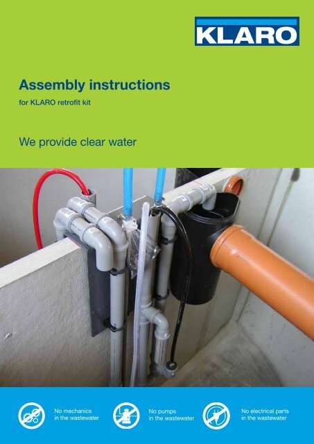
<strong>Assembly</strong> <strong>instructions</strong>for <strong>KLARO</strong> retrofit kitWe provide clear waterNo mechanicsin the wastewaterNo pumpsin the wastewaterNo electrical partsin the wastewater
<strong>Assembly</strong> <strong>instructions</strong> for <strong>KLARO</strong> retrofit kitsIMPORTANT: All safety <strong>instructions</strong> must be observed! Keep for future reference.1. Product description .......................................................................................................... 31.1. Field of application .......................................................................................................... 31.2. Transport ......................................................................................................................... 31.3. Inspection of the delivery / scope of delivery .................................................................. 31.4. Storage ........................................................................................................................... 32. Preparation of the wastewater pit ................................................................................... 42.1. Work in the pit ................................................................................................................. 42.2. Empty conduit ................................................................................................................. 42.3. Ventilation of the plant .................................................................................................... 53. Installation of the Klaro Quick retrofit kit ....................................................................... 53.1. <strong>Assembly</strong> of the aeration unit .......................................................................................... 53.2. Attaching the submerged foil........................................................................................... 53.3. Installation into the pit ..................................................................................................... 54. Installation of the <strong>KLARO</strong> Disc retrofit kit ...................................................................... 94.1. <strong>Assembly</strong> of the aeration unit .......................................................................................... 94.2. <strong>Assembly</strong> of the lifts and integrated sampling unit ........................................................ 104.2.1. Charging lift (red) ........................................................................................................ 104.2.2. Excess sludge lift (white) ............................................................................................ 104.2.3. Sampling unit .............................................................................................................. 104.2.4. Discharging lift (black) ................................................................................................ 104.3. <strong>Assembly</strong> for full-circle plants ........................................................................................ 114.4. Air hoses ....................................................................................................................... 145. <strong>Assembly</strong> of the switch cabinet .................................................................................... 156. Commissioning of the plant .......................................................................................... 152 <strong>KLARO</strong> <strong>GmbH</strong>
<strong>Assembly</strong> <strong>instructions</strong> for <strong>KLARO</strong> retrofit kits1. Product description1.1. Field of applicationThe retrofit kit consists of a machine cabinet and the installation parts for the existing pit. It isused e.g. retrofitting an existing multiple-chamber to a fully biological wastewater treatmentplant. The assembly and installation <strong>instructions</strong> of the cabinet must also be followed.1.2. TransportThe retrofit kits are delivered in cardboard packaging. Where necessary, information abouthandling the packaged products is provided on the cardboard boxes (See example providedin Figure 1). In order to avoid any damage, this information must be observed both fortransport and for storage! Proven non-compliance will result in any warranty claims beingdeclared void.Figure 1: Information on the packaging1.3. Inspection of the delivery / scope of deliveryOn the basis of the delivery note, all parts must be checked for completeness and for anydamage in transit immediately after delivery. We will not accept any complaints that aresubmitted at a later time. Damaged parts must not be installed.In general, the supplied retrofit kit consists of the following components: 1 charging lift, DN 50 / 70, made of HT, marked in red; 1 clearwater lift, DN 50 / 70, made of HT, marked in black; 1 or more excess sludge lift(s), DN 50, made of HT, marked in white; Aeration unit(s) with piping made of stainless steel with diaphragm pipes or discsmade of EPDM, with fine perforation; Accessories box with assembly materials for lifts and ventilation unit(s); Submerged foil; Sampling unit (optional); Air hoses (optional); UV module (optional); Switch cabinet with Klaro control unit.1.4. StorageThe place of storage should be dry and protected against harmful environmental influences(e.g. UV light) and external influences.<strong>KLARO</strong> <strong>GmbH</strong> 3
<strong>Assembly</strong> <strong>instructions</strong> for <strong>KLARO</strong> retrofit kits2. Preparation of the wastewater pit2.1. Work in the pitThe plant must be stable and durable. Any holes and/or slots in the dividing walls and outerwalls must be sealed permanently. Due to its harmfulness to the environment, bitumenmust not be used for sealing the plant. The entire plant must be completely tight both inorder to prevent water from entering and wastewater from leaking through the walls and inorder to prevent wastewater from passing through the dividing walls in an uncontrolledmanner. The effectiveness of the sealing measures taken must be verified and documentedin accordance with DIN 4261-1.The preparatory work in the wastewater pit is very important for permanent and safeoperation of the plant. Please be particularly careful when following these assembly<strong>instructions</strong>.Two-chamber pitThree-chamber pitFigure 2: Two-chamber pitExcept for an emergency overflow, alltransitions between the 1 st and the 2 ndchamber must be sealed above the highestwater level.Figure 3: Three-chamber pitAbove the highest water level, an emergencyoverflow must be provided in the dividing wallbetween the 1 st and the 2 nd chamber.The transitions between the 2 nd and 3 rd chambermust be designed as submerged openings. Theymust be of a size between DN 150 and DN 200.The upper edge of the openings must be at least300 mm below the water surface; the bottomedge must not reach down by more than half thewater depth.Figure 4: Emergency overflow in dividing wall2.2. Empty conduitAn empty conduit DN 150 with an inside pull wire and a gradient must be installed from theplace of installation of the technical equipment cabinet to the tank of the wastewater4 <strong>KLARO</strong> <strong>GmbH</strong>
<strong>Assembly</strong> <strong>instructions</strong> for <strong>KLARO</strong> retrofit kitstreatment plant. If a wall penetration DN 100 is used for the transition into the building, areducer DN 150/100 must be mounted at the end of the empty conduit. To the greatestextent possible, the empty conduit must be installed in a straight manner. The requiredcurves must be formed by means of moulded bodies of an angle of not more than 30°. Thelength of the empty conduit must not exceed 20 m. For longer distances, please contact us.The empty conduit must be sealed gas-tight at the switch cabinet (See installation<strong>instructions</strong> for the cabinet).2.3. Ventilation of the plantAccording to DIN 4261-1, all chambers / tanks must be ventilated. If required, additionalventilation lines or ventilation openings must be installed. The ventilation lines must beinstalled in such a manner that natural ventilation is possible (chimney effect). Werecommend verifying the ventilation by means of a smoke bomb on the dividing wall.3. Installation of the Klaro Quick retrofit kit3.1. <strong>Assembly</strong> of the aeration unitPlease remove the <strong>KLARO</strong> retrofit kit from its packaging and screw the two short stainlesssteel pipes (length of 35 cm) onto the stainless steel angles of 90° at the ends of thedownpipes. Then, the two disc aerators must be carefully tightened manually into theprovided threads. Please note that Teflon tape must be wrapped around all threads.DownpipeSeal all threads withTeflon tape!Membrane discsDiaphragm discsManually tightenthe plastic threadsFigure 5: Installation of the <strong>KLARO</strong> ventilation unitCare must be taken that no water enters the disc aerators before or during anyassembly work.3.2. Attaching the submerged foilThe emergency overflow in the dividing wall (Figure 4) must be protected against theoverflow of floating sludge from the primary settlement chamber into the environment. To thisend, the supplied submerged foil in the primary settlement chamber must be dowelled to thedividing wall. Here, the foil should be flush with the upper edge of the dividing wall andaligned in such a manner that the curved part covers the emergency overflow completely(see Figure 11, page 8).3.3. Installation into the pitThe fully assembled Klaro Quick retrofit kit is placed on the centre of the dividing wall andcan be attached onto the centre of the dividing wall by means of an anchor bolt (see<strong>KLARO</strong> <strong>GmbH</strong> 5
<strong>Assembly</strong> <strong>instructions</strong> for <strong>KLARO</strong> retrofit kitsFigure 12). The stainless steel downpipes must be pushed downwards until the curves reston the ground. Care must be taken that the diaphragm discs are aligned horizontally. Whereapplicable, the discs must be readjusted accordingly by rotating the horizontal pipe. Theoutlet lift must be aligned and fixed in such a manner that safe delivery into the outlet of theplant is ensured and that the lift cannot get out of place. Afterwards, the air hoses can beconnected.Figure 6: <strong>KLARO</strong> Quick ZK with 1 membrane disc,assembled in the two-chamber pitFigure 7: <strong>KLARO</strong> Quick ZK with 2 membrane discs,assembled in the two-chamber pit6 <strong>KLARO</strong> <strong>GmbH</strong>
<strong>Assembly</strong> <strong>instructions</strong> for <strong>KLARO</strong> retrofit kitsFigure 8: <strong>KLARO</strong> Quick ZK with 1 membrane disc,assembled in the three-chamber pitFigure 9: <strong>KLARO</strong> Quick DK, assembled in the threechamberpitFeedOutletFeed1Key1 Submerged opening2 Emergency overflow with scum board3 Feed lift4 Diaphragm disc aerator5 Borehole for percussion dowel for fixation6 Excess sludge lift7 Outlet lift at the sampling unit64513274OutletFigure 10: <strong>KLARO</strong> Quick DK, assembled in a three-chamber pit<strong>KLARO</strong> <strong>GmbH</strong> 7
<strong>Assembly</strong> <strong>instructions</strong> for <strong>KLARO</strong> retrofit kitsEmergency overfillScum boardCharging lifterFigure 11: <strong>KLARO</strong> Quick for two-chamber tanks – 1 chamberDowel for fixationExcess sludge lifterClear water lifterFigure 12: <strong>KLARO</strong> Quick for two-chamber tanks -2 chambers8 <strong>KLARO</strong> <strong>GmbH</strong>
<strong>Assembly</strong> <strong>instructions</strong> for <strong>KLARO</strong> retrofit kitsClear water lifterExcess sludge lifterSampling pointCharging lifterDowel for fixationFigure 13: <strong>KLARO</strong> Quick for three-chamber tanks – 2 and 3 chambers4. Installation of the <strong>KLARO</strong> Disc retrofit kitFor the Klaro Disc retrofit kit, each component must be attached separately in the tank.4.1. <strong>Assembly</strong> of the aeration unitFigure 14: Tank with two chambers: aeration in a semicircleat a diameter of 2.5 mFigure 15: Tank with three chambers: aeration in twoquadrants<strong>KLARO</strong> <strong>GmbH</strong> 9
<strong>Assembly</strong> <strong>instructions</strong> for <strong>KLARO</strong> retrofit kits1. Inlet2. Outlet3. Sludge storage + buffer4. Charging lifter5. Scum board6. Membrane disc aerator7. Clearwater lifter at the integrated samplingpoint8. Excess sludge lifter, SB reactorThe membrane disc aerators must be aligned exactly vertically above the tank bottom. Eachdownpipe must be attached to the concrete wall by means of two pipe clamps.4.2. <strong>Assembly</strong> of the lifts and integrated sampling unit4.2.1. Charging lift (red)The feed lift is attached by means of three (DN 50) and/or four (DN 70) pipe clamps whichmust be dowelled to the dividing wall of the tank. If the dividing wall of the tank is 20 cmhigher than the bottom of the outlet, the lift can be placed on the dividing wall. In case ofdeviations, such deviations must be taken into account when carrying out the assembly work.The lift outlet must reach into die SBR chamber.4.2.2. Excess sludge lift (white)In the SBR chamber, the excess sludge lift must be installed in the corner of the tank outlet.Fix the lift by means of two pipe clamps. The horizontal piece should be placed on the wall ofthe tank. The suction lift of the lift has deliberately been chosen to be at some distance fromthe bottom of the tank in order to limit the pumping of activated sludge.4.2.3. Sampling unitIn order to assemble the integrated sampling unit, the outlet pipe is extended to such extenttowards the dividing wall until the sampling unit that has been put onto the outlet pipe can beattached to the dividing wall by means of a dowel.4.2.4. Discharging lift (black)The discharging lift is attached by means of three (DN 50) and/or four (DN 70) pipe clampswhich must be dowelled to the dividing wall of the tank. If the dividing wall of the tank is20 cm higher than the bottom of the outlet, the upper horizontal pipe of the lift should be atthe same height of the upper edge of the dividing wall. In case of deviations, such deviationsmust be taken into account when carrying out the assembly work. The lift outlet must reachinto the integrated sampling unit.10 <strong>KLARO</strong> <strong>GmbH</strong>
<strong>Assembly</strong> <strong>instructions</strong> for <strong>KLARO</strong> retrofit kitsFigure 16: Inlet lift DN 50 with scum board andemergency overflowFigure 17: Excess sludge lift DN 50, clearwater liftDN 50 and integrated sampling unit with emergencyoverflow4.3. <strong>Assembly</strong> for full-circle plantsFigure 18: Plant with full-circle aeration unit for diameters of 2.0 m and 2.5 mIn order to assemble the full-circle aeration unit, a stainless steel downpipe is required foreach SBR tank. Starting from a water depth of 1.5 m, a horizontal traverse (Figure 26) mustbe assembled in the tank in order to stabilise the downpipe.At the foot of the downpipe, the line is divided by means of a T-piece.The distribution to the discs is carried out in accordance with Figure 19 and Figure 20.<strong>KLARO</strong> <strong>GmbH</strong> 11
<strong>Assembly</strong> <strong>instructions</strong> for <strong>KLARO</strong> retrofit kitsFigure 19: Piping for the aeration unit with 3 discsFigure 20: Piping for the aeration unit with 4 discsAfter the aeration unit has been placed in the tank, the supplied concrete weight is threadedvia the vertical downpipe for vertical fixation and lowered to the bottom.Figure 21: Tank diameter of 2 mFigure 22: Tank diameter of 2.5 mImportant information about the anchor bolt assembly:1. Make a borehole.2. Clean the borehole.3. Drive the bolt into concrete up until the seat depthmark.4. After the nut has been tightened, screw on the pipeclamp.12 <strong>KLARO</strong> <strong>GmbH</strong>
<strong>Assembly</strong> <strong>instructions</strong> for <strong>KLARO</strong> retrofit kitsTraverse2x Stainless steel pipe clamp1x Threaded rod1x Stainless steel pipe clamp1x Hexagonal bolt1x Nut2x PE pipe clampfitted into each otherDN 50DN 70DN 50DN 701x PE pipe clamp1x Stainless steel pipe clamp1x Hexagonal bolt1x PE pipe clamp1x Stainless steel pipe clamp1x Threaded rod2x Stainless steel pipe clamp1x Threaded rodFigure 23: Attaching the clearwater lift (DN50 or DN70) to the stainless steel downpipeFasten the lift by means ofthe drilling screw1x Stainless steel pipeclamp1x Anchor boltFigure 24: Attaching the inlet lift (DN50 3 pipeclamps, DN70 4 pipe clamps)Figure 25: Attaching the excess sludge lift<strong>KLARO</strong> <strong>GmbH</strong> 13
<strong>Assembly</strong> <strong>instructions</strong> for <strong>KLARO</strong> retrofit kitsFigure 26: Attaching the downpipe and the integrated sampling unit to the horizontal traverse by means of astainless steel clamp4.4. Air hosesAir hoses are required to establish a connection between the concrete tank and the machinecabinet. These hoses must be ordered separately in the respectively required length. In orderto avoid mixing up the hoses when connecting them, we deliver the hoses in different colours– according to the colour codes used for the lifts in the tank.Valve Component Colour1 Charging red2 Aeration blue3 Discharging black4 Excess sludge lift whiteAs a matter of principle, the air hoses must be attached in such a manner that they can beprevented from kinking. The hose must be either secured by means of a pipe clamp attachedto the cone (Figure 27) or fixed to the downpipe by means of a cable tie in a smooth curve(Figure 28).14 <strong>KLARO</strong> <strong>GmbH</strong>
<strong>Assembly</strong> <strong>instructions</strong> for <strong>KLARO</strong> retrofit kitsFigure 27: Attaching the air hose to the cone by meansof cable tiesFigure 28: Attaching the air hose to the downpipe in asmooth curveAfterwards, the four air hoses must be pulled through the empty conduit by means of a pullwire. Particular care must be taken that the air hoses are not kinked.<strong>Assembly</strong> of the air barrier at the discharging air liftWhen integrating the hose for the airbarrier by means of a T-connector intothe air line of the excess sludge lifter, itmust always be ensured that any kinkingof the hoses during operation can beexcluded.The T-connector should be positionedabove the waterline.Connection with the air lineof the excess sludge lifterInlet connectorwith air lockClearwater lifterExcess sludge5. <strong>Assembly</strong> of the switch cabinetThe product description and technical data about your switch cabinet can be found in theassembly and commissioning <strong>instructions</strong> supplied with the switch cabinet.6. Commissioning of the plantAfter the installation of the Klaro retrofit kit, the connection of the air hoses in the pit and theassembly of the switch cabinet, the entire plant must be filled with fresh water. Only then maythe plant be commissioned. Information about the commissioning can be found in theassembly and commissioning <strong>instructions</strong> supplied with the switch cabinet.Version: 04/2013Subject to technical changes!<strong>KLARO</strong> <strong>GmbH</strong> 15
<strong>KLARO</strong> <strong>GmbH</strong>Spitzwegstraße 6395447 BayreuthTelephone: +49 (0) 921 16279-0Fax: +49 (0) 921 16279-100E-Mail: info@klaro.euMore information atwww.klaro.euTechnical hotline+49 (0) 921 16279-330Photo copyright: <strong>KLARO</strong> <strong>GmbH</strong> © <strong>KLARO</strong> <strong>GmbH</strong> Bayreuth 2013 / Art.-No. KKA 0084-02-2013


