Turbomachinery for the world's largest nitrogen plant - MAN Diesel ...
Turbomachinery for the world's largest nitrogen plant - MAN Diesel ...
Turbomachinery for the world's largest nitrogen plant - MAN Diesel ...
- No tags were found...

Create successful ePaper yourself
Turn your PDF publications into a flip-book with our unique Google optimized e-Paper software.
<strong>Turbomachinery</strong> <strong>for</strong> <strong>the</strong> world’s<strong>largest</strong> <strong>nitrogen</strong> <strong>plant</strong>Enhanced Oil Recovery to increase <strong>the</strong> outputin <strong>the</strong> Cantarell oil field, Mexico
<strong>Turbomachinery</strong> <strong>for</strong> <strong>the</strong>world’s <strong>largest</strong> <strong>nitrogen</strong> <strong>plant</strong>Enhanced Oil Recovery toincrease <strong>the</strong> output in <strong>the</strong>Cantarell oil field, MexicoDr.-Ing. L. Turanskyj<strong>MAN</strong> Turbomaschinen AGGHH BORSIGOberhausen, GermanyB.A. Keenan BSc C.Eng. FIMechEBOC Process Gas Solutions,Guild<strong>for</strong>d, Surrey, EnglandPaper presented at <strong>the</strong>“Exposición Latinoamericana delPetróleo” Maracaibo, Venezuela,26-28 June 2001SummaryAs part of a project to increase<strong>the</strong> production output of PEMEX’sCantarell offshore oil field, situatedin <strong>the</strong> Gulf of Mexico, <strong>the</strong> world’s<strong>largest</strong> ever <strong>nitrogen</strong> <strong>plant</strong> has beenconstructed. It was designed, built,owned and operated by Companiade Nitrogeno de Cantarell S.A. deC.V. (CNC) an international consortiumof BOC Gases of Great Britain,Westcoast Energy of Canada,Marubeni of Japan, Linde Germanyand ICA Fluor Daniel of Mexico.For this project, <strong>MAN</strong> TurbomaschinenAG GHH BORSIG was awarded<strong>the</strong> order to supply, supervise <strong>the</strong>erection of and commission <strong>the</strong> aircompressors <strong>for</strong> <strong>the</strong> air separation<strong>plant</strong> and <strong>the</strong> <strong>nitrogen</strong> productcompressors including <strong>the</strong>ir drivers<strong>for</strong> <strong>the</strong> delivery of <strong>the</strong> high purity<strong>nitrogen</strong> to <strong>the</strong> oil field. The totalinstalled driver power <strong>for</strong> compressionexceeds 400 MW.This paper contains a brief descriptionof <strong>the</strong> <strong>plant</strong> as a whole, detailsof <strong>the</strong> turbomachines supplied and<strong>the</strong> results of <strong>the</strong>ir workshop trials.IntroductionMethods of introducing <strong>nitrogen</strong>under high pressure into oil fieldswith a low well pressure or to increaseproduction can be used<strong>for</strong> enhanced oil recovery ei<strong>the</strong>r if<strong>the</strong>re is insufficient gas available <strong>for</strong>reinjection, or <strong>the</strong> associated gasis to be used <strong>for</strong> ano<strong>the</strong>r purpose.Petroleos Mexicanos (PEMEX),<strong>the</strong> Mexican state oil company, isutilizing <strong>the</strong>se methods to increaseits future production capacity in <strong>the</strong>Cantarell oil field.2
PEMEX’s production output to datefrom its main oil field accounts <strong>for</strong> athird of total domestic oil production.The Cantarell oil field is located offshorein <strong>the</strong> Bay of Campeche, in<strong>the</strong> sou<strong>the</strong>rn Gulf of Mexico (Fig. 1).Roughly 1.4 million barrels per dayof crude oil have been producedhere on average in previous years.In addition to o<strong>the</strong>r measures toincrease <strong>the</strong> daily output to around2 million barrels per day, <strong>the</strong> diminishingwell pressure of <strong>the</strong> crude oilis to be increased to approx. 84 barand maintained at that level byinjecting highly pure <strong>nitrogen</strong> into<strong>the</strong> rock <strong>for</strong>mations containing <strong>the</strong>oil. To do this, around 1.3 millionNm 3 /h or roughly 40,300 tonnes perday of <strong>nitrogen</strong> are required, whichare produced from atmosphericair in an air separation <strong>plant</strong> andfollowing compression in turbocompressorsto 121 bar is transportedto <strong>the</strong> offshore injection facilities ina 36” subsea pipeline approx.92 km long.source: www.enr.comFig. 1: Location of <strong>the</strong> Cantarell Oil FieldThe scope of <strong>the</strong> project won comprises,as shown in Fig.2, a naturalgas fired gas turbine COGEN power<strong>plant</strong>, an air separation <strong>plant</strong> toproduce <strong>the</strong> <strong>nitrogen</strong>, seawater andtreated water cooling systemsincluding <strong>the</strong> subsea water pipes,turbocompressor sets and pipelinesto <strong>the</strong> plat<strong>for</strong>m. It was constructedon <strong>the</strong> Atasta peninsula on <strong>the</strong> Gulfof Mexico, not far from Cuidad delCarmen, by CNC, an internationalconsortium made up of <strong>the</strong> followingcompanies:BOC Gases/Great BritainMarubeni Corporation/JapanWestcoast Energy Inc./CanadaLinde AG/GermanyICA Fluor Daniel S.de R.L. de C.V./Mexico.The last-named company is a jointventure between Constructoras ICA(Mexico) and Fluor Daniel (USA).At <strong>the</strong> end of 1997, ICA Fluor Daniel,in consultation with BOC, awarded<strong>the</strong> contract to supply <strong>the</strong> turbocompressorsets on ei<strong>the</strong>r side of <strong>the</strong> airseparation <strong>plant</strong> to <strong>MAN</strong> TurbomaschinenAG GHH BORSIG, whichwas also contracted to superviseerection of <strong>the</strong> compressors and tocommission <strong>the</strong>m.Fig 2: Plant Schematic3
Plant conceptsource: Fluor DanielPemex awarded <strong>the</strong> CNC consortium,led by BOC, a gas supply contract<strong>for</strong> a period of 15 years. This decisionwas based on <strong>the</strong> lowest gas pricecoupled with design, constructionand operating experience. Key tothis award was experience of <strong>the</strong>components including <strong>the</strong> machinery,minimum fuel consumption measuredin energy units per unit capacityof <strong>nitrogen</strong>,and a predicted highlevel of availability of <strong>the</strong> <strong>plant</strong>.The facility was built on a green fieldsite provided by Pemex. There wasno infrastructure or utilities, with <strong>the</strong>exception of natural gas which isused to fuel <strong>the</strong> gas turbines. Owingto this lack of infrastructure at <strong>the</strong>erection site, <strong>the</strong> <strong>plant</strong> in its entirety,including <strong>the</strong> gas turbine cogeneration<strong>plant</strong>, was designed as anisland solution.Fig. 3: Nitrogen Production PlantIn designing <strong>the</strong> <strong>plant</strong>, it was recognisedthat minimum energy usagecombined with <strong>the</strong> best economicsolution could only be accomplishedby a high level of integration whichwould balance <strong>the</strong> optimum airseparation cycle with <strong>the</strong> optimumenergy supply cycle. As BOC hadexperience successfully designing,building and operating such facilitiese.g. <strong>the</strong>ir integrated gas turbinecogeneration and ASU facility atGresik Indonesia, ano<strong>the</strong>r facilityusing <strong>MAN</strong> GHH BORSIG’s compressorsand steam turbines, BOCled this activity. Using proprietarycomputer programs, in excess of40 combined energy and ASUcycles were evaluated includingvariation of process cycles, variationsof compressor types and coolingarrangements, simple cycle, combinedcycle, and cogeneration gasturbine arrangements be<strong>for</strong>e <strong>the</strong>optimum solution was decided on anNPV and experience basis. The solutioneventually implemented as <strong>the</strong>most economical is based on a fourASU-train version as follows:– Four (three operating/one spare)gas turbine generators with heatrecovery steam generators (HRSGs)connected downstream to <strong>the</strong> gasturbine exhausts to generate steam– four motor driven intercooled aircompressors,– four air separation <strong>plant</strong>s toproduce <strong>the</strong> <strong>nitrogen</strong> and– four steam turbine driven intercooled<strong>nitrogen</strong> compressors.Splitting <strong>the</strong> total production betweenfour units that can be operated independentlyalso provides <strong>the</strong> requiredflexibility of <strong>the</strong> <strong>nitrogen</strong> <strong>plant</strong> in <strong>the</strong>event that <strong>the</strong> oil field requirementsvary.Fig. 3 shows a photograph of <strong>the</strong><strong>nitrogen</strong> production <strong>plant</strong>. The fourgas turbine units – gas turbines,generators and HRSGs – are on <strong>the</strong>left hand side of <strong>the</strong> picture. Themachine house can be seen opposite<strong>the</strong>se, in <strong>the</strong> middle of <strong>the</strong>picture. The four turbocompressorsets – four air compressors withmotor drive and <strong>the</strong> four <strong>nitrogen</strong>compressor sets with condensingsteam turbines, gear units and lowandhigh-pressure <strong>nitrogen</strong> compressors– are housed here. At <strong>the</strong>right-hand side of <strong>the</strong> picture are <strong>the</strong>four air separation facilities, and <strong>the</strong>sea water recooling system withcooling towers in all is located in<strong>the</strong> left-hand section. The area asa whole is roughly 6 km from <strong>the</strong>coast. Water is piped from 5 kmoffshore of a sump at <strong>the</strong> beachwhere it is pumped to <strong>the</strong> coolingtowers <strong>for</strong> use in <strong>the</strong> intercoolersand condensers.4
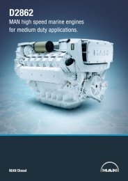
<strong>Turbomachinery</strong><strong>MAN</strong> Turbomaschinen AG GHHBORSIG supplied <strong>the</strong> following 16turbomachines <strong>for</strong> <strong>the</strong> <strong>nitrogen</strong> <strong>plant</strong>:Four intercooled axial flow air compressorsconsisting of two back toback axial stage groups and oneoverhung radial stage driven by ABBtwo pole synchronous motors, andfour intercooled centrifugal <strong>nitrogen</strong>compressor trains. Each <strong>nitrogen</strong>compressor train consists of a lowpressure casing driven by a condensingsteam turbine through a stepup gearbox with each low pressurecasing directly connected to a highpressure casing. The following is amore detailed description of <strong>the</strong>seturbomachines:Axial flow main aircompressors<strong>MAN</strong> GHH BORSIG is <strong>the</strong> marketleader in <strong>the</strong> construction of axialcompressors <strong>for</strong> industrial applications.Axial compressors were developedat <strong>the</strong> start of <strong>the</strong> 1950s andFig. 5: Axial Flow Compressor Arrangementhave since been introduced verysuccessfully into various market segmentsof <strong>the</strong> process industry. While<strong>the</strong>ir primary use initially was in blastfurnace applications, <strong>the</strong> emphasishas shifted over time increasingly to<strong>the</strong> chemical and petrochemicalsector, and also to <strong>the</strong> “air separation<strong>plant</strong>” segment of <strong>the</strong> market.Thus since 1977 <strong>MAN</strong> GHH BORSIGhas supplied a total of 14 identicalaxial flow compressors, each with36 MW (48275 HP) drive power, to<strong>the</strong> world’s <strong>largest</strong> oxygen <strong>plant</strong> inSasolburg, South Africa. Thesecompressors have now successfullyclocked up around 2 million operatinghours. The compressor design isdescribed in detail in [1].The axial flow compressors used <strong>for</strong><strong>the</strong> air separation <strong>plant</strong> on Atastaare virtually identical to those <strong>for</strong> <strong>the</strong>Sasolburg installation. Each of <strong>the</strong>four machines operates at over50 MW (67050 HP) with suctionvolumes in excess of 600,000 m 3 /h(353100 acfm) depending on <strong>plant</strong>demand and ambient conditions.The power required is supplied by asynchronous motor directly driving <strong>the</strong>compressor at 3,600 rpm and startedby a soft starter. Its rated drive outputis 52 MW (69733 HP).The air is taken in via a radial inletcasing (Fig. 4) and following compressionin seven axial stages and afinal radial end stage in <strong>the</strong> low-pressuresection, is conveyed to <strong>the</strong> intercoolerlocated beneath <strong>the</strong> compressor(Fig. 5). Following fur<strong>the</strong>r compressionin <strong>the</strong> intermediate-pressuresection (six axial stages and radialend stage) and fur<strong>the</strong>r stage of intercooling,final compression is carriedout in <strong>the</strong> overhung-mounted radialstage with axial intake.Fig. 4: Intercooled Axial Flow Compressor5
Fig. 6: Nitrogen LP CompressorFig. 7: Nitrogen HP CompressorFig. 8: Condensing Steam TurbineThe wide range of compressorper<strong>for</strong>mance data required can bedelivered with just four synchronouslyadjustable rows of stator bladesat <strong>the</strong> inlet to <strong>the</strong> low-pressuresection. The reasons <strong>for</strong> <strong>the</strong> superbpartial load characteristics lie in <strong>the</strong>moderate aerodynamic loading of<strong>the</strong> blading of <strong>the</strong> low- and intermediate-pressuresection toge<strong>the</strong>rwith <strong>the</strong> stage characteristics of <strong>the</strong>HP stage.The dimensions of <strong>the</strong> axial flowcompressor can best be characterizedby <strong>the</strong> distance betweenbearings of around 6 m, <strong>the</strong> outerdiameter of <strong>the</strong> <strong>largest</strong> centrifugalimpeller of 1.64 m and <strong>the</strong> transportationweight of roughly 180 tonnes.Centrifugal type <strong>nitrogen</strong>product compressorsEach of <strong>the</strong> four centrifugal compressortrains designed to API Standardoperates at up to 48 MW dependingon <strong>the</strong> well demand profile and compressesin excess of 335,000 Nm 3 /h(300 million standard cubic feet perday) at pressures up to 121 bara(1755 psia).The low-pressure compressor, twotimes intercooled, contains four impellerswith a nominal outer diameterof 750 mm (Fig.6). The two externalvolutes with a circular cross-sectionare typical of <strong>the</strong> cast casing with ahorizontal split joint and are connectedto <strong>the</strong> vaneless diffusers of <strong>the</strong>respective stages.The high-pressure compressor isprovided with two stages of intercooling(Fig.7) and contains threestage groups, each comprising twoimpellers with an outer diameter of660 mm. The casing of cast steel isdesigned as a barrel with a singlecover. On this compressor also,volutes with a circular cross-sectionand a connected conical diffuseroptimize efficiency in transferring <strong>the</strong>compressed <strong>nitrogen</strong> to <strong>the</strong> coolerslocated beneath <strong>the</strong> machine. Theinitial stages of <strong>the</strong> three HP stagegroups have vaned diffusers. The HPcompressors are constructed withoutan internal casing; in place ofthis, <strong>the</strong> internals are connected viaspecial tie-bolts to <strong>for</strong>m <strong>the</strong> axiallyremovable barrel.Both compressors have single drygas seals at <strong>the</strong> shaft ends to seal<strong>the</strong> gas chambers relative to atmosphere.To achieve optimum efficiency of <strong>the</strong>selected compressor configuration,<strong>the</strong> flow-conducting componentswere produced with a particularlyhigh-grade surface finish, especiallyon <strong>the</strong> HP compressor.Because of <strong>the</strong> power required by<strong>the</strong> compressors, <strong>the</strong>ir rotor lengthsand, <strong>for</strong> <strong>the</strong> <strong>nitrogen</strong> compressor, <strong>the</strong>pressure at which it worked, specialattention was paid to <strong>the</strong> rotordynamics.The design was carried out inaccordance to API 617 includingboth unbalance response analysisand log decrement analysis to confirmstability.Steam turbinesEach of <strong>the</strong> steam turbine drivers<strong>for</strong> <strong>the</strong> <strong>nitrogen</strong> compressors obtain<strong>the</strong>ir steam from waste heat boilersconnected to each of <strong>the</strong> gas turbines.Each steam turbine can expandmore than 160 t/h of high pressure/high temperature steam to produce upto 55 MW (73755 HP) at 3,200 rpm.6
Fig.8 shows a section through atypical, reaction-type condensingsteam turbine <strong>for</strong> mechanical drives.With an isentropic efficiency rating ofalmost 85%, this turbomachine alsomeets <strong>the</strong> high standards expectedwith regard to optimum energy utilizationby <strong>the</strong> overall <strong>plant</strong>.The 23-stage turbine blading is dividedinto four sections. The rotor bladesof <strong>the</strong> two-stage control wheel, <strong>the</strong>HP and IP part and <strong>the</strong> first threestages of <strong>the</strong> LP part have integratedshrouds, into which damping wiresare caulked in a circumferential direction.Only <strong>the</strong> last four rotor bladesof <strong>the</strong> LP part are free-standing. Allblades up to <strong>the</strong> end stage are heldin <strong>the</strong> rotor by T roots or double-Troots. The end stage has a fingerroot fixing which is attached to <strong>the</strong>rotor by two pins. The guide vanesare connected in segments on <strong>the</strong>rotor side to riveted shrouds, againstwhich sealing strips caulked into <strong>the</strong>shaft run.Four control valves are used <strong>for</strong>partial load control. These are connectedto one ano<strong>the</strong>r by a balancebeam control system, which is actuatedby hydraulic oil. The controlFig. 9: Nitrogen CompressorTrain Arrangementvalves are coordinated so that avirtually linear connection is createdbetween <strong>the</strong> steam throughput andvalve stroke.Special features of <strong>the</strong> steam turbinedesign include <strong>the</strong> welded jointbetween <strong>the</strong> cast turbine casingand welded exhaust casing, and <strong>the</strong>bearing housings set up separatelyto <strong>the</strong> turbine casing. The first of<strong>the</strong>se features contributes substantiallyto <strong>the</strong> tightness of <strong>the</strong> horizontalsplit joint, even when <strong>the</strong> turbineis started up and stopped frequently;<strong>the</strong> second facilitates simple alignmentof <strong>the</strong> casing and rotor, whichis retained even during transientoperating conditions.The <strong>nitrogen</strong> compressor trainarrangement is shown in Fig.9.Plant dynamicsand controlThe definition of <strong>plant</strong> dynamicshere means <strong>the</strong> analysis of transientoperating states of turbomachineryinstallations such as occur duringstart-up and shutdown, in controlprocesses and in <strong>the</strong> event ofsystem malfunction. <strong>MAN</strong> GHHBORSIG began at an early stageto analyse <strong>the</strong> behaviour of turbomachinerysystems under a<strong>for</strong>ementionedoperating conditions [2], [3].One aim of <strong>the</strong>se investigations is toensure a mode of operation <strong>for</strong> compressorinstallations that excludesunstable events such as “surging”even <strong>for</strong> transient operating states.In dynamic simulation, <strong>the</strong> <strong>the</strong>rmodynamicattributes of <strong>the</strong> compressorsin <strong>the</strong> <strong>for</strong>m of per<strong>for</strong>mancedata, <strong>the</strong> characteristics of <strong>the</strong> driveunits, <strong>the</strong> mass moments of inertiaof all rotating components, <strong>the</strong> storagevolumes of <strong>the</strong> gas coolers and<strong>the</strong> gas-carrying pipelines, plus <strong>the</strong>attributes of <strong>the</strong> controllers used,and <strong>the</strong> corresponding valves andfittings as related to one ano<strong>the</strong>r bymeans of a system of differentialequations, which are solved digitally.As a result of this simulation, all <strong>the</strong>important time-dependent parameters,such as speeds, pressures,volume flows etc. in <strong>the</strong> transientbehaviour of <strong>the</strong> installation areavailable <strong>for</strong> fur<strong>the</strong>r evaluation. Byvarying elements of <strong>the</strong> <strong>plant</strong>, e.g.<strong>the</strong> arrangement and attributes ofvalves and fittings, this behaviour canbe influenced in a targeted mannereven at <strong>the</strong> <strong>plant</strong> design stage.7
of mechanical and <strong>the</strong>rmodynamictrials are precisely stipulated invarious internationally approved acceptancecodes <strong>for</strong> <strong>the</strong> respectivemachine types. Customers andthose <strong>the</strong>y commission to carry outacceptance <strong>the</strong>re<strong>for</strong>e devote particularattention to <strong>the</strong>se test runs.Fig. 10: Nitrogen Compressor LoopOne example of using this simulationsystem is shown in Fig. 10, showing<strong>the</strong> system design of <strong>the</strong> <strong>nitrogen</strong>compressors. To avoid “surging” ofindividual stages or stage groups intransient processes, recycle valvesare provided <strong>for</strong> certain stagegroups, which open automaticallywhen required. Fig.11 shows as <strong>the</strong>result of such simulation how <strong>the</strong>transient effects of a shutdown process– in this case by means of turbinetripping – can be traced in <strong>the</strong>per<strong>for</strong>mance map of <strong>the</strong> 6th stagegroup of <strong>the</strong> <strong>nitrogen</strong> compressor set.The turbomachinery and relatedunits are controlled and monitoredby <strong>the</strong> proven turbolog DSP machinecontrol and protection system, whichwas developed in-house. Linked to<strong>the</strong> digital control and monitoringsystem of <strong>the</strong> overall <strong>plant</strong>,turbolog DSP protects <strong>the</strong> air and<strong>nitrogen</strong> compressors against surging,controls <strong>the</strong> position of <strong>the</strong>variable stator vanes of <strong>the</strong> axialflow compressors, <strong>the</strong> speed of <strong>the</strong>steam turbines, monitors and controlsall <strong>the</strong> o<strong>the</strong>r components, andlast but not least handles <strong>the</strong> visualizationof <strong>the</strong> operating data required<strong>for</strong> smooth, uninterrupted production.Workshop trialsWorkshop trials of <strong>the</strong> compressorsand <strong>the</strong>ir drivers serve to demonstrate<strong>the</strong> guaranteed mechanicalintegrity of <strong>the</strong> finished product aswell as <strong>the</strong> guaranteed <strong>the</strong>rmodynamicproperties prior to dispatch to<strong>the</strong> site as it has long been recognisedthat it is easier and more costeffective to fix a problem in <strong>the</strong> factoryra<strong>the</strong>r than in <strong>the</strong> field. For suchlarge units <strong>the</strong> cost of one weeksdelay can result in over $1 million inlost revenue. These test runs areto be regarded as a comprehensivequality assurance measure at <strong>the</strong>end of <strong>the</strong> design and manufacturingprocess. The procedure and contentFig. 11: Result of Dynamic Simulation<strong>MAN</strong> GHH BORSIG has met <strong>the</strong>growing market demand <strong>for</strong> test runsto be carried out by continuouslyexpanding <strong>the</strong> number of test standsavailable <strong>for</strong> such tests [4]. Driveoutputs of 14 MW (electric motors),16 MW (steam turbines) and 25 MW(gas turbines) are now available in<strong>the</strong> <strong>plant</strong> <strong>for</strong> works test purposes,along with an open-air area <strong>for</strong> compressortrials involving combustiblegases. The following programme oftrials was conducted <strong>for</strong> <strong>the</strong> turbomachinesdescribed in Chapter 3:Mechanical testing of all– compressors as per API 617,– steam turbines as per API 612 and– gear boxes as per API 613,and <strong>the</strong>rmodynamic test runs eachinvolving one axial flow compressor,one LP centrifugal compressor andone HP centrifugal compressor asper ASME PTC-10.8
Fig. 12: Test Arrangement of Axial Flow CompressorFor this project BOC also requiredthat one of <strong>the</strong> <strong>nitrogen</strong> HP compressorsbe tested under full load andfull pressure (121 bara/1775 psia). Acomplete, dedicated FT8 gas turbinepackage on one of <strong>the</strong> test standswith a drive output in excess of25 MW was made available as <strong>the</strong>drive <strong>for</strong> this test [5].The five following pictures showsome of <strong>the</strong> turbomachinery to betested on <strong>the</strong> test stands:The erection of <strong>the</strong> axial flow compressorbehind <strong>the</strong> 16 MW teststand steam turbine can be seenin Fig. 12. The two job coolers wereused <strong>for</strong> <strong>the</strong> tests. The second intercooleris positioned next to <strong>the</strong> steelfoundation, whilst <strong>the</strong> first intercooler,not visible in <strong>the</strong> picture, is locatedunderneath <strong>the</strong> axial flow compressor.The two following pictures 13 and 14show <strong>the</strong> LP centrifugal compressorand <strong>the</strong> HP centrifugal compressorin <strong>the</strong> test stand. Fig. 15 shows aview of <strong>the</strong> split joint on <strong>the</strong> condensingsteam turbine.The full load test of <strong>the</strong> HP centrifugalcompressor under design basisconditions was carried out using <strong>nitrogen</strong>in a closed loop, <strong>the</strong> job intercoolersagain being used. Fig. 16shows <strong>the</strong> test set-up of <strong>the</strong> HPcompressor. The casing, with downwardsfacing intake and dischargeconnections in <strong>the</strong> original build, wasrotated 180º upwards, to simplify<strong>the</strong> pipework <strong>for</strong> <strong>the</strong> test set-up.The gas turbine already mentionedabove was used as <strong>the</strong> drive <strong>for</strong> <strong>the</strong>full load test, with a drive speed of5,500 rpm a 25 MW test stand gearbox was used to match <strong>the</strong> compressorspeed.Fig. 13: Nitrogen LP CompressorFig. 14: Nitrogen HP Compressor on Test FieldFig. 15: Condensing Steam Turbine on Test Field9
<strong>the</strong> case of <strong>the</strong> axial flow compressorsabove <strong>the</strong> pressure limiting linespecified by a safety relief valve aredisregarded. The overload range iswell covered <strong>for</strong> both compressors.The rotors demonstrated a high levelof stability especially during <strong>the</strong> fullload, full pressure test of <strong>the</strong> highpressure <strong>nitrogen</strong> compressor.Figs. 19 and 20 are examples of<strong>the</strong> Bode plots from <strong>the</strong> tests.The <strong>plant</strong> as a whole meets <strong>the</strong> highexpectations of <strong>the</strong> operating companyand its end customer PEMEX.Oil production in <strong>the</strong> Cantarell fieldhas been increased markedly by thisinvestment of one billion US $ [6].Fig. 16: Arrangement of HP Compressor <strong>for</strong> Full Load TestResultsOf <strong>the</strong> large number of results obtainedfrom <strong>the</strong> workshop trials, onlythose which apply directly to <strong>the</strong>operating ranges originally quoted<strong>for</strong> <strong>the</strong> air and <strong>nitrogen</strong> compressorswill be mentioned here.All guaranteed <strong>the</strong>rmodynamicvalues were met without <strong>the</strong> need todraw on manufacturing or measuringtolerances. Analysis of <strong>the</strong> officialacceptance trials and <strong>the</strong> large numberof internal measurements alsocarried out yielded <strong>the</strong> overall per<strong>for</strong>mancedata shown in Figs. 17 and18 <strong>for</strong> <strong>the</strong> compressors. A comparisonof <strong>the</strong> tender per<strong>for</strong>mance dataand so called “as built” per<strong>for</strong>mancedata is provided.The predicted surge limit was safelyachieved both on <strong>the</strong> air compressorsand <strong>the</strong> <strong>nitrogen</strong> compressors.Even <strong>the</strong> shape of curves of <strong>the</strong>measured characteristics is a goodmatch <strong>for</strong> <strong>the</strong> precalculated characteristiccurves, if <strong>the</strong> deviations betweenmeasured and calculated in<strong>MAN</strong> Turbomaschinen AG GHHBORSIG has contributed to thissuccess by supplying a total of16 turbomachines with an installedmaximum drive power in total of428 MW (573957 HP). The efficiencyand availability of <strong>the</strong> turbomachinessupplied, toge<strong>the</strong>r with <strong>MAN</strong> GHHBORSIG’s competence in handling<strong>the</strong> order up to commissioning,qualify <strong>the</strong> company as a mayorturbomachinery supplier <strong>for</strong> futurechallenges of a similar nature.AcknowledgementsThe authors would like to congratulate<strong>the</strong> many people who contributedto make this project such asuccess.10