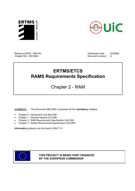
ERTMS/ETCS RAMS Requirements Specification Chapter 2 - RAM
ERTMS/ETCS RAMS Requirements Specification Chapter 2 - RAM
ERTMS/ETCS RAMS Requirements Specification Chapter 2 - RAM
- No tags were found...

You also want an ePaper? Increase the reach of your titles
YUMPU automatically turns print PDFs into web optimized ePapers that Google loves.
Reference EEIG : 96S126<strong>Chapter</strong> Ref : 02S1266-Distribution date :Document version :30/09/986-<strong>ERTMS</strong>/<strong>ETCS</strong><strong><strong>RAM</strong>S</strong> <strong>Requirements</strong> <strong>Specification</strong><strong>Chapter</strong> 2 - <strong>RAM</strong>COMMENT:This document (96s1266-) comprises of four mandatory chapters:• <strong>Chapter</strong> 0 - Introduction Unit 96s1266-• <strong>Chapter</strong> 1 - General Aspects 01s1266-• <strong>Chapter</strong> 2 - <strong>RAM</strong> <strong>Requirements</strong> <strong>Specification</strong> 02s1266-• <strong>Chapter</strong> 3 - Safety <strong>Requirements</strong> <strong>Specification</strong> 03s1266-Informative guidance can be found in 98s7111-THIS PROJECT IS BEING PART FINANCEDBY THE EUROPEAN COMMISSION
EEIG <strong>ERTMS</strong> Users GroupVERSIONS & MODIFICATIONSVersionNb1-Date ofdistribution15/05/1996Comments on the modificationFirst issueResponsible forthe modificationM. B.2-30/05/1996Preliminary Overall <strong><strong>RAM</strong>S</strong> <strong>Requirements</strong>M. B.3-28/06/1996+ Preliminary ApportionmentM. B.4-19/09/1996Modified version: accepted comments, compliance withavailable <strong>ERTMS</strong> <strong>Specification</strong>sM. B.5-20/12/1996Final version: agreed by national railways, integratingthe <strong><strong>RAM</strong>S</strong> Workshop with Eurosig agreed resultsM. B.6-30/09/98Including the agreed modifications in the databaseM. B.APPROVALThis document is approved by :Title Name Signature<strong><strong>RAM</strong>S</strong> ManagerM. BERIEAUSystem DirectorF. HEIJNENThis document is controlled by :Title Name SignatureQuality DirectorA. JANHSENThis document is authorised for distribution by :Title Name SignatureManaging DirectorJ. PELLEGRINDoc. Ref.: 02s1266- page 2/83
EEIG <strong>ERTMS</strong> Users GroupTABLE OF CONTENTS<strong>Chapter</strong> 22.0. REFERENCES......................................................................................................................................52.1. <strong>ERTMS</strong> PRELIMINARY <strong>RAM</strong> RELATED ANALYSES ..........................................................................82.1.1 PRELIMINARY <strong>RAM</strong> ANALYSIS....................................................................................................102.1.1.1 System Identification................................................................................................................102.1.1.2 Mission of the System..............................................................................................................102.1.1.3 Operating Conditions: Application Levels..................................................................................102.1.1.4 Environmental and Maintenance Conditions.............................................................................102.1.1.5 Failure Conditions ....................................................................................................................112.1.2 <strong>RAM</strong> V&V: OVERVIEW OF THE <strong>RAM</strong> PROG<strong>RAM</strong>........................................................................112.2. <strong>ERTMS</strong> OVERALL <strong>RAM</strong> REQUIREMENTS........................................................................................132.2.1 MISSION PROFILE OF THE <strong>ERTMS</strong> SYSTEM.............................................................................132.2.1.1 Mission of the <strong>ERTMS</strong>/<strong>ETCS</strong>...................................................................................................142.2.1.2 Environmental Conditions.........................................................................................................152.2.1.3 Maintenance Conditions...........................................................................................................152.2.1.4 Operating Conditions ...............................................................................................................172.2.2 SYSTEM <strong>RAM</strong> REQUIREMENTS ..................................................................................................202.2.2.1 <strong>ERTMS</strong> Availability Targets......................................................................................................212.2.2.2 <strong>ERTMS</strong> Mission Reliability Targets ..........................................................................................232.2.2.3 <strong>ERTMS</strong> Maintainability Targets ................................................................................................262.2.2.4 <strong>ERTMS</strong> Logistic Support Constraints .......................................................................................292.2.3 <strong>RAM</strong> VERIFICATION AND VALIDATION.......................................................................................312.2.3.1 Acceptance Criteria..................................................................................................................322.2.3.2 V&V Program...........................................................................................................................382.3. APPORTIONMENT OF <strong>RAM</strong> TARGETS ............................................................................................402.3.1 <strong>ERTMS</strong> FUNCTIONAL ANALYSIS.................................................................................................402.3.2 CONTRIBUTIONS TO THE <strong>ERTMS</strong>/<strong>ETCS</strong> OPERATIONAL AVAILABILITY..................................402.3.2.1 Hardware Contribution .............................................................................................................402.3.2.2 Transmission Errors Contribution .............................................................................................422.3.3 <strong>ERTMS</strong> (UN)AVAILABILITY REQUIREMENTS FOR CONSTITUENTS.........................................442.3.4 <strong>ERTMS</strong> FUNCTIONS <strong>RAM</strong>-BASED ALLOCATION OF SOFTWARE INTEGRITY LEVELS...........452.3.4.1 <strong>RAM</strong>-based IL determination....................................................................................................462.3.4.2 <strong>ERTMS</strong> Functions Weakness Estimation <strong>Requirements</strong>...........................................................472.3.5 REQUIREMENTS FOR THE <strong>ERTMS</strong> SOFTWARE INTEGRITY LEVELS APPORTIONMENT......472.4. SYSTEM <strong>RAM</strong> PROG<strong>RAM</strong>ME PLAN REQUIREMENTS ....................................................................492.4.1 GENERAL......................................................................................................................................492.4.1.1 Purpose ...................................................................................................................................492.4.1.2 Scope ......................................................................................................................................492.4.1.3 <strong>RAM</strong> Structure and Responsibilities .........................................................................................502.4.1.4 <strong>RAM</strong> <strong>Requirements</strong>..................................................................................................................502.4.1.5 <strong>RAM</strong> Programme Plan .............................................................................................................512.4.1.6 System Conditions and Mission Profile.....................................................................................512.4.1.7 System Analysis ......................................................................................................................522.4.2 RELIABILITY PROG<strong>RAM</strong>ME SPECIFICITIES ...............................................................................522.4.2.1 Reliability Programme Reviews................................................................................................522.4.2.2 Reliability Modelling, Prediction and Apportionment..................................................................532.4.2.3 FMECA analysis ......................................................................................................................542.4.2.4 Critical Items List......................................................................................................................542.4.2.5 Software Reliability Estimation .................................................................................................552.4.2.6 Reliability Preliminary Tests .....................................................................................................552.4.2.7 Reliability Demonstration Testing Plan .....................................................................................562.4.2.8 Reliability Demonstration Tests ................................................................................................572.4.2.9 Failure data collection from the field (FRACAS)........................................................................57Doc. Ref.: 02s1266- page 3/83
EEIG <strong>ERTMS</strong> Users Group2.4.3 MAINTAINABILITY PROG<strong>RAM</strong>ME SPECIFICITIES ......................................................................582.4.3.1 Maintainability Programme Reviews.........................................................................................582.4.3.2 Preventive Maintenance Analysis.............................................................................................582.4.3.3 Corrective Maintenance Analysis .............................................................................................592.4.3.4 Fault Isolation and Trouble-Shooting Plan ................................................................................592.4.3.5 Maintainability Qualification Tests ............................................................................................602.4.3.6 Maintainability Demonstration Testing Plan ..............................................................................602.4.3.7 Maintainability Demonstration Tests.........................................................................................612.4.4 OPERATIONAL AVAILABILITY ASSESSMENT.............................................................................622.4.5 INTERRELATIONSHIPS WITH THE SYSTEM QUALITY PLAN ....................................................632.4.5.1 Preliminary Design Review.......................................................................................................632.4.5.2 Critical Design Review .............................................................................................................642.4.5.3 Test Readiness Review ...........................................................................................................652.4.5.4 Production Readiness Review..................................................................................................65Doc. Ref.: 02s1266- page 4/83
EEIG <strong>ERTMS</strong> Users Group2.0. REFERENCESThe complete list of References is presented in <strong>Chapter</strong> 0 - Introduction Unit. Thefollowing references apply to this chapter only.[2.1] UIC/ERRI "<strong>ETCS</strong> - FRS Functional <strong>Requirements</strong><strong>Specification</strong>",Version 4.01Mandatory[2.2] EEIG <strong>ERTMS</strong> USERS GROUP "<strong>ERTMS</strong> <strong><strong>RAM</strong>S</strong> -Informative part”, 98S711,Version 1Informative[2.3] EEIG <strong>ERTMS</strong> USERS GROUP" <strong>ERTMS</strong> Environmental Conditions, Version 5Mandatory[2.4] EEIG <strong>ERTMS</strong> USERS GROUP "<strong>ERTMS</strong>/<strong>ETCS</strong> - <strong>Specification</strong> of Service<strong>Requirements</strong>", included in [2.2]Informative[2.5] EN 50126 "Railway Applications - The <strong>Specification</strong> andDemonstration of Dependability, Reliability,Availability, Maintainability and Safety (<strong><strong>RAM</strong>S</strong>)",CENELECNormative[2.6] EN 50128 "Railway Applications - Software for RailwayControl and Protection Systems",CENELECNormative[2.7] EN50159-2 "Railway Applications - <strong>Requirements</strong> for Safety-Related Communication in Open Transmissionsystems",CENELECNormativeDoc. Ref.: 02s1266- page 5/83
EEIG <strong>ERTMS</strong> Users Group[2.8] EN 29000-3 "Quality Management and Quality AssuranceStandards - Guidelines for the Application ofISO9001 to the development, supply andmaintenance of software",CEN, First Version, June 1993Normative[2.9] ISO/IEC DIS 9126 "Information Technology - Software Product andEvaluation - Quality Characteristics andGuidelines for their Use",ISO/IEC JTC-1, Draft, 1990Informative[2.10]MIL-STD-756B"Reliability Modelling and Prediction",USA DoD, 18 November 1991Informative[2.11]MIL-STD-781D"Reliability Testing for Engineering Development,Qualification and Production",USA DoD, 17 October 1986Informative[2.12]MIL-STD-785B"Reliability Program for System and EquipmentDevelopment and Production",USA DoD, 15 September 1980Informative[2.13]MIL-STD-470B"Maintainability Program for Systems andEquipment",USA DoD, 30 May 1989Informative[2.14]MIL-STD-471A"MaintainabilityVerification/Demonstration/Evaluation",USA DoD, 27 March 1973InformativeDoc. Ref.: 02s1266- page 6/83
EEIG <strong>ERTMS</strong> Users Group[2.15]MIL-HDBK-472"Maintainability Prediction - Handbook",USA DoD, 24 May 1966Informative[2.16]MIL-STD-1629A"Procedures for Performing a Failure Mode,Effects and Criticality Analysis",USA DoD, 24 November 1980Informative[2.17]EEIG <strong>ERTMS</strong> USERS GROUP“Engineering documents and Eurosig documents”List in Contents.xls CDROM 31/07 98Mandatory[2.18] UIC/ERRI "<strong>ETCS</strong> <strong>RAM</strong> Strategy",Final Draft, 28 July 1995Informative[2.19] Book Michael R. Lyu,"Handbook of Software Reliability Engineering",IEEE Computer Society Press, McGraw-Hill, 1996ISBN 0-07-039400-8InformativeDoc. Ref.: 02s1266- page 7/83
EEIG <strong>ERTMS</strong> Users Group2.1. <strong>ERTMS</strong> PRELIMINARY <strong>RAM</strong> RELATED ANALYSESThe preliminary <strong>RAM</strong> related activities have the purpose of identifying the applicationenvironment of the <strong>ERTMS</strong>/<strong>ETCS</strong> system, in order to recognise the fundamental conceptswhich the overall <strong>RAM</strong> requirements have to be based on.In this preliminary activities will be developed the following aspects:−−similar systems review: a list of the existing European Signalling Systems,applicable for providing suitable <strong>RAM</strong>-related information, is made;preliminary system analysis: the <strong>ERTMS</strong>/<strong>ETCS</strong> available documentation isreviewed in order to define, at a preliminary level, the overall system structureand its mission profile and to recognise the system failure conditions.The outputs of these preliminary <strong>RAM</strong> related activities constitute the backgroundnecessary for defining the Overall <strong>RAM</strong> <strong>Requirements</strong> <strong>Specification</strong> in terms of:−−−overall <strong>RAM</strong> requirements;overall demonstration and acceptance criteria;overall <strong>RAM</strong> programme requirements.The preliminary <strong>RAM</strong> related activities consist in investigating all the EEIG <strong>ERTMS</strong> UsersGroup documentation, relevant to the <strong>ERTMS</strong>/<strong>ETCS</strong> specifications, in order to recogniseall the functional requirements which may affect, both directly or indirectly, the <strong>RAM</strong>performances of the system.The following outputs constitute the preliminary <strong>RAM</strong> related activities results:1. System identification. The system has to be identified in terms of boundarylimits, operation conditions, functions, interfaces and architecture.2. Failure conditions. The failures of the system has to be identified andcategorised in order to define appropriate requirements.This paragraph intends to summarise the experiences carried out by EuropeanRailways on technologies similar to those utilised for the <strong>ERTMS</strong>/<strong>ETCS</strong> system. Thisreferences are useful for recognising <strong>RAM</strong>-related information in existing and operatingsignalling systems in order to improve the accuracy of the <strong>RAM</strong> parameters estimationDoc. Ref.: 02s1266- page 8/83
EEIG <strong>ERTMS</strong> Users Groupand to draw up credible and reachable <strong>RAM</strong> performances for the whole <strong>ERTMS</strong>/<strong>ETCS</strong>system.In the following, some of the main experiences in Europe for the technologies employedin the <strong>ERTMS</strong>/<strong>ETCS</strong> are summarised.−Trackside equipment:Loop and Short Track circuit: 1. German railways continuous signallingsystem LZB.2. French railways TVM-300 and TVM-430systems.Balise: 1. Italian railways experimental system ATC(RSDD) installed on the Cremona-Treviglioline.2. Swedish, Norwegian and French railwaysKVB system.−Train detection and integrity:OnBoard equipment:national experiences matured on specifictrackside Train Detection and Integrity systems.This is mandatory for the <strong>ERTMS</strong> ApplicationLevel 1 and 2 where Train Detection and TrainIntegrity are based on existing systems.individual experiences matured on specificonboard equipment of national signalling systems:speed control, odometry, ATO/ATP, train integrity(only for Level 3).−GSM Radio:no experiences are at present recognisable inEuropean Railways at an acceptable experiencelevel. The experience which may be taken underconsideration is that one matured in GSM phonecommunications.Doc. Ref.: 02s1266- page 9/83
EEIG <strong>ERTMS</strong> Users Group2.1.1 PRELIMINARY <strong>RAM</strong> ANALYSISThis preliminary analysis aims at defining the inputs for the Overall <strong>ERTMS</strong>/<strong>ETCS</strong> <strong>RAM</strong><strong>Requirements</strong> <strong>Specification</strong>.Such inputs are composed by the following information:−technical information for the definition of the <strong>ERTMS</strong>/<strong>ETCS</strong> mission profileincluding system boundary limits and operating, environmental andmaintenance conditions;− definition of the failure conditions of the system.2.1.1.1 System IdentificationThe architecture of the <strong>ERTMS</strong>/<strong>ETCS</strong>, identifying its main subsystems andconstituents in order to provide an input for the activity of defining the boundarylimits of the system and then univocally defining the scope of the <strong>RAM</strong> <strong>Requirements</strong><strong>Specification</strong>, is defined in the <strong>ERTMS</strong> Users Group document : 96e0148- [2.17]2.1.1.2 Mission of the SystemThe mission of the <strong>ERTMS</strong>/<strong>ETCS</strong> is to supervise, at different levels of application,the movement of trains ensuring their safe running on different European railwaynetworks [2.17]2.1.1.3 Operating Conditions: Application LevelsThe <strong>ERTMS</strong>/<strong>ETCS</strong> operating conditions depending of the Application Levels aredescribed in the <strong>ERTMS</strong> Users Group document : 96e0136- [2.17]2.1.1.4 Environmental and Maintenance ConditionsThe <strong>ERTMS</strong> Environmental Conditions are described in [2.3].Maintenance conditions have to constitute a not negligible subset of the<strong>ERTMS</strong>/<strong>ETCS</strong> mission profile.In the context of <strong>ERTMS</strong>/<strong>ETCS</strong>, the reference maintenance conditions has to beidentified in that common principle to be taken into account by the nationalmaintenance systems for allowing the operational and/or technical interoperabilityaccording to the specific Level of Application.In particular, an adequate availability of spare parts for <strong>ERTMS</strong> equipped foreigntrains has to be ensured by each national maintenance system for <strong>ERTMS</strong> equippedlines.Doc. Ref.: 02s1266- page 10/83
EEIG <strong>ERTMS</strong> Users GroupOther principles, regarding diagnostics, trackside and onboard equipment standstilltime constraints and software, are defined in [2.4].2.1.1.5 Failure ConditionsThe following general failure conditions may be defined for the <strong>ERTMS</strong>/<strong>ETCS</strong>according to the general failure conditions which may be experienced by a genericguided transport system.• Immobilising failure• Service failure• Minor FailureThe above conditions, defined in the Glossary of <strong>Chapter</strong> 0 - Introductory Unit,constitute the input for establishing the criticality of the <strong>ERTMS</strong>/<strong>ETCS</strong> failures inreason of their impact on the general failure conditions. On the basis of the <strong>RAM</strong>strategy, this input will allow to differentiate <strong>RAM</strong> requirements for failurescharacterised by different criticality.2.1.2 <strong>RAM</strong> V&V: OVERVIEW OF THE <strong>RAM</strong> PROG<strong>RAM</strong>Aim of the <strong>RAM</strong> Programme is of ensuring, by means of verification, validation anddemonstration activities, that the <strong>RAM</strong> <strong>Requirements</strong> are properly achieved.The <strong>RAM</strong> Programme may be organised in the following subprograms:• Reliability Programme:has the purpose of ensuring, during the design and evaluation phases, thatthe reliability targets are achieved.• Maintainability Programme:has the purpose of ensuring, during the design and evaluation phases, thatthe maintainability targets are achieved.• Reliability Demonstration Programme:has the purpose of demonstrating, by means of field testing, that thereliability targets are achieved.• Maintainability Demonstration Programme:has the purpose of demonstrating, by means of field testing, that themaintainability targets are achieved.Doc. Ref.: 02s1266- page 11/83
EEIG <strong>ERTMS</strong> Users GroupThe <strong>ERTMS</strong>/<strong>ETCS</strong> <strong>RAM</strong> Programme shall include, as a minimum, the followingactivities:• <strong>RAM</strong> Programme Planning;• System conditions and mission profile;• Periodical <strong>RAM</strong> Programme reviews;• Reliability modelling, prediction and apportionment;• FMECA analysis;• Software reliability analysis;• Service dependability analysis and verification;• Preventive maintenance analysis;• Corrective maintenance analysis;• Fault isolation and trouble-shooting plans;• Reliability development/growth testing programme;• Maintainability preliminary tests;• Reliability demonstration tests;• Maintainability demonstration tests;• Failure data collection from the field (FRACAS).The above list defines the minimum requirements for a <strong>RAM</strong> Programme for a systemincluding hardware and software. A <strong>RAM</strong> Programme <strong>Specification</strong> will be tailored tothe particular application and the relevant activities will be detailed in the<strong>ERTMS</strong>/<strong>ETCS</strong> <strong>RAM</strong> <strong>Requirements</strong> <strong>Specification</strong>.Doc. Ref.: 02s1266- page 12/83
EEIG <strong>ERTMS</strong> Users Group2.2. <strong>ERTMS</strong> OVERALL <strong>RAM</strong> REQUIREMENTSThis chapter aims to define the contents of the <strong>ERTMS</strong> <strong><strong>RAM</strong>S</strong> <strong>Requirements</strong> <strong>Specification</strong>which state the Overall <strong>RAM</strong> <strong>Requirements</strong> for the <strong>ERTMS</strong>/<strong>ETCS</strong> system.The Overall <strong>RAM</strong> <strong>Requirements</strong> are defined in accordance with CENELEC EN50126 onthe basis of the principles established in [2.18] and of the currently available<strong>ERTMS</strong>/<strong>ETCS</strong> controlled, where applicable, documentation.For better addressing system requirements along the text of the document, they areidentified by placing the symbol ® at the left margin of the first line of the relevantparagraph. For more information about the use of the requirements marked with ®, referto §2.3.3.As stated in the CENELEC EN50126, the <strong>ERTMS</strong>/<strong>ETCS</strong> Overall <strong>RAM</strong> <strong>Requirements</strong><strong>Specification</strong> is organised in the following four sections:• Mission Profile identification• Overall <strong>RAM</strong> <strong>Requirements</strong> definition• Overall <strong>RAM</strong> Verification and Validation criteria• Overall <strong>RAM</strong> Programme requirementsThe specified Overall <strong>RAM</strong> <strong>Requirements</strong>, including Mission Profile, <strong>RAM</strong> <strong>Requirements</strong>,V&V criteria and <strong>RAM</strong> Programme requirements, will constitute the baseline forapportioning <strong>RAM</strong> <strong>Requirements</strong> to the <strong>ERTMS</strong>/<strong>ETCS</strong> subsystems and for defining the<strong>ERTMS</strong> Subsystem <strong>RAM</strong> <strong>Requirements</strong> <strong>Specification</strong>.2.2.1 MISSION PROFILE OF THE <strong>ERTMS</strong> SYSTEMThe <strong>ERTMS</strong>/<strong>ETCS</strong> mission profile defines the conditions under which the system isrequired to accomplish its mission. Those conditions constitute the reference conditionsfor:1. defining the <strong>ERTMS</strong>/<strong>ETCS</strong> system <strong>RAM</strong> requirements up to the System<strong>Requirements</strong> Apportionment phase of the system Lifecycle;2. demonstrating, by analysis and tests, that each specific implementation fulfilsthe above requirements in all the Lifecycle phases starting from the Design andImplementation phase.Doc. Ref.: 02s1266- page 13/83
EEIG <strong>ERTMS</strong> Users Group2.2.1.1 Mission of the <strong>ERTMS</strong>/<strong>ETCS</strong>The <strong>ERTMS</strong>/<strong>ETCS</strong> mission has been identified in § 2.1.1.2..2.2.1.1.1 <strong>ERTMS</strong>/<strong>ETCS</strong> ScopeThe target system is defined, in the <strong>RAM</strong> <strong>Requirements</strong> <strong>Specification</strong> context, asfollows:• 1 <strong>ERTMS</strong>/<strong>ETCS</strong> equipped train plus all the <strong>ERTMS</strong>/<strong>ETCS</strong> trackside andlineside equipment encountered during 1 hour of trip in the worst case (at themaximum allowed speed in european railways of 500 km/h considering themost complex possible configuration);It is important to identify in this context the boundary limits of the <strong>ERTMS</strong>/<strong>ETCS</strong>equipment, establishing in this way the scope of the <strong>RAM</strong> <strong>Requirements</strong> definedin this specification.In § 2.1.1.1. the constituents which compose the <strong>ERTMS</strong>/<strong>ETCS</strong> categorised inTrainborne and Trackside equipment are identified.The following functional boundary limits are defined for <strong>ERTMS</strong>/<strong>ETCS</strong> [2.17]:1. Traffic regulation does not form part of the system. It forms part of an externalsystem taking into consideration national peculiarities. It is not mandatory for itto be linked with the <strong>ERTMS</strong>/<strong>ETCS</strong> system. However, an interface between theregulation system and <strong>ERTMS</strong>/<strong>ETCS</strong> must be provided in order to:• communicate to <strong>ERTMS</strong>/<strong>ETCS</strong>, and ultimately to the train, driving advisesdrawn up by the regulation intended to optimise the traffic flow;• inform the regulation of the train location known to <strong>ERTMS</strong>/<strong>ETCS</strong> for thereal time uptake of its regulation strategies according to environmentalconditions.2. Signal boxes do not form part of the <strong>ERTMS</strong>/<strong>ETCS</strong>, but they are interfacedwith that in order to:• communicate to <strong>ERTMS</strong>/<strong>ETCS</strong>, the positions of points or routes set or,indeed in the cases of levels 1 and 2, block conditions drawn up by existingexternal systems;Doc. Ref.: 02s1266- page 14/83
EEIG <strong>ERTMS</strong> Users Group• transmit to the signal box both information known to <strong>ERTMS</strong>/<strong>ETCS</strong> relatingto train location for the purpose of train announcements or monitoring andany other information of concerning for the signal boxes.3. Other systems interoperable with <strong>ERTMS</strong>/<strong>ETCS</strong>, like KVB, TVM, LZB, BACC,TBL and so on, do not form part of <strong>ERTMS</strong>/<strong>ETCS</strong> itself, but an interfacebetween <strong>ERTMS</strong>/<strong>ETCS</strong> and those systems has to be provided (STM) in orderto make as transparent as possible the running of <strong>ERTMS</strong> equipped trains onnot-equipped lines.4. Additional systems like fault detectors, announcement systems and so on, areto be considered outside <strong>ERTMS</strong>/<strong>ETCS</strong> and will be provided with appropriatestandardised interfaces with this one.5. The links between the regulation system and signal boxes do not form part of<strong>ERTMS</strong>/<strong>ETCS</strong>.2.2.1.2 Environmental ConditionsThe environmental conditions under which the <strong>ERTMS</strong>/<strong>ETCS</strong> is called to operate arespecified in the <strong>ERTMS</strong> Environmental Conditions (97s066 V5-).The <strong>RAM</strong> <strong>Requirements</strong> defined in this specification refer to the aboveenvironmental conditions.Those environmental conditions shall constitute the reference conditions forperforming the reliability analyses, for reliability verification and validation, and thereliability demonstration tests planned in the <strong>ERTMS</strong>/<strong>ETCS</strong> <strong>RAM</strong> Programme Plan.2.2.1.3 Maintenance ConditionsThe <strong>ERTMS</strong>/<strong>ETCS</strong> Maintenance Conditions relates to the Maintenance Systemdefined in the <strong>Specification</strong>s for "Service and Repair" of the <strong>ETCS</strong>-System [2.4].The document [2.4] adds to the qualitative requirements, partially covered by thisspecification in § 2.2.2.3.1. and relevant to the construction principles for the<strong>ERTMS</strong>/<strong>ETCS</strong> installations, general requirements for the <strong>ERTMS</strong>/<strong>ETCS</strong>Maintenance System as far as the maintenance documentation, the diagnosticand test equipment and the availability of spare parts are concerned.Doc. Ref.: 02s1266- page 15/83
EEIG <strong>ERTMS</strong> Users GroupFurthermore specific requirements for software development and for the<strong>ERTMS</strong>/<strong>ETCS</strong> documentation are defined in [2.4].Being [2.4] the unique applicable documentation for identifying the <strong>ERTMS</strong>/<strong>ETCS</strong>Maintenance Conditions, all the <strong>RAM</strong> <strong>Requirements</strong>, both qualitative andquantitative, established in this specification are referred to the principles statedin that document.As far as the interoperability principles are concerned, the <strong>ERTMS</strong>/<strong>ETCS</strong>Maintenance System is structured as summarised in following paragraphs.Trackside EquipmentThe <strong>ERTMS</strong>/<strong>ETCS</strong> Maintenance System, for tracksideequipment, is determined by the National RailwayAuthorities responsible for the specific application.Anyway, the general requirements defined in [2.4] shall befulfilled.Onboard EquipmentThe <strong>ERTMS</strong>/<strong>ETCS</strong> Maintenance System, for onboardequipment, has to take into account the interoperabilityprinciples. Each National Railway Authority responsiblefor <strong>ERTMS</strong>/<strong>ETCS</strong> equipped lines shall define aMaintenance System able to allow faulty <strong>ERTMS</strong>/<strong>ETCS</strong>equipped vehicles being repaired regardless to theirnationality. This shall be accomplished as follows:1. by providing spare parts for exchangeable<strong>ERTMS</strong>/<strong>ETCS</strong> onboard equipment items. Theavailability of spares on stock shall be determined,and declared in terms of stocks location and of partsavailability, by the National Railway Authorityresponsible for the line operation, in order to fulfil theLogistic Support <strong>Requirements</strong> defined in thisspecification;2. by providing specific spare parts for notexchangeable <strong>ERTMS</strong>/<strong>ETCS</strong> onboard equipment lifecritical items, whose faults result in an immobilisingfailure. The availability of spares on stock shall bedetermined, and declared in terms of stocks locationand of parts availability, by the National RailwayDoc. Ref.: 02s1266- page 16/83
EEIG <strong>ERTMS</strong> Users GroupAuthority responsible for the line operation, in orderto fulfil the Logistic Support <strong>Requirements</strong> defined inthis specification;3. by providing facilities for maintain both exchangeableand not exchangeable <strong>ERTMS</strong>/<strong>ETCS</strong> onboardequipment items in workshop (Depot LevelMaintenance). The Subsystems CorrectiveMaintenance <strong>Requirements</strong> for Depot LevelMaintenance, defined later in this specification, shallbe fulfilled.The <strong>RAM</strong> <strong>Requirements</strong> defined in this <strong>Specification</strong> relates to the generalprinciples defined in [2.4] and in the current paragraph regardless to the specificnational application and, consequently, to the specific maintenance system.For <strong>RAM</strong> <strong>Requirements</strong> demonstration purposes, the specific maintenanceconditions shall be clearly defined and declared, including the location of stocksand the relevant availability of spares if applicable, at the definition of thecontracts stipulated with contractors, sub-contractors and suppliers, for the<strong>ERTMS</strong>/<strong>ETCS</strong> equipment provision, in the context of each specific nationalapplication.2.2.1.4 Operating ConditionsEach specific implementation of <strong>ERTMS</strong>/<strong>ETCS</strong> shall fulfil the Overall <strong>RAM</strong><strong>Requirements</strong> defined in this specification. For this reason, the <strong>ERTMS</strong>/<strong>ETCS</strong>subsystems <strong>RAM</strong> requirements shall relate to the worst possible case, in terms ofseverity of the operating conditions, which corresponds to the maximum level ofimplementation of the system.The <strong>ERTMS</strong>/<strong>ETCS</strong> operating conditions shall be expressed in terms of the numberof elements which may be met by one <strong>ERTMS</strong> equipped train during 1 hour of run,as done in [2.18].Doc. Ref.: 02s1266- page 17/83
EEIG <strong>ERTMS</strong> Users Group2.2.1.4.1 Reference Conditions for <strong>RAM</strong> <strong>Requirements</strong> definitionFor <strong>RAM</strong> <strong>Requirements</strong> definition purposes, the following conditions may be takenas a reference for the worst case application• Trip duration = 1hour• Train speed = 500km/h• Balise Messages = 940• Radio Messages =1200• Continuous Info Points met (RBC) = 10• Discontinuous Info Points met• (Switchable and Non-Switchable Locations) = 940• Population for each Information Point (1 each 1.25 km)LAT = 2LCU = 1• Population for each Entry/Exit Point (1 each 12.5 km)LAT = 8LCU = 1• Population for each Reset Point (1 each 1 km)LPT = 2The <strong>RAM</strong> <strong>Requirements</strong> defined, for the <strong>ERTMS</strong>/<strong>ETCS</strong> subsystems, on the basisof the above worst case operating conditions guarantee that, at less severeapplication conditions, the <strong>ERTMS</strong>/<strong>ETCS</strong> Overall <strong>RAM</strong> <strong>Requirements</strong> arecertainly fulfilled.2.2.1.4.2 Reference Conditions for <strong>RAM</strong> <strong>Requirements</strong> demonstrationFor <strong>RAM</strong> requirements demonstration purposes, the <strong>ERTMS</strong>/<strong>ETCS</strong> operatingconditions shall be dependent on the specific application.The system Operating Conditions, relevant to the specific application, shall beclearly defined in the <strong>ERTMS</strong>/<strong>ETCS</strong> <strong>RAM</strong> Programme Plan and shall constitutethe reference conditions for all the <strong>RAM</strong> V&V activities performed during thesystem Lifecycle up to the System Acceptance phase.Anyway, the application specific operating conditions shall not influence:Doc. Ref.: 02s1266- page 18/83
EEIG <strong>ERTMS</strong> Users Group• the <strong>ERTMS</strong>/<strong>ETCS</strong> Overall <strong>RAM</strong> <strong>Requirements</strong>;• the on-board part of the <strong>ERTMS</strong>/<strong>ETCS</strong> Functions <strong>RAM</strong> <strong>Requirements</strong>,defined for the worst case conditions.On the other hand, the application specific operating conditions shall influence:• the system conditions which the <strong>RAM</strong> analysis, relevant to the <strong>RAM</strong>verification, will be based on;• the test conditions for the <strong>RAM</strong> demonstration activities.Doc. Ref.: 02s1266- page 19/83
EEIG <strong>ERTMS</strong> Users Group2.2.2 SYSTEM <strong>RAM</strong> REQUIREMENTSThe <strong>ERTMS</strong>/<strong>ETCS</strong> <strong>RAM</strong> requirements are derived from [2.18] with some numeric andmethodological adjustments.These adjustments look at improving the ERRI-A200 targets, defined in [2.18], incompliance with the manufacturing cost constraints, as far as the current technologiesallow to do.Numeric adjustments regard the quantities defined for determining the <strong>ERTMS</strong>/<strong>ETCS</strong>availability target starting from schedule adherence figures. Those quantities havebeen redefined as follows:Train delayA train is considered delayed when its delay exceed 1 min.Probability parametersProbability of having a trip delay for generic causes: = 15%Probability of having delay because of technicalcauses: 40% . 15% = 6%Probability of having delay caused by SignallingSystems failures: 30% . 6% = 1,8%Probability of having delay due to <strong>ERTMS</strong>failures(P ds ): 15% . 1,8% = 0,27%Time parametersAverage trip normal duration: T dnd = = 90 minT dnAverage value for the delay (at the end of the trip): T dy = 10 minAverage duration of <strong>ERTMS</strong> failure time for eachdelayed trip:= 0,9 T dyThe above figures can be interpreted, where applicable, as schedule adherencerequirements for the <strong>ERTMS</strong>/<strong>ETCS</strong>.The methodological adjustment regards the contribution of software on the<strong>ERTMS</strong>/<strong>ETCS</strong> failures. As mentioned in [2.2, §R.1.1.], the operational availability targetis subdivided in a not quantifiable contribution, due to software, and a quantifiable onedue to hardware faults and transmission errors.Doc. Ref.: 02s1266- page 20/83
EEIG <strong>ERTMS</strong> Users GroupThe quantifiable contribution is defined as the 60% of the total downtime of the<strong>ERTMS</strong>/<strong>ETCS</strong> system and corresponds to the quantitative system requirement to bedemonstrated by analysis and testing.The not quantifiable contribution is relevant to software reliability, which involvessystematic aspects only, for which merely qualitative requirements are defined. Inparticular, the evidence of Quality Management, including the Testing Plan, shall beprovided during the design phases and the results of testing, at the different testinglevels foreseen for the application, shall demonstrate that the operational availabilitytarget is fulfilled, tacking into account the achieved quantifiable contribution.2.2.2.1 <strong>ERTMS</strong> Availability Targets2.2.2.1.1 Schedule AdherenceThis quantitative requirement relates both to the probability of having delay on atrain running due to <strong>ERTMS</strong>/<strong>ETCS</strong> unavailabilities and to the allowed mean valueof the delay itself.® The probability of having delay caused by <strong>ERTMS</strong>/<strong>ETCS</strong> failures shall be notgreater than 0.0027.® The allowed average delay per train due to <strong>ERTMS</strong>/<strong>ETCS</strong> failures, at the endof an average trip of duration of 90 min., shall be not greater than 10 min.2.2.2.1.2 Operational AvailabilityThe operational availability target is determined utilising of the formula defined in[2.2, § R.1.1.5]. on the basis of the figures stated in § 2.2.2.:Ao=TopTop+ Tfault( )Tdn + Pds ⋅ Tdy − 0. 9 ⋅ Tdy90 + 0. 0027 ⋅ 01 . ⋅10=== 0.99973T + P ⋅ T 90 + 0.0027 ⋅10dn ds dy® The operational availability of the <strong>ERTMS</strong>/<strong>ETCS</strong>, due to all the causes offailure, shall be not less than 0.99973.The quantifiable contribution, which represents the availability figure to bequantitatively demonstrated, corresponds to the 60% of the <strong>ERTMS</strong>/<strong>ETCS</strong>unavailabilities:Doc. Ref.: 02s1266- page 21/83
EEIG <strong>ERTMS</strong> Users GroupAo=TopTop+ Tfault( )T + 0. 6 ⋅ P ⋅ T − 0.9 ⋅ T=T + 0.6 ⋅ P ⋅ Tdn ds dy dydn ds dy90 + 0. 6 ⋅ 0. 0027 ⋅ 01 . ⋅10== 0.9998490 + 0. 6 ⋅ 0.0027 ⋅10® The <strong>ERTMS</strong>/<strong>ETCS</strong> quantifiable contribution to operational availability, due tohardware failures and transmission errors, shall be not less than 0.99984.2.2.2.1.3 Downtime <strong>Requirements</strong>The downtime requirements are defined in terms of the allowed mean downtimeswhich correspond to the operational availability targets defined in § 2.2.2.1.2.These downtimes, useful for demonstration purposes, can be calculated asfollows, expressed in hours on a per year basis:( )DT = 1− ⋅8760A ODoc. Ref.: 02s1266- page 22/83
EEIG <strong>ERTMS</strong> Users Group2.2.2.2 <strong>ERTMS</strong> Mission Reliability TargetsThe <strong>ERTMS</strong>/<strong>ETCS</strong> Mission Reliability Targets are composed of qualitative andquantitative requirements. Quantitative requirements are expressed in terms of MeanTime Between Failures (MTBF) and are differentiated in reason of the criticality(Immobilising, Service or Minor) of the failures under consideration. The followingprerequisites are identified:1. Immobilising Failures shall not exceed the 10% of the total amount of failureswhich affect the system operation (contributing to Operational Availability);2. Service Failures shall not exceed the 90% of the total amount of failures whichaffect the system operation (contributing to Operational Availability);3. Minor Failures shall contribute to an availability target not less than 0,995;4. the Onboard Equipment contribution is stated in the 4,34% of the total systemfailures (see [2.2])5. the Trackside Centralised Equipment contribution is stated in the 0,08% of thetotal system failures (see [2.2]);6. the Trackside Distributed Equipment (LNS) contribution is stated in the 95,58%of the total system failures);7. the Mean Time To ReStore (MTTRS) of the Onboard Equipment (ONB) is1,737 hours, the appropriate value for ensuring that the Onboard Equipmentstandstill time is less than 4 hours in the 90% of the unscheduled repairs,assuming exponentially distributed repair time (see §2.2.2.3.3.);8. the Mean Time To ReStore (MTTRS) of the Trackside Centralised Equipment(TRK) is 0,869 hours, the appropriate value for ensuring that the TracksideEquipment standstill time is less than 2 hours in the 90% of the unscheduledrepairs, assuming exponentially distributed repair time (see §2.2.2.3.3.).9. the Mean Time To ReStore (MTTRS) of the Trackside Distributed Equipment(LNS) is 1,737 hours, the appropriate value for ensuring that the TracksideEquipment standstill time is less than 4 hours in the 90% of the unscheduledrepairs, assuming exponentially distributed repair time (see §2.2.2.3.3.).2.2.2.2.1 Qualitative <strong>Requirements</strong>Reliability qualitative requirements regard mainly the requirements for theimplementation of a <strong>ERTMS</strong>/<strong>ETCS</strong> Reliability Programme as a subset of thesystem <strong>RAM</strong> Programme.Reliability qualitative requirements are particularly critical for the <strong>ERTMS</strong>/<strong>ETCS</strong>software in that they represent the only reliability requirements which can bedefined and demonstrated to be accomplished.Doc. Ref.: 02s1266- page 23/83
EEIG <strong>ERTMS</strong> Users GroupSpecific qualitative requirement, related to the <strong>ERTMS</strong>/<strong>ETCS</strong> design criteria atsystem level, are also defined.The following reliability qualitative requirements are defined at the overall <strong>RAM</strong><strong>Requirements</strong> level:® a System Reliability Programme, subset of the <strong>RAM</strong> Programme, shall beimplemented and a System Reliability Programme Plan, subset of the <strong>RAM</strong>Programme Plan, shall be produced and maintained in accordance to the <strong>RAM</strong>Programme Plan <strong>Requirements</strong> specified in § 2.4 and to the System QualityPlan of the <strong>ERTMS</strong>/<strong>ETCS</strong>.® Software Quality Assurance and V&V Programs shall be implemented incompliance with the international standards [2.6 and 2.8,] and, in particular,with [2.6] as far as software integrity is concerned. Software Quality Assuranceand V&V Plans, shall be produced and maintained in accordance to the abovestandards.® no one single fault shall cause immobilising failures as defined in § 2.2.2.2.2.® when redundancies are utilised in order to prevent single failures to causeimmobilising failures, appropriate measures which guarantee the independenceof the redunded equipment shall be adopted and documented. For redundedsafety-related functions, a Common Cause Failures Analysis shall beperformed.2.2.2.2.2 Immobilising FailuresImmobilising Failures are defined, for the <strong>ERTMS</strong>/<strong>ETCS</strong> context, in the Glossarycontained in <strong>Chapter</strong> 0.The purpose of this paragraph is to identify the <strong>ERTMS</strong>/<strong>ETCS</strong> system levelfailures which can result in one of the above conditions and to define, for thesefailures, appropriate reliability targets.In the <strong>ERTMS</strong>/<strong>ETCS</strong> context, Immobilising Failures may be identified (see [2.2]),as all the <strong>ERTMS</strong>/<strong>ETCS</strong> failures which cause two or more trains to be switched inon sight mode.Doc. Ref.: 02s1266- page 24/83
EEIG <strong>ERTMS</strong> Users GroupThe relevant mission is then defined as the <strong>ERTMS</strong>/<strong>ETCS</strong> operation in absenceof Immobilising Failures and, for that mission, the following reliability requirementsare defined:® The Mean Time Between Immobilising hardware Failures MTBF-I ONB , definedfor Onboard equipment, shall be not less than 2.7 . 10 6 hours.® The Mean Time Between Immobilising hardware Failures MTBF-I TRK , definedfor Trackside Centralised equipment, shall be not less than 3.5 . 10 8 hours.® The Mean Time Between Immobilising hardware Failures MTBF-I LNS , definedfor Lineside Distributed equipment, shall be not less than 1.2 . 10 5 hours.2.2.2.2.3 Service FailuresService Failures are defined, for the <strong>ERTMS</strong>/<strong>ETCS</strong> context, in the Glossarycontained in <strong>Chapter</strong> 0.The purpose of this paragraph is to identify the <strong>ERTMS</strong>/<strong>ETCS</strong> system levelfailures which can result in one of the above conditions and to define, for thesefailures, appropriate reliability targets.In the <strong>ERTMS</strong>/<strong>ETCS</strong> context, Service Failures may beidentified as all the<strong>ERTMS</strong>/<strong>ETCS</strong> failures which cause the nominal performance of one or moretrains to be reduced and/or at most one train to be switched in on sight mode (see[2.2]).The relevant mission is then defined as the <strong>ERTMS</strong>/<strong>ETCS</strong> operation in absenceof Service Failures and, for that mission, the following reliability requirements aredefined:® The Mean Time Between Service hardware Failures MTBF-S ONB , defined forOnboard equipment, shall be not less than 3.0 . 10 5 hours.® The Mean Time Between Service hardware Failures MTBF-S TRK , defined forTrackside Centralised equipment, shall be not less than 4.0 . 10 7 hours.® The Mean Time Between Service hardware Failures MTBF-S LNS , defined forLineside Distributed equipment, shall be not less than 1.4 . 10 4 hours.2.2.2.2.4 Minor FailuresMinor Failures are defined, for the <strong>ERTMS</strong>/<strong>ETCS</strong> context, in the Glossarycontained in <strong>Chapter</strong> 0.Doc. Ref.: 02s1266- page 25/83
EEIG <strong>ERTMS</strong> Users GroupThe purpose of this paragraph is to identify the <strong>ERTMS</strong>/<strong>ETCS</strong> system levelfailures which can result in the above condition and to define, for these failures,appropriate reliability targets.The relevant mission is then defined as the <strong>ERTMS</strong>/<strong>ETCS</strong> operation in absenceof Minor Failures and, for that mission the following reliability requirements aredefined:® The Mean Time Between Minor hardware Failures MTBF-M ONB , defined forOnboard equipment, shall be not less than 8.0 . 10 3 hours.® The Mean Time Between Minor hardware Failures MTBF-M TRK , defined forTrackside Centralised equipment, shall be not less than 1.0 . 10 5 hours.® The Mean Time Between Minor hardware Failures MTBF-M LNS , defined forLineside Distributed equipment, shall be not less than 3.6 . 10 2 hours.The above requirements are referred to the whole system, as defined in§2.2.1.1.3., and represent the mean time between any required correctivemaintenance action not involving a degradation of the system performance.2.2.2.3 <strong>ERTMS</strong> Maintainability Targets2.2.2.3.1 Qualitative <strong>Requirements</strong>The purpose of Maintainability Qualitative <strong>Requirements</strong> is to address the designtoward solutions which allow to facilitate both corrective and preventivemaintenance actions to be performed on the <strong>ERTMS</strong>/<strong>ETCS</strong> equipment andtrouble-shooting and modification activities to be performed on the <strong>ERTMS</strong>/<strong>ETCS</strong>software modules.2.2.2.3.1.1 HardwareAccessibility:The <strong>ERTMS</strong>/<strong>ETCS</strong> equipment shall be designed insuch a way that all its parts and related connectionspermit inspection, repair, revision and replacement,taking into account the dimensions of the requiredequipment.Dismounting:During a maintenance action it shall be possible todisassemble and to take out any item without beingDoc. Ref.: 02s1266- page 26/83
EEIG <strong>ERTMS</strong> Users Groupcompelled to involve other items not directly related tothe specific maintenance action.Handiness: The <strong>ERTMS</strong>/<strong>ETCS</strong> equipment subjected todisassembling related to a maintenance action shall bedesigned in order to be easily transportable. They shallnot exceed the weight established by the nationalregulatory authorities in reason of the number ofoperators assigned to its movement. They shall befitted out with appropriate devices enabling actionscarried out with hooks, anchor plates, loading forks,etc.Cleaning-friendliness:Compartments, equipment and so on, being parts of<strong>ERTMS</strong>/<strong>ETCS</strong> shall be designed in order to facilitate ata maximum all external cleaning actions.Standardisation :Early in the design phase of the <strong>ERTMS</strong>/<strong>ETCS</strong> systemLifecycle, solutions shall be applied leading to thelowest possible diversification of the <strong>ERTMS</strong>/<strong>ETCS</strong>system components. Parts interchangeability shall bemaximised making use of standardised elements wherepossible.Interchangeability:An item can be removed and another item installed inits place without affecting any equipmentcharacteristics. The replacement shall be compatible inform, fit and function.Testability:Each item belonging to the <strong>ERTMS</strong>/<strong>ETCS</strong> system shallbe provided of appropriate testability features incompliance with [2.4].2.2.2.3.1.2 SoftwareAnalysability:The <strong>ERTMS</strong>/<strong>ETCS</strong> software shall be designed in orderto minimise the effort requested for tracing defects orfailure causes and for identifying the parts to bemodified.Doc. Ref.: 02s1266- page 27/83
EEIG <strong>ERTMS</strong> Users GroupChangeability:The activities of modification and of defect removalshall be facilitated, and the effort needed for adaptingsoftware to environment changing (i.e., operatingsystem, hardware architecture, etc.) shall be minimised.Stability:The risk that undesirable effects may occur as aconsequence of a modification shall be minimised.Testability:Software testing and validation activities consequent toa modification shall be facilitated as much as possible.2.2.2.3.2 Preventive MaintenanceFor Preventive Maintenance, at system level, qualitative requirements only aredefined.® Each Contractor/Sub-contractor/Supplier responsible for the provision of<strong>ERTMS</strong>/<strong>ETCS</strong> equipment or parts, shall declare, providing appropriatedocumentation, the Preventive Maintenance <strong>Requirements</strong> necessary forensuring the required <strong>RAM</strong> Performance, as defined in this specification, forthe equipment under its competency.® The Preventive Maintenance <strong>Requirements</strong>, defined by each Contractor/Subcontractor/Suppliershall comply with the Logistic Support <strong>Requirements</strong>defined in this specification and shall require the agreement of the CustomerProject Management for becoming effective requirements to be verified anddemonstrated in the further phases of the System Lifecycle by means ofappropriate activities of the <strong>RAM</strong> Programme.2.2.2.3.3 Corrective MaintenanceThe Corrective Maintenance <strong>Requirements</strong> are subdivided in two categories:General Quantitative <strong>Requirements</strong> and Specific Quantitative <strong>Requirements</strong>.• General Corrective Maintenance Quantitative <strong>Requirements</strong> regard themaximum standstill times tolerable in the case of any unscheduled repairs;they represent operative requirements [2.4].• Specific Corrective Maintenance Quantitative <strong>Requirements</strong> regard the allowedtimes for detecting/locating faults, replacing faulty modules and restarting thesystem interested by the failure occurred; they represent design requirementsDoc. Ref.: 02s1266- page 28/83
EEIG <strong>ERTMS</strong> Users Groupto be fulfilled and demonstrated by the Contractor/Sub-Contractor(s)/Supplier(s) responsible for providing <strong>ERTMS</strong>/<strong>ETCS</strong> equipment.The following General Corrective Maintenance Quantitative <strong>Requirements</strong> aredefined for <strong>ERTMS</strong>/<strong>ETCS</strong> (see [2.4]):Maximum standstill time tolerable for the 90% of theunscheduled repairs of onboard equipment:Maximum standstill time tolerable for the 90% of theunscheduled repairs of trackside centralisedequipment:Maximum standstill time tolerable for the 90% of theunscheduled repairs of trackside distributed (lineside)equipment:4 hours2 hours4 hoursThe following Specific Corrective Maintenance Quantitative <strong>Requirements</strong> aredefined for <strong>ERTMS</strong>/<strong>ETCS</strong>:® The maximum amount of time for detecting/isolating/replacing a faulty itemshall not exceed, in the 90% of the cases, the 65% of the maximum tolerablestandstill time defined for the relevant equipment2.2.2.4 <strong>ERTMS</strong> Logistic Support Constraints2.2.2.4.1 Maintenance CostThe maintenance cost constraints shall be defined by the national regulatoryauthorities responsible for each specific application of <strong>ERTMS</strong>/<strong>ETCS</strong> in reason ofthe Level of Application chosen.The <strong>ERTMS</strong>/<strong>ETCS</strong> maintenance cost constraints shall be expressed in terms ofthe maximum allowed percentage of the whole system Lifecycle Cost to beexpended for:• training of the maintenance personnel;• preventive, scheduled and corrective maintenance actions including thecost of the personnel employed;• travel costs sustained for reaching the maintenance sites;• spare parts acquisition, provision and storage;• assistance contracts with suppliers of commercial computer systems.Doc. Ref.: 02s1266- page 29/83
EEIG <strong>ERTMS</strong> Users Group® The maintenance cost of <strong>ERTMS</strong>/<strong>ETCS</strong> shall not exceed the 2% per year ofthe System acquisition Cost, for a duration of 30 years of the <strong>ERTMS</strong>/<strong>ETCS</strong>Lifecycle.2.2.2.4.2 Supply and Administrative DelayThe fulfilment of the constraints related to the maximum allowed delays onmaintenance actions, due to administrative causes, is responsibility of thenational regulatory authorities responsible for each specific application of<strong>ERTMS</strong>/<strong>ETCS</strong> in reason of the Level of Application chosen.The following constraints need to be guaranteed at least in the 90% of theoccurrences, for ensuring the effective fulfilment of the technical <strong>RAM</strong>requirements:1. The maximum amount of time necessary to inform a maintenance stafffor performing on-site maintenance action, cannot exceed the 5% of themaximum tolerable standstill time defined for the interested equipment. Thisrequirement is valid both if the advice to the maintenance staff is automaticallyproduced by the diagnostics and if it is given manually.2. The maximum amount of time necessary to reach the maintenance site cannotexceed the 30% of the maximum tolerable standstill time defined for theinterested equipment.2.2.2.4.3 Spare Parts AvailabilityThe Contractor shall guarantee the supplying of spare parts for all the <strong>ERTMS</strong>/<strong>ETCS</strong>equipment for the entire system Lifecycle duration agreed by the parts of the contract.The Contractor shall submit for approval a Parts Provisioning Plan to the Customer.The Parts Provisioning Plan shall detail, for each of the items identified by means of theSystem Analysis (see § 2.4.1.7.), the way by which the Contractor shall guarantee theavailability of Spare Parts in reason of the relevant MTBF.The constraints related to the availability of Spare Parts on stock shall be defined bythe national regulatory authorities responsible for each specific application of<strong>ERTMS</strong>/<strong>ETCS</strong> in reason of the Level of Application chosen.When a national railway will accept <strong>ERTMS</strong>/<strong>ETCS</strong> equipped foreign vehicles on its<strong>ERTMS</strong>/<strong>ETCS</strong> equipped lines, it shall ensure, jointly with the train operator, that spareDoc. Ref.: 02s1266- page 30/83
EEIG <strong>ERTMS</strong> Users Groupparts are available for foreign vehicles so that depot level maintenance actions can beperformed when failures to the <strong>ERTMS</strong>/<strong>ETCS</strong> equipment occur. The relevant detailsshall be agreed by the railways called to exchange vehicles.2.2.3 <strong>RAM</strong> VERIFICATION AND VALIDATIONIn this paragraph, the basic principles for the demonstration of compliance with theSystem <strong>RAM</strong> <strong>Requirements</strong> for the <strong>ERTMS</strong>/<strong>ETCS</strong> system are defined in accordance to[2.5], [2.6], and to the <strong>ERTMS</strong>/<strong>ETCS</strong> Validation Procedures.Specifities for the <strong>RAM</strong> Verification and Validation, including the relevant managementstructure, shall be agreed between the parts in specific supply contracts for specificnational applications on the basis of the relevant national regulations and of thenational Railway Authorities needs.The above specificities shall be clearly defined and declared in the specific supplycontracts.At system level, the <strong>RAM</strong> Validation is based on the evaluation of the <strong>RAM</strong>Demonstration Test results or, where testing is not applicable for practical oreconomical reasons, of the documental proof of the fulfilment of <strong>RAM</strong> targets, in orderto establish the compliance with the System <strong>RAM</strong> <strong>Requirements</strong>, as defined in thepresent section of the ERMTS Control/Command <strong>RAM</strong> <strong>Requirements</strong> <strong>Specification</strong>.Details about the <strong>RAM</strong> Validation will be provided in the context of the <strong>ERTMS</strong>/<strong>ETCS</strong>Test <strong>Specification</strong> including:− Test duration− Test environment− Test conditions− Equipment subject to test− Confidence intervals for testing− Other demonstration methods and details for not cost-effectively testableequipment (e.g. documental proof)− Organisational structure of the Test Case (e.g. subjects responsible formaintenance, logistic support, and so on)− Roles and responsibilities− Other detailsThe output of this activity is the Validation of the system as far as the <strong>RAM</strong> aspects areconcerned.Doc. Ref.: 02s1266- page 31/83
EEIG <strong>ERTMS</strong> Users Group2.2.3.1 Acceptance Criteria2.2.3.1.1 Reliability Acceptance CriteriaThe reliability acceptance is conditioned to the adequacy of the <strong>RAM</strong> ValidationReport, issued by the Validation Team, which purpose is to document thesuccess, or the unsuccess, of the Reliability Demonstration Tests or of thedocumental proof, where applicable, as stated in the <strong>ERTMS</strong>/<strong>ETCS</strong> Test<strong>Specification</strong>.The Reliability Demonstration Tests shall be considered as successful if thefollowing conditions are respected:® the <strong>ERTMS</strong>/<strong>ETCS</strong> Qualitative Mission Reliability Targets defined at §2.2.2.2.1. and the Quantitative Mission Reliability Targets defined at §2.2.2.2.2., § 2.2.2.2.3. and § 2.2.2.2.4. are fulfilled;® all the <strong>ERTMS</strong>/<strong>ETCS</strong> equipment have been operated in the specifiedconditions (as defined in § 2.2.1.1., § 2.2.1.2., § 2.2.1.3. and § 2.2.1.4.2.) forthe specified testing time.The documental proof shall be considered as successful if also all the relevantconditions stated in the Test <strong>Specification</strong> are fulfilled.If the Reliability Demonstration Test or the documental proof, where applicable,are unsuccessful, the Validation Team will identify the responsibility of the nonconformityand will require appropriate corrective actions.In case the responsibility is recognised in the system operator activity, forinstance due to wrong or missing preventive maintenance, any intervention of theContractor is required and the relevant corrective actions shall be responsibility ofthe system operator.Otherwise, the Contractor responsible for the system provisioning shall require tothe appropriate Sub-Contractor(s)/Supplier(s) and, if necessary, shall perform,appropriate modifications able to improve the System Reliability for complyingwith the specified targets.Doc. Ref.: 02s1266- page 32/83
EEIG <strong>ERTMS</strong> Users GroupThe measures to be adopted for performing the above modifications shall beproposed by the Contractor responsible and agreed by the Customer ProjectManagement.2.2.3.1.1.1 Chargeable failuresThe following failures shall be considered as chargeable, for the Contractor, forthe Reliability Demonstration:− failures occurred during the system operation under the rated conditions;− failures due to wrong operation, unappropriate maintenance actions oruncorrect test procedures clearly traceable to Sub-Contractor(s)/Supplier(s)deficiences;− missed planning of scheduled maintenance of items for which a time limit isforeseen in the Preventive Maintenance Plan.2.2.3.1.1.2 Unchargeable failuresThe following failures shall be considered as not chargeable, for the Contractor,for the Reliability Demonstration:− induced faults;− faults due to human errors;− failures to accidental events;− faults occurred during the operation out of the rated system conditions;− degrade of items subject to wear for which sheduled maintenance actionshas been performed in a wrong way or have not been performed.2.2.3.1.2 Maintainability Acceptance CriteriaThe maintainability acceptance is conditioned adequacy of the <strong>RAM</strong> ValidationReport, issued by the Validation Team, which purpose is to document thesuccess, or the unsuccess, of the Maintainability Demonstration Tests.The Maintainability Demonstration Tests shall be considered as successful if thefollowing conditions are respected:® the <strong>ERTMS</strong>/<strong>ETCS</strong> Qualitative Maintainability <strong>Requirements</strong> defined at §2.2.2.3.1. are fulfilled® the Quantitative Preventive Maintenance Targets agreed as described at §2.2.2.3.2. by the Project Management as a result of the PreventiveMaintenance Analysis and the Quantitative Corrective Maintenance Targets,Doc. Ref.: 02s1266- page 33/83
EEIG <strong>ERTMS</strong> Users Groupboth defined at § 2.2.2.3.3. and resulting from the Corrective MaintenanceAnalysis, are fulfilled;® all the <strong>ERTMS</strong>/<strong>ETCS</strong> equipment have been operated in the specifiedconditions (as defined in § 2.2.1.1., § 2.2.1.2., § 2.2.1.3. and § 2.2.1.4.2.) forthe specified testing time.If the Maintainability Demonstration Tests are unsuccessful, the Validation Teamwill identify the responsibility of the non-conformity and will require appropriatecorrective actions.In case the responsibility is recognised in the system operator activity, forinstance due to not sufficient skills of the maintenance personnel, any interventionof the Contractor is required and the relevant corrective actions shall beresponsibility of the system operator.Otherwise, the Contractor responsible for the system provisioning shall require tothe appropriate Sub-Contractor(s)/Supplier(s) and, if necessary, shall perform,appropriate modifications able to improve the System Maintainability forcomplying with the specified targets.The measures to be adopted for performing the above modifications shall beproposed by the Contractor responsible and agreed by the Customer ProjectManagement.2.2.3.1.3 Software Acceptance CriteriaThe quantitative contribution of Software Reliability to the <strong>ERTMS</strong>/<strong>ETCS</strong> <strong>RAM</strong>,and Safety, performance is taken into account during one or more of the followingactivities of the <strong>RAM</strong>, and Safety, Programme:− reliability and maintainability demonstration tests;− operational availability assessment;− system safety demonstration.In none of the above cases the quantitative measure of the Software Reliabilityshall constitute a direct constraint for the software acceptance.The quantitative estimation, or measure, of the Software Reliability shall onlyaffect the whole system acceptance, as it impacts the system operationalavailability and safety.Doc. Ref.: 02s1266- page 34/83
EEIG <strong>ERTMS</strong> Users GroupSeveral qualitative <strong>RAM</strong> targets shall instead be reached during the softwaredevelopment according to the IL assigned to the <strong>ERTMS</strong>/<strong>ETCS</strong> functions.Therefore, the Contractor responsible for the system provisioning shall collect theappropriate Sub-Contractor(s)/Supplier(s) documentation, to be agreed by theCustomer Project Management, for demonstrating that:1. Throughout the Software Lifecycle, the parties involved in V&V activities areindependent of those involved in development activities, to the extent requiredby the Software Integrity Level.2. Definition of the responsibilities satisfies <strong>RAM</strong> Programme Plan and SoftwareQuality Assurance (SQA) Plan.3. The lifecycle model for the development of software is in accordance with themodel detailed in the Software Quality Assurance Plan, where for each phasethe following items have to be defined:− activities and elementary tasks;− entry and exit criteria;− inputs and outputs− major quality activities− organisational unit responsible for each activity and elementary task.4. All documents are structured to comply with the <strong><strong>RAM</strong>S</strong> Programme Plan andthe Software Quality Assurance Plan. Traceability of them is provided for byeach document having a unique reference number and a defined anddocumented relationship with other documents.5. Software requirements are complete, clear, precise, unequivocal, verifiable,testable, maintainable, feasible and traceable back to all documentsthroughout the system lifecycle.6. The software architecture achieves the software requirements to the extentrequired by software integrity level;7. Safety-related aspects are limited in well defined functional areas. Thedevelopment of these functional areas is submitted to the most rigorouscontrol, defined by the Contractor, and agreed by the Customer ProjectManagement.8. The complexity and size of the software is kept to a minimum, and satisfies therequired Software Integrity Level. Their value is monitored using some staticsoftware metrics.Doc. Ref.: 02s1266- page 35/83
EEIG <strong>ERTMS</strong> Users Group9. Each software module is readable, understandable and testable, and it hasbeen developed in accordance with the required integrity level allocated to thespecific function.10. The programming language and the translator/compiler have integrity featuresto the extent required by the software integrity level.11. Operational profile and test environment are defined on the basis of estimatedreal life conditions, and the final effects of modification on the input spacehave been examined and evaluated.12. The degree of test coverage satisfies the required software integrity level andit complies with everything defined by the Contractor and agreed by theCustomer Project Management.13. Software failures data have been rigorously collected and they have beenclassified according to their effects on system safety and quality of service.The corrective actions have been effective to reach overall <strong><strong>RAM</strong>S</strong>requirements.14. Problem reporting , corrective action management and changes control complywith the Configuration Management Plan, established by the Contractor, andagreed by Customer Project Management.15. Maintainability levels facilitate the corrective maintenance actions to reach,during the operational life of the system, the required availability target.16. During the operational life of the system, the adaptive and perfectivemaintenance actions have been planned to be carried out off-line. The effectsof the modification or change will be analysed in order to maintain the actualperformances of the system.If these qualitative requirements are not met, the Contractor responsible for thesystem provisioning shall require to the appropriate Sub-Contractor(s)/Supplier(s)and, if necessary, shall perform, appropriate modifications and/or shall produceadditional documentation able to improve software quality for complying with thespecified targets.The measures to be adopted for performing the above modifications shall beproposed by the Contractor responsible and agreed by the Customer ProjectManagement.2.2.3.1.4 Availability Acceptance CriteriaThe availability acceptance is conditioned to the adequacy of the <strong>RAM</strong> ValidationReport, issued by the Validation Team, which purpose is to document thesuccess, or the unsuccess, of the Operational Availability Assessment aimed toDoc. Ref.: 02s1266- page 36/83
EEIG <strong>ERTMS</strong> Users Groupevaluate the <strong>ERTMS</strong>/<strong>ETCS</strong> Operational Availability on the basis of the actualsystem Reliability and Maintainability performance resulting from the ReliabilityDemonstration Tests, the Maintainability Demonstration Test and the SoftwareAcceptance Tests.The Operational Availability Assessment takes into account the contribution of the<strong>ERTMS</strong>/<strong>ETCS</strong> software by means of appropriate metrics allowing to chargesoftware failures in the Operational Availability Computation.The <strong>ERTMS</strong>/<strong>ETCS</strong> Operational Availability can be Validated if the followingconditions are respected:® the <strong>ERTMS</strong>/<strong>ETCS</strong> Availability Targets defined at § 2.2.2.1.1., § 2.2.2.1.2. and§ 2.2.2.1.3. are fulfilled;® all the <strong>ERTMS</strong>/<strong>ETCS</strong> equipment have been operated in the specifiedconditions (as defined in § 2.2.1.1., § 2.2.1.2., § 2.2.1.3. and § 2.2.1.4.2.) forthe specified testing time during the Reliability and MaintainabilityDemonstration Tests and during the Software Acceptance Tests.If the Operational Availability Assessment does not result in the systemOperational Availability Validation, the Validation Team will identify theresponsibility of the non-conformity and will require appropriate corrective actions.In case the responsibility is recognised in the system operator activity, forinstance due to a bad organisation of the Logistic Support, any intervention of theContractor is required and the relevant corrective actions shall be responsibility ofthe system operator.Otherwise, the Contractor responsible for the system provisioning shall require tothe appropriate Sub-Contractor(s)/Supplier(s) and, if necessary, shallperform,appropriate modifications able to improve the System Availability forcomplying with the specified targets.The measures to be adopted for performing the above modifications shall beproposed by the Contractor responsible and agreed by the Customer ProjectManagement.Doc. Ref.: 02s1266- page 37/83
EEIG <strong>ERTMS</strong> Users Group2.2.3.2 V&V ProgramThe <strong>RAM</strong> Verification and Validation is carried out, at system level, by means ofappropriate activities, and relevant documentation, defined in the <strong>RAM</strong>Demonstration Programs constituting subsets of the System <strong>RAM</strong> Programme, asspecified in the § 2.4.2.2.3.2.1 Reliability Verification and ValidationThe activities relevant to the Reliability Verification and Validation deal withReliability Demonstration Tests and shall be carried out according to theReliability Demonstration Plan.The Reliability Demonstration Plan shall comply with the applicable sections ofthe <strong>ERTMS</strong>/<strong>ETCS</strong> Validation Procedures.The Reliability Demonstration Plan shall be established by each contractor andagreed by the Project Management in the context of the activities relevant to the<strong>ERTMS</strong>/<strong>ETCS</strong> <strong>RAM</strong> Programme (see § 2.4.).2.2.3.2.2 Maintainability Verification and ValidationThe activities relevant to the Maintainability Verification and Validation deal withMaintainability Demonstration Tests and shall be carried out according to theMaintainability Demonstration Plan.The Maintainability Demonstration Plan shall comply with the applicable sectionsof the <strong>ERTMS</strong>/<strong>ETCS</strong> Validation Procedures.The Maintainability Demonstration Plan shall be established by each contractorand agreed by the Project Management in the context of the activities relevant tothe <strong>ERTMS</strong>/<strong>ETCS</strong> <strong>RAM</strong> Programme (see § 2.4.).2.2.3.2.3 Software Verification and ValidationThe activities relevant to the Software Verification and Validation, as far as <strong>RAM</strong>aspects are concerned, deal with Software Validation Tests and shall be carriedout according to the Software Validation Plan.The Software Validation Plan shall comply with the applicable sections of the<strong>ERTMS</strong>/<strong>ETCS</strong> Validation Procedures.Doc. Ref.: 02s1266- page 38/83
EEIG <strong>ERTMS</strong> Users GroupThe Software Validation Testing Plan shall be established by each contractor andagreed by the Project Management in the context of the activities relevant to the<strong>ERTMS</strong>/<strong>ETCS</strong> Software Quality Assurance Plan.2.2.3.2.4 Availability AssessmentAs far as Operational Availability is concerned, the Verification and Validationactivities consist in performing an Operational Availability Analysis on the basis ofthe results of the Reliability and Maintainability Tests and of the SoftwareAcceptance Tests.The Operational Availability Analysis shall comply with the applicable sections ofthe <strong>ERTMS</strong>/<strong>ETCS</strong> Validation Procedures.The Operational Availability Analysis shall be carried out in compliance with therequirements defined in § 2.4.4..Doc. Ref.: 02s1266- page 39/83
EEIG <strong>ERTMS</strong> Users Group2.3. APPORTIONMENT OF <strong>RAM</strong> TARGETSIn this section, an apportionment of the <strong>ERTMS</strong>/<strong>ETCS</strong> Operational Availability target,defined in § 2.2.2.1.2. of this specification, is performed.2.3.1 <strong>ERTMS</strong> FUNCTIONAL ANALYSIS2.3.2 CONTRIBUTIONS TO THE <strong>ERTMS</strong>/<strong>ETCS</strong> OPERATIONAL AVAILABILITYAim of this section is to define the contributions to the quantifiable <strong>ERTMS</strong>/<strong>ETCS</strong>Overall Operational Availability Target due to the different causes of failure, dealingwith hardware and transmissions, in reason of their severity.These contributions define constraints, related to the maximum tolerable impact of eachtype of failure, for the <strong>RAM</strong> functional apportionment.2.3.2.1 Hardware ContributionThe contribution due to hardware to the system unavailabilities is stated as the 90%.As a consequence the hardware contribution A HW to the quantifiable portion of theoperational availability A OP is established on the basis of the following formula:AHW=TopTop+ Tfault=[( 1 − Pds)Tdn + PdsTdnd][( ) ]1 − P T + P T + 0. 9 ⋅ 0. 6 ⋅ P ⋅ 0.9 ⋅ Tds dn ds dnd ds dy=90== 0.99985490 + 0. 9 ⋅ 0. 6 ⋅ 0. 0027 ⋅ 0.9 ⋅10® The <strong>ERTMS</strong>/<strong>ETCS</strong> quantifiable contribution to operational availability, due tohardware failures, shall be not less than 0.999854.2.3.2.1.1 Immobilising Failures® The maximum contribution of IMMOBILISING hardware failures to the<strong>ERTMS</strong>/<strong>ETCS</strong> unavailabilities shall not exceed the 10%.As a consequence, the maximum downtime due to hardware IMMOBILISINGfailures shall not exceed the 10% of the hardware related <strong>ERTMS</strong>/<strong>ETCS</strong>downtime.Doc. Ref.: 02s1266- page 40/83
EEIG <strong>ERTMS</strong> Users GroupBeingDT HW = 1.279h = 1 hour 17 minutesthe mean downtime per year due to hardware, thenDT HW,I = 0.1 . 1.279 h = 8 minutesthe mean downtime per year tolerable as consequence of IMMOBILISING failures.The corresponding availability target is calculated as followsA HW,I = 1 - DT HW,I / 8760 = 0.9999854® The minimum tolerable availability, related to hardware IMMOBILISINGfailures, shall be 0.99998542.3.2.1.2 Service Failures® The maximum contribution of Service hardware failures to the <strong>ERTMS</strong>/<strong>ETCS</strong>unavailabilities shall not exceed the 90%.As a consequence, the maximum downtime due to hardware SERVICE failuresshall not exceed the 90% of the hardware related <strong>ERTMS</strong>/<strong>ETCS</strong> downtime.BeingDT HW = 1.279 h = 1 hour 17 minutesthe mean downtime per year due to hardware, thenDT HW,S = 0.9 . 1.279 h = 1.151 h = 1 hour 9 minutesthe mean downtime per year tolerable as consequence of SERVICE failures.The corresponding availability target is calculated as followsA HW,S = 1 - DT HW,S / 8760 = 0.99987® The minimum tolerable availability, related to hardware SERVICE failures,shall be 0.99987Doc. Ref.: 02s1266- page 41/83
EEIG <strong>ERTMS</strong> Users Group2.3.2.1.3 Minor FailuresThis requirement is not related to the <strong>ERTMS</strong>/<strong>ETCS</strong> Operational Availability inthat it does not influence service by definition.Anyway an appropriate availability requirement has to be defined also for thiscategory of failures in order to avoid an excessive request of logistic support fornot service critical subsystems.The following requirement is therefore defined:® The minimum tolerable availability, related to hardware MINOR failures, shallbe 0.995® the corresponding mean downtime per year due to MINOR failures shall beDT HW,M = (1 - A HW,M ) . 8760 h = 43 hour 48 minutes2.3.2.2 Transmission Errors ContributionAs transmission error is intended the event that, in absence of any kind of faultoccurred to the transmission equipment, a message is not received, is received inwrong way or is not received within the allowed time delay causing a system failure.The contribution to the system unavailabilities due to transmission errors is stated asthe 10%.As a consequence the transmission errors contribution A TX to the quantifiableportion of the operational availability A OP is established on the basis of the followingformula:ATX=TopTop+ Tfault=[( 1 − Pds)Tdn + PdsTdnd][( ) ]1− P T + P T + 01 . ⋅ 0. 6 ⋅ P ⋅ 0.9 ⋅ Tds dn ds dnd ds dy=90== 0.99998490 + 01 . ⋅ 0. 6 ⋅ 0. 0027 ⋅ 0.9 ⋅10® The <strong>ERTMS</strong>/<strong>ETCS</strong> quantifiable contribution to operational availability, due totransmission errors, shall be not less than 0.999984.Doc. Ref.: 02s1266- page 42/83
EEIG <strong>ERTMS</strong> Users Group2.3.2.2.1 Continuous TX ContributionThe contribution to the transmission errors unavailabilities due to continuoustransmission errors is stated as the 50%.This contribution is calculated by means of the following formula:ATX , C=TopTop+ Tfault=[( 1− Pds)Tdn + PdsTdnd][( ) ]1 − P T + P T + 05 . ⋅ 01 . ⋅ 0. 6 ⋅ P ⋅ 0.9 ⋅ Tds dn ds dnd ds dy=90== 0.99999290 + 05 . ⋅ 01 . ⋅ 0. 6 ⋅ 0. 0027 ⋅ 0.9 ⋅10The following requirement is then defined:® the quantifiable contribution to operational availability, due to continuoustransmission errors, shall be not less than 0.999992.® the corresponding mean downtime per year due to continuous transmissionerrors shall beDT TX,C = (1 - A TX,C ) . 8760 h = 4.2 minutesAssuming that in 1 hour trip 1200 messages are exchanged between onboard andtrackside equipment (cfr. § 2.2.1.4.1.) via continuous transmissions, then theAvailability figure for each message, meaning the probability that a message isnot corrupted, is the following:® the probability that a message transmitted by continuous transmission systemsis not corrupted shall be not less than 0.9999999932.2.3.2.2.2 Discontinuous TX ContributionThe contribution to the transmission unavailabilities due to discontinuoustransmissions is stated as the 50%.This contribution is calculated by means of the following formula:Doc. Ref.: 02s1266- page 43/83
EEIG <strong>ERTMS</strong> Users GroupATX , D=TopTop+ Tfault=[( 1− Pds ) Tdn + PdsTdnd][( ) ]1− P T + P T + 0. 5⋅01 . ⋅0. 6⋅ P ⋅09. ⋅Tds dn ds dnd ds dy=90== 0.99999290 + 0. 5⋅01 . ⋅0. 6⋅0. 0027⋅09 . ⋅10The following requirement is then defined:® the discontinuous transmissions availability shall be not less than 0.999992.® the corresponding mean downtime per year due to discontinuous transmissionsfailures shall beDT TX,D = (1 - A TX,D ) . 8760 h = 4.2 minutesAssuming that in 1 hour trip 940 messages are exchanged between onboard andtrackside equipment (cfr. § 2.2.1.4.1.) via discontinuous transmissions, then theAvailability figure for each message, meaning the probability that a message isnot corrupted, is the following:® the probability that a message transmitted by discontinuous transmissionsystems is not corrupted shall be not less than 0.9999999914.2.3.3 <strong>ERTMS</strong> (UN)AVAILABILITY REQUIREMENTS FOR CONSTITUENTSThe availability (or unavailability) and reliability (or unreliability) requirements marked withthe ® symbol stated in the Paragraphs 2.2 and 2.3.2, will not need to be demonstrated ifthe specific requirements for the <strong>ERTMS</strong> Constituents, as listed in the following Table, arefulfilled and demonstrated.This means that the National Railways are free to choose between the availability (orunavailability) requirements stated in the Paragraphs 2.2 and 2.3.2 and those given in thefollowing table when preparing their specific supply contracts for <strong>ERTMS</strong>/<strong>ETCS</strong>Applications.This option does not apply to Maintainability and Logistic Support <strong>Requirements</strong>, thatremain as specified in paragraph 2.2.Doc. Ref.: 02s1266- page 44/83
EEIG <strong>ERTMS</strong> Users GroupOn boardUnavailabilityKernel (Vital functions) < 1E-6Kernel (non-Vital functions) < 1E-6BTM < 1E-8RTM < 1E-6MMI < 1E-7TIU < 1E-7Odometer < 1E-7LineTracksideNon-switchable Balise < 1E-7Switchable Balise < 1E-7LEU (Interoperable part) < 1E-7RBC < 1E-62.3.4 <strong>ERTMS</strong> FUNCTIONS <strong>RAM</strong>-BASED ALLOCATION OF SOFTWARE INTEGRITYLEVELSThe qualitative characterisation of software Integrity Level presumes that onlyqualitative <strong>RAM</strong> targets shall be defined at the requirement stage and reached duringthe software development.The impact of the failure of an <strong>ERTMS</strong>/<strong>ETCS</strong> function on the system operationalavailabiliy can require that the software IL assigned to that function on the basis of theSIL, is increased.For doing this, it is necessary to re-analyse the <strong>ERTMS</strong>/<strong>ETCS</strong> functions for recognisingtheir impact on the operational availability establishing a criteria (which will be definedbelow) for increasing the relevant ILs.This process is named <strong>RAM</strong>-based allocation of software ILs.For this reason,® the <strong>RAM</strong>-based allocation of software Integrity Levels shall be performed only oncethe assignment of the SIL-related Integrity Levels has been carried out (see <strong>Chapter</strong>3).The <strong>RAM</strong>-based allocation process shall be the following:Doc. Ref.: 02s1266- page 45/83
EEIG <strong>ERTMS</strong> Users Group1. identify the functions IL target based on the functions SIL targets;2. determine the functions <strong>RAM</strong>-based IL, on the basis of criticality deriving fromtheir failures on of the relevent weakness, as defined in [2.2];3. if the functions <strong>RAM</strong>-based IL is more severe than the SIL-based one, increasethe SIL-based IL to the <strong>RAM</strong>-based one;4. if the functions <strong>RAM</strong>-based IL is less severe than the SIL-based one, maintain theSIL-based IL.2.3.4.1 <strong>RAM</strong>-based IL determinationThe function criticality is expressed in terms of the severity of the function failure inreason of the failure categorisation, presented in § 2.1.1.5 The criticality is assignedto each <strong>ERTMS</strong>/<strong>ETCS</strong> function as in § 2.3.1.2. Weakness takes into account thefunction liability to fail, due to the software structure and to the environmentalconditions.® Weakness shall be evaluated by means of a Weakness Estimation, to beperformed by the Contractor or by the personnel responsible for the relevantdevelopment phase and agreed by the Project Management, on the basis of theconsiderations made in [2.2].The <strong>RAM</strong>-based choice of the appropriate IL for the <strong>ERTMS</strong>/<strong>ETCS</strong> functions shall bedone on the basis of the following table:Weakness Class→WC0WC1WC2WC3WC4Criticality↓0 - NOT IL0 IL0 IL0 IL0 IL0RELEVANT1 - MINOR IL0 IL0 IL1 IL1 IL12 - SERVICE IL0 IL1 IL1 IL2 IL23 - IMMOBILISING IL1 IL1 IL2 IL2 IL3Once the above process is performed, the resultant ILs, assigned to the<strong>ERTMS</strong>/<strong>ETCS</strong> functions, shall be considered as definitive.The Contractor shall be responsible, against the Project Management, for thisallocation.Doc. Ref.: 02s1266- page 46/83
EEIG <strong>ERTMS</strong> Users Group2.3.4.2 <strong>ERTMS</strong> Functions Weakness Estimation <strong>Requirements</strong>The basis for <strong>ERTMS</strong>/<strong>ETCS</strong> software functions <strong>RAM</strong>-based Integrity Level allocationis the Weakness Estimation, as presented in [2.2]. Function weakness gives aqualitative measure of how much implemented function will be liable to fail.The following requirements are defined, for the <strong>ERTMS</strong>/<strong>ETCS</strong> functions WeaknessEstimation:® Structural and Environmental parameters shall be qualitatively evaluated by theSub-contractor(s)/Supplier(s) responsible for the relevant development phaseusing the metrics presented in [2.2].® The Contractor shall guarantee for the uniformity of the qualitative judgementadopted by the Sub-contractor(s)/Supplier(s) in the software functions WeaknessEstimation, and for the relevant documentation adequacy against the proceduresand criteria formalised in Software Quality Assurance Plan, and agreed by theProject Manager. The results of <strong>ERTMS</strong>/<strong>ETCS</strong> function Weakness Estimation, aswell as the relevant documentation produced by the Sub-contractor(s)/Supplier(s),shall be collected and harmonised by the Contractor and shall be submitted to theProject Management for the final approval.2.3.5 REQUIREMENTS FOR THE <strong>ERTMS</strong> SOFTWARE INTEGRITY LEVELSAPPORTIONMENTThe above mentioned four different ILs, from 1 to 4, in addition to the level 0, whichindicates absence of specific integrity requirements, are considered in compliance with[2.6]: IL4 indicates the maximum integrity, while IL1 indicates the minimum integrity fora software implemented function according to the following table:Software Integrity Level (IL) Description4 Very High Integrity3 High Integrity2 Medium Integrity1 Low Integrity0 No Integrity <strong>Requirements</strong>(comply with EN29000-3 only)For the software implementing functions is always required the compliance with [2.8].For IL1 to IL4 it is also required the compliance with [2.6].Doc. Ref.: 02s1266- page 47/83
EEIG <strong>ERTMS</strong> Users GroupThe Verification and Validation Plan has to be applied for each defined IL..Note that the reference document [2.6] is currently in progress, so changes to thenumber of ILs can occur in further document issues.The following requirements shall be fulfilled in apportioning the <strong>ERTMS</strong>/<strong>ETCS</strong> functionILs to the relevant software components:® On the basis of the ILs functional allocation and of the system architecture, theSubcontractor(s)/Supplier(s) shall assign the appropriate IL to the softwarecomponents involved by the functions of their competency, and shall submit theresults of this sub-allocation to the Contractor for approval.® The Contractor shall guarantee the adequacy of the IL assigned to each softwarecomponent against the IL of the relevant function, and shall submit thedocumentation to the Project Management for approval.® The appropriate techniques and measures, to be applied to the extent required bythe software Integrity Level, shall comply with [2.6] and shall be detailed, at thebeginning of the software lifecycle, in the <strong>ERTMS</strong>/<strong>ETCS</strong> Software Quality AssurancePlan and Software Verification and Validation Plan.Doc. Ref.: 02s1266- page 48/83
EEIG <strong>ERTMS</strong> Users Group2.4. SYSTEM <strong>RAM</strong> PROG<strong>RAM</strong>ME PLAN REQUIREMENTSThis paragraph aims to define the basic requirements for the <strong>ERTMS</strong>/<strong>ETCS</strong> <strong>RAM</strong>Programme.The <strong>ERTMS</strong>/<strong>ETCS</strong> <strong>RAM</strong> Programme is a set of activities to be performed along the<strong>ERTMS</strong>/<strong>ETCS</strong> Lifecycle for ensuring that the <strong>RAM</strong> <strong>Requirements</strong> stated for the systemare fulfilled at each development phase.An efficient <strong>RAM</strong> Programme shall be established and maintained by each subjectresponsible for performing activities related to the <strong>ERTMS</strong>/<strong>ETCS</strong> Lifecycle, includingcontractors for specific national supply contracts, starting from the early design phasessubsequent to the ERMTS Control/Command <strong>Specification</strong> Phase up to the SystemDecommissioning Phase of each national application.In the context of each specific <strong>ERTMS</strong>/<strong>ETCS</strong> supply contract for specific nationalapplications, the activities relevant to the <strong>RAM</strong> Programme shall be performed by eachSub-Contractor/Supplied for the system(s)/subsystem(s) of its competency, and integratedby the Contractor at system level. The surveillance on the <strong>RAM</strong> Programme activities shallbe responsibility of the Project Management of the Customer structure.The activities of the <strong>ERTMS</strong>/<strong>ETCS</strong> <strong>RAM</strong> Programme, also for each national specificapplication, shall comply with this specification according to the specific System QualityPlan constraints set up in the context of the supplying contract.2.4.1 GENERAL2.4.1.1 PurposeThe <strong>RAM</strong> Programme aims to identify the system <strong>RAM</strong> <strong>Requirements</strong> and theactivities of analysis, verification and demonstration, to be developed by the subjectsresponsible for performing activities related to one or more <strong>ERTMS</strong>/<strong>ETCS</strong> Lifecyclephases, for ensuring the compliance with the above requirements.The <strong>RAM</strong> Programme Plan establishes all the programme management tasks, interms of timing and implementation details of the programme activities, toaccomplish the <strong>RAM</strong> Programme <strong>Requirements</strong>.2.4.1.2 ScopeThe <strong>RAM</strong> Programme applies to the following <strong>ERTMS</strong>/<strong>ETCS</strong> Lifecycle Phases:Doc. Ref.: 02s1266- page 49/83
EEIG <strong>ERTMS</strong> Users Group• Design and Implementation• Manufacture• Installation• System Validation• System Acceptance• Operation and Maintenance• Performance Monitoring• Modification and Retrofit• Decommissioning and Disposal® All the functions and equipment constituting parts of the <strong>ERTMS</strong>/<strong>ETCS</strong> systemshall be subject of <strong>RAM</strong> activities and then shall be subject to the present <strong>RAM</strong>Programme.2.4.1.3 <strong>RAM</strong> Structure and ResponsibilitiesEach subject responsible for performing <strong>RAM</strong> activities, intended as aContractor/Sub-Contractor/Supplier, in one or more of the <strong>ERTMS</strong>/<strong>ETCS</strong> Lifecyclephases, shall document to the Project Management, by means of the <strong>RAM</strong>Programme Plan, its general structure and, in particular, the structure responsible forthe above activities.In each specific supply contract for specific <strong>ERTMS</strong>/<strong>ETCS</strong> applications, theCustomer shall examine the above structure, proposed by each Contractor/Sub-Contractor/Supplier, and, if necessary, shall request modifications where applicable.The Contractor/Sub-Contractor/Supplier shall indicate to the Customer its interfaceswhich will constitute the reference, for all the duration of the supply contract, for the<strong>RAM</strong> Programme activities.2.4.1.4 <strong>RAM</strong> <strong>Requirements</strong>The <strong>RAM</strong> <strong>Requirements</strong> to be verified and demonstrated by means of the <strong>RAM</strong>Programme are represented, at system level by the <strong>ERTMS</strong>/<strong>ETCS</strong> Overall <strong>RAM</strong><strong>Requirements</strong> defined in § 2.2.2..Each Contractor/Sub-Contractor/Supplier shall declare, in its <strong>RAM</strong> Programme Plan,the <strong>RAM</strong> <strong>Requirements</strong> defined/apportioned for the system(s)/subsystem(s) of itscompetency. This, at first, for demonstrating that the correct <strong>RAM</strong> requirements arereceipt for the system/subsystem and, secondarily, for clearly indicating therequirements to be verified and demonstrated by the <strong>RAM</strong> Programme.Doc. Ref.: 02s1266- page 50/83
EEIG <strong>ERTMS</strong> Users Group2.4.1.5 <strong>RAM</strong> Programme PlanThe <strong>ERTMS</strong>/<strong>ETCS</strong> System <strong>RAM</strong> Programme Plan shall integrate all the <strong>RAM</strong>Programme Plans defined by each Sub-Contractor/Supplier for the <strong>ERTMS</strong>/<strong>ETCS</strong>subsystems of its competency.The responsibility for the integration of the System <strong>RAM</strong> Programme Plan shall beassumed by the subject responsible for the system integration, represented by theContractor (see Glossary).In the <strong>RAM</strong> Programme Plan, the Contractor shall declare the procedures, the toolsand the timing foreseen for implementing the <strong>RAM</strong> Programme aimed to ensure thecompliance with the <strong>ERTMS</strong>/<strong>ETCS</strong> Overall <strong>RAM</strong> <strong>Requirements</strong> defined in §2.2.The <strong>RAM</strong> Programme Plan includes the following sub-plans:• Reliability Programme Plan;• Maintainability Programme Plan.The above sub-plans should comply with [2.12] and [2.13], which tailoring should beagreed by the parts of the supply contract in the context of each specific application.Anyway, the <strong>RAM</strong> Programme Plan shall comply, as a minimum, with [2.5].The <strong>RAM</strong> Programme Plan shall be issued by the Contractor, and submitted foracceptance to the Project Management, within a time agreed by the parts of thesupply contract in accordance with the System Quality Plan.2.4.1.6 System Conditions and Mission ProfileAim of this activity is to identify the specific conditions under which an equipment iscalled to operate, in compliance with the specified system conditions as summarisedin §2.2.1. and inner, to be referred for the demonstration of the relevant <strong>RAM</strong><strong>Requirements</strong>.To this purpose, each Sub-Contractor/Supplier shall submit to the Contractor ananalysis of the technical conditions, for the system(s)/subsystem(s) of itscompetency, which constitute the reference for the <strong>RAM</strong> analyses.Doc. Ref.: 02s1266- page 51/83
EEIG <strong>ERTMS</strong> Users GroupThis documentation shall be integrated by the Contractor and submitted to theCustomer Project Management for approval.The following shall be specified, as a minimum:• System Conditions, including Environmental Conditions, Mission Profile, UsefulLife and so on;• Operating Conditions;• Maintenance Conditions.The <strong>ERTMS</strong>/<strong>ETCS</strong> Overall technical conditions, which shall constitute the basicreference for the system(s)/subsystem(s) technical conditions, are defined in §2.2.1.1, § 2.2.1.2. and § 2.2.1.3. and shall be ensured by the system integration.2.4.1.7 System AnalysisWithin a time agreed by the parts of the supply contract, in accordance with theSystem Quality Plan, each Sub-Contractor/Supplier shall submit to the Contractor areport containing the following:• the definition of the layout of the system(s)/subsystem(s) of its competencyindicating the typology and the configuration of all the hardware and softwareitems constituting part of the system(s)/subsystem(s);• the definition of a configuration management system.This documentation shall be integrated by the Contractor and submitted to theCustomer Project Management for approval.As the above report is accepted by the Project Management, and within a timeagreed by the parts of the supply contract, a meeting among the Customer and theContractor shall be held in order to define the system hierarchical structure and thelist of the items belonging to it.The hierarchical structure and the items list here defined shall constitute a referencefor all the duration of the supply contract.2.4.2 RELIABILITY PROG<strong>RAM</strong>ME SPECIFICITIES2.4.2.1 Reliability Programme ReviewsIn the context of each specific supply contract for <strong>ERTMS</strong>/<strong>ETCS</strong> specificapplications, the Customer Project Management and the Contractor need to monitorDoc. Ref.: 02s1266- page 52/83
EEIG <strong>ERTMS</strong> Users Groupand control the Sub-Contractor(s)/Supplier(s) activity for ensuring that the ReliabilityProgramme milestones are respected.The Contractor, responsible for the system integration, shall conduct, at specifiedpoints in time, agreed by the parts of the supply contract, Reliability ProgrammeReviews producing periodical reports specifying, as a minimum, the following:• reliability related documentation delivered, indicating the relevant revisions;• status of the current activities;• notification of problems affecting reliability;• updating of the documentation delivering plan.Problems shall be notified by means of forms to be agreed by the parts of the supplycontract and each problem notification shall include the corresponding correctiveaction.2.4.2.2 Reliability Modelling, Prediction and ApportionmentEach Sub-Contractor/Supplier shall produce, for each item identified in the systemhierarchical structure and for the critical functions of the system(s)/subsystem(s) ofits competency, a Reliability Block Diagram and the relevant list of elementalhardware and software items, in compliance with the procedures defined in [2.10].This documentation shall be integrated by the Contractor and submitted to theCustomer Project Management for approval.An appropriate failure rate shall be apportioned to each part belonging to thesystem(s)/subsystem(s) and the allocated failure rate together with the predictedfailure rate, determined by reliability analysis, shall be specified.The methodologies, the tools and the reliability data sources utilised for the reliabilitypredictions shall be clearly declared and submitted to the Project Management forapproval.The results of the activity shall be presented in the Reliability Modelling, Predictionand Apportionment Report which shall be submitted within a time agreed by theparts of the supply contract and reviewed in the appropriate milestones of theReliability Programme.Doc. Ref.: 02s1266- page 53/83
EEIG <strong>ERTMS</strong> Users GroupThe forms to be utilised for presenting the reliability apportionment and predictionsresults shall also be agreed by the parts of the supply contract.2.4.2.3 FMECA analysisEach Sub-Contractor/Supplier shall perform a FMECA, at an adequate indenturelevel agreed by the parts of the supply contract and defined by the items listintroduced in § 2.4.1.7., for the system(s)/subsystem(s) of its competency. For highlycritical items the relevant indenture level shall be as lower as appropriate.A detailed functional analysis shall be performed preliminarily for identifying theitems functions and for emphasising the mutual interfaces.The results of the FMECA and of the functional analysis shall be the items FMECAcards and the system(s)/subsystem(s) Functional Block Diagram which shall complywith [2.16].In particular, the Criticality Analysis (CA) shall identify the items, and the relevantfailure modes, which result in each criticality level in reason of the different effectson the system performance as defined in § 2.1.1.5.The above analysis shall be performed mandatorily before the Final Design Review,foreseen in the System Quality Plan, for allowing corrective actions to be effectivelyimplemented.The first FMECA shall be submitted to the Contractor and, after integration, to theCustomer Project Management within a time agreed by the parts of the supplycontract.FMECA cards shall be updated at each modification of the system configuration andshall be verified at each design review.2.4.2.4 Critical Items ListOn the basis of the results of the system FMECA, obtained by integrating the Subcontractor(s)/Supplier(s)FMECAs, and at a time agreed by the parts of the supplycontract, the Contractor shall submit to the Customer Project Management a list ofthe items which failure modes result in system failures categorised as ImmobilisingFailures.Doc. Ref.: 02s1266- page 54/83
EEIG <strong>ERTMS</strong> Users GroupThis list shall integrate the Maintainability Analysis documentation ad shall require,where appropriate, special reliability tests as agreed by the parts of the supplycontract.2.4.2.5 Software Reliability EstimationEach Sub-Contractor/Supplier responsible for design and develop software items,shall perform and maintain a Software Reliability Estimation utilising metrics andforms to be agreed by the parts of the supply contract (see, for instance, [2.19]).The purpose of the Software Reliability Estimation is to provide the Contractor withthe data necessary for the <strong>ERTMS</strong>/<strong>ETCS</strong> Operational Availability Assessments.It is responsibility of the Contractor to require, according to the Software QualityAssurance Plan milestones, Software Reliability Estimation updating whennecessary and to examine and to accept the documentation and the reliability dataobtained by the Sub-Contractor(s)/Supplier(s).The Contractor shall produce copy of all the relevant accepted documentation to theCustomer Project Management for information.The first Software Reliability Estimation shall be presented to the Contractor at atime agreed by the parts.2.4.2.6 Reliability Preliminary TestsThe Reliability Preliminary Tests aim at discovering weak points in the<strong>ERTMS</strong>/<strong>ETCS</strong> design or in the production process of <strong>ERTMS</strong>/<strong>ETCS</strong> specific parts sothat adequate corrective measures can be adopted.The Reliability Preliminary Tests shall be projected in order to emphasise or toinduce the possible failures and shall be conducted in the Development andQualification phases of the system(s)/subsystem(s) lifecycle.2.4.2.6.1 Reliability Development/Growth TestsEach Sub-Contractor/Supplier required to design and product ad hoc parts for<strong>ERTMS</strong>/<strong>ETCS</strong> or to provide parts never employed in railway control/commandsystems, shall conduct, for each applicable item identified in the systemhierarchical structure, pre-qualification testing to provide a basis for resolving themajority of reliability problems early in the development phase, and incorporatingcorrective action to preclude recurrence, prior to the beginning of production.Doc. Ref.: 02s1266- page 55/83
EEIG <strong>ERTMS</strong> Users GroupA Reliability Development/Growth Test Plan shall be prepared by eachContractor/Sub-Contractor/Supplier, and submitted for acceptance to the ProjectManagement, within a time agreed by the parts of the supply contract inaccordance with the System Quality Plan. The Reliability Development/GrowthTest Plan should comply with [2.11].2.4.2.6.2 Reliability Qualification TestsEach Sub-Contractor/Supplier required to design and product ad hoc parts for<strong>ERTMS</strong>/<strong>ETCS</strong> or to provide parts never employed in railway control/commandsystems, shall conduct Reliability Qualification Tests on equipment which shall beidentified by the Project Management and which shall be representative of theapproved production configuration.The purpose of this task is to determine that specified reliability requirementshave been achieved also in the respect of the interoperability of equipment. TheProject Management shall retain the right to disapprove the test failure relevancyand chargeability determinations for the reliability quantification.A Reliability Qualification Test Plan shall be prepared by each Sub-Contractor/Supplier, submitted for integration to the Customer and, consequently,submitted for acceptance to the Project Management, within a time agreed by theparts of the supply contract in accordance with the System Quality Plan. TheReliability Qualification Test Plan should comply with [2.11].2.4.2.7 Reliability Demonstration Testing PlanAt the completion of the Reliability Program, the Contractor shall produce aReliability Demonstration Plan which can be obtained by integration of the Subcontractor(s)/Supplier(s)Reliability Demonstration Sub-Plans relevant to thesystem(s)/subsystem(s) of their competency.The Reliability Demonstration Plan shall define as a minimum:• reliability demonstration tests conditions and criteria;• reliability demonstration tests duration during the warranty period agreed by theparts of the supply contract;• data collection, classification and analysis during the above warranty period.The management of the Reliability Demonstration activities planned in the ReliabilityDemonstration Plan shall be responsibility of the Validation Team.Doc. Ref.: 02s1266- page 56/83
EEIG <strong>ERTMS</strong> Users GroupIn particular, the Validation Team shall, as a minimum:• identify and manage all the reliability data arising from the ReliabilityDemonstration Programme activities;• examine the collected reliability data on the basis of the results of theReliability Programme activities;• examine and accept the corrective measure requests;• accept recommendations for failure classification and for decision concerningthe failure chargeability;• perform an audit on the verification documentation for validating the systemand the interoperability and for providing recommendations for the systemacceptance.2.4.2.8 Reliability Demonstration TestsReliability Demonstration Tests aim at demonstrating the <strong>ERTMS</strong>/<strong>ETCS</strong> <strong>RAM</strong><strong>Requirements</strong> are fulfilled during the system operation in the rated operatingconditions.The following specific conditions shall be respected:• all the parts of the system subject to testing are complete and fulfil theconfiguration requirements foreseen in the supply contract;• the data are collected from the field during the period stated by the ReliabilityDemonstration Plan;• the interoperability is taken into account, then, for the equipment liable to beemployed also under system conditions different from those stated for thespecific national application, the test conditions shall fulfil the overall systemconditions defined for <strong>ERTMS</strong>/<strong>ETCS</strong> in § 2.2.1.The Reliability Acceptance Criteria are defined in § 2.2.3.1.1..2.4.2.9 Failure data collection from the field (FRACAS)Each Contractor/Sub-Contractor/Supplier shall have a closed loop system, duringthe System Warranty Period agreed with the Customer in the context of eachsupplying contract, that collects, analyses, and records failures that occur forspecified levels of assembly prior to the acceptance of the hardware by theCustomer Project Management (Failure Reporting, Analysis, and Corrective ActionSystem).Doc. Ref.: 02s1266- page 57/83
EEIG <strong>ERTMS</strong> Users GroupProcedures for initiating failure reports, the analysis of failures, feedback ofcorrective action into the design, manufacturing and test processes shall beidentified. Flow diagrams depicting failed hardware and data flow shall also bedocumented. The analysis of failures shall establish and categorises the cause offailure.The closed loop system shall include provisions to assure that effective correctiveactions are taken on a timely basis by a follow-up audit that reviews all open failurereports, failure analysis, and corrective action suspense dates, and the reporting todelinquencies to management. The failure cause for each failure shall be clearlystated.The forms to be utilised for presenting the FRACAS results shall also be agreed bythe parts of the supply contract.2.4.3 MAINTAINABILITY PROG<strong>RAM</strong>ME SPECIFICITIES2.4.3.1 Maintainability Programme ReviewsIn the context of each specific supply contract for <strong>ERTMS</strong>/<strong>ETCS</strong> specificapplications, the Customer Project Management and the Contractor need to monitorand control the Sub-Contractor(s)/Supplier(s) activity for ensuring that theMaintainability Programme milestones are respected.The Contractor, responsible for the system integration, shall conduct, at specifiedpoints in time agreed by the parts of the supply contract, Maintainability ProgrammeReviews producing periodical reports specifying, as a minimum, the following:• maintainability related documentation delivered, indicating the relevantrevisions;• status of the current activities;• notification of problems affecting maintainability;• updating of the documentation delivering plan.Problems shall be notified by means of forms to be agreed by the parts of the supplycontract and each problem notification shall include the corresponding correctiveaction.2.4.3.2 Preventive Maintenance AnalysisDoc. Ref.: 02s1266- page 58/83
EEIG <strong>ERTMS</strong> Users GroupA Preventive Maintenance Analysis (PMA) shall be performed and maintained byeach Sub-Contractor/Supplier by means of appropriate forms during the designdevelopment phases, in order to allow the evaluation of the personnel,infrastructures and spares employment for the <strong>ERTMS</strong>/<strong>ETCS</strong> PreventiveMaintenance.This documentation shall be integrated by the Contractor and submitted to theCustomer Project Management for approval.The PMA can be carried out according to [2.15], Procedure II, Method B. Thestructure of the PMA forms to be used and the timing of the PMA updating shall beagreed by the parts of the supply contract.The identification of the items subject to PMA shall comply with what is defined bythe configuration management system.2.4.3.3 Corrective Maintenance AnalysisA Corrective Maintenance Analysis (CMA) shall be performed and maintained byeach Sub-Contractor/Supplier by means of appropriate forms during the designdevelopment phases, in order to allow the evaluation of the personnel,infrastructures and spares employment for the <strong>ERTMS</strong>/<strong>ETCS</strong> CorrectiveMaintenance.This documentation shall be integrated by the Contractor and submitted to theCustomer Project Management for approval.The CMA can be carried out according to [2.15], Procedure II, Method B. Thestructure of the CMA forms to be used and the timing of the CMA updating shall beagreed by the parts of the supply contract.The identification of the items subject to CMA shall comply with what is defined bythe configuration management system.2.4.3.4 Fault Isolation and Trouble-Shooting PlanA Procedure of Fault Isolation and Trouble-Shooting shall be defined by each Sub-Contractor/Supplier, and integrated by the Contractor, in order to detect thepreferred trouble-shooting sequence for each failure mode and the sequence ofsteps necessary for clearly identify the faulty parts or equipment. This Procedure cancomply with [2.4].Doc. Ref.: 02s1266- page 59/83
EEIG <strong>ERTMS</strong> Users GroupThe Fault Isolation and Trouble Shooting Procedure shall follow the definition of thesubsystem(s) maintenance levels (formalised in a Functional Levels Diagram) whichcan be carried out according to [2.15], Procedure II, Method A.The conditions liable to cause each fault indication shall be identified in order toallow each trouble to be isolated to a level indicated in the Functional LevelsDiagram ([2.15], Procedure II, Method A, § 3.1.1.2).The time of delivery of the Fault Isolation and Trouble Shooting Procedure, therelevant forms and the methodologies shall be agreed between the parts of thesupply contract.2.4.3.5 Maintainability Qualification TestsSpecific Maintainability Tests shall be performed in the Qualification process ofspecific subsystems/equipment/parts as agreed by the parts of the supply contract.Those tests aim at verifying the actual assembly/disassembly time and the fulfilmentof the Qualitative Maintainability <strong>Requirements</strong> defined in § 2.2.2.3.1.Each Sub-Contractor/Supplier shall submit to the Contractor a procedure definingthe conditions for performing the Maintainability Qualification Tests and establishing,as a minimum:• test location;• test organisation;• responsibilities;• items to be tested and references to the relevant maintenance documentation;• test facilities and personnel necessary;• interoperability constraints• forms for data recording.This documentation shall be integrated by the Contractor and submitted to theCustomer Project Management for approval.2.4.3.6 Maintainability Demonstration Testing PlanAt the completion of the Maintainability Programme, the Contractor shall produce aMaintainability Demonstration Plan which can be obtained by integration of the Subcontractor(s)/Supplier(s)Maintainability Demonstration Sub-Plans relevant to thesystem(s)/subsystem(s) of their competency.Doc. Ref.: 02s1266- page 60/83
EEIG <strong>ERTMS</strong> Users GroupThe management of the Maintainability Demonstration activities planned in theMaintainability Demonstration Plan shall be responsibility of the Validation Team(see § 2.4.2.7.).In particular, the Validation Team shall, as a minimum:• identify and manage all the maintainability data arising from the MaintainabilityDemonstration Programme activities;• examine the collected maintainability data on the basis of the results of theMaintainability Programme activities;• examine and accept the corrective measure requests;• accept recommendations for failure classification and for decision concerningthe failure chargeability;• perform an audit on the verification documentation for validating the systemand the interoperability and for providing recommendations for the systemacceptance.2.4.3.7 Maintainability Demonstration TestsMaintainability Demonstration Tests aim at demonstrating the <strong>ERTMS</strong>/<strong>ETCS</strong> <strong>RAM</strong><strong>Requirements</strong> are fulfilled during the system operation in the rated operatingconditions.The maintenance actions performed on <strong>ERTMS</strong>/<strong>ETCS</strong> during the demonstrationperiod stated in the Maintainability Demonstration Plan, shall be recorded by meansof forms similar to those used for PMA and CMA, with indication of the source of thedata ("from the field data"), in addition to the standard FRACAS cards.The following specific conditions shall be respected:• all the parts of the system subject to testing are complete and fulfil theconfiguration requirements foreseen in the supply contract;• the data are collected from the field during the period stated by theMaintainability Demonstration Plan;• the interoperability is taken into account, then, for the equipment liable to beemployed also under system conditions different from those stated for thespecific national application, the test conditions shall fulfil the overall systemconditions defined for <strong>ERTMS</strong>/<strong>ETCS</strong> in § 2.2.1.Doc. Ref.: 02s1266- page 61/83
EEIG <strong>ERTMS</strong> Users GroupThe Maintainability Acceptance Criteria are defined in § 2.2.3.1.2..2.4.4 OPERATIONAL AVAILABILITY ASSESSMENTThe Contractor shall perform and maintain an Operational Availability Assessment onthe basis of the results of the <strong>RAM</strong> analysis, verification and demonstration activitiescarried out in the context of the system <strong>RAM</strong> Programme. To this aim, the Contractorshall integrate, at system level, the results obtained by each Sub-Contractor/Supplierfrom the <strong>RAM</strong> activities performed on the system(s)/subsystem(s) of its competency.The Operational Availability Assessment shall comprise, as a minimum:1. assessment of the contribution of hardware and transmission failures to thequantifiable contribution to the operational availability target for each<strong>ERTMS</strong>/<strong>ETCS</strong> function (see § 2.3);2. assessment of the contribution of hardware and transmission failures to thequantifiable contribution to the overall operational availability target of<strong>ERTMS</strong>/<strong>ETCS</strong> (see § 2.2.2.1.2.);3. assessment of the contribution of software-caused failures to the operationalavailability target for each <strong>ERTMS</strong>/<strong>ETCS</strong> function (see § 2.3);4. assessment of the contribution of software-caused failures to the overalloperational availability target of <strong>ERTMS</strong>/<strong>ETCS</strong> (see § 2.2.2.1.2.).The activities 1. and 2. aim to verify that the quantifiable contribution to the operationalunavailability does not exceed the 60% of the operational unavailability itself.The activities 3. and 4. aim to verify that the contribution to the operationalunavailability due to software defects, for which any quantitative requirements aredefined, does not compromise the achievement of the global operational availabilitytargets stated for <strong>ERTMS</strong>/<strong>ETCS</strong> and/or for its functions.To this purpose, each Sub-Contractor/Supplier shall provide the Contractor with:1. all the results of the <strong>RAM</strong> analysis necessary for performing the aboveassessments;2. all the indications necessary for building the availability models of the functionsand of the whole system;3. periodical assessments of the software reliability.Doc. Ref.: 02s1266- page 62/83
EEIG <strong>ERTMS</strong> Users GroupThe forms for the presentation of the Operational Availability Assessment and therelevant timing shall be agreed between the parts of the supply contract according tothe system Quality Plan.2.4.5 INTERRELATIONSHIPS WITH THE SYSTEM QUALITY PLANThe interrelationships between the System Quality Plan and the <strong>RAM</strong> Programme Planregard the definition of points in time, coincident with the contractual milestones statedby the System Quality Plan, where the <strong>RAM</strong> Programme is reviewed in addition to thescheduled Reliability and Maintainability Programme Reviews specified in § 2.4.2.1.and § 2.4.3.1..The System Quality Plan shall be defined according to each specific supplying contractand shall be agreed between the Customer, the Contractor and the Sub-Contractor(s)/Supplier(s). For this reason, the contractual milestones here cited arebased on an assumption of the usual milestones in a standard System Quality Plan.The <strong>RAM</strong> Programme Reviews to be performed in coincidence with the assumedcontractual milestones shall identify and discuss all pertinent aspects of the <strong>RAM</strong>Programme such as explained in the following paragraphs from 2.4.5.1. to 2.4.5.4..2.4.5.1 Preliminary Design Review2.4.5.1.1 Reliability Programme Review1. Updated Reliability Status including:a. Reliability Modelling;b. Reliability Apportionment;c. Reliability Predictions;d. FMECA;e. Reliability content of specification;f. Design Guideline Criteria;g. Other tasks agreed by the parts.2. Other problems affecting Reliability3. Reliability Critical items programme specificities.2.4.5.1.2 Maintainability Programme Review1. Updated Maintainability Status including:a. Maintainability Modelling;b. Maintainability Apportionment;Doc. Ref.: 02s1266- page 63/83
EEIG <strong>ERTMS</strong> Users Groupc. Maintainability Predictions;d. FMEA (only Maintainability information);e. Maintainability content of specification;f. Design Guideline Criteria;g. Establishment of data collection, analysis and corrective action system;h. Results of the planned Maintainability Analysis which impactmaintenance plan/concept, testability needs, Logistic Support or repairlevels;i. Subcontractor(s)/Supplier(s) Maintainability;j. Other tasks agreed by the parts.2. Projected maintenance, manpower and personnel, as far as skills areconcerned, impacts based on assessed maintainability characteristics, andprojected ability to meet maintainability requirements within manpower andpersonnel constraints.3. Other problems affecting Maintainability.4. Maintainability design approach including the extent of modularity and thefault detection and isolation approach to each level of maintenance.2.4.5.2 Critical Design Review2.4.5.2.1 Reliability Programme Review1. Reliability content of specifications.2. Reliability Predictions and Analysis.3. Reliability Critical items programme specificities.4. Other problems affecting Reliability5. FMECA6. Identification of circuit reference designators whose stress level exceed therecommended parts application criteria.7. Other tasks agreed by the parts.2.4.5.2.2 Maintainability Programme Review1. Maintainability content of specifications.2. Maintainability Predictions and Analysis.3. Fault detection and isolation design approach and general testabilityassessment (for each appropriate maintenance level).4. Quantity and types of maintenance tasks for each level of the systemhierarchical structure, as stated in § 2.4.1.7., and of each maintenancelevel.Doc. Ref.: 02s1266- page 64/83
EEIG <strong>ERTMS</strong> Users Group5. Final content and descriptions of all pertinent inputs to the maintenanceplan.6. FMEA as related to the fault detection and isolation system's design andcharacteristics.7. Projected manpower skill requirements based on assessed maintainabilitycharacteristics.8. Other problems affecting Maintainability.9. Other tasks agreed by the parts.2.4.5.3 Test Readiness Review2.4.5.3.1 Reliability Programme Review1. Reliability Analysis status, primarily prediction.2. Test schedule.3. Test profile.4. Test plan including failure definition.5. Test report format.6. FRACAS implementation.2.4.5.3.2 Maintainability Programme Review1. Maintainability prediction.2. Test schedule.3. Review of adherence to appropriate portions of [2.14].4. Test report format.5. Review of the tasks defined in § 2.4.3.6. and § 2.4.3.7..6. Availability of personnel (in number, skills and training as determined by thecontract), technical manuals and support equipment.2.4.5.4 Production Readiness Review2.4.5.4.1 Reliability Programme Review1. Results of applicable Reliability Qualification Tests.2. Results of applicable Reliability Growth Testing.2.4.5.4.2 Maintainability Programme ReviewResults of the evaluation of entire diagnostic capabilities.Doc. Ref.: 02s1266- page 65/83
EEIG <strong>ERTMS</strong> Users GroupAnnex A, <strong>Chapter</strong> 0 – Glossary Acronyms ReferencesNormative ReferencesEN 29000-3 "Quality Management and Quality Assurance Standards -Guidelines for the Application of ISO9001 to thedevelopment, supply and maintenance of software",CEN, First Version, June 1993EN ISO 9000-1 "Quality Management and Quality Assurance Standards -Guidelines for Selection and Use",CEN, supersedes EN 29000, July 1994EN 50126"Railway Applications - The <strong>Specification</strong> andDemonstration of Dependability, Reliability, Availability,Maintainability and Safety (<strong><strong>RAM</strong>S</strong>)", CENELECEN 50128"Railway Applications - Software for Railway Control andProtection Systems", CENELECENV 50129"Railway Applications - Safety Related ElectronicSystems", CENELECEN 50159-1" Railway Applications - <strong>Requirements</strong> for Safety-RelatedCommunication in Closed Transmission Systems",CENELECEN 50159-2"Railway Applications - <strong>Requirements</strong> for Safety-RelatedCommunication in Open Transmission Systems",CENELECDoc. Ref.: 02s1266- page 66/83
EEIG <strong>ERTMS</strong> Users GroupMandatory ReferencesEEIG <strong>ERTMS</strong> USERS GROUPEEIG <strong>ERTMS</strong> USERS GROUPEEIG <strong>ERTMS</strong> USERS GROUPEEIG <strong>ERTMS</strong> USERS GROUPEEIG <strong>ERTMS</strong> USERS GROUPEEIG <strong>ERTMS</strong> USERS GROUPUIC/ERRIUIC/ERRI"Engineering Documents and Eurosig Documents”,See the list in Contents.xls CDROM 31/07/98"<strong>ERTMS</strong> - Quality <strong>Requirements</strong> for Suppliers",Version 1-, 20/09/96"<strong>ERTMS</strong> - Validation Procedures",Version 3-"<strong>ERTMS</strong>/<strong>ETCS</strong> - Environmental conditions”,Version 5-"<strong>ERTMS</strong> Control/Command Test tool characteristicsrequirements for Software Safety Test”, Version 2-" The Attribution of the <strong>ERTMS</strong> SRS Functions toConstituents”, Version 1-"<strong>ERTMS</strong> - Requirement <strong>Specification</strong>s: Functional<strong>Requirements</strong> <strong>Specification</strong> FRS, Synopsis", FinalVersion, January 1996"<strong>ETCS</strong> - FRS Functional <strong>Requirements</strong> <strong>Specification</strong>",Version 4.01Doc. Ref.: 02s1266- page 67/83
EEIG <strong>ERTMS</strong> Users GroupInformative ReferencesEEIG <strong>ERTMS</strong> USERS GROUP <strong><strong>RAM</strong>S</strong> <strong>Requirements</strong> - Informative Part98s7111-EEIG <strong>ERTMS</strong> USERS GROUP "<strong>ERTMS</strong>/<strong>ETCS</strong> - <strong>Specification</strong> of Service<strong>Requirements</strong>", included in 98s7111- aboveUIC/ERRI"<strong>ETCS</strong> <strong>RAM</strong> Strategy",Final Draft, 28 July 1995UIC/ERRI“<strong>ETCS</strong> Safety Strategy”Final Draft, 31 December 1995IEC 1508"Functional Safety: Safety-Related Systems",IEC SC65A, Draft, June 1995ISO/IEC DIS 9126"Information Technology - Software Product andEvaluation - Quality Characteristics and Guidelines fortheir Use",ISO/IEC JTC-1, Draft, 1990MIL-HDBK-338-1A "Electronic Reliability Engineering Handbook", Vol. 1,USA DoD, 12 October 1988MIL-HDBK-472"Maintainability Prediction - Handbook",USA DoD, 24 May 1966MIL-STD-1388-1A"Logistic Support Analysis",USA DoD, 11 April 1983MIL-STD-1629A"Procedures for Performing a Failure Mode, Effects andCriticality Analysis",USA DoD, 24 November 1980MIL-STD-470B"Maintainability Program for Systems and Equipment",USA DoD, 30 May 1989MIL-STD-471A"Maintainability Verification/Demonstration/Evaluation",USA DoD, 27 March 1973MIL-STD-721C"Definitions of Terms for Reliability and Maintainability",USA DoD, 12 June 1981MIL-STD-756B"Reliability Modelling and Prediction",USA DoD, 18 November 1991MIL-STD-781D"Reliability Testing for Engineering Development,Qualification and Production",USA DoD, 17 October 1986MIL-STD-785B"Reliability Program for System and EquipmentDevelopment and Production",USA DoD, 15 September 1980Doc. Ref.: 02s1266- page 68/83
EEIG <strong>ERTMS</strong> Users GroupCENELEC SC9XA Ad Hoc HAZARDOUS FAILURE RATES AND SAFETYLEVELS „Definition, methodology and figures toachieve cross-acceptance in Europe“, meeting inMarseille in June 1996JAR 25Joint Airworthiness <strong>Requirements</strong>, JAR 25, LargeAeroplanes, Section 1309, equipment, systems andinstallation.BookMichael R. Lyu,"Handbook of Software Reliability Engineering",IEEE Computer Society Press, McGraw-Hill, 1996ISBN 0-07-039400-8MemoDr. H. Krebs“Problems of a practicing Surveyor in applying thecurrent draft CENELEC and IEC standards for thetesting of safety-critical systems”, Proceedings ofForum European Railway Safety Standards (FERS)1995Doc. Ref.: 02s1266- page 69/83
EEIG <strong>ERTMS</strong> Users GroupGlossaryThe following definition arise in part from European and international standards and inpart from EEIG <strong>ERTMS</strong> Users Group terminology. The source relevant to each definitionis shown in parenthesis. The acronym EUG is for EEIG <strong>ERTMS</strong> Users Group.DefinitionsApplication Level Application Levels of the <strong>ERTMS</strong> Control/Command system arelevels to which a given part of line, or an entire line, or a vehiclecan be equipped with <strong>ERTMS</strong> Control/Command and otherequipment. The Application Level and the information availablefrom the signalling system, together with a railway’s operatingprinciples, determine the performance level of the <strong>ERTMS</strong>Control/Command system (EUG)AssemblyA number of parts or subassemblies or any combination thereofjoined together to perform a specific function and capable ofdisassembly (MIL STD 1388-2B)AvailabilityThe ability of a product to be in a state to perform a requiredfunction under given conditions at a given instant of time or over agiven time interval assuming that the required external resourcesare provided (EN50126)Availability, Achieved The ratio between the Up-time and the Total-time of a system orequipment including all repair time (corrective and preventivetime), administrative and logistic time (MIL-HDBK-388-1A)Availability, Intrinsic Probability that a system or equipment is operating satisfactorilyat any point in time when used under stated conditions, where thetime considered is operating time and active repair time.Preventive maintenance, administrative and logistic times areexcluded (MIL-HDBK-388-1A)Availability, Operational see Availability, AchievedConditions, Environmental The characteristics of the application environment (EUG)Conditions, Failure The identification of failures of <strong>ERTMS</strong> Control/Commandfunctions and the characterisation of their effects in term ofcriticality. <strong>ERTMS</strong> Control/Command failures are divided in threeclasses:• immobilising• service• minor (EUG)Conditions, Maintenance The maintenance criteria adopted for maintaining the systemreferred to its Operating Conditions (EUG)Doc. Ref.: 02s1266- page 70/83
EEIG <strong>ERTMS</strong> Users GroupConditions, Operating The rated performance required to the system (EUG)Conditions, System The conditions under which the system is called to operate,including:• environmental conditions;• operating conditions;• maintenance conditions (EUG)ContractorA private sector enterprise or the organisational element of anational railway responsible, against the Project Management, forthe system integration in the context of each specific <strong>ERTMS</strong>application, and for all the Sub-contractors and Suppliersactivities within agreed limits specified by the Customer (EUG)CriticalityA relative measure of the consequence of a failure mode and itsfrequency of occurences (MIL-STD-721C)CustomerThe European national railways which intend to apply <strong>ERTMS</strong>(EUG)Dependability The ability of a product to perform one or several requiredfunctions under given conditions (EN 50126)DowntimeThe time interval during which a product is in a down state (EN50126 / IEC50(191))Context WeaknessParametersSoftware function parameters utilised for providing an estimationof the probability that software defects become effective duringthe function execution and then cause a system failure (EUG)EnvironmentThe aggregate of all external and internal conditions (such astemperature, humidity, radiation, magnetic and electric fields,shock vibration, etc.) either natural or man made, or self-induced,that influences the form, performance, reliability or survival of anitem (MIL-STD-721C)Equipment/Set A unit or units and necessary assemblies, or subassemblies andparts connected together or used in association to perform anoperational function (MIL-STD-280A)ErrorAn error is that part of the system state which is liable to lead tofailure. A failure occurs because the system is erroneous (IECDraft 1508)<strong>ERTMS</strong> Control/Command The European Railway Train Management System, definedfrom a train onboard point of view, composed by the onboardequipment and all the lineside and trackside equipment necessaryfor supervising, in real-time, the train operation according to thetraffic conditions in reason of the appropriate Level of Application.Doc. Ref.: 02s1266- page 71/83
EEIG <strong>ERTMS</strong> Users GroupThe <strong>ERTMS</strong> Control/Command equipment boundary limits, bothphysical and functional, are defined in accordance to what isstated in the system FRS and SRS (EUG)FailureA system failure occurs when the delivered service deviates fromthe intended service. A failure is the effect of an error on theintended service (IEC Draft 1508)Failure, Immobilising An <strong>ERTMS</strong> Control/Command failure which causes the system tobe unable to safely control two or more trains (EUG)Failure, Minor A failure which results in excessive unscheduled maintenanceand cannot be classified in the above defined failure conditions(EUG)Failure RateThe limit, if exists, of the ratio of the conditional probability thatthe instant of time, T, of a failure of a product falls within a giventime interval (t + δt) and the length of this interval, δt, when δttends toward zero, given that the item is in an up state at the startof the time interval (EN50126)Failure Risk Matrix Matrix that correlates the failure effects, defined by the functioncriticality, and the probability of failure appearance, defined by thefunction weakness class (EUG)Failure, Service An <strong>ERTMS</strong> Control/Command failure which causes the nominalperformance of one or more trains to be reduced and/or thesystem to be unable to safely control at most one train (EUG)FaultThe cause of an error is a fault (e.g. hardware defect, softwaredefect) which resides, temporarily or permanently, in the system(IEC Draft 1508)Functional Profile Profile of functions, where profile is a set of disjoint alternatives,each with the probability that it will occur (EUG)Immobilising Failure see Failure, Immobilising (EUG)Interoperability, Operational The ability of enabling the international safe running oftrains on different European networks without:a. having to stop the train at borders;b. changing the engine at borders;c. changing the driver at borders;d. requiring the train driver to perform any other activity differentfrom the standardised <strong>ERTMS</strong> operation(EUG) Interoperability, Technical A subset of operationalinteroperability, when condition d. is not fulfilled (EUG)Doc. Ref.: 02s1266- page 72/83
EEIG <strong>ERTMS</strong> Users GroupLifecycle, System The activities occurring during a period of time that starts when asystem is conceived and ends when the system is no longeravailable for use (IEC draft 1508)Lifecycle Cost, System The total cost of acquiring and utilizing a system over its entire lifespan (MIL-HDBK-388-1A)Lineside Equipment see Trackside Equipment (distributed) (EUG)Logistic Support Resources The overall resources which are arranged andorganised in order to operate and maintain the system at thespecified availability level at the required lifecycle cost (EN50126)Maintainability The probability that a given active maintenance action, for an itemunder given conditions of use can be carried out within a statedtime interval when the maintenance is performed under statedconditions and using stated procedures and resources (EN 50126/ IEC50(191))Maintenance System A composite of all maintenance resources that must be acquiredfor maintaining the system throughout its life cycle, including:• spare parts data/documentation/storage;• maintenance procedures;• maintenance manuals;• maintenance facilities (power supplies, offices, building oftesting centres);• external testing equipment;• special tools;• training of maintenance personnel (EUG)Maintenance The combination of all technical and administrative actions,including supervision actions, intended to retain a product in, orrestore it to, a state in which it can perform a required function(EN 50126/IEC50(191))Maintenance, Corrective The maintenance carried out after fault recognition andintended to put a product into a state in which it can perform arequired function (EN 50126 / IEC50(191))Maintenance Levels The basic levels of maintenance into which all maintenanceactivity is divided. (EN 50126)Maintenance, Preventive The maintenance carried out at pre-determined intervals oraccording to prescribed criteria and intended to reduce theprobability of failure or the degradation of the functioning of anitem (EN 50126/ IEC50(191))Malfunctionsee FailureDoc. Ref.: 02s1266- page 73/83
EEIG <strong>ERTMS</strong> Users GroupMinor Failure see Failure, Minor (EUG)Mission Profile A description of the expected performance of the system in theoperational phases of the lifecycle (EN50126)OnBoard Equipment see Trainborne Equipment (EUG)Overlay, Overlaid A <strong>ERTMS</strong> Control/Command application where <strong>ERTMS</strong>Control/Command cooperate with existing systems foraccomplishing its mission (EUG)PartOne piece, or two or more pieces joined together which are notnormally subject to disassembly without destruction of designeduse (MIL-STD1388-2B)Project Management All those activities related to manage the project at the Customerlevel, including:• system requirements definition;• ensuring the planning, implementation and accomplishment ofproject related tasks and activities;• definition of roles and responsibilities;• definition of resources(EUG)Quality of Service The collective effect of service performance which determines thedegree of satisfaction of a user of a service (EN 50126)<strong>RAM</strong>(S) Programme Plan A document which declares organisation, methodologies, toolsand timing for performing the <strong>RAM</strong> Programme activities (EUG)<strong>RAM</strong>(S) Programme A documented set of time scheduled activities, resources andevents serving to implement the organisational structure,responsibilities, procedure, activities, capabilities and resourcesthat together ensure that an item will satisfy given <strong>RAM</strong>requirements relevant to a given contract or project. (EN 50126/IEC50(191))<strong>RAM</strong>(S) <strong>Requirements</strong> The qualitative and quantitative <strong>RAM</strong>(S) characteristics which thesystem has to comply with (EUG)Reliability Growth A condition characterised by a progressive improvement of areliability performance measure of an item with time (EN 50126 /IEC50(191))ReliabilityThe probability that an item can perform a required function undergiven conditions for a given time interval (t 1 , t 2 ) (EN 50126 /IEC50(191))Reliability, Basic The duration or probability of failure-free performance understated conditions. Basic reliability terms shall include all item lifeunits (not just mission time) and all failures within the items (notDoc. Ref.: 02s1266- page 74/83
EEIG <strong>ERTMS</strong> Users Groupjust mission-critical failures at the item level of assembly). Basicreliability requirements is capable of describing item demand formaintenance manpower. The other system reliability parametersemploy clearly defined subset of all item life units and all failures(MIL-STD-785B)Reliability, Mission The ability of an item to perform its required functions for theduration of a specified mission profile (MIL-STD-721C)Safety Integrity Level One of 4 possible discrete levels for specifying the safety integrityrequirements of the safety functions to be allocated to the safetyrelated systems. Safety Integrity Level 4 has the highest level ofsafety integrity and Safety Integrity Level 1, the lowest (EN 50126)Safety Integrity The probability of a system satisfactorily performing the requiredsafety functions under all stated conditions within a stated periodof time (EN 50126)Schedule Adherence The ability of a railway system of complying with the schedule oftrain running (EN 50126)Service Failure see Failure, Service (EUG)SoftwareIntellectual creation comprising the programs, procedures, rulesand any associated documentation pertaining to the operation ofa data processing system (ISO9000/3)Software Component Software unit ‘considered logically indivisible’ (for example in theModula II, Pascal, or C programming languages this termrepresents one Procedure or one Function) (EUG)Software Integrity LevelA classification number which determines the techniques andmeasures that have to be applied in order to minimise residualsoftware faults (prEN50128:1995)Software Integrity A measure that signifies the likelihood of software achieving itsfunctions under all stated conditions within a stated period of time(prEN50128:1995)Software Lifecycle The activities occurring during a period of time that starts whenthe software is conceived and ends when software is no longeravailable for use (prEN50128:1995)Software Quality The totality of features and characteristics of a software productthat bear on its ability to satisfy stated or implied needs (ISO9000-3)Spare Parts on Stock The spare parts which are available on stock (EUG)SparesArticles identical to or interchangeable with the end articles oncontract which are procured over and above the quantity neededfor initial installation for support of a system (MIL-STD-1388-2B)Doc. Ref.: 02s1266- page 75/83
EEIG <strong>ERTMS</strong> Users GroupSQA PlanSQA ProgrammeStructural WeaknessParametersSubassemblySub-ContractorSubsystemSupplierSystemSystem LifecycleSystem Quality PlanTrackside EquipmentThe document(s) which formalise(s) all those activities, bothtechnical and managerial, which are necessary to ensure that thesoftware achieves the quality required (prEN50128:1995)A documented set of time scheduled activities, both technical andmanagerial, which are necessary to ensure and to demonstrate,by providing the appropriate evidence, that the software achievesthe required level of quality (prEN50128:1995)Software function parameters utilised for providing an estimationof the probability of injecting defects n the software modulesduring the software development process (EUG)Two or more parts which form a portion of an assembly or a unitas a whole, but having a part or parts which are individuallyreplaceable (MIL-STD1388-2B)A subject responsible, against the Contractor, for providingservices or products in the context of <strong>ERTMS</strong>; the sub-contractoris also responsible, if applicable, for its Suppliers within agreedlimits specified by the Contractor (EUG)A combination of equipment, units, assemblies, etc., whichperforms an operational function and is a major subdivision of thesystem (MIL-STD-721C)Each subject called to directly design and/or produce parts of the<strong>ERTMS</strong> system (EUG)A composite of equipment, skills, and techniques capable ofperforming or supporting an operational role, or both. A completesystem includes all equipment, related facilities, material,software, services and personnel required for its operation andsupport to the degree that it can be considered a self-sufficientunit in its intended operational environment (MIL-STD-721C)The activities occurring during a period of time that starts whenthe system is conceived and ends when system is no longeravailable for use (EN 50126)The document(s) which formalise(s) all those activities, bothtechnical and managerial, which are necessary to ensure that thesystem achieves the quality required (EUG)The equipment with the aim of exchanging information with thevehicle for safely supervising train circulation. The informationexchanged between track and trains can be either continuous ordiscontinuous according to the <strong>ERTMS</strong> Level of ApplicationDoc. Ref.: 02s1266- page 76/83
EEIG <strong>ERTMS</strong> Users Groupand to the nature of the information itself. Trackside Equipmentis subdivided in two classes:• centralised;• distribuited, also called Lineside Equipment(EUG)Trainborne Equipment The equipment with the aim of supervising vehicle operationaccording to the information received from infrastructureinstallations, from other non<strong>ERTMS</strong> onboard equipment,from the driver and from the trackside signalling system (EUG)UnitAn assembly or any combination of parts, subassemblies andassemblies mounted together, normally capable of independentoperation in a variety of situations (MIL-STD-280A)Unsafe state<strong>ERTMS</strong> System state due to technical Hazards (excluding thehuman factor and the external systems), which could lead to anaccident.ValidationConfirmation by examination and provision of objective evidencethat the particular requirements for a specific intended use havebeen fulfilled (IEC draft 1508)Validation Team A workgroup jointly chaired by the Customer, responsible for allthe specific aspects of the supplying contract, and by EEIG<strong>ERTMS</strong> Users Group, responsible for the aspects concerninginteroperabilty, and composed by technical and <strong><strong>RAM</strong>S</strong> personnelof EEIG <strong>ERTMS</strong> Users Group, of the Customer, of the Contractor,of the Sub-contractor(s) and of the Supplier(s) whose aim is toanalyse the data resultant from the verification, to requirecorrective measures where necessary and to provide the <strong><strong>RAM</strong>S</strong>Validation (EUG)VerificationConfirmation by examination and provision of objective evidencethat the specified requirements have been fulfilled (IEC draft1508)WeaknessProperty of the software function utilised for providing anestimation the function liability to fail, due to the software structureand to the environmental conditions (EUG)Weakness Graph Qualitative graphical method utilised for giving the <strong>ERTMS</strong>Control/Command functions the appropriate weakness class,according to the factor, derived by the parameters estimation(EUG)shallMeans that the relevant verb refers to a requirementshouldMeans that the relevant verb refers to a recommendationDoc. Ref.: 02s1266- page 77/83
EEIG <strong>ERTMS</strong> Users GroupcanmayMeans that the relevant verb is permittedMeans that the relevant verb is possibleDoc. Ref.: 02s1266- page 78/83
EEIG <strong>ERTMS</strong> Users GroupAcronyms and symbols® Symbol utilised for addressing system requirements along the textof the documentATO/ATPAutomatic Train Operation/Automatic Train ProtectionA HWA HW,IA HW,SA HW,MA OPA TXA TX,CA TX,Da X,iBTMCENELECCMACTODLDCDRDSDT HWDT HW,IDT HW,SDT HW,MDT TX,CDT TX,DAvailability of HardwareMean availability target for Hardware from Immobilising failuresper yearMean availability target for hardware service failures per yearMean availability target for hardware minor failures per yearOperational AvailabilityContribution to availability from Transmission errorsContribution to availability from continuous Transmission errorsContribution to availability from discontinuous Transmission errorsAllocation factor for the function f X,IThe Balise Transmission Module shall interrogate the balisesencountered in the track as the trainborne antenna passes them.Comité Européen de Normalisation ElectrotechniqueCorrective Maintenance AnalysisCurrent Time and Odometer Distribution Line is designed toprovide all modules with frequent up-to-date time, train position,train speed and other train data.Data ComplexityDefects ReductionData Structure ComplexityDowntime allowed for hardware failuresMean downtime allowed for hardware immobilising failures peryearMean downtime allowed for hardware service failures per yearMean downtime allowed for hardware minor failures per yearMean downtime per year due to continuous Transmission errorsMean downtime per year due to discontinuous TransmissionerrorsDT XDowntime allowed for X criticality failures due to HWDT X,iDowntime requirement allocated to the function f X,iDT TX,iDowntime due to transmissions which may assume two values:DT CON for continuous TXDT DISfor discontinuous TXDoc. Ref.: 02s1266- page 79/83
EEIG <strong>ERTMS</strong> Users GroupEBEBC<strong>ERTMS</strong><strong>ERTMS</strong>-T<strong>ETCS</strong>EUGEVCFCFdFMEAFMECAFRACASFRSFSBFSBCFTFTAor the sum of the two values according to the type ofcommunications required by the function f X,iEmergency BrakingEmergency Braking CurveEuropean Rail Traffic Management SystemIt is the trackside of the <strong>ERTMS</strong>European Train Control SystemEEIG <strong>ERTMS</strong> Users Group.The functions which are located in the European Vital Computerhave very high safety relevance.Control Flow ComplexityDefect-caused Failures FrequencyFailure Mode and Effect AnalysisFailure Mode, Effect and Criticality AnalysisFailure Reporting and Corrective Actions SystemFunctional <strong>Requirements</strong> <strong>Specification</strong>Full Service BrakingFull Service Braking CurveFault Tolerance FeaturesThe Fault Tree Analyses is a graphical method of expressing thelogical relationship between a particular failure condition and thefailures or other causes leading to the particular failure condition.f X,i X criticality function i;GSMHFHWk X,iIILISOLATLCULNSLPTGlobal System for Mobile CommunicationsHuman Factor FeaturesHardwareon/off factor:0 if f X,i does not require communications1 if f X,i requires communicationsImmobilisingIntegrity LevelInternational Standardisation OrganisationLineside Active TransducerLineside Control UnitLineside or Trackside DistributedLineside Passive TransducerLTM The Loop Transmission Module for track mountedsemicontinuouse transmission shall be able to receive telegramsfrom the track mounted semicontinuous transmission device.Doc. Ref.: 02s1266- page 80/83
EEIG <strong>ERTMS</strong> Users GroupMMAMCMMIMinorMovement AuthorityThe aim of the Management Computer is to handle the non-vitaltrainborne <strong>ERTMS</strong> functions. To achieve this, the MC mustreceive the necessary train or track data and process themseparately from the safety computations carried out in the EVC.All functions which have to be shown to the driver and all choicesof the driver are indicated on the Man Machine Interface .MTBFMean Time Between FailuresMTBF-I ONB/TRK/LNS Mean Time Between Immobilising FailuresOnboard/Trackside/LinesideMTBF-M ONB/TRK/LNS Mean Time Between Minor Failures Onboard/Trackside/LinesideMTBF-S ONB/TRK/LNS Mean Time Between Service FailuresMTTRMTTRSNdNVFOCOCSIOGAOIRTONBOSIOSMOUIOUSMP dsPMA<strong>RAM</strong>(S)RBCRdRFOnboard/Trackside/LinesideMean Time To RepairMean Time To ReStoreExpected Number of DefectsThe vital functions of the radio block center are located in theNone Vital computer. These functions have not a very high safetyrelevance.Occurrences LevelOnboard Complex System InterfaceOnboard GSM ApparatusOnboard Intermittent RX/TX apparatusOn boardOnboard System InterfaceOnboard Safe ModuleOnboard User InterfaceOnboard Unsafe ModuleProbability of having delay due to <strong>ERTMS</strong> failuresPreventive Maintenance AnalysisReliability Availability Maintainability (Safety)Radio Block CentreDefects and Failures ReductionThe Recording Function is optional. Its purpose is to record allevents reported over the <strong>ERTMS</strong> Bus and to record thesetogether with the time and odometer values at the time ofreporting.Doc. Ref.: 02s1266- page 81/83
EEIG <strong>ERTMS</strong> Users GroupRIMRPPSSILSQASRSSSPSSRSSTMSWSZSZ1SZ2TCCSTCOTCOCTCSIT dnT dndT dyTFT faultTGATIFTOFThe Radio Information Module shall be transparent to themessages passing it. It shall be able to distinguish betweenmessages for the <strong>ERTMS</strong> functions and other messages.Reliability Programme PlanServiceSafety integrity levelSoftware Quality AssuranceSystem <strong>Requirements</strong> <strong>Specification</strong>Static Speed ProfileSub-system <strong>Requirements</strong> <strong>Specification</strong>The trainborne equipment of the <strong>ERTMS</strong> must be able to beinterfaced with the trainborne equipment of existing trainsupervision systems. The Specific Transmission Module shallperform a translation function between these systems and the<strong>ERTMS</strong>.SoftwareSizeEstimated Code LengthEstimated Code VolumeTrain Control Command SystemTraction Cut OffTraction Cut Off CurveTrackside Complex System InterfaceAverage duration of not delayed tripsAverage duration of delayed tripsAcceptable average delayTime FeaturesTime of <strong>ERTMS</strong> fault conditionTrackside GSM ApparatusThe Train Interface Functions are designed to interface a largenumber of <strong>ERTMS</strong> functions or individual railway functions thatwill be technically very dependent on the vehicle type andaccordingly cannot be directly connected to the <strong>ERTMS</strong>trainborne equipment or which are not part of the <strong>ERTMS</strong>, butwhich may be useful connected to the <strong>ERTMS</strong>.The Time and Odometer Functions have to provide all othermodules via a distribution network with frequent messages givingthe odometer reading, train velocity, acceleration and a clockreading.Doc. Ref.: 02s1266- page 82/83
EEIG <strong>ERTMS</strong> Users GroupT opTRKTSITSMT uTUSMV&VVFWCX criticality functionTime of <strong>ERTMS</strong> correct operationTrackside CentralisedTrackside System InterfaceTrackside Safe ModuleTime of <strong>ERTMS</strong> unavailability per yearTrackside Unsafe ModuleVerification and ValidationThe Vital Functions of the radio block center are located in theVital computer. These functions have a very high safetyrelevance.Weakness ClassI=IMMOBILISING,S=SERVICE,M=MINORDoc. Ref.: 02s1266- page 83/83