

Transport Network Development - ericssonhistory.com
Transport Network Development - ericssonhistory.com
Transport Network Development - ericssonhistory.com
- No tags were found...

Create successful ePaper yourself
Turn your PDF publications into a flip-book with our unique Google optimized e-Paper software.
ERICSSONREVIEW2 1990<strong>Transport</strong> <strong>Network</strong> <strong>Development</strong>Synchronous Transmission <strong>Network</strong>sDigital Cross Connect Systems - a System Familyfor the <strong>Transport</strong> <strong>Network</strong>Cell Planning - Products and ServicesIntroduction of Digital Cellular Systems in North AmericaNew Computer for ERICSSON ENERGYMASTER
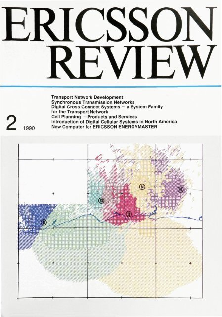
ERICSSON REVIEWNumber 2 1990 Volume 67Responsible publisher GostaLindbergEditor GoranNorrmanEditorial staff MarttiSubscription PeterMayrViitaniemiSubscription one year $30Address S-126 25 Stockholm, SwedenPublished in Swedish, English, French and Spanish with four issues per yearCopyright Telefonaktiebolaget L M EricssonContents54 • <strong>Transport</strong> <strong>Network</strong> <strong>Development</strong>60 • Synchronous Transmission <strong>Network</strong>s72 • Digital Cross Connect Systems - a System Family forthe <strong>Transport</strong> <strong>Network</strong>84 • Cell Planning - Products and Services92 • Introduction of Digital Cellular Systems in North America100 • New Computer for ERICSSON ENERGYMASTERCoverA picture showing the radio wave coverage ofseveral cells in a mobile telephone system is veryuseful when analysing the performance of thesystem
<strong>Transport</strong> <strong>Network</strong> <strong>Development</strong>Johan Bergendahl and Sixten EkelundThe substantial growth of transmission networks during recent years is expectedto continue and even increase. Operation and maintenance costs rise steadilyand the increasing number of business customers make new demands. Thedesign of the transport network is of great strategic importance and providesample facilities for meeting new and different demands.The authors describe the changes and the possibilities offered through newsystem architectures.During the 1960s and 1970s <strong>com</strong>paniespurchased <strong>com</strong>puters, mainly for thepurpose of rationalization. The 1980ssaw the demand that <strong>com</strong>puters shouldbe able to <strong>com</strong>municate with each other,and they were often installed in orderto increase the <strong>com</strong>pany's <strong>com</strong>petitiveness,through shorter lead times inproduct development and faster andmore reliable transfer of information.tele<strong>com</strong>munication networksdigital <strong>com</strong>munication systemstele<strong>com</strong>munication network managementOrdinary telephony is still the primaryapplication for the tele<strong>com</strong>municationsnetwork. Telephony is one of the mostimportant means of <strong>com</strong>munication inour society. It has formed the basis forthe introduction of new, important <strong>com</strong>municationsfacilities, for exampletransmission of documents via telefaxand data <strong>com</strong>munication via modems.Quality and network availability have alwayshad high priority but the great importanceof tele<strong>com</strong>munications in present-daysociety requires that theseproperties are implemented and safeguardedto an even greater extent.However, the tele<strong>com</strong>munications networkis also used to meet the specific -and growing - needs of the businessworld. The industrial environmentthroughout the world is changing, andboth national and multinational <strong>com</strong>paniesare encountering new conditions.Many large enterprises buy up <strong>com</strong>petitorsor sign cooperation agreements,and an increasing number operate internationally.During the 1990s <strong>com</strong>puters will be<strong>com</strong>eessential to most activities and tothe survival of <strong>com</strong>panies. Communicationbetween <strong>com</strong>puters will be a must.These demands are made by businessesthat are be<strong>com</strong>ing more scattered geographicallyand more internationalized,and will thus also affect the needfor tele<strong>com</strong>munications.The changing conditions for <strong>com</strong>panies,such as greater <strong>com</strong>petition andmore frequent product substitution, willresult in new and more stringent demandson network operators. These demandsinclude:- short and dependable delivery timefor leased lines and other services- increased network availability- guaranteed and verified performance<strong>com</strong>petitive prices- internationalization of services.The current deregulation of public tele<strong>com</strong>municationsresults in new networkoperators entering the market. They canbe expected to offer services that meetthe requirements from more demandingbusiness customers. Public network operatorsmust strive for profitability in theFig. 1The controllable transport network constitutesthe foundation of the tele<strong>com</strong>munications network.It ensures efficient integration of the transportof different services - while at the same timeensuring high quality and availability. The operationsupport functions constitute the <strong>com</strong>mondenominator of the entire network' Switched lines' Leased lines
55JOHAN BERGENDAHLSIXTEN EKELUNDEricsson Tele<strong>com</strong> ABincreasing <strong>com</strong>petition and must thereforeseek solutions that reduce costsand generate more revenue. The transportnetwork, fig. 1, is greatly affectedby the new demands and constitutes thebasis for an efficient tele<strong>com</strong>municationsnetwork.More efficient transportnetwork<strong>Transport</strong> network management providesgreat potential for reduction of operationand maintenance costs. With thecontinual growth of the networks, simplificationand automatization are be<strong>com</strong>ingincreasingly urgent matters.Measures that have a considerable effecton costs are:- rearrangement of routes- measurement of service performance- fault tracing- restoration of traffic after failures- planning of circuits.Rearrangement of routesRoutes in the existing network are alwaysrearranged when new routes are tobe installed. Users increasingly demandshorter delivery times, as well as shortconnection times, which makes rearrangementof routes a very demandingtask for the network operator.Measurement of service performancePerformance monitoring, which gives astatistical picture of the operation of thenetwork and an early indication of potentialproblems, will be<strong>com</strong>e more important.A change can already be seen in thatcustomersdemand highersignal qualityand expect it to be provided. Most likelythey will also demand guarantees andverification of the improved quality.Fault tracingDown time during failures must be minimizedin order to maintain high networkavailability. Business customers willsimply not accept loss of their strategicallyimportant means of tele<strong>com</strong>munication.Restoration of trafficSpeed is essential when a route hasbeen cut. Hitherto, high-priority traffichas been restored by means of quickmanual action in a chain of <strong>com</strong>plexcross connection frames.In future, the amount of high-prioritytraffic will grow as the number of connectionsbetween <strong>com</strong>puters increases.It will be difficult or even impossible torestore traffic manually and keep thedown time at an acceptable level Suchavailability issues will be of major importancein network operators' <strong>com</strong>petitionfor customers.A break in a large route will of coursealso mean a considerable loss of revenuefor the network operator.Planning of circuitsWith demands for many new connections,short connection times and shortdelivery times the costs will increasedramatically - if the demands are to bemet - unless better supporting technologybe<strong>com</strong>es available.A <strong>com</strong>petitive networkThe bit transfer cost is being successivelyreduced. The parallel trend of customersrequiring more capacity meansthat network operators' revenues aregrowing steadily. This situation will turninto a <strong>com</strong>petitive one, through the ongoingderegulation. <strong>Network</strong> operatorswill be faced with the choice of loweringtheir prices or else run the risk of losingcustomers to their <strong>com</strong>petitors.Fig. 2Tele<strong>com</strong>munications are assuming greaterstrategic importance to business customersThe main objective will be to retain existingcustomers by providing existingservices. If the operator is successful inthis respect his <strong>com</strong>petitiveness is prob-
56ably sufficient to attract new customerswith greater needs of <strong>com</strong>munications.Retaining customer relationships oflong standing and attracting new customersis a prerequisite for long-termprofitability. Competitive strength is thekeyword for network operators of thefuture.Some very important issues can be defined.A network operator must:- be <strong>com</strong>petitive by meeting the needsof business subscribers better thanthe <strong>com</strong>petitors- reduce operation and maintenancecosts and utilize the spare capacity inthe network- be able to meet demands for new servicesand functions- differentiate into classes of serviceperformance.CompetitivenessWhen operators introduce softwarebasedtechnology to implement networkfunctions, they invest in a tool thatmust be able to cope with a situationcharacterized by change and <strong>com</strong>petition.The technology should enablethem to create their own applications byadding features to the original or improvedplatform for control and supervisionof the network.A creative network operator can benefitfrom this adaptability - which shouldalso be reflected in the network elements- by being able to distribute hisown applications in the transport network.This is one way to achieve <strong>com</strong>petitivestrength based on a standardplatform.Utilization of available capacityExisting networks are so <strong>com</strong>plex thattheir full capacity cannot be made available(normally only 50 % of the possibletraffic capacity is used). Much is to begained from a higher degree of networkutilization, which probably could be increasedto 70% through the introduc-Fig. 3Software-controlled network <strong>com</strong>ponents minimizethe need for manual action in the field
57Fig. 4One of Ericsson's demonstration rooms, fortransport network functionstion of new technology. It would imply aconsiderable increase of network capacitywithout the need for installingnew cables. The cable cost is up to 80 %of the total investment in the network.In addition to the unused capacity thereis a planned spare capacity in the networkwhich may often be as large as theordinary transport capacity. Theplanned spare capacity could possiblybe reduced or used for low-priority traffic.The low-priority traffic would thenbe cut off if its route is used to reroutenormal or high-priority traffic.New servicesThe success of network operators isgreatly dependent on their ability tomeet the special requirements of businesscustomers, since this category accountsfor a large part of the revenueand continually increases its investmentin <strong>com</strong>munications.It must be possible to introduce new servicesof any kind quickly. A service isoften initially introduced with limitedfunctionality and then tested by specificusers.DifferentiationBusiness customers are be<strong>com</strong>ing increasinglydependent on their tele<strong>com</strong>munications,and availability is thus ofthe utmost importance. The growth indata traffic also results in more stringenttransmission quality requirements.The time end users accept for delivery ofa new connection or service be<strong>com</strong>esshorter and shorter, especially if theyhave access to alternatives, e.g. fromother network operators.The end users are <strong>com</strong>panies of varyingsize, represent different business areas,operate at different levels of technology,have different geographical distributionof their business etc. So, end users' willingnessto pay will obviously vary withthe importance they attach to their needof <strong>com</strong>munications in their operations.This presents an opportunity forthe networkoperator to offer different qualitylevels, delivery times etc. at differentprices.OpportunitiesThe transport network must be dynamicin order to be able to deal with thechanging requirements of the customers,the expected <strong>com</strong>petitive marketand the need for efficient operation. Operationand maintenance must also behandled with less manpower and expertise.Ericsson's solution to these problems isa transport network with software-controllednetwork elements. Operation issimplified and automated, and the needfor manual action in the field is reducedto a minimum.
58<strong>Transport</strong> network; basicprincipleChange, evolution and security are thekey parameters when planning a transportnetwork. In addition, operation andmaintenance costs must be minimized.If these requirements are to be met satisfactorilyit is necessary to have an integratedsolution for the whole transportnetwork, based on standardizedinterfaces.Ericsson is developing standard-basedmodular systems that can be adapted tomeet different requirements as regardsapplication, capacity etc. Control andsupervision can be either local or centralized.Existing plesiochronous systemscan be upgraded and integratedinto the overall transport network.The new system family for supplementingthe transport network consists of:FMAS Facility Management System,for control and supervisionDCCSDHDigital Cross Connect systemSynchronous Digital Hierarchy,a hierarchy of synchronoustransmission systems.DCC is Ericsson's product family namefor equipment that meets the requirementsmade by CCITT on SDXC (SynchronousDigital Cross Connect) systems.FMASFMAS is a system with <strong>com</strong>puterizedworkstations intended for administration,control and supervision of thetransport network and its services, suchas leased lines. FMAS has the flexibilityand modularity required to make it agood tool for the future transport networkwith its changing requirements.FMAS is designed to be able to controlnetwork elements, situated at differentnodes, from one or more hierarchicallyorganized operating centres. This hierarchymay <strong>com</strong>prise local as well asregional and national levels.FMAS is based on the TMOS platform,Ericsson's TELECOMMUNICATIONSMANAGEMENT AND OPERATIONSSUPPORT, which has been supplementedwith the FMAS applications program.FMAS can interwork with or incorporatesome or all other members of the TMOSfamily. 1 This increases the efficiency ofthe system and facilitates adaptation tofuture needs.Fig. 5A conceptual implementation of the new network
59DCCDigital cross connect systems representa new product family that provides networkoperators with equipment for networkprotection, including facilities forefficient control and utilization of existingnetwork capacity, which improvesthe possibilities of quickly arrangingleased lines with the desired capacity.DCC also makes it possible to increaseavailability through its ability to makeautomatic reroutings, forexample in thecase of breaks or other failures.The input to DCC consists of digital signals,which are cross connected in anon-blocking switch that forms part ofDCC. The cross connection can be controlledeither locally or from a centralnode via FMAS. The hierarchic level atwhich the signals are cross connectedcan be the same as or lower than that ofthe terminated signals. 2SDHThe optical synchronous transmissionsystems represent another new productfamily for the transport network, basedon the synchronous digital hierarchy(SDH) recently standardized by CCITT. 3These systems can be used for transportof present-day plesiochronous signals,such as 2 and 140 Mbit/s, as well as futurebroadband signals.SDH is an international standard whichwill eventually include the optical interfacesas well. Systems with line bit ratesfrom 155 Mbit/s up to 2.5 Gbit/s are beingdeveloped to ac<strong>com</strong>modate applicationswith different capacity requirements.The synchronous structure makes itpossible to branch, add and throughconnectcapacity from the line, whichcan itself be terminated or through-connected.This means that new, cost-efficientnetwork configurations, for examplefibre loops, can be implemented.The modular elements can be used indifferent configurations in both SDHand DCC systems.The controlled synchronoustransmission networkA <strong>com</strong>plete transport network is neededto ensure optimum function and flexibility.Fig. 5 shows a conceptual implementationof a future transport network,which includes multiplexers with facilitiesfor branching of channels (ADM,Add-Drop Multiplexers), synchronoustransmission systems (SDH), digitalcross connect systems (DCC) and theoperating system (FMAS) at the local,regional and national levels.The <strong>com</strong>bination of FMAS, DCC andSDH gives a <strong>com</strong>plete network solutionthat makes it possible to develop existingtransmission networks into a <strong>com</strong>prehensive,controlled synchronoustransmission network that guaranteesflexibility, availability, high quality andcost effectiveness.These basic elements enable the networkoperator to cope with the changingmarket situation and the rapidgrowth of the network. The need to introducethe new elements into the networkmay seem urgent, but it is essentialto have a long-term strategy that alsoincludes integration of the existing systems.References1. Ljungblom, F.: A Service ManagementSystem for the Intelligent <strong>Network</strong>.Ericsson Review 67 (1990):1, pp. 32-41.2. Andersson, J.-O.: Digital Cross ConnectSystems - a System Family forthe <strong>Transport</strong> <strong>Network</strong>. EricssonReview 67(1990):2, pp. 72-83.3. Breuer, H.-J. and Hellstrom. B.: SynchronousTransmission <strong>Network</strong>.Ericsson Review 67 (1990):2, pp. 60-71.
Synchronous Transmission <strong>Network</strong>sHans-Jurgen Breuer and Bengt HellstromIn 1988, CCITT standardized a new method for multiplexing digital signals. Thenew standard, called the Synchronous Digital Hierarchy (SDH), facilitates moreefficient transport of signals in future tele<strong>com</strong>munications networks.The authors describe the background and characteristics of the standard, someapplications and some new, flexible network <strong>com</strong>ponents.method of achieving the maximumtransmission capacity within the limitationsof digital technology. There is nostorage of bits; they are transmitted asthey arrive. However, the semiconductortechnology now available makes italmost as easy to multiplex tributarieswith eight bits at a time - an octet orbyte. This gives the tributaries a64 kbit/s structure.digital <strong>com</strong>munication systemssynchronisationtele<strong>com</strong>munication networkseconomicsBackground and drivingforcesIn traditional digital multiplexing, seeBox 1, a number of plesiochronous bitstreams, tributaries, are bit interleavedin several multiplexing steps. The tributarybit stream rate is then transmittedindividually - through the use of bit justificationin each multiplexing step -and can be recovered after transmission.Bit interleaving has been the bestThe introduction of digital telephoneexchangeshas resulted in integration ofdigital transmission and switching. A64 kbit/s infrastructure based on the interleavingof bytes has grown up. Thestructure is derived from the multiplexingstructure in 1.5 and 2 Mbit/s primarysystems. The position of each byte in theframe of the primary system identifies aspecific 64 kbit/s channel. In principle,all frames sent from a digital exchangeare synchronous; not plesiochronous.Box 1PLESIOCHRONOUS DIGITAL HIERARCHYFairly recently, Tele<strong>com</strong>munications Administrationsstarted to supplement the analog transmissionsystems with digital systems. Speechand data were encoded digitally by means ofPCM and multiplexed. This provided uniformtechnology for transmission of many channelson a line pair. The multiplexing, at first 24 channelsin the US, later 30 channels in Europe,reflects the technical development in the semiconductorfield. These channel numbers werefixed in regional standards for basic PCM systems.With the further development of semiconductortechnology a growing number of basicsystems have been assembled in higherordertransmission systems with successivelyhigher hierarchic levels, which in their turn havebeen standardized.The demands for synchronization in these systemswere limited to ensuring that the sametiming was used at both ends of a transmissionlink, a prerequisite for correct demultiplexingand decoding. At the introduction of PCM thetele<strong>com</strong>munications network contained primarilyanalog exchanges, so no digital interconnectionfacilities were needed away fromthe transmission links. Economic restraints ledto fairly modest requirements regarding the absolutetolerance for the timing. Timing transparencyin higher-order multiplexing was providedby a sophisticated method with bit justificationin the case of long delays in the in<strong>com</strong>ing bitstreams and verification of the correctness ofeach bit in the outgoing bit stream.Thus, these digital systems handle plesiochronoustributaries (see footnote) and the resultantdigital hierarchy has therefore recently, andquite correctly, been called PlesiochronousDigital Hierarchy (PDH). Its characteristics canbe summarized as follows:- There are two hierarchies. The one based onthe bit rate 1,544 kbit/s is used in North Americaand Japan. The other is based on 2,048kbit/sand is used in the rest of the world. (SeeTable 1.) The level 139,264 kbit/s occurs inboth hierarchies but only the bit rate is thesame; the tributaries have different <strong>com</strong>positions.Certain standards that specify how thehierarchies are to interwork have beenagreed by CCITT- If the line capacity of the basic systems isinsufficient it is necessary to use higher levelsin the hierarchy. Each level requires multiplexingof the signal, with bit interleaving ofthe tributaries and justification- Already at the first justification the possibilityof easily recovering individual 64 kbit/s channelsis lost. Thus all intermediate levels mustbe processed when demultiplexing from ahigh level to a lower. This is a disadvantage insome applications. It is sometimes difficult toutilize the existing transport capacity; for example,it may be possible to use only a smallfraction of the capacity in a 140 Mbit's system- 2,000 channels- No standard has been set for line equipment,which can therefore be designed to be specificto each manufacturer. This applies to thelogic and physical shape of the line signal aswell as to the operation and maintenancefunctions.Footnote: Plesiochronous signals have thesame nominal bit rate. The permissible deviationfrom the nominal rate is specified.However, hitherto higher-order structureshave been formed by plesiochronousmultiplexing. This method is notappropriate in an integrated digital networkfor the following reasons:- justification, which is used to adaptthe timing of the different tributaries,is unnecessary since all 64 kbit/schannels from an exchange have thesame 125 /J.S time base in the network- the justification process makes it impossibleto identify a channel directlyin a higher-order frame by means ofthe position of a byte or a sequence ofbytes. 64 kbit/s channels in a routebetween two local exchanges cannotbe branched until the higher-orderstructure has been demultiplexed toprimary level. There is a need forbranching, e.g. of a route or a channelused for operation and maintenance- channels formed by a sequence of nbytes within a frame (nx64 kbit/s) andwhich cannot be ac<strong>com</strong>modated atthe primary multiplex level (1.5 or2 Mbit/s) cannot be handled by thenetwork- maintenance information is not associatedwith whole routes; only withindividual transmission links. Themaintenance procedure for wholeroutes will then be <strong>com</strong>plicated. Theexisting integrated digital networksupports data services based on64 kbit/s channels within the frame-
61work of ISDN, but if each traffic routewere associated with a maintenancechannel the data services would havehigher availability and transmissionquality.Synchronous DigitalHierarchyCCITT has prepared an alternative multiplexingmethod based on synchronoustributaries with a byte structure,the Synchronous Digital Hierarchy(SDH).'- 3 The byte structure in SDH supportsthe 64 kbit/s structure, which isneeded for an ISDN (Integrated ServicesDigital <strong>Network</strong>). In addition, the SDHstandard has been designed so thatgroups <strong>com</strong>prising up to some thousand64 kbit/s channels can be handledas a route or as a broadband channel fortele<strong>com</strong>munications services requiringhigh capacity. Routes and broadbandchannels can be mixed.Within SDH the transmission capacitycan be selected in modular steps, givingthe necessary flexibility in view of theneed to be able to branch routes havingdifferent capacity. The routes can be associatedwith channels for maintenanceinformation. SDH is specified by CCITTin Re<strong>com</strong>mendation G.707 (the hierarchiclevels), G.708 (the SDH interfacetowards the tele<strong>com</strong>munications network)and G.709 (multiplexing structureand overhead information).A <strong>com</strong>parison between SDH and FDM(Frequency Division Multiplex) is interesting.The payload with the associatedoperation and maintenance informationthat has been put in a container (this andother SDH concepts are explained inBox 2) can in SDH be kept together oververy long distances through the network,a path. If the payload is transferredto a higher multiplexing level overa part of the transmission route, the pathwill still be preserved - unlike PCM itdoes not have to be restructured whenthe tributary configuration is changedA path in SDH can be <strong>com</strong>pared with agroup in FDM where pilot monitoringhas been replaced by path overhead.SDH has two major advantages <strong>com</strong>paredwith FDM: voice, picture and datacan all be transmitted in digital form andthere is much more room for operationand maintenance information. In thetime domain, SDH is a worthy successorto FDM.Layered transport modelTraffic routes must be available betweenarbitrary points in a network. Ateach point where a route starts it mustbe possible to change the tributary configurationin at least one transmissionsystem.SDH has four multiplexing levels withdifferent capacities. The multiplexinglevels with the highest capacities areplaced in a transport layer, whose basicmodule has a capacity of 155.52 Mbit/s.This basic module is called STM-1 (Synchronous<strong>Transport</strong> Module). Tributariesmust be inserted into or droppedfrom an STM module via an AdministrativeUnit (AU). Different network operatorsprefer different capacity modulesfor the highest multiplexing level theywant to handle in their networks. AU3, atlevel 3, has a capacity of approximately50 Mbit/s and AU4, at level 4, approximately150 Mbit/s. AU3 is used primarilyin the US and AU4 in Europe. A transportlayer is provided for each link betweentwo nodes in the network. It has a capacitythat is a multiple of the 155.52 Mbit/sbasic module, which is the lowest transportrate in SDH.In North America the SONET systemhas-in addition to the SDH standard-alowest transport module with a capacityof 51.84 Mbit/s. Higher rates are in accordancewith the CCITT standard forSDH. In all layers the space for the payloadis associated with capacity for operationand maintenance functions forthe layer in question.Multiplexing levelsThe lowest multiplexing level is designedfor the connection of byte structuresthat correspond to the total payloadin a 1.5 or 2 Mbit/s primary multiplex,either as B-channels (64 kbit/s) ordigital channels with greater wordlength. The HO and H1 channels definedfor ISDN correspond to 6 and 24 or 3064 kbit/s channels respectively. The capacityof the level, including overhead,is 1.664 or 2.240 Mbit/s, which is thecapacity of the virtual containers VC11and VC12 respectively.
Fig. 2The synchronous hierarchy makes it possible torealize many new, flexible network elements.Different types of tributary can easily be <strong>com</strong>binedLTADMSDXCD1-D4Line TerminalAcid-Drop MultiplexerSynchronous Digital Cross Connect (DCC)systemPleslochronous tributariescan obtain its timing from a synchronous2 Mbit/s output signal from an exchangeor via a separate 2 MHz clocksignal, fig 1. When no reference clock isavailable, for example in a subscribernetwork, one node can be appointed amaster node, from which other nodesare synchronized by extracting the timingfrom the in<strong>com</strong>ing STM signal.Early point-to-point SDH applicationsdo not need an external reference forsynchronization. A local oscillator in theterminal equipment at one end can beappointed master, and other equipments- intermediate repeaters and terminalat the other end - are synchronizedwith the master.Flexible bearer servicesThe work on SDH coincides with twoimportant events:- digital cross connect equipment(SDXC, DCC) is introduced. 4 Controlledby <strong>com</strong>mands from a centralizedadministrative system (e.g.FMAS), this equipment can changethe network topology and the distributionof network capacity. In thisway the network can be rapidly adaptedto changing <strong>com</strong>municationneeds- there is a growing need for connectionsthat can meet the requirementof variable bandwidth for differentservices.Consideration is being paid to boththese factors in the work on SDH.Digital cross connect (SDXC) systemscan through-connect whole multiplexinglevels and these can thus be maintainedover long distances and throughseveral nodes. End-to-end maintenanceis now feasible since the maintenancechannels are associated with the routesthat form part of a level. The levels canbe extended into the subscriber network,and the user can quickly have accessto leased lines with varying capacity.Automatic routines that use theoperations support system of the networkmake it possible for a subscriber toset up a leased line with the desired capacityhimself. In the near future, SDHand SDXC will be used to interconnectlocal area networks, via the public network,in a physical infrastructure thatsupports protocols in <strong>com</strong>ing standardsfor Metropolitan Area <strong>Network</strong>s (MAN).SDH also offers its payload capacity inVC4 for an individual bit stream to anend user, together with capacity formaintenance functions, fig. D, box 2.This facility is very important for thetransmission of high-speed signalsfromasynchronous terminals that need differentbandwidths for different services.The information is transmitted in theform of cells in Asynchronous TransferMode (ATM) in accordance with theplans for broadband ISDN (B-ISDN).SDH has been chosen as one structurefor the user interface in B-ISDN. Eachconnection has unique address informationin the cell header, and many connectionscan thus exist simultaneously.For each connection the cells can betransmitted irregularly, which amountsto varying instantaneous bandwidth.The maximum VC4 capacity is 44.15cells during a 125-microsecond period.It can be used for some ten connectionswith a few cells or a few connectionswith some ten cells, or varying numbersof types between these two extremes.The bit stream in VC4 must be kept constant.This means that idle cells must beinserted when connections exist but nocells are transmitted, or when no connectionsexist. These idle cells are insertedby the subscriber network in thedirection towards the public networkand by the local node in the other direction.SDH timing in subscriber networksis always obtained from the local node.The SDH frame can also be equippedwith a pointer that indicates the cellE
Tributary assemblies Internal interface Section assemblies 65A line terminal with optical tributariescan be used to build up three-shapednetworks, which may be of particularinterest for local networks, fig. 4. LTequipment can be installed on its own ortogether with a remote subscriberswitch. In the junction network, wherethe need for capacity and flexibility isgreater, a DCC would be chosen for anode rather than a <strong>com</strong>bination of LTunitsFig. 5System <strong>com</strong>ponents in Ericsson's family of SDMproducts. Tributary and section assemblies canbe <strong>com</strong>bined to form different network <strong>com</strong>ponents.The assemblies can be used in stand-alonetransmission systems (MUX LT, ADM) as well asin DCCFig. 6Ericsson's SDH systems can be supervised andcontrolled either from a central operating systemor from a local terminal. <strong>Network</strong> elements can becontrolled remotely via the data channels in theSDH frameFMASOSMONEQFacility Management SystemOperating SystemMediation Device<strong>Network</strong> ElementSerial maintenance interface in accordance withCCITT Rec. G.773signals to be switched are synchronous2 Mbit/s signals. Plesiochronousstreams are synchronized through bitjustification of the 2 Mbit/s signals, butby using STM-1 as the connection signalinstead of a plesiochronous 140 Mbit/ssignal it is possible to switch synchronous2 Mbit/s containers (VC 12) direct,in which case no justification is needed.DCC with a mix of plesiochronous andsynchronous ports can form a bridgebetween synchronous and plesiochronousparts of the network.The use of controllable cross connectsystems to increase flexibility is also anattractive solution for smaller networkelements, such as LT and ADM. In suchcases it may be difficult to define theboundaries between ADM and DCC andbetween LT and DCC respectively. Bothfacilitate similar functions, such as sortingand packing traffic. A DCC normallyhas greater capacity and flexibility, andan ADM can thus be considered a smallDCC, or a DCC a large ADM. The needfor capacity and flexibility in differentparts of the network then decides which<strong>com</strong>ponent should be used.<strong>Network</strong> structuresThe network <strong>com</strong>ponents describedabove can be used to build differenttypes of network and network structure.For example, an ADM can be used tocreate bus, tree and ring structures,fig. 3. Ring networks are most suitablewhen very high availability is required.In the case of a cable break the trafficcan automatically be rerouted in theother direction around the ring. Starshapedstructures often give greaterflexibility in that the capacity of a nodecan be increased without affectingequipment in other nodes.A system familyEricsson is developing a new family ofindependent transmission systems,based on the SDH standard, as part of a<strong>com</strong>plete transport network solution.Fig. 5 lists the units in the family. Thereare three main types of system-STM-1,STM-4 and STM-16-for the bit rates155, 622 and 2,488 Mbit/s respectively.Different types of tributary assembly,plesiochronous and synchronous, canbe connected to the section assembliesin different configurations.The systems all have a high degree ofmodularity. The same unit, a printedboard assembly, can be used in manydifferent applications, for example indifferent network elements - MUX/LT,ADM, intermediate repeaters - and indifferent physical network structures -point-to-point, tree, ring. The section assembliescan also be used as tributaryassemblies. All these factors contributeto more efficient network operation.Furthermore, the internal interfaces betweensection assemblies and tributaryassemblies are identical to the deviceinterfaces in DCC, and thus the sameassemblies can be used for SDH andDCC products. This contributes to moreefficient handling and also ensures easyintegration of optical line interfaces intoDCC.The SDH systems have extensive functionsfor supervision and control ofequipment and transmitted traffic.Functions for fault management, performancemanagement and configurationmanagement are based on the TMNre<strong>com</strong>mendations by CCITT. 5 Like DCC,the SDH systems have a Q interface forcentral maintenance using Ericsson'soperations support system FMAS (FacilityManagement System). Alternatively
66local control can be used. The internaldata channels in the SDH frame can beused for remote control of network <strong>com</strong>ponents,e.g. in subscriber networks,fig-6.Another feature of the SDH products isthat they can easily be modified for futurechanges in the network. As the trafficgrows, the system capacity can easilybe increased from STM-1 to STM-4 orfrom STM-4 to STM-16 with a minimumof hardware replacement. The availabilitycan be increased by adding functionsfor automatic protection switching.The first SDH systems to be developedare being optimized for transport of plesiochronoussignals, 2 Mbit/s and140 Mbit/s. The multiplexer and line terminalfunctions are integrated, whichgives cost-efficient units. At a slightlylater stage, with a more widespread synchronousnetwork, line equipment withsynchronous tributary assemblies canbe expected to be<strong>com</strong>e more <strong>com</strong>mon.MigrationThe synchronous transmission systemscan be introduced into various parts ofthe tele<strong>com</strong>munications network in anatural way. Fig. 7 shows an example ofpossible initial applications. There aretwo main types of system:- Point-to-point systems in metropolitanand long-distance networks- More or less expanded systems forsubscriber networks.In most metropolitan and long-distancenetworks there is a well built-out plesiochronousoptical fibre network. Here,small islands of synchronous systems inthe form of point-to-point systems canbe introduced without disturbing theplesiochronous hierarchy or <strong>com</strong>plicatingthe administration of the networknoticeably. An STM-4 system that transmitsfour 140 Mbit/s streams fulfils exactlythe same function as a 565 Mbit/ssystem. 6 Systems with gigabit capacitywill be required in the long-distance net-Subscriber networkFig. 7Synchronous islands in an otherwise plesiochronoustransmission network are formed when thesynchronous systems are introduced. The firstsystems are expected to be point-to-point links inmetropolitan and long-distance networks, andmore expanded structures in subscriber networks
67work in the early or middle 1990s. Withsuch an increase in capacity an STM-16system with 140 Mbit/s ports might bean attractive choice.At present there are no or very few fibreopticcircuits in the subscriber network.It is therefore not necessary to take existingplesiochronous systems into considerationif the termination in the localexchange is made at the 2 Mbit/s level.This means that the opportunity - andperhaps also the incentive - to build upan efficient synchronous transport networkat an early stage is greater in thispart of the network.Fig. 8 shows a possible development towardsan integration of the plesiochronousand synchronous networks for alarge local exchange or <strong>com</strong>bined localand tandem exchange. Fig. 8a showsthe situation at an early stage, correspondingto that shown in fig. 7. Most ofthe transmission equipment is plesiochronous.Synchronous line systemsare terminated in traditional electricalinterfaces, preferably at 2 and140 Mbit/s.The manual digital distribution frames(DDF) and multiplexers are replaced bya synchronously based DCC 4/1, fig 8b.DCC can convert between the synchronousand plesiochronous hierarchy andthe two networks can thus be integrated.Synchronous optical line systemscan then be terminated more effectively,either viaan asynchronous, electrical oroptical STM-1 intra-office interface ordirectly in the DCC. The latter alternativeis more efficient, but initially many networkoperators will probably want tomanage and maintain the line systemsseparately. One requirement for integrationwill probably be that the optical in-Fig. 8A possible way of introducing synchronoustransmission systems in a large local exchangea Initially the multiplexing equipment is plesiochronous,and synchronous systems aremainly terminated in plesiochronous 2 and140 Mbit/s interfacesb The introduction of DCC 4/1 makes it possibleto integrate the synchronous and plesiochronousnetworks. Synchronous line systemscan then be terminated directly in DCC, whichdistributes the signals to other synchronousor plesiochronous lines or into the exchangeDFFPLDigital Distribution FrameRadio link
68terface, including the protocol for operationand maintenance channels, is fullystandardized so that flexibility betweendifferent nodes in the network is obtainedin future.In the long term synchronous interfacesmay be integrated into exchanges andremote subscriber switches. An STM-1interface instead of 2 Mbit/s would beeven more cost-efficient, especially ifthe 64 kbit/s channel could be mappeddirectly into the STM-1 frame. Thiswould also <strong>com</strong>plete the transition fromthe plesiochronous to the synchronoushierarchy.Economic aspectsA fully built-out synchronous networkcould give great cost reductions. Thereasons are that- operation and maintenance costs arereduced because of added facilitiesfor diagnostics and internal <strong>com</strong>municationin the systems- more extensive standardization givesbetter <strong>com</strong>patibility between differentequipments- the flexible frame structure results ina future-proof solution, with the possibilityof transporting new signalsand services, and high potential forcapacity upgrading- the STM-1 interface can be directlyintegrated into switches.It may be necessary to have to accept aslightly higher cost for the administrationof the network during a transitionperiod, with mixed synchronous andplesiochronous equipment, in order toachieve long-term cost reductions.SummaryCCITT has <strong>com</strong>pleted the first stage inthe standardization of a new digital synchronoustransmission hierarchy. Theflexible frame structure of the hierarchyensures that both synchronous and plesiochronoussignals can be transmitted,and it has ample facilities for operationand maintenance information, e.g. fordiagnostics and internal <strong>com</strong>munication.The optical interfaces of the equipmentwill be standardized, which givesbetter <strong>com</strong>patibility.The synchronous structure makes iteasy to recover tributaries down to the64 kbit/s level. It also facilitates mixingof signals, both electrical and optical, ina line terminal. Flexible network elements,such as add-drop multiplexers,make for more efficient networks. Thehierarchy is also very suitable for digitalcross connect systems, whether separateor integrated into the line equipment.Equipment for the new hierarchycan preferably be installed in today'snetworks, both as point-to-point linestogether with plesiochronous equipmentand as more independent islandsin the subscriber network.Ericsson is developing a family of newtransmission systems based on the SDHstandard. The systems are characterizedby high functionality and modularityand constitute, together with DCCand FMAS management systems, a<strong>com</strong>plete solution for the transport networksof the 90s. 7
Table 1Bit rates for the PDH signalsPDHlevel01234Bit rate in the two hierarchies (kbit/s)basicallybasically1,544 kbit/s 2,048 kbit/s641,5446,31232,064 44,73697,728 139,264PDH: Plesiochronous Digital HierarchyTable 2642,0488,44834,368139,264Bit rates for the SDH signals at different multiplexinglevels, kbit/sLevel1 VC11 1,6642 VC2 6,8483 VC3 48,9604 VC4 150,336SDH:VC:Table 3SDH levelsLevel1416VC12 2,240Synchronous Digital HierarchyVirtual ContainerDesignationSTM-1STM-4STM-16Bit rateSTM: Synchronous <strong>Transport</strong> Modules155,520 kbit/s622,080 kbit/s2,488,320 kbit/sBox 2SYNCHRONOUS DIGITAL HIERARCHYCCITT has standardized a synchronous digitalhierarchy for the transport network, SDH. Datastreams with different capacity - from 1.544 to139.264 Mbit/s - are "packed" in containers ofstandardized size, capacity. To each containeris added the necessary system information(overhead). The unit thus formed is called aVirtual Container (VC). Several small VCs canbe packed into a larger; they are multiplexed atone of the four modular hierarchic multiplexinglevels that form part of SDH. The multiplexingprocess consists in interleaving bytes from thedifferent tributaries, VC. In this process, overheadis again added to the VCs being multiplexed.VCs from one of the two highest multiplexinglevels, usually the forth, are givenadditional overhead and placed in a transportlayer having a bit rate of 155.52 Mbit/s and designatedSynchronous <strong>Transport</strong> Module, level 1(STM-1). 155.52 Mbit/s is the lowest bit rate usedon the transmission links.BUILDING BLOCKSTributaries are placed in STM-1 in a number ofsteps via the following building blocks (cf.fig. C).Container, CC consists of a tributary whose rate, whennecessary, is equalized so that it can besynchronized with STM-1. C can also be afuture synchronous broadband signalVirtual Container, VCVC consists of a C supplemented with pathoverhead (see below) or a group of TUGsplus path overheadTributary Unit, TU, and Administrative Unit, AUBoth consist of a VC with a payload pointer(see below) added. The only difference betweenTU and AU is that the former is aframe-internal unit, which can be transferredto another STM-1 only via a higherorder AUTributary Unit Group, TUGTUG is a group of a number of identical TUsAdministrative Unit Group, AUGAUG is a group of a number of identical AUsSynchronous <strong>Transport</strong> Module, STMSTM is an AU with added section overhead(see below)DESIGNATIONSContainers and Virtual Containers are designatedCIJ and VCIJ respectively. I indicates themultiplexing level to which a C or VC belongs,1-4. For J, 1 means that the C or VC has thelowest bit rate at the level in question; 2 indicatesthe next higher bit rate at the level. J isomitted if there is only one bit rate at the level.PATH and SECTIONA transmission route limited by two line terminalsis called a section. The signal is carriedover the section by a synchronous transportmodule (STM) at a rate of 155 Mbit/s or multiplesof this rate.The information carried by an STM consists oftributaries. The structure is hierarchic. A groupof tributaries at the level immediately below asection a is called a path; it consists of one or anumber of traffic routes. A path can be throughconnectedfrom one section to another withouthaving to be unpacked, fig. A.PATH and SECTION OVERHEADMany bytes in STM-1 are reserved for systeminformation, called overhead. As has alreadybeen indicated, certain of these bytes are associatedwith a certain VC, whereas others are<strong>com</strong>mon to a whole transport section, STM. Atthe VC level, the system information is calledpath overhead (POH) and at the STM level sectionoverhead (SOH).The basic principle is that POH is handled onlyby equipment with plesiochronous tributary interfacesor by SDXC (synchronous digital crossconnect) equipment that terminates the correspondingVCs. All information in a path is kepttogether during the whole of its transferthrough the synchronous transport network.POH is required only when a path has passed allsections and is to be unpacked, into channels orchannel groups.SOH must be handled by all line terminal equipmentsince it contains information needed formaintenance of the section with which the SOHis associated.A path can carry several routes, fig. A. A routeand a path are often of the same length, but theroute may be transported over more than oneFig. AA number of circuits between local exchanges Aand D constitute a route. The corresponding64 kbit/s channels are placed in a container of asuitable size. The container together with the pathoverhead form a virtual container that is transportedvia a path. After further multiplexing thepath is placed in a transport layer, called a section.A path is kept together during the transport.Route AD is semi-permanently through-connectedby transit exchange B. Node C consists of synchronousdigital cross connection equipment. Itcan through-connect path BD from section BC tosection CD without unpacking the virtual container.A route and a path are often of the samelength, but when a route is through-connected bya transit exchange as shown here, the route istaken via more than one path
Fig. BTributaries from the plesiochronous and synchronousmultiplexing hierarchies can be <strong>com</strong>bined.Plesiochronous multiplexing layers can beplaced in the corresponding synchronous container(CI). The virtual container (VCI) is formedby adding the associated POHM MappingPOH Path OverheadSOH Section OverheadSTM-1 Synchronous <strong>Transport</strong> Module, level 1STM-N Synchronous <strong>Transport</strong> Module, level NFig. CThe synchronous multiplexing structureMapping means that a tributary is placed directlyin a container, without any interleavingPOHpath. In the latter case, tig. A, the route is semipermanentlythrough-connected by an exchange.When a path extends over several sections it isconnected from one section to another by synchronousdigital cross connect equipment(SDXC) or an add-drop multiplexer (ADM).POH contains information for error detection,fault and alarm indication from the far end,identification of the far end, and a <strong>com</strong>municationchannel. SOH contains, in addition toinformation like that in POH, a frame synchronizationword for the STM frame (see below) anddata channels for operation and maintenanceinformation. SOH also contains a number ofbytes which are at the network operators' disposal.POINTERIn principle, all nodes in a network are synchronizedby the signal from a very stable clockthat is distributed to all of them. Problemswould arise if synchronism was lost somewherein the network, and payload pointers havetherefore been introduced. Each byte in an STMframe has a position number. The pointer containsthe number of the byte where the payloadstarts.If the clock that controls STM runs slightly slowerthan the clock that controls the packing ofthe payload somewhere else in the network, theSTM buffer will eventually overflow. A byte fromthe payload is then placed in the pointer spaceand the pointer value is reduced by one. If theclock ratio is the inverse, the STM buffer willeventually be emptied. Justification bits arethen placed in a byte in the payload and thepointer value is increased by one.The pointer is also used when the network issynchronized. When several STM-1, <strong>com</strong>ingfrom different directions, are to be multiplexedto a higher STM layer it is unlikely, because ofpropagation distortion, that they are in phasewhen they reach the line terminal. The tributariescan then be brought into phase by adjustmentof the pointer value in all STMs, withouthaving to use large buffers.Fig. B shows the multiplexing principle of theSDH hierarchy. Tributaries can be taken from alllevels in the plesiochronous hierarchy and"mapped" to the corresponding synchronouscontainer (CI). VCI is obtained by adding pathoverhead to CI. Fig. C shows how different VCscan be <strong>com</strong>bined and placed in the STM frame;the multiplexing structure. All system information,SOH, is also placed in the STM frame. If
Fig. DFormat of the STM-1 frameThe STM-1 frame consists of 9x270 bytes. Theframe length is 125 Ms, and hence the bit rate is155.52 Mbit/s. It consists of a VC4 with sectionoverhead and a pointer. The payload in VC4 canconsist of either synchronous multiplex structuresin accordance with CCITT Re<strong>com</strong>mendationG.709 or a continuous stream of ATM cells. In thisexample the synchronous payload consists ofthree TU3, each of which contains one VC3higher capacity than 155.52 Mbit/s is required, anumber of 155.52 Mbit/s streams are byte interleavedand placed in a signal at a higher level.This multiplexing does not require any informationin addition to what is provided in the 155.52Mbit/s frame, since all tributaries are frame andbit synchronized. Higher levels can thus be synchronizedby means of frame synchronizationwords from the lower levels.Fig. C shows the multiplexing structure of thesynchronous hierarchy. Reading the figurefrom right to left, as indicated by the arrows,shows how low-capacity units can be <strong>com</strong>binedinto units with higher capacity. The rectanglescorrespond to the building blocks that form theSTM frame. The arrows show that buildingblocks on the right can make up building blockson the left, and x indicates how many of thesmaller blocks are needed. The structure wasaccepted by CCITT in May 1990 and deviatesslightly from that originally proposed in Re<strong>com</strong>mendationG.709.Fig. D shows an example of the structure of theSTM-1 frame. The frame has a 125 ,as time baseand contains 9x270 bytes. The bit rate is 155.52Mbit/s. An STM-1 usually consists of a VC4 supplementedwith SOH and a pointer. VC4 consistsof payload and POH. The structure of thepayload is illustrated by two examples. In one itconsists of three VC3s, each <strong>com</strong>prising one C3and POH. In the other example the payload consistsof a continuous stream of ATM (AsynchronousTransfer Mode) cells.Table 1 shows the standardized bit rates for theplesiochronous hierarchy.Table 2 gives the standardized bit rates for allVCs in the SDH hierarchy.Table 3 shows the most <strong>com</strong>mon STM levels.References1. CCITT Rec. G.707 Synchronous DigitalHierarchy Bit Rates.2. CCITT Rec. G.708 <strong>Network</strong> Node Interfacefor the Synchronous DigitalHierarchy.3. CCITT Rec. G.709 Synchronous MultiplexingStructure.4. Andersson, J.-O..Digital Cross ConnectSystems - a System Family forthe <strong>Transport</strong> <strong>Network</strong>. EricssonReview 6Y(1990):2, pp. 72-83.5. Widl, W.: Standardization of Tele<strong>com</strong>municationManagement <strong>Network</strong>s.Ericsson Review 65 (1988):1, pp.17-23.6. Hansson, A.-K. and Linden, K.: OpticalFibre Line System for 4x140 Mbit/s, aNew 565 Mbit/s Application. EricssonReview 64 (1987):3, pp. 102-109.7. Bergendahl, J. and Ekelund, S.: <strong>Transport</strong><strong>Network</strong> <strong>Development</strong>. EricssonReview 67(1990):2, pp. 54-59.
Digital Cross Connect Systems -a System Family for the<strong>Transport</strong> <strong>Network</strong>Jan-Olof AnderssonDigital cross connect systems will be<strong>com</strong>e a very important system <strong>com</strong>ponent inthe tele<strong>com</strong>munications networks of the 90s. They enable network operators toadapt their networks to customers' requirements, provide high-quality networkservices and utilize the network resources in an effective and flexible manner.The author describes characteristics and applications of the digital cross connectsystems and discusses some implementation aspects.services quickly. It should be possible toadapt the network accordingly; quicklyand preferably without manual action.A central system that monitors the stateof all connections and which can controlequipment distributed throughoutthe network makes it possible to adaptthe configuration of the transport networkto any traffic situation.digital <strong>com</strong>munication systemssynchronisationtele<strong>com</strong>munication networkstele<strong>com</strong>munication network managementTo a network operator the tele<strong>com</strong>municationsnetwork represents an immenseinvestment and it is essential that its resourcesare used efficiently.The trend is towards networks beingused for an increasing number of subscriberservices. They also transmit differenttypes of information, not onlyspeech as they used to. The networkshould be able to handle different typesof information simultaneously and efficiently.Failures, such as cable breaks, occur.Sophisticated business subscriberswant to change their <strong>com</strong>municationsEricsson's product family of DigitalCross Connect systems, together withour Facility Management System(FMAS), meets the requirements specifiedhere. 1Digital cross connect system- basic functionsThe basic principles of digital cross connectsystems are most easily <strong>com</strong>prehendedby studying what functions theyperform and which equipment they canreplace.Fig. 1a shows the transmission of a largenumber of telephony channels, typicallyaround 2000, between exchanges viafibre or coaxial cables.High-speed routeFig. 1The basic functions of the DCC systemsa High-speed circuits are used for traffic betweendifferent nodesb Cables from the exchange terminals, eachcarrying traffic corresponding to 30 telephonychannels, are connected to a distributionframe (DDF), which is manually rearranged.Multiplexers are also connected to the DDF.They multiplex 30-channel groups into signalsfor the high-speed routes. Certain routes aretransited direct from an in<strong>com</strong>ing to anoutgoing multiplexer via the DDFThe DCC systems can be used to replace both themanual distribution frame and the multiplexers,which are integrated into the DCC systemDDFDCCMUXManual distribution frameDigital cross connect systemMultiplexer/demultiplexer
73Fig. 1b shows in greater detail how thejunction circuits are assembled. EachET (Exchange Terminal) output in anAXE 10 exchange is connected, via a cablefor 30 telephony channels, to amanual digital distribution frame (DDF),to which a number of multiplexers arealso connected. The multiplexers assemblea number of 30-channel circuitsinto one high-speed route, and vice versa.This reduces the number of cablesneeded between exchanges. By multiplexerin this context is meant a <strong>com</strong>binedmultiplexer/demultiplexer, sincethe circuits are bidirectional. Some ofthe cables to the manual DFF are bypassedthe AXE 10 exchange and connectedfrom one multiplexer directly toanother. They carry transit traffic.Digital cross connect systems can replaceboth the manual DDF and the multiplexers,but some of the system variantsdeveloped replace only the DDF.The systems consist of access units fortransmission signals and a switch thatperforms the switching functions.DCC is Ericsson's designation for productsthat are <strong>com</strong>patible with SDXC(Synchronous Digital Cross Connect) inthe SDH standard. 2 DCC systems acceptsynchronous signals in the SDH hierarchy(155 Mbit/s) and plesiochronoussignals in the CCITT hierarchies basedon 1.5 and 2 Mbit/s. With synchronous155 Mbit/s signals (STM-1) connected tothe DCC, the system can switch synchronoustributaries at 2 Mbit/s, for example.There is no need to go throughthe intermediate multiplexing levels between140 and 2 Mbit/s because anytributary can be identified by means ofits position in the STM frame.Each DCC system is provided with oneor several channels for supervision andcontrol. For example, reconfigurationsin the DCC switch can be ordered. Thenetwork operator can connect networkmanagement <strong>com</strong>puters etc. to thesechannels, and in this way exploit to thefull the flexibility and multitude of functionsof the DCC systems. Ericsson hasdeveloped its Facility Management System(FMAS) for this purpose. The FMAScan be used to control DCC systems atthe local, regional or national level.Ericsson Tele<strong>com</strong> is now developingthree different types of digital cross connectsystems: DCC 1/0, DCC 4/1 andDCC 4/4. The first digit denotes thehighest level of the in<strong>com</strong>ing datastreams, and the second digit denotesthe lowest level at which they can beswitched. Thus, a DCC 4/1 system canboth receive and switch data streams atlevels 1, 2, 3 and 4. The level concept fordifferent transmission hierarchies is explainedin reference 2, which also describesthe CCITT standard SynchronousDigital Hierarchy and otherproducts in the transport network family.DCC, a cornerstone in thetransport networkSince a tele<strong>com</strong>munications networkrepresents an enormous investment,the network operator wants to utilize itas efficiently as possible. It quite naturallybe<strong>com</strong>es a matter of cutting costsand increasing revenues. Thus the networkoperator seeks to reduce manpowerrequirements and the lifecycle cost ofthe equipment and at the same time improvethe availability and quality of thenetwork. These requirements result inthe introduction of:- more automatized systems- <strong>Network</strong> Management Systems forcentralized diagnostic and supervisionfacilities- network databases, capable of exchanginginformation- systems that increase the availabilityof the network.Applications of DCC systems include,fig. 2:- arranging leased and special circuits- operation and maintenance of thetransport network, including provisionof network protection- network administration.Combinations of these applications arealso possible.Leased linesIn spite of the continual modernizationof tele<strong>com</strong>munications networks it appearsthat the need for leased or privatelines is increasing, for example for64 kbit/s or 2 Mbit/s. This trend is particularlynoticeable in the US, where thereis talk of a T1 boom. (T1 is the designationfor 1.5 Mbit/s circuits.) Another
Fig. 2The DCC systems can be used in many differentapplications: to reroute traffic after cable breaks,to set up leased broadband circuits, to redirectthe traffic flow, and to improve the supervision ofthe tele<strong>com</strong>munications network. The DCCsystems can be controlled via the Facility ManagementSystem (FMAS)Fig. 3Alternative methods of protection switchinga The simple model network contains nodes A,B and C. Traffic between A and C and betweenB and C requires one carrier whereastwo are needed between A and Bb Protection switching system 1 :f is used. It isa prerequisite that the standby lines are runvia one of the other nodes. For example, thestandby line for A to C is taken via B. Thetotal number of standby lines is eightc The DCC system with its flexible switch arrayis used. Only five standby lines are needed.In both cases the number of standby lines ishigher than the number of carriers. Thereason is the size of the model networkchosen and the unbalanced traffic interestfactor that influences the need for DCCis that data networks are still separatefrom the public networks. Many networkoperators set up separate networks inorder to offer leased nx64 kbit/s lines.The DCC systems, mainly DCC 1/0 andDCC 4/1, are particularly suited to theseneeds.Operation and maintenance, networkprotectionProducts for transport networks, suchas DCC systems, can contribute greatlyto more efficient operation and maintenanceof the transport network. DCCsystems are placed in both large andsmall network nodes and can thus beused to collect operational data, whichis processed by centralized operatingsystems. In this way the network operatorcan have the state of the networkalmost continuously monitored. EricssonTele<strong>com</strong> has developed a family of<strong>com</strong>puterized systems for administrationand supervision of tele<strong>com</strong>municationsnetworks, TELECOMMUNICATIONS MANAGEMENT AND OPERATIONS SUPPORT (TMOS). The TMOSfamily includes FMAS, which is designedfor the transport network.An example of the use of DCC for networkoperation: A subscriber leases aline with a set transmission quality, e.g.an error rate of less than 10 7 . If the qualityof the circuit provided deteriorates,the network operator can - after analysisin FMAS - select another circuit thatmeets the requirement.The Synchronous Digital Hierarchy(SDH) will be introduced gradually, andthis will increase the available capacityfor transfer of operation and maintenanceinformation.A clear trend of growth in the number ofcircuit breaks has been noticed. Thereare several reasons: cables are increasinglyexposed to excavation damage,electronicequipment isdisabledand reconnectionsare made incorrectly. Theintroduction of glass fibre cables resultsin more traffic per cable, which meansthat a larger percentage of the total trafficis affected by a cable break. The financialadvantages of glass fibre cable
Fig. 5One way of providing network protection in anetwork with a large number of nodes equippedwith DCC is to divide the network into a numberof regions. The network within each region isdimensioned so that the traffic can be restored ifa failure occurs within the region. A superregionis arranged for the traffic between regions. Itincludes at least one DCC system from eachregion. The network in the superregion hassufficient standby capacity to restore the originaltraffic flow when a cable break occurs betweentwo regionsFig. 4Comparison between the standby capacityrequired with DCC systems and ProtectionSwitching System 1:1 used in a large network. Ifthe number of traffic-carrying lines is set to one,the length of standby lines required with DCCsystems amounts to 0.8. With Protection SwitchingSystem 1:1 the total length of standby linesrequired is twice that of the traffic-carrying linesRelative length of linein the networkare undisputable, and thus strategiesfor network protection be<strong>com</strong>e moreimportant.There are different ways of preservingthe transmission capabilities of the networkduring circuit breaks. 140 Mbit/ssignals can be protected by the followingsystems: Protection switching system1:1 or 1 :N or DCC 4/4, fig. 3, or any<strong>com</strong>bination of these. Protectionswitching systems replace a circuit betweentwo nodes. The 1:1 system has astandby line for every line that carriestraffic, whereas in the 1:N system onestandby line is shared by N lines carryingtraffic. The standby line should bephysically separated from the lines carryingtraffic. When the protectionswitching system detects the absence ofa signal on a traffic-carrying line, thesystem immediately switches over to thestandby line at both ends of the section.This eliminates the consequences of thefault. One advantage of protectionswitching systems is the fast changeover.The disadvantage is the relativelylarge number of standby lines needed -particularly for the 1:1 system, which isthe most <strong>com</strong>mon type.The DCC 4/4 system could be used as aprotection switching system, but thechangeover is somewhat slower. Thegreat advantage of DCC 4/4 is that thechangeover can be controlled end-toend- i.e. from the originating to theterminating node - which means thatthe number of standby lines can be reducedconsiderably. FMAS analyses thetraffic pattern between different nodesand uses the flexible switching networkin the DCC systems to make the appropriatechanges.<strong>Network</strong> analyses indicate that protectionswitching systems need 23 times asmany standby lines as the DCC 4/4 system.The difference be<strong>com</strong>es larger withthe size of the network, fig. 4.The type of protection rerouting controlshould be different depending on thesize of the network. A network <strong>com</strong>prising50,100 nodes with 5,000-10,000 terminationpoints can be handled by oneFMAS. <strong>Network</strong>s <strong>com</strong>prising up to 1,000nodes should be divided into a numberof regions; each region being controlledby one FMAS. Such division is appropriatebecause the analysis of possiblestandby routes be<strong>com</strong>es more <strong>com</strong>plicatedand time-consuming the largerthe network. <strong>Network</strong> operators normallyrequire that approximately 100 circuitsat 140 Mbit/s should be switchedand carrying traffic 510 seconds after acable break.Regions can be arranged in differentways. One example is shown in fig. 5. Aregion is formed by adjacent nodes. It isdimensioned with full standby, i.e. if acable break occurs it is possible to setup standby routes within the region.One or a few nodes in each region areused for <strong>com</strong>munication with other regions.In this way a superregion isformed. The latter, too, is dimensionedwith a full standby network, whichmeans that a cable break within the superregioncan also be handled there.Each region, including the superregion,is equipped with its own network controlsystem, so that failures can be clearedquickly. Administratively, the controlsystem of the superregion is superior tothose of the regions in order to ensurethe consistency of the information to thenetwork operator.The structure can be further elaborated,with sub-regions, sub-subregionsetc, ifthe number of nodes in a region growstoo large.<strong>Network</strong> administration<strong>Network</strong> administration, i.e. the plannedmanagement of the tele<strong>com</strong>municationsnetwork, covers a wide range ofapplications. Its objectives include reducingthe cost of recurring tasks andbeing able to quickly provide the customerswith the connections they request.The systems most suitable fornetwork administration purposes areDCC 4/1 and DCC 1/0, partly becausethese systems include multiplexer functions.Most tele<strong>com</strong>munications networkshave an annual growth of 10-20%,which means that 15-20 % of a DDF is
Fig. 6The sorting facilities of the digital cross connectsystems can be used for many purposes. A DCC,placed in a local exchange, can distribute trafficto the public tele<strong>com</strong>munications network, privatenetworks and data networks. When the broadbandnetwork is introduced, DC can be used toconnect users to the few, centralized broadbandexchanges that will be installed during the initialperiodAM Connection modulereconnected per month. A networknode can have a few thousand 2 Mbit/slines connected to its DDF. The cost ofeach reconnection is estimated at approximately1,000 USD. The potentialfor rationalization is obvious. Thescheduling time for carrying out and coordinatinga number of manual reconnectionsis 12 months, which meansthat the network has to have redundantcapacity and, hence, the degree of utilizationis low. There are networks inwhich, on average, only 20 of the 642 Mbit/s channels in a 140 Mbit/s signalcarry traffic, i.e. 70 % of the traffic-carryingpart is unused.Using DCC systems and FMAS enablesthe network operator to increase the degreeof network utilization considerably,and thereby its standby capacity.The existing network can then generatelarger revenue and its availability is improved.The introduction of these systemsalso benefits the subscribers becausethe network operator's schedulingtime is greatly reduced.The network operator can also use DCCsystems to separate different traffic categories.Forexample, a DCC placed in alocal exchange, fig. 6, can be used todistribute traffic to the public network,independent data networks, private networksand special networks, e.g. fortransmission of alarms.When broadband services are introducedthere will initially be only a fewbroadband exchanges in operation.DCC systems, which will then be generallyavailable, can be used to connectsubscribers to these exchanges, therebyextending the access network forbroadband circuits.It is even conceivable to use only DCCsystems to obtain broadband circuitsbefore broadband exchanges are installed.The subscribers are then allowedcontact with the network controlsystem. A subscriber uses the telephonekeysetto order a broadband circuit. Thismethod may take slightly longer, butthat might be an acceptable disadvantageduring an initial period.In the long term it could be feasible tocoordinate the switches in the telephoneexchange and the DCC system. Atandem or transit node could be arrangedin this way, fig. 7. The DCC systemwould then be used to handle thesteady basic load of traffic signals andthe 64 kbit/s group switch in the exchangewould handle traffic peaks.DCC systems can also be used when thenetwork must be able to handle signalsfrom different transmission signal hierarchies:plesiochronous based on 2 or1.5 Mbit/s, and SDH. As tele<strong>com</strong>municationsmonopolies break up - a trendthat is gaining momentum through theformation of the singel European market- network operators reveal growingambitions to run international tele<strong>com</strong>municationsnetworks. With differenttransmission principles being applied inthe US and Europe, globally operatingtele<strong>com</strong> networks must be capable ofhandling signals from different hierarchies.The possibility of meeting this requirementof the transport network increaseswith the introduction of SDH.Thanks to the DCC systems, the networkFig. 7It will be possible to connect DCC systems totandem exchanges. The DCC systems can beused to handle the steady basic load while thetandem exchange switches handle the dynamictraffic load
Fig. 8The sketched network structure reduces thenumber of nodes that a signal has to passthrough when transmitted between two arbitrarypoints in the network. It is similar to the structureused for network protection. The DCCs within aregion are designated local and transit systems.The local systems are connected to the transitsystem, which is then connected to other regions.The American designation for this structure ishubbing, since the role - and location - of thetransit system in each region is that of a hub• Transit DCC° Local DCCoperator enjoys great freedom to mixthe different hierarchies in his network.The DCC systems can also be used toenhance the structure of the network.The aim is to reduce the number ofnodes a signal must pass through betweentwo arbitrary points in the network.The division of the network intoregions, as described above, can also beused for this purpose, fig. 8. The basicprinciple is that each region contains anumber of local DCCs, each with its ownaccess area, and a transit DCC. LocalDCCs are connected directly or indirectlyto the transit DCC, which performs thetask of interconnecting the differentregions. High-speed circuits, e.g.2.5 Gbit/s, will be used for this purpose.Fundamental characteristicsSynchronous digital hierarchyThe DCC systems are based on a synchronousdigital hierarchy and canswitch signals from all transmission hierarchies- the plesiochronous and therecently defined Synchronous DigitalHierarchy (SDH).Flexible node structureA node can be equipped with differenttypes of system - e.g. DCC 4/4, 4/1 and1/0 - and the number of systems of eachtype is optional, fig. 9. The capacity of anode can be increased or reduced inmodular steps without disturbing chan-Fig. 9Target architecture for the DCC systems. It can beused for both large and small nodes and can havemixed switching functions. The control capacitycan be increased in modular steps. The FMAS canalso be used as a part of the control system at thelocal level
78nels in traffic: from a few to tens of thousandsof access points.Control system with open architectureThe open architecture enables everynetwork operator to adapt the controlsystem to individual requirements.Ericsson's FMAS can be used to controlsystems at all levels, from local to national.Existing systems can exert directcontrol over DCC systems if their interfaceis based on theTMN (Tele<strong>com</strong> Management<strong>Network</strong>) re<strong>com</strong>mendationsand generally available <strong>com</strong>ponents areused - <strong>com</strong>puters, protocols etc. Alternativelythe DCC system can provide adaptationto existing control systemsThe <strong>com</strong>puter power is dimensioned inmodular steps, like the node capacity.The FMAS man-machine interface isuser-friendly. It is based on graphics,pull-down menus etc. and can provideboth overall information regarding thestatus of the network and detailed informationabout network equipment, localfaults etc. A number of security featuresare included in order to preventunauthorized access to the systems:user categories, <strong>com</strong>munication allowedonly via specified terminals,smart cards, etc.Fig. 10Port and cross connect levels for the differentDCC systems.This example shows bit rates for the differentlevels in the CCITT 2 Mbit/s hierarchy
79Level A B C4 140 140 VC43 34 45 VC32 8 6 VC21 2 1.5 VC11/12Fig. 11Cross connecting ability of system DCC 4/1The figures in the table give the bit rate, in Mbit/s,of the signal concerned. Both plesiochronoussignals and signals in the SDH hierarchy can beswitchedABCSignals in the CCITT plesiochronous hierarchy basedon 2 Mbit sSignals in the CCITT plesiochronous hierarchy basedon 1.5 Mbit/sSignals in the SDH hierarchySwitching network - timeand space switchingOne of the key features of the DCC systemsis their cross connecting ability.The description below is limited to multiplexinglevels 1, 2, 3 and 4 for the plesiochronous2 Mbit/s hierarchy, i.e. 2, 8,34 and 140 Mbit/s. The DCC systems canswitch traffic at these levels and at the64 kbit/s level, level 0, which correspondsto the capacity of one telephonychannel.Fig 10 shows a diagram of the crossconnecting abilities of the different DCCsystems. Only the levels represented byyellow-coloured fields are utilized.There is no point in being able to switchtraffic at a higher rate than that correspondingto the highest inco mi ng signalbandwidth.DCC 4/4 constitutes the apparently simplestswitching case. The system bothreceives and switches signals at level 4(140 Mbit/s).DCC 1/0 can receive and cross connectsignals at levels 1 and 0 (2 Mbit/s and64 kbit/s). The system can also crossconnect an optional number of associated64 kbit/s circuits, what is callednx64 kbit/s, where n can vary between 1and 30.The DCC 4/1 system has the most flexiblecross connecting ability. It can receivesignals at all levels between 1 and4 (2 to 140 Mbit/s) and can also crossconnect signals at all these levels. Forexample, it can separate a 140 Mbit/ssignal containing two 34 Mbit/s channelsand 34 2 Mbit/s channels into itsconstituents and cross connect the34 Mbit/s and 2 Mbit/s channels separately.The channels can then be reassembledinto a number of 140 Mbit/ssignals, or 34 and 2 Mbit/s signals.The cross connecting ability of the systemsare not limited to the plesiochronous2 Mbit/s hierarchy but also includesthe levels in the plesiochronous1.5 Mbit/s hierarchy and the synchronousdigital hierarchy, fig. 11.Thus, the DCC 1/0 system can also receive1.5 Mbit/s signals and cross connectthem at the 64 kbit/s level.The DCC 4/4 system can receive andcross connect signals at the 155 Mbit/slevel, and also terminate signals at620 Mbit/s and, in future, 2.5 Gbit/s,which will then be cross connected atthe 155 Mbit/s level.The DCC 4/1 system can, in addition tothe signals in the 2 Mbit/s hierarchy, terminateand cross connect signals at the1.5, 45 and 155 Mbit/s levels. The switchcore in the DCC 4/1 system is so flexiblethat, in principle, it allows cross connectionof any capacity greater than500 kbit/s.Basic characteristics of the switchingnetworkThe basic characteristics of the switchingnetworks are signal independence,no blocking, cyclicity, and synchronism.Signal independenceThe switching network can cross connectsignals regardless of what hierarchythey belong to; it is only the capacitythat has to be considered. All signalmatching is done on the connectionboards.Non-blockingIt is always possible to connect an arbitrarylogic switch input to an arbitrarylogic switch output, regardless of thesignal bandwidth. In DCC 4/1 andDCC 4/4 systems the switching networksare non-blocking even withbroadcasting, i.e. when one input isconnected to several outputs; for TVdistribution, for example.CyclicityAll tributaries are repeated periodicallyin fixed positions in each 125-microsecondframe. A specific 2 Mbit/s signal,e.g. one transported in a 155 Mbit/s signal,is found in specific, fixed positionsin each frame.SynchronismSynchronism means that all parallel signalshave exactly the same frequency.The <strong>com</strong>bination of synchronism andcyclicity means that the system alwayscan locate an optional channel duringtransport.It is mainly the cyclicity and synchronismthat enable the switching networkto handle signals from all hierarchies.The information in different parallel signalscan be exchanged fairly easily.
80Comprehensive systemphilosophyA DCC can be divided into access unitsand switching network. The two systemsthat handle broadband signals -DCC 4/1 and DCC 4/4 - have a numberof characteristics in <strong>com</strong>mon.Common internal interfaceDCC 4/1 and 4/4 have the same synchronousinterface between the access unitsand the switching network. There aremany reasons for this design.High-speed transportThe number of physical connections betweenthe access units and the switchingnetwork is reduced considerably ifthe signals between them are transmittedat a high level. Not only is the systemvolume less; the number of contacts onthe printed board assemblies is also reduced.The switching capacity of thesystems can be raised while retainingthe important characteristics synchronismand cyclicity. Another advantage isthat the different access units in the systemcan be placed at a relatively largedistance from the switching network. Aninternal optical circuit between theswitch and the access units may be providedto extend this distance further.Signal transport unaffectedThe bandwidth of the internal interfacehas been chosen so that all signals up to155Mbit/s can be transported throughthe systems without their content havingto be modified. The internal interfacehas the extra capacity needed forthe operation and maintenance functionsof the systems. Hence, the systemconfiguration can quickly be alteredwhen the need arises. Although the155 Mbit/s has a certain amount of surpluscapacity it does not seem unrealisticto expect that some network operatorswill assign all spare capacity fortheir own use.Common access unitsThe internal interface makes it possibleto use <strong>com</strong>mon access units, not onlyfor DCC 4/1 and DCC 4/4 but also forother products that will be developedwithin the framework of the SDH standard.Thus, the interface not only supportsthe concept of a supersystem forthe transport network; it also providesother practical advantages for the networkoperator, such as a reduced needfor spares.Synchronous switching networksBoth DCC 4/1 and 4/4 have a synchronousswitching network. For theDCC 4/1 system this means that theswitching network can be realized as atime/space switch, which gives a very<strong>com</strong>pact design. DCC 4/4, whose logicswitching capacity requirement is lower,does not make direct use of the synchronismin its switching network,which only consists of a space switch.Uniform access unitsAll access units are handled uniformly.This means that transmission signalsfrom all transmission hierarchies are internallyadapted to the switching networkin the same way, and that units forprocessor connection are equal totransmission units. The resultant advantagesare not only that processor signalscan be connected as desired, but alsothat the processor capacity can be increasedin modules. The SDH hierarchyhas a greatly expanded operation andmaintenance capacity <strong>com</strong>pared withthe older plesiochronous hierarchies,and it is possible that CCITT will alsostandardize the use of this information.Integrated control pathsAll control and supervision informationis transmitted through the switchingnetwork as an integral part of the wholetraffic flow in order to ensure flexibleexpansion and reduction of the systemcapacity. Hence, there are no separatecontrol buses etc. The transmission ofinformation is made secure through theredundancy philosophy applied.RedundancyThe amount of traffic that a digital crossconnect system can transport correspondsto that generated by 200,000-500,000 subscribers. It is thus obviousthat the systems must have high reliabilityand availability. Redundant units areused, or offered, wherever necessary.The switching network is tripled in orderto prevent it from being disabled. Thesignals are sent in parallel through threeswitch planes working synchronously.In the access units a majority choice ismade, which meansthatthe informationwill be transmitted correctly even if one
81switch plane is faulty. No bit losses willoccur even at the moment of the failure.Access units with more than one terminatingsignal can be equipped withswitching devices that prevent a faultyboard from affecting more than onechannel. The traffic in the unaffectedchannels can continue virtually undisturbed,and the faulty access unit can bereplaced without the traffic in progresshaving to be disconnected.As an option, a fault tolerant version ofthe control system can be provided. Thismeans that programs can be loadedduring operation without interferingwith the control of the DCC system. TheDCC traffic would not be affected evenby a total breakdown of the control system.TransparencyOne important difference between telephoneexchanges and cross connectsystems is that the latter must preservethe timing of the transmission signalsthat pass through the system. The reasonis that the cross connect system replacesthe DDF and multiplexers. Timinginformation for each individualsignal must be transported through thesystem and regenerated at the output.ApplicationsDCC 4/4The first application for the DCC 4/4 systemwill be network protection. As morehigh-speed circuits are taken into service,the application range for the systemwill be extended to include routingof 140/155 Mbit/s channels transportedin 620 Mbit/s or 2.5 Gbit/s signals. Thenew access units will initially be separate,but can gradually be integratedinto the system. DCC 4/4 will therebyhave been extended to include DCC 5/4and DCC 6/4 applications.The DCC systems are prepared for theseapplications right from the start by beingequipped with a <strong>com</strong>mand that initiatesparallel switching of a number ofsignals. In the 5/4 and 6/4 applicationsthe system can switch 4 and 16 140/155Mbit/s signals simultaneously.The DCC 4/4 system can also be usedtogether with the DCC 4/1 system in applicationsfor network administration,perhaps <strong>com</strong>bined with protectionswitching systems.The DCC 4/4 system contains accessunits for both 140 Mbit/sand 155 Mbit/sand can be used to convert signals betweenthe two transmission hierarchies,fig. 12.The switching network in the system hasa modular, quadratic structure. In thefirst version the maximum switching capacityis 256 two-way 140/155 Mbit/s signals.The system can be optimized forapplications with only a few inputs bybeing packaged in smaller units, e.g.fewer racks.Fig 12Port levels of system DCC 4/4140 and 155 Mbit/s signals can be connecteddirectly to DCC 4/4. With separate access units itis also possible to connect signals at levels 4 and16 in the SDH hierarchy. The access units thenrequired can in the long term be integrated intothe DCC systemSNI-4 Synchronous <strong>Network</strong> Interface, level 4
82Fig. 13DCC 4/1 can be equipped with the types of accessunit shown here. The processor power for DCC isconnected in the same way as the transmissionsignalsMultiplexer/demultiplexer that converts signalsbetween levels 3 and 4Control Termination UnitThe in<strong>com</strong>ing streams are synchronized inthese multiplexers/demultiplexers and placedin a frame for transport through the switchingnetwork in such a way that each tributary Inthe frame can be Identified. The figures In thesymbol specify the tributaries that can behandledDCC 4/1The DCC 4/1 system will mainly be usedfor network administration applicationsand to set up leased broadband circuits,2 Mbit/s.Initially, the system will contain accessunits for 2, 34, 140 and 155 Mbit/s. Theunits for 34 and 140 Mbit/s are ac<strong>com</strong>modatedon one printed board. Theycontain sophisticated function units,such as software-controlled integratedmultiplexers, and can be reprogrammedduring operation - from cross connectingfour 34 Mbit/s to cross connecting64 2 Mbit/s signals, for example. Themain advantage to the network operatoris that the same access unit can be usedin different applications. The accessunit for 155 Mbit/s has similar functionsbut uses the multiplexing paths specifiedfor SDH.The different access units can be usedto equip the system fairly arbitrarily,which gives the network operator greatFig. 14Layout for a DCC 4/1 systemThis system is equipped with access units for 120140 Mbit/s circuits and 256 2 Mbit/s circuits. Thecapacity corresponds to approximately 250,000subscriber connections. In the fourth rack fromthe left, which contains control equipment for theswitches in the rack row, the rear row is used forthree access units for 140 Mbit/s circuitsCONTU2TU140SNCAPZXConnection panel for 2 Mblt/s cablesAccess unit for 64 2 Mbit/s channelsAccess unit for 16 140 Mblt/s channelsSwitch control unitCentral processorSpace for fans
Fig. 15Connections to the DCC 1/0 systemfreedom in the design of the transportfunction, fig. 13. Naturally, the DCC systemcan also be used for conversion betweendifferent transmission hierarchies.DCC 4/1 hasa modular switching capacity.Initially the maximum capacity hasbeen set to an amount of traffic that correspondsto 8,192 two-way 2 Mbit/s signals.This corresponds to 128 two-way140/155 Mbit/s signals.The modern construction method usedhave resulted in a very <strong>com</strong>pact system.The diagram in fig. 14 shows the size ofa fully equipped DCC 4/1 system withaccess units for 140 Mbit/s.DCC 1/0DCC 1/0 systems are used mainly to implementspecial types of data network,alarm networks etc. and for network administrationpurposes, such as sortinginto categories. DCC 1/0 is the systemclosest to the subscribers. In certain applicationsthe system will be <strong>com</strong>binedwith advanced connection multiplexersfor data and/or telephony, which can beplaced on the subscriber's premises.The system can be used together withDCC 4/1 to monitor signals, for examplein a 140 Mbit/s stream, at the 64 kbit/slevel. DCC 1/0 is equipped with accessunits for cross connection of 1.5 Mbit/s,2 Mbit/s and 64 kbit/s signals. The crossconnecting ability, which can be extendedin modules, is maximized to 512two-way 2 Mbit/s signals, fig. 15.SummaryThe flexibility of digital cross connectionsystems will make them one of themost important <strong>com</strong>ponents in thetransport networks of the 90s. Signalsfrom plesiochronous and synchronoustransmission hierarchies as specified bythe CCITT can be switched in the differentDCC systems. The systems contributeto more efficient operation of thetele<strong>com</strong>munications networks.References1. Bergendahl, J. and Ekelund, S.: <strong>Transport</strong><strong>Network</strong> <strong>Development</strong>. EricssonReview 67(1990):2, pp. 54-59.2. Breuer, H.-J. and Hellstrom, B.: SynchronousTransmission <strong>Network</strong>s.Ericsson Review 67 (1990):2. pp. 60-71.
Cell Planning — Products arrcrservicesGreger Jismalm and Jan-Olof LejdalEricsson Radio Systems has developed a cell planning system which is nowavailable to Ericsson's mobile system customers.The authors describe the factors underlying the development of the system; itsdesign, and the way it can be used by customers.The scope of cell planningCell planning, or radio network design,<strong>com</strong>prises the task of defining a set ofbase station sites, cells, radio channels,frequencies, cell parameters, etc. Thepurpose is to provide radio coveragewithin the desired area with adequatequality and capacity at the lowest possiblelong-term cost.cellular radioradioware propagationfrequency allocationcartographyEricsson's knowhow in the field of cellplanning of mobile telephone systemshas been built up gradually with a largenumber of system planning projects<strong>com</strong>pleted during the last decade. Insupport of these activities, Ericsson hasnow developed a family of cell planningtools.These tools are available to our customersas support products for the planning,extension and optimization oftheir Ericsson systems.The financial rewards of efficient planningare great, since operating <strong>com</strong>panies'revenue is directly related to customersatisfaction with the service andthe degree of utilization of every newbase station and radio channel.This applies to the implementation and,to an even greater extent, the subsequentgrowth stage. The initial networkmust be planned so that it facilitates methodical,gradual extension; otherwisethe operating <strong>com</strong>pany may be forcedinto expensive reconfiguration.Cell planning is an iterative task, with alarge amount of practical tests and corrections.The most important parts areradio propagation calculations andmeasurements, assessment and measurementof traffic density, togetherwith frequency planning and parametersetting.The work is carried out by qualified andexperienced radio engineers, who caninterpret the results of analyses and decideon suitable implementation.Fig. 1Typical planning cycle for radio network design
85Urban operating <strong>com</strong>panies mainlyneed to increase the capacity of theirsystems, so that they can absorb thegrowing traffic while interference andblocking are kept at an acceptable level.The process of acquiring sites and permitsfor new base stations greatly influenceswhere, when and in which ordernew cells can be put into service. Fig. 1shows a typical planning cycle.The services offered by Ericsson rangefrom <strong>com</strong>plete planning of the initialsystem to map digitizing and measurementservices, and also assistance insystem optmization.Ericssons network planners have beenengaged in the planning and implementationof systems in more than twentycountries, involving studies and surveysof more than a thousand base stations.Ericsson's cell planningproductsThe product family consists of hardware,software and services.- The hardware is specially designed,sturdy equipment for field strengthmeasurements, called REGistrationUnit for Surveys, or REGUS- The software, called PROpagationPACkage or PROPAC, <strong>com</strong>prisesfunctions for map digitizing, radiocoverage and interference prediction,processing of measurement da-ta and optimization of predictions onthe basis of measurement data- Services include installation andtraining and also user support packageslinked to PROPACSoftware - the PROPACfamilyPROPAC operates on VAX <strong>com</strong>putersand the VMS operating system from DigitalEquipment Corporation. The minimumconfiguration is a graphic workstationequipped with hard disk, tapestation, colourmonitor, printerand plotter.PROPAC <strong>com</strong>prises three subsystems:- PRED, for radio propagation prediction- TOP, for digitization of map topology- SURV, for analysis of measurementdata from field surveys.Fig. 2 shows the structure of PROPAC.PRED is the core of the system and thusalways included. TOP and SURV can beadded as independent extensions toPRED.The PRED subsystem uses data fromterrain databases for its predictions. Datacan either be supplied by Ericsson orproduced using the TOP program.The SURV subsystem uses measurementdata from REGUS and data from
86Fig. 3The different parts of the radio propagation modelInput data consists of:- Terrain (topography)- Antenna data- Land utilization code (morphology)the results database generated byPRED. SURV generates optimized predictionparameters for PRED, as a resultof the measurement data analysis.PRED, the predictionpackagePRED is a program package for predictingradio propagation and interference.Its main functions are:- Coverage prediction- Co-channel interference prediction- Adjacent channel interference prediction- Composite coverage synthesis.The functions are performed by entering<strong>com</strong>mands or by filling in forms orselecting menu items. The menu modecan be regarded as a shell around the<strong>com</strong>mand mode. In most cases the networkplanner starts working with PREDin the menu mode.Predictions are based on digitized terraindata, which PRED obtains fromTOP or from external terrain databases.The controlling parameters are:- Site and cell data; geographical position,transmitter power, type of antenna,antenna height, cable losses, frequencyband, etc.- Antenna data; i.e. a description of thelobe of different types of antenna- Terrain data; topographical informationin the form of contours of specifiedheights above sea level and thetype of terrain in each areaFig. 4Area coverage prediction for a single cell
Fig. 5Composite coverage prediction for an area- Text and graphics indications; usedto control scale and paper size andalso the colour and text in diagrams.The relationships between coloursand signal levels can be adjusted accordingto need and preferences.Prediction modelThe radio propagation algorithm is anEricsson-specific model, which has similaritiesto the well-known Okumura-Hatamodel. The model has been developedand refined over the years,incorporating experience gained inEricsson operations. It uses terrain profilesto calculate diffraction lossescaused by obstacles and gives detailedloss factors.Fig. 3 shows the main features of theprediction model.Predictions are presented in the form of:- diagrams showing the area coveragefor a single cell, based on pure signalstrength. Such diagrams are called C-diagrams- diagrams showing the interferencelevel for a cell with one or more interferingcells that use the same oradjacent frequencies. Such diagramsare called C/l and C/A diagrams respectively- diagrams that show the <strong>com</strong>posite areacoverage provided by a number ofcells. Such diagrams are called <strong>com</strong>positediagrams.Threshold levels, colours etc. can bechosen individually for each diagram.Single cell coverageFig. 4 shows an area coverage diagramfor a single cell. The base station site isshown as a black circle with a number.Roads are green and the coastline blue.The following graphic symbols are usedto illustrate the predicted signal levels:X (violet) represents signal levelsabove -90 dBm, which means verygood coverage+ (orange) represents signal levels between-90 dBm and -100 dBm,which means good coverage/ (blue) represents signal levels between-100 dBm and -110 dBm,which means poor or marginal coverage.Composite coverageOperating <strong>com</strong>panies need an overallpicture of system performance, in theform of signal/noise and signal/interferencelevels from all cells in an area.The <strong>com</strong>posite coverage picture, exemplifiedin fig. 5, is a useful aid in the analysisof system performance. In this casethe cells are shown in different colours,with different symbols for different signalstrengths.
88Fig. 6SURV chart showing the field strength values indBm measured along the route of the measurementvehicleCo-channel and adjacent channelinterferenceCellular systems are often limited by interferencerather than noise wheneverfrequencies are reused in the system.Interference predictions are thus essential.In systems such asAMPSandTACS,with relatively low adjacent channel selectivity,the adjacent channel interferencemust also be considered in cellplanning.Interference predictions for a cell aremade when one or more interfering cellsuse the same or adjacent frequencies(C/l, C/A).SURV, the survey analysispackageThe SURV package is used to processand present measurement data fromREGUS. The results are then used tooptimize the parameters of the PREDprediction model, thus further increasingprediction accuracy.The main functions are:- Reading and editing measurementdata files from REGUS- Assigning geographical coordinatesto measurement data- Calculation and printout of measurementresults, standard deviations, differencesbetween measured and predictedvalues, etc.- Optimization of prediction parameters.Fig. 6 shows one type of diagram generatedby SURV; in this case measuredsignal strength in dBm.TOP, the map topologydigitization packageThe main task of TOP is to create a databasethat contains information concerningterrain configuration, land utilizationand background information, i.e.indications of roads and coastlines, etc.The main functions are:- digitization of terrain configuration- digitization of land utilization- digitization of background information- checking and editing digitized data.Fig. 7 shows the stages normally involvedin the creation of a database usingTOP.The information is extracted from ordinarymaps with the aid of a digitizing
89table connected to the <strong>com</strong>puter. Functionsare performed by entering <strong>com</strong>mandson the digitizer cursor or the terminalkeyboard. If information from anexternal topographic database is to beused, this information must first be convertedto the format used by PRED. Inmany cases, conversion service can beprovided by Ericsson.Terrain configurationThe information in the terrain databaseis extracted from contour curves on ordinarymaps. TOP can handle a varietyof map types as regards equidistance,coordinate systems and scales.The user enters height data and thenruns the cursor along the relevant contour.Land utilizationInformation about land utilization isalsoextracted from maps. The surface structureaffects the radio propagation. Thepossibility of storing and retrieving suchinformation is thus very valuable.All areas included in the predictions areallocated land utilization codes. The usercircles each area and assigns the relevantland utilization code to it.Up to ten different land utilization codesare avilable; for water, forested land,cultivated land, suburban area, etc.Background informationBackground information - indicationsof roads, coastlines, borders, etc. - isalso extracted from maps. This informationis only used in diagrams, in order tomake them more easy to interpret.Checking and editing functionsTOP includes a number of functionsused to detect unrealistic values causedby digitization errors.TOP also includes functions for deletingor correcting specific values in the database.Hardware - radio surveyequipmentREGUS is a mobile equipment for fieldmeasurements with up to 21 channelsfor simultaneous recording of fieldstrengths in the 900 MHz band.During a field survey, REGUS also recordsthedistancetravelled,using pulsesfrom an odometer mounted on one ofthe wheels of the vehicle.Height contoursDatabaseFig. 7TOP - principal working scheme for digitization
90In indoor measurements, an internalclock can be used as a pulse generator.The user enters reference points alongthe route by means of <strong>com</strong>mands to RE-GUS. The reference points and the distancetravelled are used by SURV, togetherwith the digitized route, to plotthe measured signal strength values.REGUS consists of a PC and a speciallydesigned radio receiver, mounted in asturdy case. The PC uses the MS-DOSoperating system. The case, the LCDand the keyboard are designed to withstandtransportation and harsh fieldconditions. REGUS is shown in fig. 8.User interfaceREGUS is controlled via menus displayedon the LCD. This makes theequipment very easy to use. Referencepoints and <strong>com</strong>ments are entered bymeans of the keyboard.The traffic on a channel can be monitoredby means of a built-in loudspeaker.Data storageMeasurement data is stored on 3.5"mini-floppy disks in a format that can beread and processed by SURV.Data is loaded into the VAX <strong>com</strong>puter,either direct via a REGUS series interfaceor by means of a separate disk unitconnected to the <strong>com</strong>puter.Receiver moduleThe receiver module, which operates inthe 900 MHz frequency band, is of theplug-in type. Two versions are available,one for the 869-894 MHz AMPS band,and the other for the 917-950 MHzETACS band.The ETACS module can also, with certainlimitations, be used for measurementsin NMT 900 and GSM systems.Fig. 8Radio survey equipment REGUS
91Fig. 9Field measurement using REGUSSignal strength measurementsREGUS can measure 1-21 channels "simultaneously".The selected channelsare scanned and sampled in turn duringeach measurement cycle. The mean valuesare stored on the disk.When measuring, the display shows thesignal strength of the measured channels,the number of the latest referencepoint and the distance travelled. Afterthe measurement the results can be displayedon the LCD.ServicesInstallation and training packageThe PROPAC installation and trainingpackage <strong>com</strong>prises:- Installation of PROPAC software onthe customers <strong>com</strong>puter- Training of the customer's staff on theequipment they will use, in the actualenvironment.Training includes both presentationsand hands-on work and starts as soonas the programs have been installed.Customer support packageThe customer support package hasbeen designed to ensure that the usersalways can work as efficiently as possible.The package <strong>com</strong>prises:- New software releases- New issues of user manuals.Customers also have access to Ericsson'scustomer support staff for assistancein solving any problems that mayarise.SummaryThe article describes a cell planning systembased on Ericsson's knowhow inthis field. The system is now available asproducts to assist our customers.References1. Lejdal, J.-O. and Lindqvist, H.: Cellular<strong>Network</strong> Planning is Maximizing SystemEconomy. Ericsson Review 64(1987):3, pp. 122-129.2. Beddoes, E. and Pinches, M.: CellularRadio Telephony - the Racal-VODA-FONE <strong>Network</strong> in Great Britain. EricssonReview 64 (1987):3, pp. 130-140.3. Jismalm, G. and Rydbeck, N.: EricssonTelephones for Cellular Systems.Ericsson Review 64 (1987):3, pp.141-150.4. KhirBinHarun.M.andOmholt, R.: MalaysiaCellular System - Pioneer inAsia. Ericsson Review 64 (1987):3, pp.151-159.5. Soderholm, G., Widmark, J. and Ornulf,E.: Ericsson Cellular Mobile TelephoneSystems. Ericsson Review 64(1987):B, pp. 42-49.6. Jansson, H., Swerup, J. and Wallinder,S.: The Future of Cellular Telephony.Ericsson Review 67 (1990):1, pp.42-52.
Introduction of Digital Cellular systemsin North AmericaFilip Lindell and Krister RaithMobile telephones are be<strong>com</strong>ing increasingly popular and analysts predict thatby the end of the century half the world's telephones will be mobile. For this tohappen, the telephones must be made smaller and cheaper, the cost of a callmust be reduced and the network capacity must be increased. One necessarystep in this direction will be to introduce digital radio technology.The authors describe the standardization in the United States and the keyproperties of the radio part, and look ahead to future developments.cellular radiodigital radio systemstimedivision multiple accessFig. 1The Golden Gate bridge in San FransiscoThe rapid growth of cellular systemsaround the world is expected to continueduring the 1990s and benefit from theintroduction of digital radio technology.The equipment will then be<strong>com</strong>e cheaperand more<strong>com</strong>pact. In Europe, with itsmultitude of analog cellular standards,the GSM standard has been chosen asthe unified pan-European basis for thedigital cellular systems of the 1990s.GSM will make roaming possiblethroughout Europe, and manufacturingvolumes will be large. The GSM standardis not <strong>com</strong>patible with existinganalog standards.The situation is different in North America.One single analog standard hasbeen accepted and roaming is madepossible throughout North and LatinAmerica, Oceania and Asia, where severalcountries have accepted the AMPS(Advanced Mobile Phone Service) standard.The size of the market, the economiesof scale and the stiff <strong>com</strong>petitionhave resulted in AMPS be<strong>com</strong>ing themost widely used cellular standard inthe world.Driving forces towards adigital cellular systemThe spectacular growth of the numberof subscribers in cellular systems mustbe ac<strong>com</strong>modated through a continualincrease of system capacity. The usualway of increasing the capacity of a cellularnetwork is to reduce cell areas byintroducing additional base stations. Inmost large cities, however, it has be<strong>com</strong>eincreasingly difficult and costly toobtain the necessary permits to erectbase stations and antennas. <strong>Network</strong>operators therefore wanted a solutionthat made it possible to increase systemcapacity significantly without requiringmore base stations.It was rather obvious that the solutionwas to introduce digital radio technology.In March 1988, the Tele<strong>com</strong>municationsIndustry Association (TIA) set upa sub<strong>com</strong>mittee, TR-45.3, to produce adigital cellular standard. Six months laterthe Cellular Tele<strong>com</strong>munications IndustryAssociation (CITA) presented arequirements specification. The two organizationsagreed on a time schedulewith standards being issued in steps.The first step would ensure a large increasein capacity through the introductionof digital voice channels. Futuresteps would be devoted to additionalfeatures and further increase in capacity.The TIA network architecture model isshown in fig. 2. Sub<strong>com</strong>mittee TR-45.3specified only the Urn interface. Theotherinterfaces are specified by othergroups.One of the prerequisites of the standardizationwas dual mode mobile stations,i.e. they should be capable of operatingon both analog and digital voice channels.This would make it possible for thenetwork operators to introduce digitalradio channels in city centres and otherareas where capacity limits have beenreached. Mobile stations would automaticallyswitch over to analog channelsif no digital channels were avail-
93FILIPLINDELLKRISTER RAITHEricsson Radio Systems ABable. The subscribers would experiencethe same level of coverage as with thepresent analog systems.TIA requested proposals for digital systemsfrom the member <strong>com</strong>panies.When the proposals were presented itBox 1The Federal Communications Commission(FCC) is an organization appointed by the USgovernment to regulate the radio and tele<strong>com</strong>municationsindustries. In the cellular radiofield, FCC allocates frequency bands, assignsfrequencies to operators and sets the permittedlevels of radiation into other frequency bands.Thus the operators can use virtually any radiotechnology as long as they stay within the limitsset for radiated power. The transition to digitalcellular radio does not require any action byFCC.The Tele<strong>com</strong>munications Industry Association(TIA) was formed in 1988 as the resu It of a mergerof the US Telephone Suppliers Associationand the information technology group of theElectronic Industries Association (EIA). TIA andEIA collaborate closely and both produce standards.For EIA and TIA standards to be<strong>com</strong>e USstandards they must be approved by the AmericanNational Standards Institute (ANSI). Althoughthese standards are not formally bindingthey are in reality closely adhered to withinthe industry.The Cellular Tele<strong>com</strong>munications Industry Association(CTIA) represents the cellular operatorsin North America. CTIA formulates requirementsfor cellular standards, which arethen produced by TIA. CTIA, as well as individualoperators, attends TIA meetings and providesTIA with information required for standardization.became apparent that the main differencewas the access method. ShouldFDMA (Frequency Division Multiple Access)or TDMA (Time Division MultipleAccess) be used? Discussions centredon this question for several months.Ericsson's TDMA conceptEricsson, with long experience in digitalradio, believed that a TDMA schemewould be the best choice for NorthAmerica. TDMA had already been proposedby Ericsson for the pan-Europeansystem, and the proposal was adoptedby the GSM group.The main reasons why Ericsson proposedthe TDMA method were that thismethod permits:- easy transition to the new system- a handoff procedure assisted by themobile station- flexible user data rate.Easy transition to TDMAIn view of the large investments in theanalog infrastructure it was importantthat transition to the digital system wasas simple as possible. With TDMA it ispossible to replace a 30 kHz analogchannel by a digital channel having thesame bandwidth. The digital channelcan transmit simultaneous calls, and thefrequency plan for the analog systemcan be retained. The <strong>com</strong>biner filters -in which the signals from the power amplifiersin the base stations are <strong>com</strong>binedand then fed to the antenna - canFig. 2The architecture of the TIA networkMSBSMSCHLRVLREIRACMobile Station - contains the interface equipmentneeded to terminate the radio channel atthe user, functions for speech <strong>com</strong>municationetc. and interface for connecting data terminalsBase Station - the radio equipment at a site,serving one or more cellsMobile Services Switching Centre - the interfacefor the user traffic between the mobile networkand other public switched networks or otherMSCs in the same or other mobile telephonenetworksHome Location Register - the register otsubscribers, specifying required services etc.Visited Location Register - a register separatefrom HLR, used by an MSC to obtain the informationneeded, for example, to handle a callto or from a roaming user who is temporarilywithin the coverage area of the MSCEquipment Identity Register - records theidentity of mobile equipmentAuthentication Centre - a unit that checkswhether a caller is authorized to use the requestedservice etc.
94Fig. 3Ericsson built an experimental system in order todemonstrate the advantages of the TDMA method.A TDMA transceiver was connected to a basestation already in operation, belonging to the LosAngeles Cellular Telephone Company. TDMAunits and analog units were installed in a van thattoured urban and less densely populated areasalso be retained. This would not be possibleif the analog channel was to bereplaced by three 10 kHz FDMA channels.FDMA would necessitate a reassignmentof frequencies and filters inthe system or the introduction of <strong>com</strong>plexpower amplifiers for both base stationsand mobile stations.Mobile assisted handoffThe anticipated rapid growth in subscribernumbers in conjunction withsmaller cell sizes makes it increasinglyimportant to be able to locate mobilestations faster and more accurately thanin present systems. The solution proposedby Ericsson is that a mobile unitshould measure the signal strength onchannels from neighbouring base stationsand report them to its current basestation. The land system - base stationsand MSCs (Mobile Services SwitchingCentres) - evaluates these measurementsand indicates the base station towhich the mobile unit will be handed offwhen it is about to leave a cell or for anyother reason would gain in radio linkquality by a handoff. The number ofhandoffs increases when the traffic percell increases and the cell size is reduced.If the analog system methodwere used - where neighbouring basestations measure the signal transmittedfrom a mobile unit - the signalling loadon the links between the base stationsand the MSCs would be very heavy, andthis would also require very high dataprocessing capacity in the MSCs. A decentralizedlocation procedure, whereeach mobile unit is a measurementpoint, will thus reduce the load on thenetwork.Flexible user data rateFuture increases in network capacity requirethat the standard permits exploitationof developments in the field ofspeech coding - developments whichcontinually reduce the bit rate requiredby the codec in order to maintain a givenspeech quality. If the bit rate from thespeech codec is reduced by half, thecapacity increases approximately to thesame degree. With FDMA, the bandwidthof the radio channel must bechanged in step with the bandwidth requiredby the user. This requires verynarrow receive filters (5 kHz) and stringentreceiver specification if it is to bepossible to introduce half-rate speechchannels in an FDMA system. If differentbit rates have to be used, for exampledifferent data rates and speech, the mobileunits must be equipped with aswitchable receiver, which is not a feasiblesolution for a small, cheap, handheldtelephone.With TDMA, different users may use differentdata rates; they are simply giventhe time required, i.e. half the number oftime slots for half-rate channels.This does not affect the radio part in thetransceiver and, hence, thus does notincrease the <strong>com</strong>plexity of the telephones.The upper limit of the data rateoffered by the system - if its <strong>com</strong>plexityis not to increase drastically - is determinedby the nominal channel bandwidth.In the North American system thedifference between TDMA and FDMA isat least a factor of three - in favour ofTDMA.Ericsson's experimentalsystemMany people considered that a changefrom the FDMA method used in presentdayanalog systems to the TDMA methodwould constitute natural progress.The question was whether the time wasright or whether TDMA needed moretime to mature. Ericsson built an experimentalsystem to demonstrate the feasibilityof TDMA. A TDMA transceiver wasconnected to an operating base stationbelonging to the Los Angeles CellularTelephone Company, near LAX airport.Mobile stations - TDMA and analog referencesets - were installed in a van,which toured urban and semi-rural areas,fig. 3. Most of the observers takingpart in the demonstration judged thespeech quality of the digital solution tobe as good as or better than that of theanalog method.The TDMA decisionTIA decisions are normally based onconsensus, i.e. different technical solutionsare discussed until the memberscan agree on one. However, in this caseneither the advocates of FDMA northose of TDMA would give in. The matterwas therefore settled by ballot. The resultwas that TDMA was chosen by alarge majority.
95Fig. 4The frame structure of the traffic channelsThe length of the TDMA frame is 20 ms. Thelength of the time slot is 20/3 ms for both full andhalf-rate channelsA Time slot, user 1B Time slot, user 2C Time slot, user 3Other decisionsSpeech codecOne of the most important factors in determiningthe capacity of a cellular systemis the bit rate of the speech codec.With a low bit rate the amount of spectrum-timeconsumed for one connectionis low, permitting more simultaneousconnections within the systembandwidth.The method used to choose the algorithmfor the speech coder was to testhardware from nine suppliers. The testincluded sensitivity to bit errors. Thecandidates could allocate a part of thebit stream to error correction. The totalbit rate should not exceed 13 kbit/s.The candidates were tested under variousconditions and the results wereevaluated through a subjective listeningtest in which 100 persons participated.The winning speech and channel codecalgorithm used 8 kbit/s for speech codingand 5 kbit/s for error detection andcorrection.This was the only case where hardwaretesting was used. All other decisionswere made by the <strong>com</strong>mittee. Thespeech codec chosen uses a variant ofthe CELP (Code Excited Linear Predictive)algorithm, and protection againstbit errors is provided by a CRC (CyclicRedundancy Check) error detectioncode followed by a convolutional codewith a constraint length equal to 6. Thetotal <strong>com</strong>plexity for a duplex implementationis about 15-20 MIPS. The subjectivequality of the speech codec isabout the same as for the codec in theGSM system. The latter operates at13 kbit/s, whereas the CELP codec onlyrequires 8 kbit/s. This is partly due to theprogress in the speech coding field duringthe last two years and partly to thegreater <strong>com</strong>plexity of the CELP codec<strong>com</strong>pared with the GSM codec.ModulationIt was decided from the beginning thatthree users would share one carrier.With a total bit rate of approximately16 kbit/s per user - including signallingand overhead - the bit rate for one radiochannel would be 48 kbit/s. Proposalsvaried between 42 and 54 kbit/s. As aworking hypothesis the designers soondecided on 13 kbit/s for the <strong>com</strong>binedspeech and channel coding process.Hardware development and implementationof the proposed speech and channelcoder could then start.The transmission of 48 kbit/s in a 30 kHzsignal requires a modulation schemethat ac<strong>com</strong>modates 1.6 bits/Hz. Thiswould not have been possible with thepreviously most <strong>com</strong>monly used methodswith constant envelopes - e.g.GMSK (Gaussian Minimum Shift Keying)which was chosen for GSM. In theUS a modulation method with a nonconstantenvelope was chosen: n/4-shifted differentially encoded QPSK(Quadrature Phase Shift Keying). Thismodulation method gives four possiblesymbols, each corresponding to twobits.The pulse shaping was determined halfa year later when the total bit rate hadbeen selected (48.6 kbit/s). The pulseshaping determines the width of the radiospectrum. The US choice was RootRaised Cosine with a roll-off factor of0.35.In order to be able to transmit three digitalspeech channels in a bandwidth of30 kHz it was necessary to use a modulationmethod with a non-constant envelope- the first to be used in a cellularsystem. This method requires a somewhatmore <strong>com</strong>plex power amplifier andalso higher power, i.e. the time betweenbattery recharges for hand-held stationsis reduced. The solution is consideredto provide a good balance between systemcapacity and demands on the mobileunits. In Europe the channel bandwidthwas chosen so that a constantenvelope scheme could be used. InNorth America this was not feasible,partly because of the requirement fordual mode (both analog and digitalspeech channels).Frame and time slot structure fortraffic channelsThe frame structure is shown in fig. 4.The structure is prepared for half-ratecoders so that future advances inspeech coding technology can be exploited.At the initial stage, when fullratechannels are used, the TDMA framehas a length of 20 ms. The time slotlength is 20/3 ms for both full and half-
96rate channels. The time slot formats fortraffic to and from the base station aredifferent, fig. 5. The time slot contains a28-bit synchronization word (14 symbols),12 bits for SACCH (Slow AssociatedControl Channel) - a signallingchannel in parallel with the user data -and 12 bits for Coded Digital VerificationColour Code (CDVCC). DVCC is an8-bit identifier that provides facilities forseparating subscribers who use thesame physical channel but who are controlledby different, near-by base stations,so-called co-channels. DVCC isprotected by a shortened Hammingcode to form the 12-bit CDVCC.The guard time, corresponding to six bittimes, is needed to prevent adjoiningtime slots transmitted by mobile unitsfrom colliding in the base stations. Suchcollisions may occur if the time slots areexposed to variations in propagationtime on the way to the base station. Thebase station can adjust the transmissionfrom the mobile unit in steps of half asymbol period - it sends a time alignmentmessage. The length of the guardtime is set to avoid collisions in cellswith a radius of up to approximately 10miles. Thus there is no need to fine tunethe mobile unit transmission duringhandoff between cells of normal size. Ifthe mobile unit is to send a shortenedburst as its first signal to the "new" basestation it is told so in the handoff <strong>com</strong>mand.This first signal has been introducedsolely to determine how thetransmission time of the mobile unit is tobe adjusted.The mobile unit does not transmit anydata until it has received a time adjustmentmessage. The procedure delaysthe handoff, but it is needed in largecells only. The guard time was chosenas a trade-off between efficiency (shortguard time) and a fast handoff procedure(long guard time).Each connection on a carrier has aunique synchronization word, but thedifferent carriers use the same set. Thedifferent synchronization words make itpossible for base stations in an area toidentify a connection - frequency andtime slot. The words are used for verificationduring handoff. CDVCC can beused to distinguish a strongly interferinguser (co-channel) from the designateduser.The mobile transmitter has to be turnedon and off in a smooth way to avoidspectrum splatter. The time allocatedfor power ramp-up is six bit times,123 ns. Guard time is reserved onlyfor the switching-on process. Theswitching-off time will thus overlap theguard time for the adjoining time slot.The modulation is differential and simplenon-coherent receivers can thus beused.The base station output power has to bekept constant for the duration of thewhole frame if a time slot is occupiedThe mobile unit can then select the bestantenna before its own time slot occurs(pre-slot antenna diversity).Associated control channelsNo digital <strong>com</strong>mon control channel hasbeen specified; the standard uses theanalog <strong>com</strong>mon control channel. How-Fig. 5The time slot formats are different for traffic toand from the base stationa The time slot format when the mobile station istransmitting to the base stationb The time slot format when the base station Istransmitting to the mobile unitG Guard timeB Ramp time for the transmitter in the mobile unitData User information or FACCHSYNC Synchronization and trainingSACCH Slot Associated Control ChannelCDVCC Coded Digital Verification Colour CodeRSVD Reserved
97ever, two digital control channels havebeen defined for user specific signalling:a Slow and a Fast Associated ControlChannel (SACCH, FACCH).The SACCH contains 12 bits in eachtime slot. Its overall bit rate is 600 bit/s.When FACCH is to be transmitted it replacesa speech block.Channel coding and interleavingA speech block consists of 159 bitsdivided into three classes: class 1a (12bits), class 1b (65 bits) and class 2 (82bits), fig. 6Class 1a bits are protected by a 7-bitCRC code. The protected class 1a, class1 b and 5 tail bits are encoded with a rate= 1 A> convolutional code with a constraintlength equal to 6. The resulting178 bits, together with the class 2 bits,form a block of 260 bits. This block isthen interleaved diagonally, and thusself-synchronized, over two time slots.SACCH is also protected with a rate = Vaconvolutional code but is diagonally interleavedwith a depth of 12.The 50-bit SACCH message is protectedby 16 CRC bits and then encoded to atotal of 132 bits. A coded message isdistributed over 22 time slots by the interleavingprocess. Channel coding andinterleaving are continuous processesand do not require block synchronization.Message synchronization in the decodedbit stream at the receiver is ac<strong>com</strong>plishedby checking the CRC code forseveral positions until it indicates correctreceived information.The 49-bit FACCH message is protectedby 16 CRC bits and then encoded to atotal of 260 bits with a rate = V2 convolutionalcode. No tail bits are used in thisencoding; the purpose being to facilitatethe use of a quarter rate code forthe 49-bit message length. The low encodingrate, i.e. high redundancy, permitssignalling - handoff <strong>com</strong>mands -even with a radio link quality that givesvery distorted audio reception.No explicit flag is used to distinguishspeech blocks from FACCH frames.Such a flag would be vulnerable to biterrors or would require a large overhead.The CRC bits used for speech andsignalling are utilized instead, whichgives a high degree of certainty.Mobile assisted handoffThis function is mandatory for all mobileunits. It is initiated by the base station.The mobile unit measures the receivedsignal strength (RSS) and the bit errorrate on its traffic channel. It also mea-Fig. 6Channel encodingA speech block, 7a, consists of 159 bits dividedinto three classes: class 1a, class 1b and class 2.A block (b) is formed by- the twelve class 1a bits protected by a 7-bitCRC code-the 65 class 1b bits- five tail bitsBlock b is encoded with a rate = V2 convolutionalcode with a constraint length equal to 6.The resultant 178 bits, together with the 82class 2 bits, form a block of 260 bits (c)
98sures the RSS on up to 12 other channels.The mean value of the measurementsis prepared in the mobile unit andis transmitted in SACCH once every second.In the case of discontinuous transmission(the transmitter is switched offduring speech pauses) the channelquality information is sent via FACCH.The RSS on other channels is measuredin the idle time slot. The idle slot consistsof the spare time in every 20-msTDMA frame after the message sentfrom the mobile unit and the slot whereit receives information. There is a smalloffset between transmission and receptionwhich the mobile unit can use forpre-slot antenna selection diversity.Time dispersionThe radio signal can be reflected byhills, buildings etc. at a distance fromthe mobile unit, so the received signalusually consists of a direct signal and adelayed echo, fig. 7. Intersymbol interfe-rence then occurs if the delay amountsto a major part of the symbol time(41 |is). This results in severe distortionof regenerated data unless action is taken.Antenna diversity can take care ofmoderate time dispersion, but major delaysrequire equalizers. The greater<strong>com</strong>plexity introduced by equalizerswas considered a problem by the manufacturers,but the ability of the system tooperate in all areas with the radio basestations on the same sites as the analognetwork stations was greatly appreciatedby some network operators. Afterlong discussions it was decided that thereceiver must be able to handle delaysof the same length as the symbol period,41 us.Whether this requirement is really necessaryor perhaps not stringent enoughwas debated vigorously. The correspondingvalue for the GSM system is16 ns. The North American system isthus less vulnerable to time dispersion.Fig. 7Time dispersionFig. 8Ericssons system CMS 8800 can easily bemodified to the chosen digital standard. TheMSCs are supplemented with new programpackages. In the base stations the analog transceiverscan be replaced by digital transceiversone by one in existing cabinets
99Fig. 9A base station being installedImplementation in systemCMS 8800CMS 8800 is the brand name of Ericsson'scellular AMPS system, which hasbeen successfully sold to customersaround the world. CMS 8800 can easilybe equipped for the new digital standard.The MSCs are supplemented withnew program packages. In the base stationsthe analog transceivers can be exchangedfor digital transceivers one byone in the existing cabinets, fig. 8. Onlysome <strong>com</strong>munication and multiplexingequipment at the top of the racks concernedneeds to be replaced.The speech encoder introduces additionaldelay into the digital cellular systems.Echoes that arise at the four-wireto two-wire transitions in the stationarypublic telephone network would thereforebe experienced as irritating interferencein calls. This is prevented by placingecho cancelling equipment on thetrunks from MSC.Future enhancementThe standard for the North Americandigital cellular system will be extended.For example, standards for the servicesAuthentication and Short Message,minimum requirements for mobile unitsand base stations and data services areexpected to be ready by the end of 1990.The digital control channel and moreservices are to be specified by mid-1991.By 1992 or 1993 it should thus be possibleto market mobile units for digitaltraffic only. Business Cordless Telephone(BCT) and Personal Communication<strong>Network</strong> (PCN) systems are thenexpected to break into the mobile <strong>com</strong>municationsmarket. These types of systemare optimized for high traffic capacity,and the mobile units and basestations are small. The cellular systemsmust be improved if they are to <strong>com</strong>pete.New mobile units with low powerconsumption and new channel allocationalgorithms must be developed sothat base stations can be placed in offices.It is expected that the main effort inthe standardization work after 1991 willbe in this area.
New Computer for ERICSSonENERGYMASTERPeter AhlThe Power Division of Ericsson Components AB has supplemented theERICSSON ENERGYMASTER family with a central unit which makes it possibleto view measurement results and check equipment for power supply locally, forexample in the telephone exchanges of a tele<strong>com</strong>munications area. Manycustomers have desired such equipment. The central unit is equipped with abuilt-in modem, which makes it particularly suitable for use with remote, smallexchanges. It meets, with good margins, the EMC requirements for electronicequipment both within the EC and the US.The author describes the structure and function of the equipment and thefacilities for supervision and control of the power supply it provides.ERICSSON ENERGYMASTER, EEM, is asystem for supervision and control ofpower supply equipment in telephoneexchanges, fig. 2. It has been describedpreviously in several articles in EricssonReview. 1 Power supply products fromEricsson can be connected to this systemor they may incorporate the EEMfunction. 2 The system can supervise upto 254 exchanges, for example in a tele<strong>com</strong>municationsarea. It has been developedin collaboration with the SwedishTele<strong>com</strong>munications Administrationand has been in operation since 1987 inSweden and Great Britain. EEM is anexcellent aid in the operation and maintenanceof power supply systems.The system can monitor and control thefollowing units in each exchange:- 48 V power- battery- standby diesel generator- cooling equipment- distribution switchgear.power supplies to apparatuspower system <strong>com</strong>puter controltelephone exchangesmicro<strong>com</strong>putersPhysically, the system consists of threelevels. The top level contains a main<strong>com</strong>puter, MC. The second level <strong>com</strong>prisesa number of <strong>com</strong>munications<strong>com</strong>puters, CC, which are controlled bythe MC. The lowest level contains anumber of local <strong>com</strong>puters, LC, arrangedin groups controlled by a CC.The local <strong>com</strong>puters are in direct contactwith the controlled and supervisedunits, such as batteries or distributionswitchgear.Fig. 1The new central unit, BMP 610 010
101PETER AHLEricsson Components ABThe MC handles the <strong>com</strong>munication betweenEEM and the system users via localor centralized terminals, e.g. a monitorwith a keyboard The MC controlsand administers the whole system,fetches data from all CCs and processesand stores data, which can then beprinted on <strong>com</strong>mand from a user terminal.Each CC supervises and controls onefunction in the system, for examplepower equipment or cooling systems. ACC collects data from and controls itslocal <strong>com</strong>puters.The CC levelA <strong>com</strong>munications <strong>com</strong>puter consistsof a printed board assembly. It <strong>com</strong>municatesonly with the MC and its LCs andnot with any local user. This CC is oftenplaced in the same rack as the main<strong>com</strong>puter. Special equipment is neededif it is to be installed locally.without having to pass through an LC.This may reduce the overall cost of theequipment in cases where only a fewsignals have to be supervised, e.g. ininstallations with 100 A thyristor rectifiersBZA 122orBZD 112.Another demand is that the central unitshould be capable of working autonomouslyand at the same time be connectabletothe MC.It must also be possible to connect thecentral unit to older types of power supplyequipment, which will thereby beprovided with EEM supervision.The central unit must be able to work ina decentralized position in a tele<strong>com</strong>municationsarea, e.g. in remote subscriberswitches or other types of local,small exchanges. A modem is then usedfor <strong>com</strong>munication with the operatingcentre, where the main <strong>com</strong>puter of thesystem is assumed to be located.Fig. 2Main <strong>com</strong>puter, <strong>com</strong>munications <strong>com</strong>puters andlocal <strong>com</strong>puters in an EEM systemNew demands andrequirementsCustomers have expressed the wish tobe able to see the data stored in thecentral unit or change various controlparameters on site, for example to readoff battery cell voltages at the batteryduring installation and maintenance.There is also a need to be able to connectcertain analog and digital measurementsignals directly to the CC function,A new central unit, BMP 610 010In order to meet the demands, a centralunit with an alphanumerical display,BMP 610 010, has been introduced,fig. 3. It is a general-purpose, microprocessor-controlled<strong>com</strong>puter, primarilyintended for use as a <strong>com</strong>munications<strong>com</strong>puter, CC.The central unit consists of four printedboard assemblies mounted in a container,a large <strong>com</strong>puter board, a displayboard, a connection board and a mo-
102Fig. 4The right-hand side of the container with theconnection boarddem. The connection board is mountedon the right-hand side of the container,where all cables to the unit are connected,fig. 4. The display board is visibleand accessible from the unit front.StructureCPUThe central unit is controlled by an 8-bitCPU. It is equipped with a read-andwritestore (RWM), a program store(ROM) and a non-volatile reprogrammablestore (EEPROM). The EEPROM providessafe storage for parameters andsettings specific to the exchange orunit.The CPU contains several time registersand a sophisticated interrupt system. Italso includes reset, oscillator andwatchdog circuits. The watchdog circuitmonitors the operation of the <strong>com</strong>puterand, in case of a malfunction, issuesan alarm on one of the digitaloutputs of the central unit.The CPU <strong>com</strong>municates with the otherfunction blocks via an address, data andcontrol bus.PortsPort no. 1 is a <strong>com</strong>munications port forasynchronous <strong>com</strong>munication in accordancewith the RS 232/V24 standard.It is used for <strong>com</strong>munication with themain <strong>com</strong>puter. The data rate is set bymeans of a DIP switch. Six differentrates are available.Port no. 2 is similar to port no. 1 and isused for <strong>com</strong>munication with local terminals.Port no. 3 is a <strong>com</strong>munications port forasynchronous <strong>com</strong>munication accordingto standard RS 422. It is used for<strong>com</strong>munication with the local <strong>com</strong>putersin the system.Other inputs/outputsThe central unit has four digital outputs,all equipped with potential-free,change-over relay contacts, suitable foralarm transmission. One of the outputsis used for alarms for internal faults inthe central unit. Two analog inputs areprovided for voltage measurements.The central unit is also equipped with anumber of digital inputs. The logic levelsare 0 V and -48 V, in accordancewith the EEM standard.The display board is controlled by a specialcircuit designed according to EEMstandard and adapts the display boardelectronics to the CPU.Auxiliary voltagesA DC/DC converter provides the centralunit with electronic voltages. It is fedwith the -48 V system voltage and generates12 V, -12 V and 5 V.Fig. 3Central unit BMP 610 010Indication and controlThe display board, which containsadisplaymodule, pushbuttons and alarm
Fig. 5The central unit, application and connection toEEMFig. 6Block diagram of central unit BMP 610 010LEDs, provides indication and controlfacilities. The display module is a graphicLCD module, normally intended forsix lines, each of 42 alphanumericalcharacters, but pure graphics can alsobe displayed. All data stored in the centralunit can be presented on the displaymodule.Control is by means of three push-buttons,and three LEDs indicate alarmsfrom the central unit: two red ones forA1 and A2 alarms respectively and a yellowLED for 01 alarms.FiltersAll in<strong>com</strong>ing and outgoing lines areequipped with filters that protectagainst in<strong>com</strong>ing and outgoing conductedinterference. The filters areplaced close to the input box for optimumeffect. The input box consists ofthe connection board and a small metalbox in which the board is mounted, figs.4 and 10.ConnectorsThe connectors used are full-, half- andquarter-size European type connectorsand terminal blocks of different sizes,which adapt the unit to its environment,fig. 5. The terminal blocks <strong>com</strong>e in twoparts and are mounted on plug and jackdevices respectively. This makes foreasy connection and disconnection ofthe central unit during installation andremoval.ModemThe modem is a standard telephony modemdesigned for 300/300, 75/1200 and1200/75 baud asynchronous <strong>com</strong>munication.The terminal connection conformsto the RS 232/V24 standard andpermits automatic answering and automaticcalling.The modem contains buffers for temporarystorage of the information (X on /X off ),so that the 300 and 1200 baud <strong>com</strong>municationrates towards the terminal can beutilized for both reception and transmission.ConstructionThe container for the central unit ismade of extruded aluminium profiles,two side plates and a front panel.
104The container is designed for mountingon a wall but it can also be placed in a19" cabinet or rack. It must then beequipped with fixing brackets.Fig. 7Computer board with the display board attachedEMCGreat care has been taken to obtaingood electromagnetic <strong>com</strong>patibility(EMC). Efficient screening, good filteringfor in<strong>com</strong>ing and outgoing lines,meticulous printed board layout andcorrect earthing have resulted in anEMC that meets the FCC, CISPR andVDE requirements with good margins.The <strong>com</strong>puter board and the modem areslid into the case from the side, on plasticguide rails. The modem is placed tothe left at the bottom of the containerThe <strong>com</strong>puter board is placed in front ofthe modem and covers the whole frontof the container.The display board is fixed to the <strong>com</strong>puterboard by means of a full-size connectorand four spacer screws. The displayboard will thus fit tightly to the frontpanel of the container.All cabling to the central unit is runthrough a cable input in the right-handside plate to the connection board,which is placed parallel to the side platein a small metal box. The connectionboard is connected to the <strong>com</strong>puterboard via two full size connectors.FunctionThe central unit is stored-program-controlledthroughout. This gives a veryflexible unit, since it is relatively cheapto change software but perhaps impossibleto alter hardware. This <strong>com</strong>puterwill therefore meet not only the demandsof today but also those of tomorrow,which should ensure it a long systemlife.The program controls the collection ofdata from subordinate local <strong>com</strong>putersvia port no. 3 and on-line measurementinputs. The data is processed and storedin tables in the central unit data store.When the system contains a main <strong>com</strong>puterit receives data via port no. 1. Themain <strong>com</strong>puter can send data to thecentral unit, and such data is also storedFig. 8Standard telephony modem for EEM
105the local terminal. It is now possible tosee measurement values and other dataand also to modify data in the tables inthe central unit.Display interfaceThe display has several menus. They areslightly different for different programs,but the basic principle is the same.At the start an initial menu is displayedduring the time it takes to switch on thedisplay equipment, and then the mainmenu is shown, fig. 11. The available options,an alarm, status or control menu- see figs. 12-14 - are selected bymeans of buttons 1 -3.Fig. 9Central unit with the left-hand side plate removedin its tables. The central unit can thenpass the information on to the LC levelor to on-line outputs. The signalling isrepeated cyclically, and protocols and<strong>com</strong>mands for <strong>com</strong>munication via portsnos. 1 and 3 conform to the EEM standard.Apart from the processing of informationon the on-line inputs and outputsthe central unit works in exactly thesame way as the previous version. Thenew feature is that the program alsohandles the display unit and port no. 2,Fig. 12 shows all relevant alarms. Buttons1 and 2 are used to move up ordown the list. Return to the main menuis by means of button 3. If an alarm occurs,the alarm menu is displayed immediatelyand the LED for the alarm categoryin question is lit.Fig. 13 shows the digital and analog statusvalues from a local <strong>com</strong>puter, in thiscase no. 01, which supervises a battery.The list is scrolled up and down with theaid of buttons 1 and 2, and button 3 isused to return to the main menu.Fig. 14 shows the different control functionsavailable for battery supervision.Button 1 is used to move to the correctline on the menu, and the function isFig. 10Central unit with the left-hand side plate and frontremoved
106executed by pressing button 2. Button 3is used to return to the main menu.Certain parameters, such as alarm limitsand identity numbers, can be set orchanged any time during operation bymeans of the system function "systemsetup".Terminal interfaceA display terminal or printer can be connectedto port no. 2. With a display terminalit is possible to view any data thatcan be presented on the display unit.If a printer is connected instead, alarmsand other data can be output automaticallyat preset times or on <strong>com</strong>mandfrom the control menu.ApplicationsA number of applications are possiblefor this <strong>com</strong>puter. Some of the presentdayapplications are:Battery supervisionIn conjunction with a battery LC the centralunit provides access to all data re-
107garding the battery, such as voltage,charging current, temperature, actualbattery capacity etc. All cell voltage valuescan be viewed. Alarms for too lowacid level and leakage are also obtained.3The central unit replaces separate batterycharging equipment. A chargingsignal issenttothe rectifierwhen chargingis needed. Battery charging is timecontrolled, which means that the batteryis charged during the time T charge after adischarge, caused by a mains failureduring the time T discharge .N is normally set to 8. Periodic andmanual charging are also possible. Theprogram control allows modification ofall parameters, which means that alltypes of battery, with different variantsof rectifiers, can be supervised. The centralunit can thus replace battery chargingequipment BMP 131 <strong>com</strong>pletely.Control of distribution switchgearIn this application the central unit is normallyinstalled in the same cabinet asthe other control equipment for the distributionswitchgear.Together with a local <strong>com</strong>puter, the centralunit indicates alarms and equipmentstatus. The data obtained from the centralunit includes mains failure alarm,operating status for different switchesand triggering of any circuit breakers.The unit also measures the mains currentand voltage, and sets variousswitches to the ON or OFF position.Rectifier supervisionEricsson's 100 A thyristor rectifier systemsBZA122 and BZD112 are wellknownaround the world. The new <strong>com</strong>puterallows them to be connected toEEM. For example, the central unit canbe mounted on a wall by the rectifier andneed only be connected to -48 V and,by means of a standard cable, to the topprinted board assembly of the powersupply equipment.The battery and distribution voltagesare measured. A number of alarm signalsare provided, such as A1, A2, 01 andFig. 15The central unit being controlled via the terminalinterface. The picture shows a central unit usedfor battery supervision
108Technical dataSystem voltage-48 V DC- Permissible tolerances -20 to-64 V DCPermissible ambient temperature- Operation 0 to 45C- Non-destructive -10to-55CDimensions- Width- Height- DepthWeightMTBFDigital outputs- Number- TypeElectrical data- Cut-oft power, max.- Cut-off voltage, max.- Cut-off current, max.Digital inputs- Number- TypeAnalog inputs- Number- Measurement range- InaccuracyCommunications connectionsPort no. 1- Type- Rate, bit/s- Connector typePort no. 2- Type- Rate, bit/s- Connector typePort no. 3- Type- Rate- Connector typeDisplay interface- Type- Size- Net dimensions428 mm242 mm120 mm5 kg47 years(excl. modem)4Relay, changeovercontact30 W/50 VA125 V1.25 A70 V/-48 V2-32 to -64 V DC50 mVV24/RS 232300, 1200, 2400,4800, 9600,19200Quarter-sizedeviceV24/RS 232300, 1200, 2400,9600, 19200Quarter-sizedeviceRS4229600 bit/sTwo half-sizedevicesGraphic LCDmodule6 lines x 42 characters143x36 mmEnvironmental requirement standardsRadio interference- ConductedVDE 0878Class B- RadiatedFCC 15J Class BCISPR 22Class B- Radiated power33 447 20 22Class BAbility to withstand radiofrequencyelectromagneticfieldsAbility to withstand electrostaticdischargesVibrationsFire, electrical safetySS436 1223PR2SS436 15 22PE3IEC 68-06SS 436 1451alarm for distribution fuse failure. Thedigital outputs are used for externalalarm and for charging signals to therectifiers. This application, too, includesbattery charging.Supervision can be extended throughthe inclusion of local <strong>com</strong>puters of asuitable type; for example, for batterysupervision.SummaryCentral unit BMP 610 010 is a new <strong>com</strong>puterin the EEM family. It is flexible andcan be adapted to supervise and controlall parts of the power supply equipmentfor a telephone exchange. BMP 610 010is microprocessor-controlled with a localuser interface in the form of a displayunit and a terminal input, which makes itpossible to view measurement valuesand other data or to change differentcontrol parameters locally.In addition, a number of analog and digitalmeasurement signals can be connectedon-line to the <strong>com</strong>puter. In smallpower supply systems there is then noneed for a local <strong>com</strong>puter: the centralunit can be used to update older powersupply systems at a reasonable cost.The <strong>com</strong>puter with its local user interfacecan work independently and neednot be connected to a main <strong>com</strong>puter.The central unit is equipped with a modemand, hence, can also be used indecentralized applications in a tele<strong>com</strong>municationsarea, e.g. in remote subscriberswitches (RSS).The unit is fed with -48 V and is mountedon a wall or in a 19" cabinet or rack. Itis easy to install and remove. All connectionsare of plug-in type.The central unit is designed to meetstringent demands as regards EMC,with respect to both its ability to withstandand its generation of electromagneticinterference. The <strong>com</strong>puter is alreadyused in a number of applications,such as supervision of batteries and distributionswitchgear and for supervisionof Ericsson's 100 A thyristor rectifiersystem.References1. Ericsson, M. and Samsioe, P.: SupervisionSystem for Energy Equipment.Ericsson Review 64 (1987):1, pp. 2-8.2. Skold, P.: Microprocessor-ControlledPower Supply Equipment with24 A/-48 V Rectifiers. Ericsson Review66 (1989):1, pp. 23-32.3. Larsson, B.: Supervision of TelephoneExchange Batteries. Ericsson Review66(1989):2, pp. 64-69.4. Santi, R. and Samsioe, P.: Microprocessor-ControlledPower Supply forSmall Tele<strong>com</strong>munications Plants.Ericsson Review 61 (1984):3, pp. 138-144.
ERICSSON


