ES 001 - Elektro-Trading
ES 001 - Elektro-Trading
ES 001 - Elektro-Trading
- No tags were found...

Create successful ePaper yourself
Turn your PDF publications into a flip-book with our unique Google optimized e-Paper software.
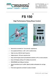
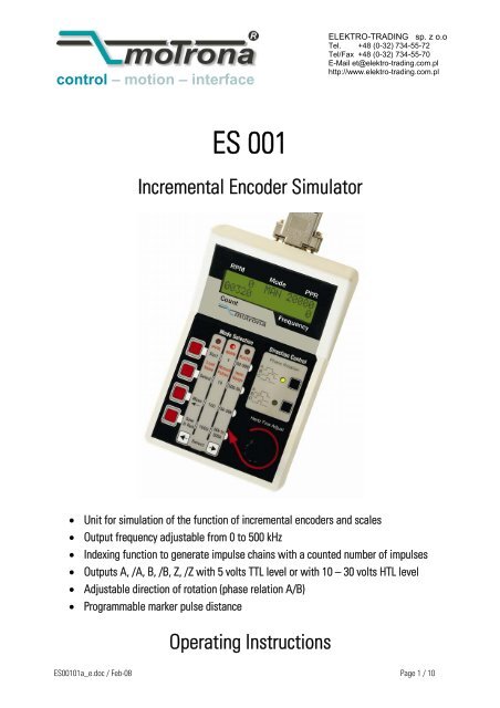
control – motion – interfaceELEKTRO-TRADING sp. z o.oTel. +48 (0-32) 734-55-72Tel/Fax +48 (0-32) 734-55-70E-Mail et@elektro-trading.com.plhttp://www.elektro-trading.com.pl<strong>ES</strong> <strong>001</strong>Incremental Encoder Simulator• Unit for simulation of the function of incremental encoders and scales• Output frequency adjustable from 0 to 500 kHz• Indexing function to generate impulse chains with a counted number of impulses• Outputs A, /A, B, /B, Z, /Z with 5 volts TTL level or with 10 – 30 volts HTL level• Adjustable direction of rotation (phase relation A/B)• Programmable marker pulse distanceOperating Instructions<strong>ES</strong><strong>001</strong>01a_e.doc / Feb-08 Page 1 / 10
Safety Instructions• This manual is an essential part of the unit and contains important hints aboutfunction, correct handling and commissioning. Non-observance can result indamage to the unit or the machine or even in injury to persons using theequipment!• The unit must only be installed, connected and activated by a qualified electrician• It is a must to observe all general and also all country-specific and applicationspecificsafety standards• When this unit is used with applications where failure or maloperation could causedamage to a machine or hazard to the operating staff, it is indispensable to meeteffective precautions in order to avoid such consequences• Regarding installation, wiring, environmental conditions, screening of cables andearthing, you must follow the general standards of industrial automation industry• - Errors and omissions excepted –Version:<strong>ES</strong><strong>001</strong>01a /kk/hk/Nov06Description:First edition<strong>ES</strong><strong>001</strong>01a_e.doc / Feb-08 Page 2 / 10
Table of Contents1. Introduction....................................................................................................42. Connections ...................................................................................................52.1 TTL or HTL Output Level ........................................................................................52.2 Connection to Other motrona Units ......................................................................63. Display Panel and Control Panel....................................................................73.1 Display Panel.........................................................................................................73.2 Control Panel .........................................................................................................83.3 Operating Modes PPR, MAN and RATE................................................................83.3.1 The PPR Mode.................................................................................................................83.3.2 The MAN Mode ..............................................................................................................93.3.3 The RATE Mode ..............................................................................................................93.3.4 Direction Control.............................................................................................................94. Specifications and Dimensions....................................................................10<strong>ES</strong><strong>001</strong>01a_e.doc / Feb-08 Page 3 / 10
1. IntroductionIncremental encoders and measuring systems can be found in nearby every application ofmachine building industry. With consideration of this, an adequate simulator can beadvantageously used for the following jobs:• Testing of machine components or control units, without need to have all mechanicaldetails ready and available• „Dry testing“ during commissioning, with the machine in standstill• Setup and inspection of electronic measuring systems, converters, counters etc.including test of cables and wiring• Localization of error sources with malfunction and trouble-shooting<strong>ES</strong><strong>001</strong> provides simulation of a wide speed range, from single step and slow motion up toencoder frequencies of 500 kHz. The unit is suitable to generate TTL and HTL level impulseswith forward or reverse rotation, including a programmable zero pulse. Clearly arranged displayand operator panels ensure simple and easy operation of the unit.With simulation of encoders providing an integral part of a closed control loop,the frequency generated by the <strong>ES</strong><strong>001</strong> simulator will not follow the controlsignals of the system, which may cause irregular machine functions.For a complete closed-loop encoder simulation, please consider our V/f-convertermodel UF251.<strong>ES</strong><strong>001</strong>01a_e.doc / Feb-08 Page 4 / 10
2. ConnectionsThe diagram below shows the wiring of the unit via the 9-position Sub-D-connector (maleconnector on unit site). Assembled connection cables with female connector on one side andwires with conductor sleeves on the other side are available on request.GND V+ A B Z1 2 3 4 56 7 8 9A B ZThe unit accepts a power supply from 5 to 30 volts, which must be applied to pins 1 and 2 ofthe connector. The maximum current consumption is about 100 mA. In general, the same powersource will be used which normally would also supply the encoder, but also any other remotepower source is acceptable.Pin assignmentFor technical reasons, the pin assignment of the <strong>ES</strong><strong>001</strong> encoder simulator divergesfrom the usual motrona standard pin assignmentsIndication of insufficient power supplyAll LEDs will be lit at the same time when the supply voltage falls below theacceptable minimum level. When you observe this, the unit is not ready to work.2.1 TTL or HTL Output LevelThe square wave output swing only depends on the power supply voltage. To produce TTLoutputs, the simulator must receive a 5 volts power input. To produce HTL signals, the inputvoltage must be accordingly higher.The output level will always be about 1.5 volts lower than the power supply voltage.<strong>ES</strong><strong>001</strong>01a_e.doc / Feb-08 Page 5 / 10
2.2 Connection to other motrona unitsDue to different pin assignments, the two ends of a cable with Sub-D-connectors are notinterconvertible. To avoid misconnection, we recommend to either code the two connectors, orto at least mark the cable ends clearly.Sub-D-9 connectors (female)<strong>ES</strong> <strong>001</strong> motrona unit (e.g. BY 125)GND V+A B ZBAAV+GND1 2 3 4 56 7 8 91 2 3 4 56 7 8 9A B ZZZB<strong>ES</strong><strong>001</strong>01a_e.doc / Feb-08 Page 6 / 10
3. Display Panel and Control Panel3.1 Display PanelThe display panel is grouped into the following 5 sections:Section Description Setting Range Display RangeRPMActual speed (rev./min)(= 60 * Frequency/ PPR)0 …15000(with overflow)Mode Actual operating mode PPR, MAN, RATEPPR Preset number of pulses per rev. 2 ... 99999Count Number of output pulses 0 ... 99999Frequency Actual output frequency 40 Hz ... 500 kHzDepending on the operation mode, the display sections may have different meanings asdescribed under 3.3.<strong>ES</strong><strong>001</strong>01a_e.doc / Feb-08 Page 7 / 10
3.2 Control PanelThe control panel is grouped into the sections Mode-Selection, Direction Control and Hertz FineAdjustSelectionkeysDirectionPresetFrequencyFine AdjustMode Selection (PPR, MAN, RATE)3.3 Operating Modes PPR, MAN and RATEThe desired operating mode can be selected by means of the two Mode Select Keys. The redLED at the top of each column shows the selected function (PPR, MAN or RATE). At the sametime, the function appears in the mode section of the LCD display.3.3.1 The PPR ModeThis mode provides preselection of the desired encoder ppr number (number of encoder pulsesper revolution). The setting range is from 2 to 99999. The following functions are assigned tothe red selection keys:Key Function DescriptionStart Reset Starts a new selection process by setting the PPR number to an initialvalue of 2Select Increment The actual digit is incremented by 1(loop 1, 2,.., 9, 0, 1, 2, .. etc.)Move Shift the digitto leftShifts the actual digit one space to the left and automatically shifts azero to the previous position to increment the next digitSave & Run Store Stores the actual ppr setting and sets the counter in the „Count“section to zero. The unit is ready to work.The selected PPR number (= pulses between two marker pulses) appears in the „PPR“ section.<strong>ES</strong><strong>001</strong>01a_e.doc / Feb-08 Page 8 / 10
3.3.2 The MAN ModeThis mode provides the facility to manually control the number of output signals sent. Theprogress of this entry is displayed on the “Count” display.Each operation of one of the red keys sends the number of output pulses indicated on themiddle column of the control panel (1, 10, 100 or 1000 pulses).The associated output frequency can beforehand be selected in the “Rate” mode.3.3.3 The RATE ModeThis mode provides continuous impulse generation with the adjusted output frequency. Thefour red keys allow preselection of the following frequency ranges:• 50-500:• 500- 5k:• 5k-50k:• 50k-500k:Range 50 Hz to 500 Hz,Range 500 Hz to 5 kHz,Range 5 kHz to 50 kHzRange 50 kHz to 500 kHzSpeeds between the ranges can be adjusted by rotating the “Hertz Fine Adjust” knob.The LCD display indicates the following details:RPM Mode PPREncoder frequency (rev./min) RATE Number of pulses perencoder revolutionActual count number (position)Output frequencywithin one encoder revolution.CountFrequency3.3.4 Direction ControlTwo keys in the Direction Control Field provide selection of forward or reverse direction.Pressing the upper key results in a signal with output A rising before B.Pressing the lower key results in a signal with output B rising before A.The selected direction is indicated by a green LED.If none of the green LEDs is lit, this indicates that no output signal will be generated<strong>ES</strong><strong>001</strong>01a_e.doc / Feb-08 Page 9 / 10
4. Specifications and DimensionsPower SupplyOutputsDisplayOutput frequency:Connection: 5 – 30 Vdc, max. 100 mA: 3 line driver output channels (push-pull)(A, /A, B, /B, Z, /Z): LCD display 2 lines x 16 characters5,5 mm x 3 mm (.217 x .118’’): single step and 40 Hz – 500 kHz (4 ranges): 9-position Sub-D-connector (male on the unit)Conformity and standards : EMC 89/336/EEC: EN 61000-6-2EN 61000-6-3LV73/23/EEC: EN 61010-195 (3.740)150 (5.906)3040 (1.575)<strong>ES</strong><strong>001</strong>01a_e.doc / Feb-08 Page 10 / 10