Manual - Hawk Measurement Systems!
Manual - Hawk Measurement Systems!
Manual - Hawk Measurement Systems!

Create successful ePaper yourself
Turn your PDF publications into a flip-book with our unique Google optimized e-Paper software.
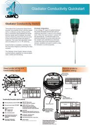
Acoustic Switch Series<strong>Manual</strong>Rev 1.5, Feb 2013Acoustic Switch Series<strong>Manual</strong>Rev 1.5, Feb 2013SYSTEM COMPONENTSWIRINGGLADIATOR AMPLIFIERAMPLIFIERSLAVE INMASTER OUTTEST INRELAY 1NCCOMNORELAY 2JUNCTION BOXREDBLACKBLUEWHITEREDBLACKBLUEWHITEREDBLACKBLUEWHITE+ –Relay 1 - Output RelayRelay 2 - FailSafe RelayAcoustic Switch Remote Transduerslabeled TD1 and TD2with UHMW flush mount sleeveFA4A 4” ANSI standard flangeHAWKAWRT-JB-01JUNCTION BOXConnect colour to colourREDBLACKBLUEWHITEREDBLACKBLUEWHITEREDBLACKBLUEWHITENCCOMNO16 17 18 19 20 21 22 23 24 25 26 27 28 29 30Is1 2 3 4 5 6 7 8 9 10 11 12 13 14 15REDBLACKBLUEWHITEBA– +NL14-20mA (N/A)SENSOR COMMS DC-In AC-In*AMPLIFIERTRANSDUCER 1 TRANSDUCER 245
Acoustic Switch Series<strong>Manual</strong>Rev 1.5, Feb 2013Acoustic Switch Series<strong>Manual</strong>Rev 1.5, Feb 2013SETUP PROCEDURESETTING MAXIMUM RANGE1. Mount the unit in its actual position(see mounting - pages 7-8)2. Check where the actual level or targetis relative to the sensors. Make sure thatthe material or target is not blocking thepath between the transducers.!4. Turn the power onThe display will turn on and the fail-safe relaywill switch. The display will scroll throughthe following messages: <strong>Hawk</strong>, AmpSerialNo, Type, Amp Soft Ver, Device ID,Unlock0CALQuickSetCALApp TypeCALCALCal MountingCALCALSwitch PointCALCALOn Delay AdjCALCALOffDelay AdjCALCALRelay ActionCALRUN10SensorSerial, SensorModel, Sens SoftVer,Sensor Addrs, Gladiator System Amp.The unit will then go into operational modedisplaying ‘Switch’ with a % value. This %value represents the changing amount ofsignal loss between the transducers.If you see an error code, see ‘troubleshooting’.5. Simple “1-minute” Setup - Follow theflow chartChoose Application TypeAlignment - For transducer alignment at long range (boom protection applications)Blocked Chutes - Configures the unit for blocked chute applications.Boom Protection - For anti collision / machinery detection.Switch - Allows selection of Sensitivity% for standard switch application.Note: If prompted to ‘re-calc app params’ this means the unit is already set to thatapp type - the unit is asking if you wish to re-configure the settings..Mounting CalibrationDo not proceed with this step unless the material or target position is well beneaththe line between the sender and receiver.Select ‘Yes’ to start the mounting calibration. ‘Wait’ will be displayed during thecalibration for up to 30 seconds. Unit is now able to cancel the influence of themounting. The % reading on the back lit display has been zeroed with the existingprocess conditions and the measurement history log has been cleared.Always CAL MOUNT after changing application type or moving the transducers.Select the Switch pointThe output relay will switch at the entered % value. The default value of 75% will besuitable for detecting most media. For detection of lighter / fine products select a lower% value and vice versa. For heavy materials almost any setting will work a higher %setting may be required. When the level or target falls below the sensors the relay willswitch back on.Select the Switch Time DelaySet the delay time for the relay switching on and off.Select the required relay actionThe Relay action can be defaulted to either ‘ON’ or ‘OFF’ and switch ‘ON’ or ‘OFF’in response to an instrument failure.Failsafe High - Relay is energised during normal operation and de-energisedduring blocked conditions or unit failure.Failsafe Low - Relay is de-energised during normal operation and energisedduring blocked conditions or unit failure.After a calibration the unit has a high &fluctuating switch%Check the echo distance diagnostic(while the unit is RUNNING, press downarrow until the top line reads E: x.xx.If this value (distance) is double the approximatespace between sensors or greater youwill need to adjust the ‘empty distance’ torestrict the maximum range.The setting is called ‘Empty Dist’ in the mainmenu labelled ‘Advanced’.Press CAL toedit, then the arrow to adjust this distanceto 125% of the space between the sensors(example, if there is approximately 4.00mbetween the sensors adjust this value to5.00m).11
Sensor Value0.0%Acoustic Switch Series<strong>Manual</strong>Rev 1.5, Feb 2013Acoustic Switch Series<strong>Manual</strong>Rev 1.5, Feb 2013FLOW CHARTSOFTWARE TREEOn first start up there isno security code protection.Percentage abovewhich the Relaywill be in State 2*.Percentage Sensor below Valuewhich the 0.0% Relaywill be in State 1*.Press} PressPressCALTo CalibrateMax/Min capturedSensor UnLock Value % sinceLast history 0 log reset,or last Cal MountingCALoperationNormal Running DisplayPress to view unitoperation diagnosticsDIAGNOSTICSto view informaiton about cur-While the unit is in RUN mode you can pressrent unit settings & operating characteristics.Current detected signal in %Sensor Value 0% full signal100% all signal blockedBlockedChuteSensor 1E1DistanceSigna1Selected ApplicationCurrently selected sensor for diagnosticsPress at the same time to switchbetween sensor 1 & 2 (in this menu only)Distance between sensors.May be displayed as double or triplevalue depending on chute conditions.Signal strength in voltage.2.5V maxDiagnostic0%Current sensor valueis always displayedon 2nd linePressTo QuickSetflow chartCALCurrent switchQuickSetdelay timeQuickSet Menucovers all parametersrequired for standardsetups.AdvancedPressAdvanced Menucovers less commonlyused or advancedparameters.CALTo Advancedflow chartRecov1Noise1Gain1Current recover gain% of sensor. Unit applies recovergain to maintain maximum possible signal strength.External noise interference % detected by sensor.Value may fluctuate during inactive process & emptychutes due to transducer ringing.Total Gain% useage of sensor.Calibrated starting gain + recover gain.PressRUNto return to normal operationSignalAverage signal strengthbeween both sensors.2.5V maxMinMinimum recorded sensorvalue % in logNormalUnit StatusNormal / CommRetryMaxMaximum recorded sensorvalue % in logSignal 1.86V0.0%Received Signal strengthTempDelayAmbient temperatureat sensorCurrent switch delaycount down. Value will beslightly lower due toresponse timeSW OffSW OnSensor value requiredfor switch off conditionSensor value requiredfor switch on conditionGain 10.2%0.0%Gain result of mounting12calibration13
Acoustic Switch Series<strong>Manual</strong>Rev 1.5, Feb 2013Acoustic Switch Series<strong>Manual</strong>Rev 1.5, Feb 2013QUICKSET FLOW CHARTQUICKSET PARAMETERSSoftware Rev 740QuickSetCALApp TypeCal MountingSwitch PointOn Delay AdjOffDelay AdjRelay1 ActionRUNCALCALCALCALCALCALSelect application typeAlignmentBlocked ChuteAnti CollisionSwitchCalibrates unit gain tocurrent conditionsYes / NoSwitch point conditionAuto = default 75%High value recommendedfor blocked chutes.Switch on time delaySwitch off time delayCALRecalculateApp type?Yes / NoIf you re-select the existing app typeyou will be prompted to confirm thatyou wish to adjust existing settingsCALSensitivityHigh value - Unit requires less signalblockage to switchLow value - Unit requires more signalblockage to switchFailsafe High - Relay1 is energised during normaloperation and de-energised during blocked conditions.Failsafe Low - Relay1 is de-energised during normaloperation and and energises during blocked conditions.Failsafe ConditionsPower / Comms problemsTransducer failureTransducers stop communicatingApp TypeAlignment - For Aligning the unit at longrange (boom protection applications). Unitis set to 1.2V signal (~48% sw value). Movethe unit face to get the sw value readinglow (0% indicates perfect alignment at currentgain setting). Calibrate & re-select thismode and repeat till you cannot improve thealignment. This mode is only for alignment,not for an active process.Blocked Chute - Configures the unit forblocked chute applicationsBoom Protection - Sets the unit to BoomProtection mode. This can also be used formachinery or object detectionSwitch - For standard switch applicationswhere blocked chute or boom protectionis not appropriate. A high value will makethe unit more sensitive to switching andresponding to lighter materials. A low valuewill make the unit more resilliant and ignoredust / build up.Cal MountingDo not proceed with this step unless thematerial or target position is well beneth theline between the transducers.Select ‘Yes’ to start the mounting calibration.‘Wait’ will be displayed during the calibrationduring the procedure and the StatusA & B lights will flash while the unit is pulsing.The unit then performs a final check.The Cal Mounting process configures thesystem to the optimum settings to achievea 2.4V signal (signal in volts viewable in thediagnostics).Switch PointAuto: The output relay will switch on at displayed% value (default 75%) Auto settingswill be suitable for detecting most media.Adjusting the switch on % will automaticallyadjust the switch off %. For blocked chuteapplications a higher % switch on value isrecommend such as 90%.<strong>Manual</strong>: To adjust both switch point valuessee ‘Switch Mode’ in the ‘Advanced’ menu.On & Off Delay AdjustmentSet the time to be used for both switch onand switch off delays (default: 1 second).Relay1 ActionRelay1 can be set to Low or High.When the Relay is in high mode it is alwaysswitched on (EN) and will switch off (DEN)when there is a blocked chute condition orunit failure. High is recommended.When in Low mode the Relay will beswitched off (DEN) during normal operationand will switch on (EN) when there is ablocked chute condition or unit failure.1415
Acoustic Switch Series<strong>Manual</strong>Rev 1.5, Feb 2013Acoustic Switch Series<strong>Manual</strong>Rev 1.5, Feb 2013ADVANCED MENU FLOW CHARTSoftware Rev 740ADVANCED MENU PARAMETERSAdvancedCALSwitch ModeRelay2ActionView LogReset LogComms TypeProbeAVGInitilize TXEmpty DistLoadDefaultsRUNCALCALCALCALCALCALCALCALCALAuto - Recommended setting<strong>Manual</strong> - <strong>Manual</strong>ly select switch on & off % valueFailsafe - Relay2 is always energised and will de-energisein the event of unit failure.Relay2 - Relay will operate same as Relay1 setting.For Maintnce Chk, GainOpt Clng, TimeOpt Clng see ‘Maintenance/Cleaner’Yes - Displays recently logged dataYes - Resets logged dataDevicenetProfibusHARTModbusCALComms typewill not work withoutcorrect module.Different Comms typesdisplay all or two of thefollowing.The number of pulses the unit uses to average thedisplay measurement.Yes / NoRun Transducer initialisation sequence.See page 19 for further information ontransducer initialisation.Distance (default 15.000m)Sets the max possible range for the application.Use if the system has calibrated to a longer echoBaud RateDevice IDYes / NoRestores the Transducer settings to factory default.You will be prompted to seset each Transducerindividually. Load defaults does not reset TX address.FieldBusAddsSwitch ModeSwitch mode alters the switch on/off display% condition for the relay. Auto is the recommended<strong>Hawk</strong> default with switch on at 75%<strong>Manual</strong> mode allows you to specify the on& off % condition.Relay2ActionThe second relay can be set for failsafe conditionsor as another switch. Usually failsafeis the preferred option. The relay will alwaysbe switched on but will switch off if there is afail condition with the system.Failsafe Conditions:Power / Comms problemsTransducer failureTransducers stop communicatingThe second relay2 action is relay2. Thisprograms the relay to mirror the action ofrelay1.See ‘Maintenace/Cleaner’ on next page forinformation about Maintnce Chk, GainOpt &TimeOpt CleaningView LogView log displays the highest & lowestlogged values for the display % and temperaturesince the last log reset.Reset LogClears the logged data.Comms TypeIf your unit has an additional comms module(Modbus is standard with switch only units)such as Devicenet, Profibus PA or HARTyou can select and configure the address /ID / line speed for the comms option.Back LightThe LCD back light can be switched on oroff. The display will be bright green whenswitched on.ProbeAVGThis setting is similar to a ‘damping’ setting.The unit display reading will be an averageof the ProbeAVG figure. The figure ismeasured in transducer pulses. The defaultsetting is 2. Increasing this setting will slowthe unit response time for switching andgive a more stable switch % value.Initilize TX (see page 20)If you need to re-initialize the transducer addressconnection sequence you can run thisprogram. You will have the option to cleareach transducer address. If the transducersare already correctly addressed withinthe amplifier the unit will cycle through anddisplay ‘found’ and then ‘too many transducers’.In this event press and hold RUN firmlyto return to the menus.V In ChkV in Chk ensures the minimum requiredvoltage for unit operation (9.5V) is beingsupplied to the unit. If switched off the LCDwill display ‘volt fail’ when voltage dropsbelow 9.5V. When switched on the unit willenter failsafe mode and display volt failwhen input voltage drops below 9.5V.Empty DistSee ‘setting maximum range’ on P11LoadDefaultsRestores factory default settings to amplifier,sensor 1 and sensor 2. You will beprompted to set each individually.1617
Acoustic Switch Series<strong>Manual</strong>Rev 1.5, Feb 2013Acoustic Switch Series<strong>Manual</strong>Rev 1.5, Feb 2013MAINTENANCE/CLEANERTROUBLESHOOTINGConceptThe Gladiator Amplifier has received afirmware update to utilise the Relay 2 asa trigger mechanism to notify the user oractivate a cleaning system based on timeor conditions within the application whichrequire cleaning.There are three software options usingtwo diffferent concepts. The first concept isbased on total Gain used and the second isbased on a Time interval.The options are located in the Advancedmenu as a sub menu for Relay2Action.The selectable software options are asfollows:[Maintnce Chk] - The unit will switch on therelay when total Gain is greater than theCleanGainHigh % - the relay will switch offwhen Gain falls below CleanGainLow %.[GainOpt Clng] - When total Gain exceedsthe CleanGainHigh point the unit activatesthe relay for 1/2 of the On Delay time andthen switches off. The unit will then countthe Clean Time interval time before repeatthe process until total Gain is below Clean-GainLow point.[TimeOpt Clng] - At every Clean Time intervalthe unit will switch on the relay for 1/2 ofthe On Delay time and then switch off.Setup Example - Time BasedIn ‘Quickset’ Set ‘On Delay’ to 4.0 seconds -this will provide a 2.0 second water blast.In ‘Advanced’ set ‘Relay2Action to ‘TimeOpt-Cln’ with a ‘Clean Timer’ of 30min.Every 30 minutes the sensors will besprayed for 2 seconds.Setup Example - Gain BasedIn ‘Quickset’ Set ‘On Delay’ to 4.0 seconds -this will provide a 2.0 second water blast.In ‘Advanced’ set ‘Relay2Action to ‘GainOpt-Cln’ with a ‘CleanGainHi’ of 80%, ‘Clean-GainLo’ of 70% and ‘Clean Timer’ to 5.0minThis will trigger the water spray for 2seconds when Gain goes above 80%. Thespray will repeat every 5 minutes until Gaingoes below 70%. You can view Gain whilethe unit is running by using the arrow key tolocate the diagnostic displayERROR CODESToo Many Transducers - This code can bedisplayed if both transducers are alreadycorrectly initialised when run the InitialiseTX program. Press and hold the RUNbutton to exit this code loop.Com Retry - Unit is attempting tocommunicate with a transducer.Failed - Unit has failed to communicate withboth transducers. Check amplifier & junctionbox wiring connections. Pull each wire toensure they are locked in correctly.Error No 01 - Amplifier cannotcommunicate with transducer 1.Error No 11 - Amplifier cannotcommunicate with transducer 2.Existing installation: For both error codes1 and 11 the first thing to check is theamplifier & junction box wiring connections,both <strong>Hawk</strong> and customer supplied ifapplicable. Pull each wire to ensure theyare locked in correctly. Check sensor fordamage.New installations: You may need tore-initialise the transducers. The reinitialisationsequence assigns eachan ID which the amplifier is looking tocommunicate with.The re-initialise program is in the ‘Advanced’Menu. While an error code is on the screenyou will need to push and firmly hold theCAL button to access the unlock screen.This may take 5-10 seconds.Error 02: Amplifier can talk to transducerbut transducer gives incorrect response.This can indicate a communicationdata corruption between Amplifier andTransducer. It can be a result of noise indata lines or one of data lines (blue or white)being open circuit.Error 03: A communications option inoutput adjustment has been selected (egProfibus, FF) but the module is not present,connected or responding.Error 04: Amplifier is programmed withincorrect software.Error 08: Incorrect transducer - ensureconnected transducer is Acoustic Switch(AS).POWER SUPPLYLCD / LEDs / Relays dimming or droppingout in non-blocked conditions.The GSASUS when powered by AC willoutput a DC voltage from the DC +/-terminals.You should read approx 16V stable from DC+/- while under AC power. If your AC poweris stable and the DC is outputting a lower orunstable value there is likely a problem withthe internal AC power supply. You can usea 24DC regulator and power the unit via DCterminals.High / Inconsistance switch % aftercalibrationSee ‘setting maximuim range’1819
Acoustic Switch Series<strong>Manual</strong>Rev 1.5, Feb 2013Acoustic Switch Series<strong>Manual</strong>Rev 1.5, Feb 2013TRANSDUCER RE-INITIALISATIONPART NUMBERINGError 01 - Error 11If the LCD is displaying ‘Error 01 or Error11 after installing a single transducer orfull system you may need to re-initialise atransducer. If your system is displaying Error01 or Error 11 after the system has beenworking correctly it is very likely there is adifferent problem. If Comm Err is displayedwhile navigating menus check your wiring,terminals, junction boxes and transducersfor damage or connection problems.Initilizing a TransducerIf you need to re-initialize the transduceraddress you can run this program. You willhave the option to clear each & initialisetransducer address.First - Disconnect Transducer 2Press and hold CAL to force the unit toopen the ‘unlock’ menu. Navigate to theInitilize TX menu as per belowUnlock 0CALAdvancedCALx3Initilize TXCAL *edit*Yes CALAfter selecting ‘Yes’, you will see one of thesemessages: T’ducer 1READYT’ducer1Initilize?Plz connectTransducer 1T’ducer 1ReadyDuring the boot sequence of the amplifierinformation about each transducer is cycledon the LCD. Each transducer will pulseonce during this phase confirming power ispresent.If both transducers pulse at the same timethey have been assigned the same TX ID.You will need to re-initialise one of them.T’ducer1 Initilize?Transducer 1 is detected and has not beeninitialised. Press CAL to edit, press UP until yousee ‘Yes’. Press CAL to select.Re-connect Transducer 2 and press RUN severaltimes to re-activate the unit.Plz connect Transducer 1Press RUN firmly until it moves to 2nd Transducer.Display should read ‘T’ducer 2 Ready’. PressCAL to edit, press UP twice to display ‘Clear?Yes’. Press CAL.The unit will not have returned to the advancedmenu. Press UP and re-enter TX initilize. Youshould now be prompted with T’ducer1 Initilze,refer to relevant steps.T’ducer 1 ReadyPress CAL to edit, press UP twice to display‘Clear? Yes’. Press CAL. The unit will cycle toT’ducer 2 displaying ‘Ready’.Re-connect Transducer 2 and press RUN severaltimes to re-activate the unit.T’ducer1Initiliz? NoREMOTE AMPLIFIERGSARemote Gladiator System AmplifierHousingS Standard polycarbonate electronics housingPower SupplyB 12-30VDCC 30-48VDC & 48-90VACU 12-30VDC & 90-260VACOutput OptionsS Switch. 1 level relay, 1 failsafe relay, with ModbusGSA S U SJUNCTION BOXAWRT-JB-01MOUNTING FLANGEFA4A-4<strong>Hawk</strong> multi purpose junction box for dual transducer applicationsIncludes 1m amplifier connection cable.<strong>Hawk</strong> Transducer body mounted 4” ANSI flangeEXTRA CABLE (length in metres)CA-TXCC-R-C15C30C50C1002021
Acoustic Switch Series<strong>Manual</strong>Rev 1.5, Feb 2013Acoustic Switch Series<strong>Manual</strong>Rev 1.5, Feb 2013PART NUMBERINGSPECIFICATIONSREMOTE TRANSDUCERAWRT Acoustic Wave Remote Transducer15 15kHz for chutes with heavy duty self cleaning requirementsTransducer Diaphragm / Sleeve MaterialT Teflon / UHMW (applications suitable for Teflon (no sensor face wear))Y Titanium face / UHMW (applications with possible sensor face wear eg crushers)Transducer Housing Material4 PolypropyleneThread Standards for End capX Not Available (FA4A-4 Standard Flange Mount)Mounting Thread SizesX Not Available (FA4A-4 Standard Flange Mount)Approval Standard (contact factory for hazardous location approval options)X Not RequiredA22 ATEX Dust (Grp II Cat 3 D T85C IP67)ConnectionC IP68 Sealed unit with cableCable Length15 15m cable30 30m cableAccessoriesX UHMW SleeveSoftware OptionsAS Gladiator Acoustic Wave SwitchAWRT 15 Y 4 X X XC 15 X ASOperating Voltage• 12-30VDC (residual ripple no greater than 100mV)• 90-260VACPower Consumption•
ContactsRev 1.4, Sept 2011<strong>Hawk</strong> <strong>Measurement</strong> <strong>Systems</strong> (Head Office)15-17 Maurice CourtNunawading VIC 3131AustraliaPhone: +61 3 9873 4750Fax: +61 3 9873 4538info@hawk.com.au<strong>Hawk</strong> <strong>Measurement</strong>7 River StreetMiddleton, MA 01949USAPhone: +1 888 HAWKLEVEL (1-888-429-5538)Phone: +1 978 304 3000Fax: +1 978 304 1462info@hawkmeasure.comFor more information and globalrepresentatives:www.hawkmeasure.comRepresented by:Part no. DOC-ACOUSTICSW-MAN